1
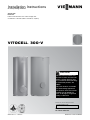
Installation Instructions
for use by heating contractor
Vitocell 300
EVI Series
Indirect-fired domestic hot water storage tank
53 USG and 120 USG (200 L and 450 L) capacity
VITOCELL 300-V
r
CAUTION
The heat transfer medium must
be water or other non-toxic fluid
having a toxicity rating or class
of 1, as listed in clinical toxicology
of commercial products, 5th
edition.
This tank version is not suitable
for steam heating applications.
The pressure of the heat transfer
medium must be limited to a
max. of 30 psig by an approved
safety or relief valve.
Product may not be exactly as shown
IMPORTANT
Read and save these instructions
for future reference.
5608 490 v1.2 09/2012
Please file in Service Binder
Introduction
Vitocell 300-V Installation Instructions
Safety, Installation and Warranty Requirements
Please ensure that these instructions are read and understood before commencing installation. Failure to comply with
the instructions listed below and details printed in this manual can cause product/property damage, severe personal
injury, and/or loss of life. Ensure all requirements below are understood and fulfilled (including detailed information
found in manual subsections).
g
Licensed professional heating contractor
The installation, adjustment, service and maintenance
of this equipment must be performed by a licensed
professional heating contractor.
g
Advice to owner
Once the installation work is complete, the heating
contractor must familiarize the system operator/
ultimate owner with all equipment, as well as safety
precautions/requirements, shutdown procedure, and
the need for professional service annually before the
heating season begins.
g
Warranty
Information contained in this and
related product documentation must
be read and followed. Failure to do
so renders the warranty null and void.
uPlease see section entitled
“Important Regulatory and Installation
Requirements”.
g
Product documentation
Read all applicable documentation before commencing
installation. Store documentation near product in a
readily accessible location for reference in the future
by service personnel.
uFor a listing of applicable literature,
please see section entitled “Important
Regulatory and Installation Requirements”.
In solar applications
CAUTION
The heat transfer medium must be either potable water
or contain only substances which are recognized as safe
by the U.S. Food and Drug Administration.
2
5608 490 v1.2
The Pressure of the heat transfer medium must be
maintained less than the normal minimum operating
pressure of the potable water system
Vitocell 300-V Installation Instructions
Contents
Page
Introduction
Safety, Installation and Warranty Requirements..............2
Licensed professional heating contractor.....................2
Product documentation.............................................2
Advice to owner......................................................2
Warranty................................................................2
Safety
Important Regulatory and Installation Requirements........4
Codes.....................................................................4
Mechanical room.....................................................4
Working on the equipment........................................4
Technical literature..................................................4
General Information
About These Instructions.............................................5
Product Information.....................................................5
53 USG to 120 USG (200 L to 450 L) capacity..........5
Set-up and Connections
Tank Connections.......................................................6
Tank Set-up...............................................................7
53 and 79 USG (200 and 300 Liter) Tank Installation....8
Thermal insulation and thermometer installation..........8
53 to 120 USG (200 to 450 Liter) Tank Installation.......9
Temperature sensor installation (when using
a Vitotronic 200 / 300 or Vitodens 200).....................9
Temperature sensor installation for solar operation...10
120 USG (450 Liter) Installation.................................11
Levelling and bottom thermal insulation....................11
Fitting the thermal insulating jacket..........................12
Fitting the thermometer and thermometer sensor
(if supplied) and covers...........................................13
Aquastat installation (when using a Vitotronic 100)............14
Grounding connection.............................................14
Boiler Water Connections (heat exchanger connection)...15
Recommended piping for solar application
with an additional tank.........................................15
Domestic Water Connections......................................16
Recirculation Connections..........................................18
Saving Energy........................................................18
Multiple Tank Set-up [only for 79 and 120 USG
(300 and 450 L) capacities].......................................19
Additional Information
Pressure Drop Information..........................................21
5608 490 v1.2
Installation of Inspection Opening...............................22
Post Installation......................................................22
Service binder........................................................22
Start-up information...............................................22
3
Safety
Vitocell 300-V Installation Instructions
Important Regulatory and Installation Requirements
Codes
The installation of indirect-fired hot water storage tanks
in boilers and solar system application might be governed
by individual local rules and regulations for this type of
product, which must be observed. Always use latest
editions of codes.
In the Commonwealth of Massachusetts, all plumbing
work must be done by a licensed plumber or gas-fitter
and for gas installations, all gas piping must be done by
a licensed gas-fitter.
Mechanical room
Ensure the mechanical room complies with the
requirements of the system design guideline and/or
Technical Data Manual (available from your Viessmann
sales representative).
The tank must be installed in a mechanical room which is
never subject to freezing temperatures.
Ensure water in tank is drained if not in use and danger of
freezing exists in the mechanical room.
uPlease carefully read this manual prior to attempting
installation. Any warranty is null and void if these
instructions are not followed.
This product must be installed observing not only the
information and instruction provided in the pertinent
product literature (see list on following page), but also
all local, provincial/state plumbing and building codes,
as they apply to this product and all periphery
equipment.
For information regarding other Viessmann System
Technology componentry, please reference
documentation of the respective product (available from
your Viessmann sales representative).
We offer frequent installation and service seminars to
familiarize our partners with out products. Please inquire.
WARNING
If the heating system itself is to be filled with Glycol or
any other antifreeze, the system fill must be of non-toxic
or food grade antifreeze. In any circumstance, a non-toxic
fluid must be used. Ensure a copy of the Material Safety
Data Sheet (MSDS) is supplied to the operator/ultimate
owner of the system. The use of Viessmann supplied
“Tyfocor-HTL” solar fill is recommended for the solar
heating circuit.
Working on the equipment
The installation, adjustment, service, and maintenance
of this equipment must be done by a licensed professional
heating contractor who is qualified and experienced in
the installation, service, and maintenance of hot water
heating systems. There are no user serviceable parts on
this equipment.
uThe completeness and functionality of field supplied
electrical controls and components must be verified
by the heating contractor. These include low-water
cut-offs, flow switches (if used), staging controls,
pumps, motorized valves, air vents, thermostats,
temperature controls, etc.
Ensure main power supply to equipment, the heating
system, and all external controls has been deactivated.
Close main oil or gas supply valve. Take precautions to
avoid accidental activation of power during service work.
4
uLeave all literature at the installation site and advise the
system operator/ultimate owner where the literature
can be found. Contact Viessmann for additional copies.
5608 490 v1.2
Technical literature
Literature applicable to all aspects of the Vitocell:
- Technical Data Manual
- Installation Instructions
- Start-up/Service Instructions
- Operating Instructions and User’s Information Manual
Vitocell 300-V Installation Instructions
General Information
About These Instructions
Take note of all symbols and notations intended to draw attention to potential hazards or important product information.
These include “WARNING”, “CAUTION”, and “IMPORTANT”. See below.
WARNING
Indicates an imminently hazardous situation which, if
not avoided, could result in substantial product/property
damage, serious injury or loss of life.
CAUTION
Indicates an imminently hazardous situation which, if not
avoided, may result in minor injury or product/property
damage.
IMPORTANT
u
uWarnings draw your attention to the presence of
potential hazards or important product information.
uCautions draw your attention to the presence of
potential hazards or important product information.
uHelpful hints for installation, operation or maintenance
which pertain to the product.
uThis symbol indicates that additional, pertinent
information is to be found.
uThis symbol indicates that other instructions must be
referenced.
Product Information
53 USG to 120 USG (200 L to 450 L) capacity
5608 490 v1.2
Indirect-fired domestic hot water storage tank with
one heat exchanger coil for use with hot water heating
boilers, residential/commercial heating plants, and lowtemperature heating systems.
These tank versions are not suitable for steam heating
applications.
5
Set-up and Connections
Vitocell 300-V Installation Instructions
Tank Connections
Legend
DHW
Domestic hot water supply
RT
Recirculation tapping
TS/AQ DHW temperature sensor or aquastat of boiler
control (upper indirect coil)
BWS
Boiler water supply *1
BWR
Boiler water return *1
DCW
Domestic cold water supply
*1
Part
Vitocell 300-V
Size
53/79 USG
(200/300 L)
120 USG
(450 L)
B Brass cap
1 in.
1
--
A Brass adaptor
1 in.
3
--
C Brass tee
1 in.
1
--
1
--
2
--
D Reducer hex bushing 1 in. x c in.
F Brass adaptor
1 in. + gasket
B Brass cap
1a in.
--
1
A Brass adaptor
1a in.
--
5
C Brass tee
1a in.
--
1
--
1
1
1
D Reducer hex bushing 1a in. x c in.
E Temperature and
pressure relief valve
6
c in.
5608 490 v1.2
Supplied adaptor sizes
The upper indirect coil is provided for connection
to a boiler or a heat pump.
Set-up and Connections
Vitocell 300-V Installation Instructions
Tank Set-up
- For narrow passageways, remove upper and lower
portion of crating and carry DHW tank to its installation
location by means of crating boards mounted on the tank.
- Position tank carefully and remove wood crating.
- Leave adequate clearance to the wall or other objects
enabling easy access to the aquastat (where applicable).
- Install tank(s) on flooring or foundation capable of
supporting the weight of the tank(s) filled with water.
- The tank does not require a special foundation and can
be placed directly on the floor. If, for cleanliness
purposes, the tank is to be kept off the floor, a
foundation can be used for each tank or group of tanks.
CAUTION
Install the DHW tank in a frost-protected and draft-free
room. Otherwise it must be drained when not in use, in
order to reduce the risk of damages caused by freezing.
IMPORTANT
Provide sufficient clearances towards the wall to allow
the aquastat to be operated (if installed).
Recommended service clearances
Rear
in. (mm)
18 (460)
in. (mm)
12 (300)
Top
in. (mm)
12 (300)
Front
in. (mm)
24 (600)
Sides
May be reduced if rear pipe connections can
be reached with less clearance
Minimum clearances to combustibles
All sides
in. (mm)
Floor
0 (0)
combustible
1. Apply Loctite 55 as per supplied instructions to each
tank nipple. Use Loctite 55 provided in the installation
fittings package.
5608 490 v1.2
2. Connect female ends of brass adaptors to the tank
nipples.
7
Set-up and Connections
Vitocell 300-V Installation Instructions
53 and 79 USG (200 and 300 Liter) Tank Installation
Thermal insulation and thermometer installation
All required components are included in the insulation
jacket carton.
1. Level the DHW tank with its leveling bolts.
IMPORTANT
Do not extend the leveling bolts beyond an overall
length of 1½ in. (35 mm).
2. Remove top cover and the thermal insulation blanket.
3. Insert the thermometer sensor into the tank cap hole
as far as it will go.
4. Secure the sensor with a spring clip. Install the top
cover and the thermal insulation blanket.
IMPORTANT
Never wrap insulating tape around the sensor.
8
5608 490 v1.2
Note: the 53 and 79 USG (200 and 300 L) tank comes
with the insulation jacket installed.
Set-up and Connections
Vitocell 300-V Installation Instructions
53 to 120 USG (200 to 450 Liter) Tank Installation
Temperature sensor installation (when using a Vitotronic
200 / 300 or Vitodens 200)
IMPORTANT
Never wrap insulating tape around the sensor.
1. Carefully pull sensor mounting hardware out from tank
sensor well.
2. Mount sensor on the outside of the sensor spring-clip
(not in the center groove) so that it is flush with the
front of the sensor spring-clip.
3. Push sensor cabling into groove of mounting hardware.
4. Carefully tighten plastic screw to secure sensor cabling
in place.
IMPORTANT
Due to the length of the stainless steel well 15 in. (380 mm),
care must be taken to ensure that the sensing bulb of the
limit is inserted and pushed to the end of the stainless
steel well.
5. Install sensor well and reducing coupling (included in
Connection Fitting Package). Use approved pipe sealant.
6. Mount insulation on sensor well.
7. Insert DHW tank temperature sensor (supplied with
Vitotronic 200 or 300) fully and completely into
sensor well.
WARNING
To ensure maximum operational reliability, use the sensor
well supplied for the control device sensor or probe.
Use a different stainless steel (1.4571 or 1.4435) sensor
well, if the sensor or probe does not fit into the supplied
sensor well.
8. Carefully tighten screw on sensor well to secure
sensor in place.
5608 490 v1.2
Note: When using a Vitotronic 100 boiler control, refer to
page 13 for aquastat installation.
9
Set-up and Connections
Vitocell 300-V Installation Instructions
53 to 120 USG (200 to 450 Liter) Tank Installation
(continued)
Temperature sensor installation for solar operation
using 53 and 79 USG (200 and 300 L) tanks
The temperature sensor for solar operation is included in
the solar control unit package.
The brass elbow with sensor well is available as an
option and must be used when solar connection is
required.
1. For solar operation, install the sensor well into the
brass elbow and connect the assembly to the solar
return line.
2. Insert the temperature sensor until it bottoms out
inside the sensor well.
IMPORTANT
Never wrap insulating tape around the sensor. Do not
install solar tank sensor anywhere other than the brass
elbow with sensor well.
Temperature sensor installation for solar operation
using 120 USG (450 L) tank
The temperature sensor for solar operation is included in
the solar control unit package.
The brass elbow with sensor well is available as an option
and must be used when solar connection is required.
1. For solar operation, install the sensor well/brass elbow
and connect the assembly to the solar return line.
2. Insert the temperature sensor until it bottoms out
inside the sensor well.
IMPORTANT
Never wrap insulating tape around the sensor. Do not
install solar tank sensor anywhere other than the brass
elbow with sensor well.
10
5608 490 v1.2
3. Tighten screws to secure sensor (do not over tighten).
Set-up and Connections
Vitocell 300-V Installation Instructions
120 USG (450 Liter) Tank Installation
(continued)
Levelling and bottom thermal insulation
All necessary parts for enclosure assembly are packaged
in a separate carton.
1. Fit the thermal insulation blanket below the tank prior
to the installation of the tank itself.
2. Position and level the DHW tank with its leveling bolts.
CAUTION
5608 490 v1.2
The thermal insulation must not come in contact with
open flames. Exercise extreme caution when welding
and soldering.
IMPORTANT
Do not extend the leveling bolts beyond an overall
length of 1½ in. (35 mm).
11
Set-up and Connections
120 USG (450 Liter) Tank Installation
Vitocell 300-V Installation Instructions
(continued)
Fitting the thermal insulation jacket
Note: - insulation remnants must not enter the tank
through the tank connections.
- 2 people are recommended to complete this work.
1. Fit both halves of the insulation jacket close to the tank.
Orient the jacket so the profile cutouts match the tank
fittings.
2. At the rear of the tank, install all 6 clip closures evenly
to both halves of the insulation jacket.
3. At the front of the tank, install all 6 clip closures
evenly to both halves of the insulation jacket.
4. At the rear of the tank, tighten all 6 clip closures
until both halves of the insulation jacket meet.
12
5608 490 v1.2
5. At the front of the tank, tighten all 6 clip closures
until both halves of the insulation jacket meet.
Set-up and Connections
Vitocell 300-V Installation Instructions
120 USG (450 Liter) Tank Installation
(continued)
Fitting the thermometer and thermometer sensor
(if supplied) and covers
1. Smooth out the insulation jacket by tapping the jacket
evenly against the tank.
5608 490 v1.2
2. Route thermometer capillary tube through the
front cover hole and insulation jacket, then snap the
thermometer in place.
6. Install the back seam cover.
7. Insert the thermometer sensor into the tank cap hole
as far as it will go.
8. Secure the sensor with a spring clip.
3. Insert the thermometer probe under the clip.
9. Install the top insulation and press down the edges
as shown.
4. Install the front cleanout cover and the front lower
seam cover.
10.Install the top lid and press the logo A into the lid.
5. Install the upper front seam cover.
Note: Seal the hole in the seam cover below the
thermometer with a cover.
13
Set-up and Connections
Vitocell 300-V Installation Instructions
Aquastat Installation (when using a Vitotronic 100)
Where a Vitotronic 100 and a Viessmann Power/Pump
Control Module (accessory) are utilized to control DHW
production, follow these aquastat mounting instructions:
Probe style aquastat
1. Insert the extended capillary of the aquastat (supplied
with Viessmann Power/Pump Control Module, not
illustrated) fully and completely into sensor well. Mount
aquastat inconspicuously on tank paneling.
Follow instructions below with regard to sensor and
spring clip installation.
... if aquastat is to be mounted remote from the tank well,
2. Align sensor bulb with spring clip.
3. Slide assembly into well.
4. The retention spring clip must press the bulb properly
to ensure surface contact with the well.
... if aquastat is to be mounted directly on the tank well,
5. Mount aquastat with holding clip supplied directly onto
well. Bend capillary tube into groove opening to allow
for mounting of aquastat.
WARNING
To ensure optimum, safe operation, the supplied
stainless steel well must be installed. The well diameter
is large enough to accommodate a wide variety of
sensing bulbs.
Always use spring clip to ensure proper contact of
capillary bulb against the stainless steel well for proper
sensing/heat transfer!
Grounding connection
Connect the grounding in accordance with the requirements
stipulated by your local electricity supply company and
current local regulations.
WARNING
The operating aquastat and any secondary high limit
aquastat of the tank must be set such that the DHW
temperature inside the tank never exceeds 203° F (95° C).
WARNING
IMPORTANT
Use a Loctite 55 string and pipe dope on all threaded
nipples on tank.
14
Feel water before bathing or showering.
Temperature limiting valves are available and must
be used where domestic hot water storage tank
temperatures exceed 140° F (60° C).
5608 490 v1.2
Domestic hot water temperatures over 125° F (52° C)
can cause severe burns instantly or death from scalds.
Children, disabled and elderly are at highest risk of
being scalded.
Set-up and Connections
Vitocell 300-V Installation Instructions
Boiler Water Connections
(heat exchanger connection)
Recommended piping for solar application with an additional tank
Legend
A
B
C
D
E
F
G
Solar collector
High limit safety cut-out
Filling valve
Solar-Divicon
Vitocell-V 300
Individual DHW tank heating system
Anti-scald temp[ering valve
WARNING
Due to the potentially high DHW temperatures generated
by the solar heating system, the domestic hot water
temperature must be limited to a maximum of 140º F (60º C)
by installing a anti-scald tempering valve. The tempering
valve does not completely eliminate the risk of scalding at
the tap. The installation of a mixing tap is recommended.
1. For boiler water supply temperatures over 203° F (95° C):
Remove plastic supply and return grommets
(grommets are left-threaded).
2. Pipe supply line with an incline and install an air vent
valve at the highest point.
3. For boiler water supply temperatures over 230° F
(110° C):
Install a type-tested high limit safety cut-out, if no other
has previously been installed in this system. For this
purpose, install a dual thermostat (high limit thermostat
and high limit safety cut-out).
4. Close off test nipples which are not used for the
installation of a probe or sensor.
IMPORTANT
5608 490 v1.2
Use a Loctite 55 string and pipe dope on all threaded
nipples on tank.
15
Set-up and Connections
Vitocell 300-V Installation Instructions
Domestic Water Connections
Note: - Connect all pipe work with detachable fittings.
Seal connections that are not required with red brass
caps.
Equip the DHW circulation pipe with circulation
pump, check valve and time switch. Gravity
operation is only feasible to a limited degree.
Always install DHW group of tanks with
connected DHW circulation.
1. Pipe together boiler and tank as illustrated. Connections
must be accessible for service (use factory supplied
adaptors).
2. Insulate domestic hot water supply piping.
IMPORTANT
This is a simplified conceptual drawing only! Piping and
necessary componentry must be field verified. Proper
installation and functionality in the field are the responsibility
of the heating contractor.
Legend
A
Spring-loaded flow check valve
B
Discharge pipe
C
Anti-scald tempering valve (field supplied)
SV
Shut-off valve
FV
Flow check valve
PR
Pressure reducing valve
D
Drain
DCW Cold water supply lines
PGC Pressure gage connection
E
Precharged expansion tank (required where backflow
preventer is installed; check local plumbing codes
and requirements)
BP1 Backflow preventer
BP2 Backflow preventer
T&P Temperature and pressure relief valve
DW Water filter
DHW Domestic hot water supply
RP
Recirculation pipe
RPU Recirculation pump
IMPORTANT
16
5608 490 v1.2
Use a Loctite 55 string and pipe dope on all threaded
nipples on tank.
Set-up and Connections
Vitocell 300-V Installation Instructions
Domestic Water Connections
(continued)
Always ensure the use of type approved devices.
Safety devices include the following components:
- Isolation valves
- Drain valve
- Pressure reducing valve
where required by local jurisdiction
- Drinking water filter
where required by local jurisdiction
- Backflow preventer
Where backflow preventers are required, a domestic
water expansion tank installation is required in the
cold water inlet piping before the cold water enters
the tank. The backflow device must be installed
according to the manufacturer’s installation
instructions. Observe local codes and regulations.
- Tempering valve
A tempering valve must be field installed where
storage tank (domestic hot water temperature)
exceeds local restricted temperatures or 140° F
(60° C). Check code requirements.
IMPORTANT
In situations where a booster pump is used to maintain
DHW pressure, Viessmann strongly recommends the
installation of an oversized large expansion tank to
ensure longer, less frequent pump cycles with less
severe pressure gradients. If possible, use flexible piping
before and after booster pump to isolate system piping
from vibration and shocks.
- Temperature and pressure relief valve
A temperature and pressure relief valve (T&P valve)
is supplied with the tank. The heating contractor must
install the valve on each tank in a method meeting
code requirements.
If local codes require a different relief valve, consult
Viessmann Manufacturing for a substitute valve.
The tank is approved for 150 psig. Maximum operating
pressure is 150 psig.
The T&P valve supplied with the tank is tested under
ANSI Z21.22 Code for Relief Valves and Automatic
Gas Shut-off Devices for Hot Water Supply Systems.
5608 490 v1.2
Watts Model
40XL-8
100 psig
(Canada) where
CRN is required
150 psig
ASME pressure
steam rating
998 MBH
1438 MBH
CSA
temperature
steam rating
205 MBH
205 MBH
Relief
temperature
210° F (99° C)
210° F (99° C)
Inlet thread
c” male
c” male
c” female
c” female
Outlet thread
The valve supplied with the tank is manufactured by Watts
Industries (Model 40XL-8) set to 100 psig for Canadian
installations and set to 150 psig for US installations
(where applicable). The valve is ASME pressure steam
rated for 998 MBH and CSA temperature steam rated for
200 MBH. It is tested under ANSI Z21.22 code for Relief
Valves and Automatic Gas Shut-off Devices for Hot Water
Supply Systems. The relief temperature is set at 210° F
(99° C). The valve has a male threaded inlet and female
threaded outlet, both ¾ in. sizes.
Proper installation of the T&P valve shall include all of the
following:
- The T&P valve shall be installed in the pipe connection
point marked TPV in the tank instruction manual.
- The discharge line from the T&P valve shall be ¾ in.
(1.9 cm) 7 and run to a safe place of discharge
approximately 1 ft. (30 cm) above the floor, close to
a floor drain.
- The discharge line must be as short as possible and
pitch downward from the T&P valve and terminate plain.
WARNING
The discharge line for the T&P valve must be oriented to
prevent scalding of attendants.
- Do not route discharge line to the outdoors.
- Do not install any type of valve or an obstruction
of any kind between the tank and the T&P valve, or
between the T&P valve and the discharge line outlet.
WARNING
The valve test lever must be operated at least once per
year by the owner to ensure that waterways are clear.
A licensed professional heating contractor shall reinspect
the T&P valve at least once every three years. Failure
to inspect can result in unsafe temperature or pressure
build-up, which can result in death, serious injury or
substantial product/property damage.
17
Set-up and Connections
Vitocell 300-V Installation Instructions
Recirculation Connections
Pipe domestic hot water supply piping with tank as
illustrated. Connections must be accessible for
service (use factory supplied adaptors).
Install recirculation pump, flow check valve and
recirculation timer (for shut-down during off-hours
where feasible) on the recirculation piping side.
Gravity circulation of the recirculation system is
restricted due to the upward-curved domestic hot
water discharge piping inside the tank.
Connect tanks to existing recirculation piping. Cap off
unused recirculation connections of individual tanks.
Saving Energy
A timer on the recirculation pump reduces the heat
loss significantly in commercial applications during
times when no or reduced demand for domestic hot
water occurs.
Connection of a recirculation system in a multiple tank installation for systems utilizing boilers or remote heating
plants without low temperature boiler return water
H
Legend
A Drawpoints
B Recirculation piping
C Circulation pump
D Spring-loaded flow check valve
E
F
G
H
Domestic cold water supply
Domestic hot water supply
Secondary high limit aquastat location
Air vent
Connection of a recirculation system in a multiple tank installation for remote heating plants with low temperature
boiler return water limit and/or for multiple recirculation lines
18
Legend
A Drawpoints
B Recirculation piping
C Circulation pump
D Spring-loaded flow check valve
E
F
G
H
Domestic cold water supply
Domestic hot water supply
Secondary high limit aquastat location
Air vent
5608 490 v1.2
H
Set-up and Connections
Vitocell 300-V Installation Instructions
Multiple Tank Set-up
[only for 79 and 120 USG (300 and 450 L) capacities]
Two tanks, each with 79 USG (300 L) content, or up to
four tanks, each with 120 USG (450 L) content, may be
installed side-by-side.
1. Install aquastat in the boiler water supply of the last
tank receiving the boiler water in a group of tanks (see
illustration).
The tanks are controlled via one DHW tank aquastat.
Individual control of tanks within the group of tanks is
therefore not possible.
2. Install domestic cold and hot water header lines (see
illustration).
3. Install boiler water supply and return header lines (see
illustration).
If control of individual tanks within a group of tanks is
necessary, two alternatives exist. Either a 4-tank group
can be separated into smaller groups, i.e. two batteries
each consisting of two tanks (one DHW tank aquastat
controls each group), or all tanks should be installed
individually, i.e. individual tank set-up (one DHW tank
aquastat controls each tank).
4. Make final cold and hot water connections.
IMPORTANT
Both the boiler supply/return header and the domestic
hot/cold water header must be installed in a reverse
return method. This ensures uniform heating of all tanks
in the group. Header sizes for batteries up to four 79 to
120 USG (300 to 450 L) tanks are listed below.
5. Insulate header piping lines.
CAUTION
In commercial installations, we recommend the installation
of an additional high limit aquastat in the main discharge
pipe of domestic hot water from a group of tanks into
the system, and to wire this additional high limit aquastat
in series with the operating aquastat.
Legend
A Domestic hot water supply and T&P valve connection
B Boiler water supply
C Operating aquastat
D Boiler water return
E Domestic cold water
F Drain
G Air vent
Storage capacity / Tank
USG (L)
Number of tanks
Layout
79 (300)
120 (450)
2
2
3
4
33
33
333
3333
5608 490 v1.2
Connections (individual tank)
Heating water supply/return (common header size)
7
2
2
2
Domestic cold/hot water (common header size)
7
1a
1b
2b
2
Recirculation tapping
7
1a
1
1a
1a
1a
19
Set-up and Connections
Multiple Tank Set-up
Vitocell 300-V Installation Instructions
[only for 79 and 120 USG (300 and 450 L) capacities] (continued)
All piping reverse return or use balancing valves.
1. Pipe together boiler and tanks as illustrated.
Connections must be accessible for service (use factory
supplied adaptors).
2. For boiler water supply temperatures over 203° F (95° C):
Remove plastic supply and return grommets (grommets
are left-threaded).
3. Pipe supply line with an incline and install an automatic
air vent at the highest point.
4. Install boiler sensor in sensor well (see page 9).
5. Insulate piping.
IMPORTANT
Recommended piping of multiple tanks
Legend
A Group of DHW tanks
B Sensor/Operating aquastat well
D Boiler water return
E Boiler water supply
F Domestic cold water supply
G Domestic hot water
H Drain
K Air vent
L Secondary high limit aquastat location
The circulation pump is activated by the operating aquastat
or by the control system installed. The operating aquastat
should be mounted on the tank which receives the boiler
water supply last.
Viessmann recommends the installation of an additional
high limit aquastat in the main discharge pipe of the DHW
system. This aquastat should be wired in series with the
operating aquastat and should be set approximately 9° F
(5° C) higher than the operating aquastat.
IMPORTANT
20
5608 490 v1.2
Use Loctite 55 pipe sealing cord and pipe dope on all
threaded stainless steel nipples on tank.
Additional Information
Vitocell 300-V Installation Instructions
Pressure Drop Information
Pressure drop on heating water side
(primary circuit)
Pressure drop
Pressure drop
Pressure drop on domestic hot water side
(secondary circuit)
Flow rate
Flow rate
5608 490 v1.2
A 79 USG (300 L) and 120 USG (450 L) storage capacities
B 53 USG (200 L) storage capacity
21
Additional Information
Vitocell 300-V Installation Instructions
Inspection Opening
Inspection opening and cover for 53 and 79 USG
(200 and 300 L) tanks.
Installation of inspection opening cover for 120 USG
(450 L) tank.
Post Installation
Service binder
1. File all Parts Lists, Operating and Service Instructions
in the Service Binder.
Start-up information
DHW Tank Start-up/Service Instructions
2. Install a protective hanging case near the boiler and
store the Service Binder in this location.
22
5608 490 v1.2
For a listing of applicable Viessmann literature, please
see Important Regulatory and Installation Requirements
on page 4.
5608 490 v1.2
Vitocell 300-V Installation Instructions
23
Vitocell 300-V Installation Instructions
5608 490 v1.2
Technical information subject to change without notice.
Printed on environmentally friendly
(recycled and recyclable) paper.