1
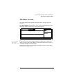
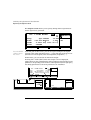
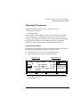
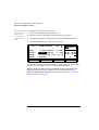
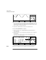
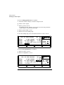
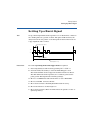
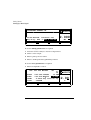
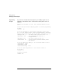
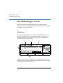
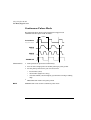
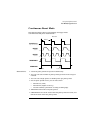
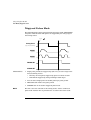
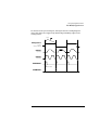
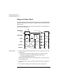
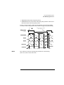
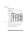
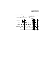
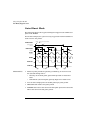
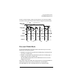
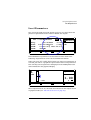
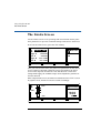
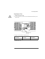
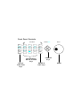
Using the Agilent 81101A The Mode/Trigger Screen Furthermore, you can specify the pulse and trigger sources. The following table provides a list of possible parameter combinations. The rows refer to the numbers in the figure. ➀ Trigger Mode Continuous ➁ Pulse Mode Pulses ➂ Pulse Type Single/Double ➃ Length ➄ Period Source ➅ Arming Source Triggered Burst Burst Single/Double 265536 Pulses Ext. Width Burst Single/Double 265536 internal Osc. internal PLL CLK-IN 265536 internal Osc. internal Osc. internal PLL internal PLL CLK-IN CLK-IN MAN key Ext. Input MAN key Ext. Input PLL MAN key Ext. Input MAN key Ext. Input marks each pulse period generated Trigger Out Strobe Out Pulses Gated not used ↑on 1st ↓on last not used ↑on1st ↓on last not used ↑on 1st ↓on last not used The pulse period source can be selected from internal oscillator, internal PLL, and external CLK-IN: If you have to trigger after an external event, use the startable oscillator (internal Osc.), which starts on the external signal with a fixed latency. If you do not have to trigger but need a high accuracy frequency, then use the internal PLL clock generation circuitry. For even more accuracy, you can use the external CLK-IN. In triggered/gated mode the internal PLL can be used as an arming source. However, the internal PLL cannot be used as pulse and arming source at the same time. The following sections explain the individual mode combinations in more detail. For each combination of trigger mode and pulse mode, typical timing diagrams are provided, showing single and double pulses. 45