1
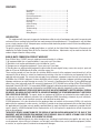
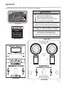
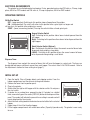
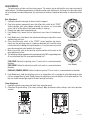
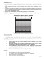
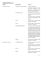
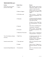
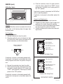
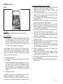
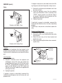
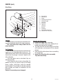
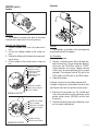
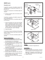
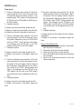
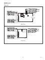
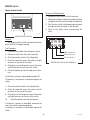
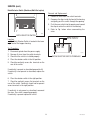
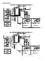
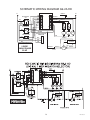
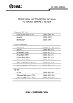
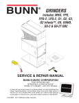
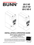
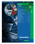
G9-2 HD
G9-2T HD
G9-2 HD-S
OPERATING & SERVICE MANUAL
BUNN-O-MATIC CORPORATION
POST OFFICE BOX 3227
SPRINGFIELD, ILLINOIS 62708-3227
PHONE: (217) 529-6601 FAX: (217) 529-6644
To obtain the Illustrated Parts Catalog, visit the Bunn-O-Matic website, at www.bunn.com. This is absolutely FREE,
and the quickest way to obtain the catalog. Contact Bunn-O-Matic Corporation at 1-800-286-6070 to obtain a paper
copy of the required Illustrated Parts Catalog mailed via U.S. Postal Service.
10218.0000S 04/07
©1994 Bunn-O-Matic Corporation
www.bunn.com
CONTENTS
Introduction................................................................................ 2
Warranty..................................................................................... 2
User Notices............................................................................... 3
Electrical Requirements.............................................................. 4
Operating Controls..................................................................... 4
Initial Set-Up............................................................................... 4
Cleaning...................................................................................... 5
Coffee Grinding........................................................................... 5
Adjustments............................................................................... 6
Troubleshooting.......................................................................... 7
Service..................................................................................... 10
Wiring Diagram........................................................................ 22
INTRODUCTION
This equipment will store up-to six pounds of whole bean coffee in each of two hoppers and grind it to a preset grind
and amount into an awaiting funnel and filter from most commercial drip coffee brewers. The equipment is only for indoor
use on a sturdy counter or shelf. Adequate space must be available above the grinder to raise the lids when adding beans.
Use only with whole bean coffee.
The grind is preset at the factory to drip specifications as set forth by the United States Department of Commerce and
adopted by the Coffee Brewing Center of the Pan American Coffee Bureau. Adjustments may be made to alter both the
amount and grind from the factory setting.
BUNN-O-MATIC COMMERCIAL PRODUCT WARRANTY
Bunn-O-Matic Corp. (“BUNN”) warrants equipment manufactured by it as follows:
1) All equipment other than as specified below: 2 years parts and 1 year labor.
2) Electronic circuit and/or control boards: parts and labor for 3 years.
3) Compressors on refrigeration equipment: 5 years parts and 1 year labor.
4) Grinding burrs on coffee grinding equipment to grind coffee to meet original factory screen sieve analysis: parts and
labor for 3 years or 30,000 pounds of coffee, whichever comes first.
These warranty periods run from the date of installation BUNN warrants that the equipment manufactured by it will be
commercially free of defects in material and workmanship existing at the time of manufacture and appearing within the
applicable warranty period. This warranty does not apply to any equipment, component or part that was not manufactured
by BUNN or that, in BUNN’s judgment, has been affected by misuse, neglect, alteration, improper installation or operation,
improper maintenance or repair, damage or casualty. This warranty is conditioned on the Buyer 1) giving BUNN prompt
notice of any claim to be made under this warranty by telephone at (217) 529-6601 or by writing to Post Office Box 3227,
Springfield, Illinois 62708-3227; 2) if requested by BUNN, shipping the defective equipment prepaid to an authorized BUNN
service location; and 3) receiving prior authorization from BUNN that the defective equipment is under warranty.
THE FOREGOING WARRANTY IS EXCLUSIVE AND IS IN LIEU OF ANY OTHER WARRANTY, WRITTEN OR ORAL, EXPRESS
OR IMPLIED, INCLUDING, BUT NOT LIMITED TO, ANY IMPLIED WARRANTY OF EITHER MERCHANTABILITY OR FITNESS
FOR A PARTICULAR PURPOSE. The agents, dealers or employees of BUNN are not authorized to make modifications to
this warranty or to make additional warranties that are binding on BUNN. Accordingly, statements by such individuals,
whether oral or written, do not constitute warranties and should not be relied upon.
If BUNN determines in its sole discretion that the equipment does not conform to the warranty, BUNN, at its exclusive
option while the equipment is under warranty, shall either 1) provide at no charge replacement parts and/or labor (during
the applicable parts and labor warranty periods specified above) to repair the defective components, provided that this
repair is done by a BUNN Authorized Service Representative; or 2) shall replace the equipment or refund the purchase
price for the equipment.
THE BUYER’S REMEDY AGAINST BUNN FOR THE BREACH OF ANY OBLIGATION ARISING OUT OF THE SALE OF THIS
EQUIPMENT, WHETHER DERIVED FROM WARRANTY OR OTHERWISE, SHALL BE LIMITED, AT BUNN’S SOLE OPTION
AS SPECIFIED HEREIN, TO REPAIR, REPLACEMENT OR REFUND.
In no event shall BUNN be liable for any other damage or loss, including, but not limited to, lost profits, lost sales, loss of
use of equipment, claims of Buyer’s customers, cost of capital, cost of down time, cost of substitute equipment, facilities
or services, or any other special, incidental or consequential damages.
10218 051603
USER NOTICES
Carefully read and follow all notices on the grinder and in this manual. They were written for your protection. All notices on the
grinder are to be kept in good condition. Replace any unreadable or damaged labels.
WARNING
Use only on a properly protected circuit
capable of the rated load.
Electrically ground the chassis.
Follow national/local electrical codes.
Do not use near combustibles.
An extension cord, when used, must be shorter
than 20 feet if 16-gage 3-conductor wire, or
shorter than 10 feet if 18-gage 3-conductor wire.
#37881.0000
FAILURE TO COMPLY RISKS EQUIPMENT
DAMAGE, FIRE, OR SHOCK HAZARD
PERSONAL INJURY
HAZARD.
READ THE ENTIRE OPERATING MANUAL
INCLUDING THE LIMIT OF WARRANTY AND
LIABILITY BEFORE BUYING OR USING THIS PRODUCT
KEEP FINGERS AND
FOREIGN OBJECTS
OUT OF HOPPER
OR CHUTE OPENING.
20545-0000D 01/04 © 1990 Bunn-O-Matic Corporation
#05876.0000
#20545.0000
DISPENSE TIME
(SECONDS)
2
15
20
25
10
1
.4
3
30
32
HIGH
20
25
10
1
6
3.2
2
15
.4
6
3.2
4
30
32
HIGH
L OW
3
4
L OW
HIGH
HIGH
LEFT
RIGHT
LOW
LOW
WARNING
HAZARDOUS VOLTAGE
UNPLUG GRINDER
BEFORE REMOVING
#05942.0000
#25763.0000
10218 042707
ELECTRICAL REQUIREMENTS
This grinder has an attached cordset and requires 2-wire, grounded service rated 120 volts ac, 15 amp, single
phase, 60 Hz for 120V models and 230 volts ac, 10 amp single phase, 50 Hz for 230V models..
OPERATING CONTROLS
Off/On/Start Switch
OFF - (upper position) Switching to this position stops all operation of the grinder.
ON - (middle position) The switch will return to this position after a grind cycle has begun and
will remain in this position after grinding has ceased.
START - (lower, momentary position) Pressing the switch initiates a timed grind cycle.
Hopper Selector Switch
Left - Switching to this position allows beans to be dispensed from the
left hopper.
Right - Switching to this position allows beans to be dispensed from the
right hopper.
P633
Batch Selector Switch (Optional)
Urn - Switching to this position allows the correct amount of beans to be
dispensed when grinding a large batch.
CARAFE - Switching to this position allows the correct amount of beans
to be dispensed when grinding a small batch.
Dispense Timer
The dispense timer controls the amount of beans that will leave the hopper in a grind cycle. The timer can
be adjusted to dispense a different amount from each hopper. The scale is from 0.4 to 150.0 seconds. Refer to
the Adjustments section for timer setting chart (page 7).
INITIAL SET-UP
1. Open the top lid. Clear all foreign objects and shipping material from the
hopper compartment and the entrance to the grind chamber.
2. Remove the lower front inspection panel.
3. Plug-in the grinder.
4. Select either the right or left hopper with the selector switch. Do not press
the start switch.
5. If grinder has an analog timer, proceed to step 6. If grinder has a digital
timer, momentarily press the center (DISPLAY) button on the dispense timer
panel. The readout will indicate the present timer setting in seconds and will
remain displayed for five minutes.
6. Adjust the timer setting to obtain the desired amount of coffee for the selected
P596
hopper.
7. Repeat steps 4 thru 6 for the other hopper.
8. Fill the hopper compartments with whole bean coffee. (Capacity 6 pounds each). The grinder is now ready
for use.
10218 051603
CLEANING
The use of a damp cloth rinsed in any mild, non-abrasive, liquid detergent is recommended for cleaning
all surfaces on Bunn-O-Matic equipment. Care should be taken not to scratch the hopper or windows with any
abrasive material. Regular cleaning will keep your grinder looking new for years.
COFFEE GRINDING
P597
STEP 1
P598
STEP 2
P599
STEP 3
P600
STEP 4
P601
STEPS 5 & 6
1.
2.
3.
4.
Visually inspect the selected hopper for an ample supply of whole bean coffee.
Place a paper filter into the brew funnel. The filter must not be folded-over or tilted to one side.
Insert the funnel into the funnel rails and push until it stops.
Momentarily press the start switch. The grinding action will stop automatically after the preset amount of
ground coffee is dispensed into the funnel.
5. Remove the funnel from the grinder and level the bed of grounds by gently shaking.
6. The loaded funnel is now ready for use in any commercial drip coffee brewer according to the manufacturer’s
instructions.
10218 091599
ADJUSTMENTS
The grind can be set from very fine to very coarse. The amount may be adjusted for use in most commercial
coffee brewers. The following procedures should be used to make adjustments. A change in the burr adjustment
will also change the amount dispensed. Any adjustment of the burrs should be followed by an adjustment of the
timer.
Burr Adjustment
1. Unplug the grinder and empty all beans from the hoppers.
2. Plug-in the grinder, momentarily press the off/on/start switch to the “START”
(lower) position (with either hopper selected) and release, run a few grind
cycles until all of the coffee in the grind chamber is used-up.
3. Remove the upper front inspection panel.
4. Early Models only, loosen the burr adjustment screw from its locked position.
5. Early Models only, hand loosen the adjustment locking nut around the screw
approximately one turn.
6. Press the off/on/start switch to the “START” (lower) position and release,
slowly turn the adjusting screw in a clockwise direction until a metallic whine
is heard due to the rubbing of the grinding burrs. (It may be necessary to start
more than one grind cycle to obtain this sound.)
7. Make a mark with a pen on the decal to note the position of the arrow on the
grind adjustment screw.
8. The following settings approximately correspond to the CBC recognized grinds.
All are referenced from the arrow position noted in #7.
P581
P581
Early Models
E - FIN
ARS
E
O
C
B U NN
P1073
FINE GRIND: Rotate the adjusting screw 7 hash marks in a counterclockwise
direction.
Late Models
DRIP GRIND: Rotate the adjusting screw 8 hash marks in a counterclockwise
direction.
REGULAR (COARSE) GRIND: Rotate the adjusting screw 12 hash marks in a counterclockwise direction.
9. Early Models only, hold the adjusting screw in its set position with a screwdriver while tightening the lock
nut to a snug position by hand. Slightly loosen the adjusting screw and retighten it to its prior position. The
lock nut should now be tight against the burr housing front cover.
Timer Adjustment
1. Unplug the grinder and remove the lower front inspection panel.
2. Determine the grind setting. (The factory setting is drip, to determine other settings, refer to the previous
section.)
P595
DIGITAL TIMER
ANALOG TIMER
10218 051603
ADJUSTMENTS (cont.)
3. Use the table on the next page to find approximate timer setting for the grind and amount of coffee desired.
4. Plug-in the grinder. Select either the right or left hopper with the selector switch. Do not press the start
switch.
5. If grinder has an analog timer, proceed to step 6. If grinder has a digital timer, momentarily press the center
(DISPLAY) button on the dispense timer panel. The readout will indicate the present timer setting in seconds
and will remain displayed for five minutes.
6. Adjust the timer setting to obtain the desired amount of coffee for the selected hopper.
7. Verify the setting by weighing a few samples. Use the following table as an approximate guide only.
8. Repeat steps 4 thru 7 for the other hopper.
APPROXIMATE TIMER SETTINGS IN SECONDS
Weight
(ounces)
1.5
1.75
2.0
2.25
2.5
2.75
3.0
3.25
4.0
6.0
8.0
10.0
12.0
14.0
16.0
Fine
(7*)
Drip
(8*)
0.5
0.7
1.0
1.4
1.9
2.4
2.9
3.3
4.8
8.6
12.0
15.7
19.6
23.5
27.0
0.5
0.6
0.8
1.4
1.8
2.2
2.7
3.1
4.4
7.9
11.5
15.1
18.5
22.0
25.3
Regular
(12*)
0.5
0.6
0.8
1.2
1.6
2.0
2.5
2.9
4.0
7.5
10.9
14.1
17.5
20.9
24.3
*Hash mark settings. Refer to Adjustment-Burr section.
TROUBLESHOOTING
A troubleshooting guide is provided to suggest probable causes and remedies for the most likely problems
encountered. If the problem remains after exhausting the troubleshooting steps, contact the Bunn-O-Matic
Technical Service Department.
•
•
•
•
WARNING
•
•
•
•
Inspection, testing, and repair of electrical equipment should be performed only by qualified
service personnel.
All electronic components have ac voltage and dc voltage potential on their terminals. Shorting
of terminals or the application of external voltages may result in board failure.
Intermittent operation of electronic circuit boards is unlikely. Board failure will normally be permanent. If an intermittent condition is encountered, the cause will likely be a switch contact or a
loose connection at a terminal or crimp.
Make certain that all electrical connections are tight and isolated.
Exercise extreme caution when servicing electrical equipment.
Turn power OFF when servicing, except when electrical tests are specified.
Follow recommended service procedures.
Replace all protective shields or safety notices.
10218 051603
TROUBLESHOOTING (cont.)
Problem
Probable Cause
Remedy
Grinder will not start.
1. No power or incorrect voltage
(A) Plug-in the grinder.
(B) Check the voltage at the wall
outlet with a voltmeter. It must
be 120 volts ac for 120V models and
230 volts ac for 230V models.
2. Off/On/Start switch
(A) Momentarily press the Off/On/
Start switch to the “START” (lower)
position.
(B) Refer to Service - Off/On/Start
switch for testing procedures. See
page 11.
Grinder will not shut off.
3. Timer
Refer to Service - Timer for testing
procedures. See page 17.
4. Relay
Refer to Service - Relay for testing
procedures. See page 14.
5. Motor overload protector
Remove the cover plate located
on the right side of the housing.
Press the red “Reset” button. Listen
carefully for a “click”. This resets
the motor protection circuit and
indicates that an overload may have
been encountered by the motor. (An
overload can occur when something
other than coffee is inserted into
the hopper for grinding.) Refer to
Service Motor for disassembly procedures. See page 12.
6. Motor
Refer to Service - Motor for testing
procedures. See page 12.
1. Off/On/Start switch
(A) Place the switch in the “OFF/
STOP” position.
(B) Refer to Service - Off/On/Start
Switch for testing procedures. See
page 11.
2. Timer
Refer to Service - Timer for testing
procedures. See page 17.
3. Relay
Refer to Service - Relay for testing
procedures. See page 14.
10218 031603
TROUBLESHOOTING (cont.)
Problem
Probable Cause
Remedy
Grinder starts, but will not dispense from either hopper.
1. Hoppers
Begin each grind cycle by visually
inspecting the hoppers for ample
supplies of whole bean coffee.
2. Bottoms of hoppers
3. Off/On/Start switch
Foreign materials must not block
the openings at the bottom of the
hoppers.
Refer to Service - Off/On/Start
switch for testing procedures. See
page 11.
(A) Check to see that the slide plates
move freely to allow beans to travel
into the grind chamber.
4. Slide plates
(B) Refer to Service -Slide Plates
for testing procedures. See page
15.
Timer will not display or displays
incorrectly.
5. Solenoids
Refer to Service - Solenoids for testing procedures. See page 16.
6. Shear plate
Refer to Service - Grind Chamber
for replacement procedures. See
page 13.
7. Solenoid Limit Thermostat
Refer to Service - Solenoids for
testing procedures. See page 16.
1. Digital Timer
(A) Unplug the grinder. Wait a few
seconds and plug it in again.
(B) Refer to Service - Timer for testing procedures. See page 17.
Incorrect amount of coffee.
Incorrect coffee grind dispensed.
1. Timer adjustment
Refer to the Adjustments section.
See page 6.
2. Snubber
Refer to Service - Snubber for replacement procedures. See page
16.
1. Burr adjustment
Refer to the Adjustments section.
See page 6.
10218 091599
SERVICE
This section provides procedures for testing and
replacing various major components used in this
grinder should service become necessary. Refer to
Troubleshooting for assistance in determining the
cause of any problem.
WARNING
Use only on a properly protected circuit
capable of the rated load.
Electrically ground the chassis.
Follow national/local electrical codes.
Do not use near combustibles.
WARNING - Inspection, testing, and repair of electrical equipment should be performed only by qualified
service personnel. The grinder should be unplugged
when servicing, except when electrical tests are required and the test procedure specifically states to
plug-in the grinder.
An extension cord, when used, must be shorter
than 20 feet if 16-gage 3-conductor wire, or
shorter than 10 feet if 18-gage 3-conductor wire.
FAILURE TO COMPLY RISKS EQUIPMENT
DAMAGE, FIRE, OR SHOCK HAZARD
READ THE ENTIRE OPERATING MANUAL
INCLUDING THE LIMIT OF WARRANTY AND
LIABILITY BEFORE BUYING OR USING THIS PRODUCT
20545-0000 7/90 © 1990 Bunn-O-Matic Corporation
NOTICE
For connection to Bunn-Omatic
Coffee Brewer Models:
Dual, OT, Single, & System III only.
(24 volt N.E.C. Class 2 circuit only.)
BUNN
MANUFACTURED BY BUNN-O-MATIC CORPORATION
SPRINGFIELD, ILLINOIS, U.S.A.
MODEL
S/N
VOLTS A.C.
AMP
WATTS
PHASE
WIRE
HERTZ
COVERED UNDER ONE OR MOREOF THE FOLLOWING PATENTS :
ONE OR MORE OTHER PATENTS MAY BE PENDING
P604
The rear panel is attached with eight 8-32 slotted
head screws.
Component Access
WARNING - Unplug the grinder before the removal of
any panel or the replacement of any component.
All components are accessible by the removal of
the upper and lower front inspection panels, hopper
assembly, and rear panel.
P605
The hopper assembly is attached with four 6-32
slotted head screws with locking nuts located on the
sides of the housing near the center and rear. Removal
of the hopper will also require disconnection of the
solenoid wires from the grinder wiring harness.
P602
The upper front inspection panel is attached with
two 6-32 slotted head screws.
Contents
Off/On/Start Switch...............................................11
Motor....................................................................12
Relay ....................................................................14
Slide Plates...........................................................15
CAUTION
PERSONAL INJURY
HAZARD.
KEEP FINGERS AND
FOREIGN OBJECTS
OUT OF HOPPER
OR CHUTE OPENING.
Snubber................................................................16
Solenoids..............................................................16
P603
Timer....................................................................17
The lower front inspection panel is attached with
two 6-32 slotted head screws.
Hopper Selector Switch........................................20
Batch Selector Switch...........................................21
10
10218 042707
SERVICE (cont.)
6. Check for continuity across the right terminals
when the switch is placed in the “START” (lower)
position only. Continuity must not be present in
the “OFF” position.
Off/On/Start Switch
If continuity is present as described, the Off/On/Start
switch is operating properly.
If continuity is not present as described, replace the
switch.
Removal and Replacement:
1. Remove all wires from the switch terminals.
2. Compress the clips inside the front wrapper and
gently push the switch through the opening.
3. Push the new switch into the opening and spread
the clips to retain the switch in the hood.
4. Refer to the following illustration when reconnecting the wires.
P594
Location:
The Off/On/Start switch is located to the left side
on the front of the housing above the upper front
inspection panel.
Test Procedure:
1. Unplug the grinder.
2. Remove the black wire from the switch.
3. Check for continuity across the black wire from
the Off/On/Start switch and the left blade of the
cordset connector (see illustration below).
VIO to timer P1-2
BLK to Cordset
BLK to timer P4-1
CORDSET CONNECTOR
Looking Strait-on
Black
WHI/RED timer to P4-6
BLU to SW2
PNK to Intf conn. 2
White
Grinders with Digital Timer
Ground
If continuity is present as described, proceed to #4.
If continuity is not present as described, refer to the
Wiring Diagrams and check the grinder wiring harness.
VIO to timer P1-2
BLK to Cordset
WHI/RED timer to P4-6
BLK to timer P4-1
4. Remove the remaining wires from the switch.
5. Check for continuity across the left terminals when
the switch is placed in both the “ON” (center) and
“START” (lower) positions. Continuity must not be
present in the “OFF” position.
BLU to SW2
PNK to Intf conn. 2
Grinders with Analog Timer
If continuity is present as described, proceed to #6.
If continuity is not present as described, replace the
switch.
OFF/ON/START SWITCH
11
P606
10218 091599
SERVICE (cont.)
Removal and Replacement - MOTOR
1. Remove all wires from the solenoids and lift the
hopper assy out of the grinder housing.
2. Remove all wires from all switches, motor, and
motor mounting plate.
3. The entire wiring harness must be fed into the
bottom of the grinder housing through the hole
in the motor mounting plate.
4. Remove both 6-32 screws beneath the upper front
inspection panel.
5. Remove the six 10-32, slotted, hex head screws
on top of the motor mounting plate.
6. Slowly slide the assembly out the rear of the
grinder housing. The mounting plate may have to
be raised to gain clearance for the motor hardware
and wiring harness bushing.
7. Remove the four 5/16”-18 bolts and nuts to separate the motor from the mounting plate.
8. Mount the new motor and tighten the four bolts
and nuts. They should be tightened approximately
one full turn past snug.
9. Slide the motor mounting plate into the rear of the
grinder housing.
10. Feed the wiring harness into the top of the housing
through the hole in the motor plate.
11. Reinstall the six 10-32 hex head screws through
the motor plate and the two 6-32 slotted head
screws through the housing.
12. Reattach the green wire to the 10-32 stud on the
motor mounting plate.
13. Refer to the Off/On/Start Switch, Hopper Selector
Switch and Batch Selector Switch sections when
reconnecting the switch wires.
14. Refer to the Solenoid section when reconnecting
the solenoid wires.
15. Refer to the following illustration when reconnecting the wires.
Motor
P607
Location:
The motor is located in the upper wrapper.
Test Procedure:
1. Remove the cover plate located on the right side of
the housing. Press the red “Reset” button visible
through the opening. Listen carefully for a “click”.
This resets the motor protection circuit and may
indicate that something other than coffee was
inserted into the hopper for grinding.
If the grinder remains unable to start, proceed to #2.
If the grinder stops operating shortly after starting,
refer to the removal and replacement steps to gain
access to the grind chamber. Remove any foreign
materials that may be found.
2. Unplug the grinder.
3. Remove the electrical access panel at the rear of
the motor.
4. Connect a voltmeter across terminals L1 & L2 of
the motor. Plug-in the grinder. Momentarily press
the Off/On/Start switch to the “START” (lower)
position and release. The indication must be 120
volts ac for 120V models and 230 volts ac for 230V
models.
5. Unplug the grinder
If voltage is present as described and the grinder
remains unable to start, replace the motor.
If voltage is not present as described, refer to the Wiring Diagrams, and check the grinder wiring harness.
12
10218 051603
SERVICE (cont.)
Motor (cont.)
WHI/ BLU to Snubber
WHI/BLU to Relay
WHI/BLK to Cordset
(120V models)
RED/BLK to Cordset
(230V models)
WHI/BLK to Snubber
GRN to Chasis Ground
YEL to Snubber
FRANKLIN MOTOR
WHI/BLK to Snubber
YEL to Snubber
WHI/ BLU to Snubber
WHI/BLK to Cordset
MARATHON MOTOR
WHI/BLU to Relay
GRN to Chasis Ground
P621
Removal and Replacement - GRIND CHAMBER
1. Remove the two 1/4”-20 screws holding the front
cover to the burr housing. Carefully remove the
burr housing front cover. Inspect the adjusting
screw to see if the thrust plug is worn.
Replace if excessively worn or damaged.
2. Carefully remove the rotor cup, shear plate, and
burr rotor from the grinder. Inspect the shear plate
and burrs for wear.
Replace if excessively worn or damaged.
3 Remove and inspect the stationary burr for
wear.
Replace if excessively worn or damaged.
4. Inspect the grind chamber and remove any foreign materials. The burrs will not properly seat
in the chamber if any material or coffee particles
remain.
5. Reinstall the stationary burr, burr rotor, shear plate,
rotor cup, and dial plate to the burr housing.
6. Refer to the Adjustments section to vary the grind
dispensed.
13
10218 051603
SERVICE (cont.)
If voltage is not present as described, refer to the Wiring Diagrams and check the grinder wiring harness.
Relay
DIS
E
NS
PE
ec
E (S
on
4. Remove the white/red and white/blue wires from
the relay contacts.
5. Check for continuity across the relay contacts
when the Off/On/Start switch is pressed to the
“START” (lower) position and released. Plug-in
the grinder. Continuity must be present for the
approximate setting on the timer.
6. Unplug the grinder.
)
ds
TIM
DIS
e
reas
Dec
Y
PLA
utes
min
r5
d fo sted
laye adjuyed.
disp be la
be only disp
will can t is
ut
ou
do mer ad
GE
Rea Tihile re
TA
w
OL
se
ea
.
Incr
+
N IN
AR S V
G
W DOU
R
ZA
HA
If continuity is present as described, reconnect the
white/red and white/blue wires, the relay is operating
properly.
If continuity is not present as described, replace the
relay.
ER
IND G
GR VIN
G MO
PLU RE
UN RE
FO
BE
Grinders with Digital Timer
E
IM
ET
NS DS)
PE ON
DIS(SEC
10
2
20
15
.4
32
6
3.2
1
3.2
HI
4
LO
W
GH
OFF
GH
ON
T
W
GAGE
INLT
O
RN
SV
WA
OU
RD
ZA
HA
ON
LO
30
LO
FT
LE
3
25
32
HI
RI
W
GH
OFF
20
H
HI G
4
H
HI G
LO
2
15
6
.4
30
10
1
3
25
Removal and Replacement
1. Remove all wires from the relay terminals.
2. Remove the 6-32 screw fastening the relay to the
timer bracket.
3. Mount the new relay to the timer bracket and
tighten the screw.
4. Refer to the following illustration when reconnecting the wires.
W
R
DE G
IN
GR VIN
G MO
PLU RE
UN RE
FO
BE
Grinders with Analog Timer
P609
Location:
The relay is located on the timer bracket in the
grinder base. The bracket can be removed by loosening the two 8-32 slotted head screws beneath the timer
dial.
WHI/BLU to
Motor L1
Test Procedure:
1. Unplug the grinder.
2. Connect a voltmeter across the red/black and
white/green wires of the relay coil. Plug-in the
grinder. Momentarily press the Off/On/Start switch
to “START” (lower) position and release. The indication must be 120 volts ac for 120V models and
230 volts ac for 230V models for the approximate
setting on the timer.
3. Unplug the grinder.
RED/BLK to
Timer P4-7
WHI/RED to
Timer P4-6
WHI/GRN to
Timer P4-3
P610
If voltage is present as described, reconnect the
red/black and white/green wires to the relay coil, and
proceed to #4.
14
10218 051603
SERVICE (cont.)
Slide Plates
M.
A.
B.
C.
J.
D.
I.
E.
K.
F.
L.
G.
H.
A.
B.
C.
D.
E.
F.
G.
H.
I.
J.
K.
L.
M.
Solenoid Coil
Fiber Washer
Spring
Spring Retaining Washer
Solenoid Plunger
Snap Ring
Short Link
Long Link
Slide Plate
Pivot Pin
Stop Block
Solenoid Mounting Plate
Solenoid Limit Thermostat
P608
Location:
The slide plates are located on the solenoid mounting plate immediately beneath the hopper openings.
The slide plates must always remain flat for
proper operation.
Removal and Replacement:
1. Remove the hopper from the grinder.
2. Remove six slotted head screws holding the solenoid mounting panel to the hopper.
3. The slide plate with attached linkage can be lifted
off the pivot pin and removed with the solenoid
plunger.
4. Refer to the illustration above when reassembling
the components.
5. Inspect the slide plates after reassembly.
They must move freely.
Test Procedure:
With the solenoid mounting plate attached to the
hopper, push the solenoid plunger into the coil. The
slide plate must move freely in the assembly and snap
closed when the plunger is released. Repeat for the
other slide plate.
If the slide plates move as described, they are
operating correctly.
If the slide plates do not move as described, the
problem may be in any one or more of the linkage
pieces, springs, slide plates, and/or the solenoid
mounting plate. Disassemble the solenoid mounting
plate assembly and inspect all components for free
movement.
Replace if excessively worn or damaged.
15
10218 091599
SERVICE (cont.)
Solenoids
Snubber
BLY
E
FIN
EMPT UG
THORO
F T
O H
R IS
E
C
R OV
EA E
SS R.
EM
SE
AR
CO
E NG
COVRI BE
NOTI
Y
EM E
H
HL OPPER BEFORE RAMB
YC
LEAN GRIND CH
P611
Location:
The snubber is located at the back of the motor
attached to the right side of the wiring harness.
P608
Removal and Replacement:
1. Remove snubber wires from the motor terminals.
2. Cut the ties holding snubber to the wiring harness.
3. Refer to the following illustration when reconnecting the wires.
4. Fasten snubber to the wiring harness using new
ties.
Location:
The solenoids are located on the mounting plate
immediately beneath the hoppers.
Test Procedure:
1. Unplug the grinder.
2. Connect a voltmeter across the left or right solenoid coil terminals. Plug-in the grinder. Momentarily press the Off/On/Start switch to “START”
(lower) position and release (hopper selector
switch must be corresponding to the suspect
solenoid). The indication must be 120 volts ac for
120V models and 230 volts ac for 230V models.
3. Unplug the grinder.
WHI/ BLU to Snubber
WHI/BLU to Relay
WHI/BLK to Cordset
(120V models)
RED/BLK to Cordset
(230V models)
If voltage is present as described, proceed to #4.
If voltage is not present as described, refer to the Wiring Diagram and check the grinder wiring harness.
WHI/BLK to Snubber
GRN to Chasis Ground
YEL to Snubber
4. Separate the connectors on the white/brown
wires of the solenoids from the connectors on the
grinder wiring harness (RED/BLK) and the limit
thermostat.
5. Check for continuity across the white/brown wires
on the suspect solenoid coil.
FRANKLIN MOTOR
WHI/BLK to Snubber
YEL to Snubber
WHI/ BLU to Snubber
WHI/BLK to Cordset
MARATHON MOTOR
WHI/BLU to Relay
GRN to Chasis Ground
P621
16
10218 051603
SERVICE (cont.)
WHI/YEL to
Timer P4-5
RED/BLK to
Right Solenoid
RED/BLK to
Timer P4-7
Solenoid(s) (cont.)
If continuity is present as described, reconnect the
white/brown wires to the grinder wiring harness, and
proceed to #6.
If continuity is not present as described, replace the
solenoid.
RED/BLK to
Left Solenoid
WHI/ORN to
Timer P4-4
6. Check for continuity across the terminals of the
limit thermostat.
Right
Left
If continuity is present as described, reconnect the
wires, and proceed to #7.
If continuity is not present as described, replace the
limit thermostat.
P612
Timer
7. Check the solenoid for coil action when the control
switch is momentarily pressed to the “START”
(lower) position and released. Plug-in the grinder.
Listen carefully in the vicinity of the solenoid for a
“clicking” sound as the coil magnet attracts and
after a period of time, repels the plunger.
8. Unplug the grinder.
DIS
PE
NS
E (Se
E TIM
DIS
co
s)
nd
De
AY
cre
e
as
s.
ute
rea
5 min
for ted
yed jus .
pla ad yed
dis ly be pla
l be on is dis
t wil can ut
ou
do
E
ad Timer rea
AG
ile
wh
Inc
+
Re
PL
se
G
IN
R N VOLT
WAOUS
RD
ZA
HA
ER
IND G
GR VIN
UG MO
PL RE
UN RE
FO
BE
Digital Timer
If the sound is heard as described and the plunger
remains unable to move or move freely, refer to the
slide plate section.
If the sound is not heard as described, replace the
solenoid.
TIME
SE S)
EN ND
SP
DI (SECO
10
2
20
15
1
.4
32
6
3.2
.4
3
25
30
32
4
LOW
OFF
ON
HT
RIG
LOW
H
ON
20
H
HIG
H
HIG
LOW
OFF
2
15
6
3.2
4
H
HIG
HIG
Removal and Replacement:
1. Remove the hopper assy from the grinder.
2. Remove the four 8-32 slotted-head screws holding
the solenoid coil to the solenoid panel.
3. Feed the white/brown wires through the hole in
the solenoid mounting plate and loosely install
the new solenoid coil.
4. Look through the collector on the bottom of the
assy and adjust the slide plate travel distance when
installing the solenoid coil.
5. Push the solenoid plunger into the solenoid coil
with your hand while moving the coil forward or
backward in its mounting holes.
6. Securely tighten the mounting screws when the
slide plate appears to have no metal showing in
the front or back of the hopper hole.
7. Refer to the following illustration when reconnecting the wires.
1
3
25
30
10
T
LEF
G E
INLTAG
R N VO
WAOUS
RD
ZA
HA
LOW
ER
IND G
GR VIN
UG MO
PL RE
UN RE
FO
BE
Analog Timer
P613
Location:
The timer is located in the grinder base.
Test Procedure:
1. Unplug the grinder.
2. Connect a voltmeter across contacts 1 & 2 of the
larger connector (P4) on the timer board. Plug-in
the grinder. The indication must be 120 volts ac for
120V models and 230 volts ac for 230V models.
3. Unplug the grinder.
17
10218 0516030
SERVICE (cont.)
Timer (cont.)
4. Connect a voltmeter across contacts 2 & 6 of the
larger connector (P4) on the timer board. Plugin the grinder. When the control switch is in any
position except “OFF” (center), the indication must
be 120 volts ac for 120V models and 230 volts ac
for 230V models.
5. Unplug the grinder.
10. Connect a voltmeter across contacts 5 & 7 of the
larger connector (P4) on the timer board. Plug-in
the grinder. Place the hopper selector switch to
the right position. Momentarily press the Off/On/
Start switch to the “START” (lower) position and
release. The indication must be 120 volts ac for
120V models and 230 volts ac for 230V models
and should remain for the approximate timer setting.
11. Unplug the grinder.
If voltage is present as described, proceed to #6.
If voltage is not present as described, refer to the Wiring Diagram and check the grinder wiring harness.
If voltage is present as described, the timer is operating properly.
If voltage is not present as described, replace the
timer.
6. Connect a voltmeter across contacts 3 & 7 of the
larger connector (P4) on the timer board. Plug-in
the grinder. Momentarily press the Off/On/Start
switch to “START” (lower) position and release.
The indication must be 120 volts ac for 120V
models and 230 volts ac for 230V models.
7. Unplug the grinder.
Removal and Replacement:
1. Separate the grinder wiring harness connectors
from the timer circuit board.
2. Remove the relay from the timer bracket.
3. Attach the relay to the new timer bracket.
4. Refer to the following illustration when reattaching
the connectors.
5. Refer to the Adjustments section to reset the
volume dispensed.
If voltage is present as described, proceed to #8.
If voltage is not present as described, replace the
timer.
8. Connect a voltmeter across contacts 4 & 7 of the
larger connector (P4) on the timer board. Plug-in
the grinder. Place the hopper selector switch to
the left position. Momentarily press the Off/On/
Start switch to the “START” (lower) position and
release. The indication must be 120 volts ac for
120V models and 230 volts ac for 230V models
and should remain for the approximate timer setting.
9. Unplug the grinder.
If voltage is present as described, proceed to #10.
If voltage is not present as described, replace the
timer.
18
10218 051603
SERVICE (cont.)
Timer (cont.)
Digital Timer
Analog Timer
P614
19
10218 051603
SERVICE (cont.)
Hopper Selector Switch
Removal and Replacement:
1. Remove all wires from the switch terminals.
2. Compress the clips inside the front of the housing
and gently push the switch through the opening.
3. Push the new switch into the opening and spread
the clips to retain the switch in the housing.
4. Refer to Fig. below when reconnecting the
wires.
P594
HOPPER SELECTOR SWITCH
Location:
The hopper selector switch is located in the center
on the front of the hopper housing.
Test Procedure:
1. Disconnect the grinder from the power source.
ORA to Timer P1-6
2. Remove all wires from the switch terminals.
BLU to Timer P1-8
3. Place the selector switch in the left position.
YEL to Timer P1-1
4
Check for continuity across the center and right
terminals on the rear of the switch.
P787
HOPPER SELECTOR SWITCH TERMINALS
5. Continuity must not be present across the center
and left terminals on the rear of the switch.
6. Check the bottom row, then the top row of terminals.
If continuity is present as described proceed to #7.
If Continuity is not present as described replace the
switch.
7. Place the selector switch in the right position.
8. Check for continuity across the center and left
terminals on the rear of the switch.
9. Continuity must not be present across the center
and right terminals on the rear of the switch.
10.
Check the bottom row, then the top row.
If continuity is present as described, reconnect the
wires, the switch is operating properly.
If continuity is not present as described, replace the
switch.
20
10218 091599
SERVICE (cont.)
Batch Selector Switch (Models w/Multi-Set option)
Removal and Replacement:
1. Remove all wires from the switch terminals.
2. Compress the clips inside the front of the housing
and gently push the switch through the opening.
3. Push the new switch into the opening and spread
the clips to retain the switch in the housing.
4. Refer to Fig. below when reconnecting the
wires.
BATCH SELECTOR SWITCH
P594
GRN to Timer P1-3
BLU to Timer P1-8
Location:
The Batch Selector Switch is located in the lower
right front of the hopper housing.
Test Procedure:
1. Disconnect grinder from the power supply.
P1038
2. Remove all wires from the switch terminals.
BATCH SELECTOR SWITCH TERMINALS
3. Check that the switch is installed properly.
4. Place the selector switch in the left position.
5. Check for continuity across the terminals on the
rear of the switch.
If continuity is present as described proceed to #6.
If continuity is not present as described, replace the
switch.
6. Place the selector switch in the right position.
7. Check for continuity across the terminals on the
rear of the switch. Continuity should not be present
across terminals in the right position.
If continuity is not present as described, reconnect
the wires, the switch is operating properly.
If continuity is present replace the switch.
21
10218 091599
WIRING DIAGRAM
22
10218 051603
SCHEMATIC WIRING DIAGRAM G9-2A HD
L1
OFF/ON/START
SW
BLK
PNK
BLU
HOPPER
SELECTOR SW
BLU
LT
RT
OPTIONAL
MULTI-SET SW
BLU
BLK
230 VOLTS AC
2 WIRE
SINGLE PHASE
50 HZ
YEL
P1
VIO
GRN
GRY
TAN
ORA
BLU
1
GRN/YEL
P4
TIMER
1
8
RED/BLK
WHI/GRN
WHI/ORA
WHI/YEL
L2
WHI/BLK
WHI/BLK
8
BLK
WHI/RED
RT
LT
SOL
2
SOL
1
GRINDER INTERFACE
CONNECTOR
4
GRY
3
PNK
2
TAN
1
K1
WHI
WHI/BLU
YEL
SNUBBER
WHI/BLK
WHI/RED
WHI/BLU
K1 N.O.
L1
M
RED/BLK
L2
10768.0000E 05/03 © 1993 BUNN-O-MATIC CORPORATION
23
10218 051603