1
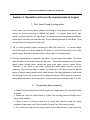
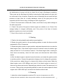
O P E R AT I O N & M A I N T E N A N C E M A N U A L
SERIE DIESEL ENGIEN
O P E R AT I O N & M A I N T E N A N C E M A N U A L
YANGDONG CO., LTD
1
O P E R AT I O N & M A I N T E N A N C E M A N U A L
Foreword
Series Yangdong multi-cylinder diesel engines are ideal power units for light vehicle,
agro motor, small tractor, air conditioner in bus, generator set and engineering
machinery.
The normal and reliable operation and long service life of the engine depend not only
on the manufacturing quality, but also on the reasonable operation and correct
maintenance.
In order to provide the detailed description and instruction of this engine for operators
to manipulate it correctly in short time, we offer this manual which briefly describes the
performance of series Yangdong diesel engines to operators, maintenance workers and
relevant mangers.
Since the construction of this engine is subject to frequent improvement and
development during production and practice, it is possible that the engine supplied is
somewhere not exactly the same as one described herein. Please pay attention to that
when reading the manual.
Warning Notice
1,It is strictly forbidden to use inferior and dirty diesel fuel or lube oil. Please choose to use fuel and
lube oil with stipulated number according to the instruction.
2,It is strictly forbidden to leak out from an intake system (air filter, pipelines and connecting
components)
3, It is strictly forbidden to have hard water (well water or sopring water)as cooling water, if necessary
to apply the hard(water),soften it first.
4, It is strictly forbidden to start under the circumstances of lack of lube oil or water
5, It is strictly forbidden to operate at overload or under other conditions against the rules
6, It is strictly forbidden to regulate the fuel injection pump at will
7, It is strictly forbidden to change the diameter of the pulley
8,To control the starting time(less than 15 seconds) and the starting interval(more than 2
minutes)strictly
9, It’s must to maintain the diesel engine technically in the allotted time
2
O P E R AT I O N & M A I N T E N A N C E M A N U A L
10, ambient temperature under 0°C, discharge all the coolant to prevent frostbite after stop
11, all the filters(include air pump filter ) maitain,repair or instead according to the provision
Notice of winter
Make sure the usual running of engine; please pay attention the items as following:
1、please use “-10#”light diesel oil
2、please use Class CC or CD 10W/30 or 5w/30 diesel fuel, and the Class CD diesel fuel for
turbine charger
3、Make sure the connecting reliable and available between battery and start motor
Battery capacity should be conform to specification of manual
The total length of front line, ground line should less2 meters, and area more than 40 mm2
The total length of front line, ground line should more than 2 meters, and area more than 70
mm2
4、The temperature starting should be below -5°C,and add hot water and fuel
5、Eliminate the air of fuel system
6、Check if the pulverization of injector is normal or no
3
O P E R AT I O N & M A I N T E N A N C E M A N U A L
Contents
1, Configuration and Installation dimension of model YSD490ZL (Fig.1)
2, Performance Curves of Model YSD490ZLD (Fig.2)
Section 1. Diesel engine specification and technical dates
1、specification of diesel engine
… ………………………………………………1-1
2、specification of the main accessories
………………………………………………1-4
3、Main technical data of diesel engines
…………………………………………1-7
4、Fit clearance and wear limit of main parts …
………………………………………1-8
Section 2. Operation and security requirements of engine
1、Fuel oil 、lube oil and cooling water
2、Preparation before starting
3、Starting
……………………………………………2-1
… …………………………………………………………2-1
………………………………………………………………………………2-2
4、Running
……………………………………………………………………………2-2
5、Stopping
…………………………………………………………………………2-3
6、Security requirements
……………………………………………………………………2-3
Section 3 Maintenance
1、Routine maintenance
……………………………………………………………………3-1
2、Maintenance after 100 accumulated operating hours
………………………………3-1
3、Maintenance after 500 accumulated operating hours
………………………………3-2
4、Preservation and storage of engine
………………………………………………………3-3
Section 4 Engine adjustment
1、adjustment of valve lash ………………………………………………………………………4-1
2、adjustment of injection timing
………………………………………………………………4-1
3、adjustment of injector …………………………………………………………………………4-2
4、adjustment of lube oil pressure … ……………………………………………………………4-3
4
O P E R AT I O N & M A I N T E N A N C E M A N U A L
5、adjustment of injection pump …………………………………………………………………4-3
6、adjustment of decompression arm lash ……………………………… ……………………4-3
Section 5 Construction of diesel engine
1、cylinder head
…………………………………………………………………5-1
2、cylinder block
………………………………………………………………………………5-2
3、piston 、connecting rod …
4、crankshaft and flywheel
5、camshaft ……
…………………………………………………………………5-2
……………………………………………………………………5-4
……………………………………………………………………………………5-4
6、gear transmission system…………………………………………………………………………5-4
7、fuel and governing system
8、lubrication system
9、cooling system
10、electric system
… …… ……………………………………………………………5-5
… ………………………………………………………………………5-6
…………………………………………………………………………………5-6
… ………………………………………………………………………………5-7
Section 6 Operation notice of turbo- charger diesel engine
Section 7
……………………………6-1
faults and remedies for diesel engine
1、hard or refuse to start
2、power insufficiency
……………………………………………………………7-1
………………………………………………………………………7-1
3、smoking exhaust
……………………………………………………………………7-1
4、knocking noise in engine
……………………………………………………………………7-2
5、lube oil insufficiency or no pressure
6、overheating of engine
7、engine running-away
……………………………………………………………7-2
……………………………………………………………………7-2
………………………………………………………………………7-2
Section 8 The faults diagnose of diesel engine turbo-charger
Section 9 The faults diagnose list of turbo-charger
……………………………8-1
…… ……………………………………9-1
Appendix:
Wearing parts order sheet
5
O P E R AT I O N & M A I N T E N A N C E M A N U A L
6
O P E R AT I O N & M A I N T E N A N C E M A N U A L
7
O P E R AT I O N & M A I N T E N A N C E M A N U A L
8
O P E R AT I O N & M A I N T E N A N C E M A N U A L
Chart 7. the load characteristic curve of YSD490ZLD
Section 1. Diesel engine specification and technical dates
1、specification of diesel engine
Model
Type
YSD490ZLD
line、water cool 、four stroke、direct
combustion chamber
Cylinder No.
4
Bore(mm)
90
Stroke(mm)`
100
Compression ratio
18
Total displacement(L)
2.54
Firing order
Related power(kw)
Related speed(r/min)
1-3-4-232
38.4
1500
1800
Fan diameter(mm)
410
Advance injection fuel Angle(Before )(°CA)
6±1
Min.specific fuel consumption at full load (g/kw.h)
≤225
Oil-fuel consumption ratio(g/kW.h)
Direction of crankshaft rotation(facing to flywheel)
≤2.72(the condition of out of factory
counterclockwise
cooling methods
Forced water cooling
lubricating methods
Pressure and splash
lubrication
Starting methods
electric
9
O P E R AT I O N & M A I N T E N A N C E M A N U A L
Net mass(kg)
280
Dimension (L×W×H)(mm)
733×628×610
2, specification of the main accessories
Name
No.
Type
1
Fuel
injection
pump
Governor
Plunger
diameter(mm)
Fuel delivery
pump
model
Nozzle set
2
Fuel
injector
Diameter of
nozzle hole
(
)
Injection
pressure(Mpa)
3
4
5
6
Lube
pump
Water
pump
Starting
motor
Alternator
Specification
Y385
Y485
Series I or BQ pump
All-speed,mechnical centrifugal
7
Single-acting piston-type
00P21-15N
ZS4S1
1
13.2±0.5
Model
Rotor type
speed(r/min)
1300
capacity(L/min)
18
Pressure (kpa)
400
Model
Centrifugal, volute, single-suction
speed(r/min)
3000
capacity(L/min)
80
Type
Silicon rectifying shunt dynamo
Model
QD1322、QD1315A、D138Y、QD138C
Voltage(V)
12
power(KW)
1.8 或 2.5
Type
Brushless alternator
10
O P E R AT I O N & M A I N T E N A N C E M A N U A L
7
Fuel filter
8
Lube oil
filter
9
Model
JF13 或 JF15
Voltage (V)
14
Power (W)
350 或 500
Type
Single stage, paper element
Model
C0506A
Type
Single stage, paper element
Model
J0708 或 J0810 或 J0810H
Type
Oil-immersed
Model
K1317A 或 CN212
Air filter
1-4
Name
NO.
Specification
YD480
YSAD380
Series I or BQ pump
Type
1
Fuel
injection
pump
All-speed,mechnical centrifugal
Governor
Plunger
7.5
7.5
Fuel delivery
2
3
4
5
6
Fuel
injector
Lube
pump
Water
pump
Starting
motor
Alternator
YND485
Single-acting piston-type
model
P78-1
P78-1
PF68509
Nozzle set
Diameter of
l h l
Injection
ZCK154S423
ZCK154S423
ZCK154S425
Model
speed
(
/ i )
capacity
4-φ0.23
4-φ0.25
19.6 +1,0
Rotor
Gear
1300
2748
18
22.4
(L/
i )
Pressure
(k )
Model
speed
(
/ i )
capacity
Centrifugal, volute, single-suction
(L/ i )
Type
series shunt DC motor
Model
QD1315A、D138Y
Voltage(V)
12
power(KW)
2.5
Type
Silicon rectifying shunt dynamo
400
3000
4000
80
160
11
O P E R AT I O N & M A I N T E N A N C E M A N U A L
7
Fuel filter
8
Lube oil
filter
9
Air filter
Model
JF11 或 JFW13 或 JFW15
Voltage (V)
14
Power (W)
350 或 500
Type
Single stage, paper element
Model
C0506A
Type
Single stage, paper element
Model
J0708 或 J0810 或 J0810H
Type
Oil-immersed
Model
Name
NO.
Type
1
2
3
Fuel
injection
pump
Fuel
injector
Lube
pump
4
Water
pump
5
Starting
motor
6
Alternator
Governor
K1317A
Specification
YSD490ZL
Series I or BQ pump
Single-acting piston-type
Plunger
Fuel delivery)
8
Single-acting piston-type
model
P78-1
Nozzle set
Diameter of
l h l
Injection
ZCK154S423
Model
Rotor pump
speed(r/min)
capacity
(L/
i )
Pressure
1300
(k
)
Model
Centrifugal, volute, single-suction
4-φ0.23
+1
19.6 ,0
18
400
speed(r/min)
3000
capacity
80
(L/
i
)
Type
series shunt DC motor
Speed down motor
Model
QD1315A 或 D138Y 或
QD2636A 或 QDJ2508F
Voltage(V)
12 或 24
power(KW)
2.5 或 4.5
Type
Silicon parallel shunt motor
Model
JFW13 或 JFW25
12
O P E R AT I O N & M A I N T E N A N C E M A N U A L
7
Fuel filter
8
Lube oil
filter
9
Air filter
Voltage (V)
14 或 28
Power (W)
350 或 500
Type
Single stage, paper element
Model
C0708B、CX0708B
Type
Single stage, paper element
Model
J0810、J0810H、J0814、JX0814
Type
Oil-immersed
Model
KW1532、K1526
3, Main technical Data of diesel engines
1. Valve lash(mm)
YSD490ZL
intake valve(cold )
0.30~0.35
exhaust valve(cold)
2. Sink age of valve
0.35~0.40
YSD490ZL
sink age of valve
0.7~0.9
3. torque limits of main bolts and nut(N.m)
cylinder head bolts
connecting rod bolts
main bearing cap bolts
flywheel bolts
clutch house bolts
crankshaft belt bolts
4. Temperature and pressure limit
YSD490ZL
125~145
100~120
140~160
100~120
90~120
200~260
YSD490ZL
exhaust temperature (°C)
≤590
(1)exhaust temperature(°C)
refer to above chart
(2)Cooling water temperature (°C) 80-95
≤100
(3)Lube oil temperature (°C)
(4)Lube oil pressure in main passage(MPa)
13
O P E R AT I O N & M A I N T E N A N C E M A N U A L
At normal operation
0.2~0.4
At min. steady speed
≥0.065
5. Governor characteristics
Min .Idling steady speed (r/min)
6. Oil sump capacity
≤900
steady regulation(%)≤5
YSD490ZL
oil sump
capacity
(L)
About 7
7. Battery (engine not include) capacity (A) ≥150
4、Fit clearance and wear limit of main parts
YSD490ZL
N0.
Name
Assembly limit
Wear limit
1
connecting rod journal and connecting rod 0.052~0.118
0.20
2
piston pin and connecting rod small end 0.025~0.048
0.10
3
piston skirt and cylinder liner
4
0.130~0.195
0.40
st
0.080~0.112
0.20
nd
clearance between the 1 ring and its groove
5
clearance between the 2 ring and its groove
0.030~0.065
0.18
6
clearance between the oil scraper and its 0.030~0.065
0.18
7
st
0.309~0.450
1.50
nd
gap of the 1 ring
8
gap of the 2 ring and oil scraper ring
0.250~0.400
1.50
9
crankshaft main journal and main bearing
0.070~0.154
0.25
10
camshaft journal and bushing
0.100~0.176
0.25
11
idle gear shaft journal and bushing
0.025~0.075
0.18
12
intake valve stem and valve guild
0.030~0.072
0.23
13
Exhaust valve stem and valve guild
0.040~0.082
0.24
14
rocker arm shaft and bushing
0.020~0.071
0.20
15
Axial clearance of crankshaft
0.070~0.262
0.40
16
Axial clearance of camshaft
0.080~0.260
0.50
14
O P E R AT I O N & M A I N T E N A N C E M A N U A L
Section 2. Operation and security requirements of engine
1, Fuel, lube Oil and Cooling water
1. Fuel. Users can choose diesel adopted according to local ambient temperature. In
China, we choose according to GB252 light diesel.
In summer adopt No.”0” light
diesel, in winter adopt No.”10” light diesel. The diesel must be a long time precipitation
before inject into tank (not less than 48h). During refueling should us cloth filters. Thus
can extended fuel pump and injector life.
2. Oil. In China generally adopt according to GB11122 Diesel Oil.
In summer adopt
No.CC40 diesel oil; in winter adopt No.30 diesel oil, used CD class diesel oil for turbo
diesel engine. Must filter through strainer when inject in to diesel engine.
3. Coolant. Applications of rainwater, tap water or clean water are suitable. The water
wells for water or well water should not be used.
If the water contains more minerals,
diesel engine cooling water system will have more scale, easy to cause failure.
Therefore, If you want to use wells, springs and other water sources, must be
softening. There are two ways to soften: (1) boiled (2) in 30 liters of water to add 20
grams of caustic soda (caustic soda), made solution. Can add antifreeze in cold winter.
Ant freezing Fluid is the most commonly used public glycol (TEG) aqueous or alcohol.
Diesel difficult to start in low temperature, cooling water can be heated to 80 °C to use.
2. Preparation before starting
1, Check if the joints that fix the diesel engine are reliable and if the operating handle
is flexible.
2, Rotate the crank for several times to check if the moving parts are flexible and if
there is any obstacle.
3, Check if the oil surfaces inside the oil sump and injection pump are within
regulated scale range, and if the oil tank is full and if the fule loop is smooth.
4, Turn on the fuel tank valve to check if there is are inside the loop, if yes; loosen the
15
O P E R AT I O N & M A I N T E N A N C E M A N U A L
discharge bolts of the diesel filter and injection pump. Then press handle pump on
the transmission oil pump until the air inside the oil loop is discharged completely.
Then screw up the discharge bolt before loosening the high pressure oil pipe joint
nut at the end of the oil injector. Rotate the rank to discharge the air inside the high
pressure oil pipe. After air is totally discharge, screw up the pipe joint nut and
meanwhile check if there is any oil leakage at each oil pipe joint.,
5, Check if the water tank is filled with coolant, and if there is any water leakage at
the water pipe joints.
6,Check if the joints of the parts of diesel engine are reliable or not. Check if the
storage battery is charged sufficiently, and if the joints of the lines of electric
appliance system are correct and reliable.
7, Check if the clutch is out of position.
3. Starting
1, Position the timing handle and medium speed position;
2, Rotate the ignition switch to the pre-heating position to make the thermo switch
preheated for 20 to 30 seconds;
3, Rotate the ignition switch to open position, and press the start button to make the
diesel engine start. If the diesel engine cannot be started, loosen the button right
away and wait for 2 to 3 minutes to restart it. If the diesel engine fails in starting for
three times successively, check the fault cause and eliminate the faults before
restart.
4, After the diesel engine is started, loosen the button, and rotate the ignition switch
to another position. Connect the generator charging circuit to charge the generator.
At the same time, adjust the gun to observe the rotation velocity meter. Make the
diesel engine runs in 600~800rpm and check if the diesel engine is normal or if
there are any abnormal sounds. Especially pay attention to see if the pressure of oil
is correct. Then pull the timing handle gradually to make the rotation speed of diesel
engine reach 1800~2000 rpm, and warm the machine without load.
4, Running
1, when the coolant temperature reaches 50°C and the oil temperature over 40°C,
working with load is permitted. When using normal conditions, the water temperature shall
16
O P E R AT I O N & M A I N T E N A N C E M A N U A L
reach about 80°C.
2, Increase or decrease of the diesel engine load and rotation speed shall be
carried out evenly and gradually. Under normal conditions, it is not allowed to add or
remove the load suddenly.
3. During the operation time of the diesel engine, pay attention often to seek if the
reading on the instruments on the instrument panel is normal. Pay attention to the
exhausted gas color and the operation sound. Stop the machine for inspection if
there is anything abnormal.
5、Stopping
1. Before diesel engine stopping, it should reduce the load speed gradually to make
the speed at 900rpm around until the water temperature dropped to below 70 °
C, then it can be stopped by manipulation of the handle.
2. After diesel engine stops, it should rotate the ignition switch to the middle
Place.
3. In Winter, when the environmental temperature below 5 ° C, after stopping, open
the water switch on the body and radiator when temperature is below 60 ° C, give
out the cooling water to prevent frozen machine. There is no need of giving water
out if water has been added Ant freezing Fluid.
6、Security requirements
1. When engine works for generating-set, all the exposed parts and rotation parts
that may be danger to operators must device with a warning mark.
Protective Shell, partition steel should have sufficient rigidity, that only be removed
in the use of tools.
2. Diesel engine workplace must be well-ventilated, whenever
possible accumulation of flammable, toxic or asphyxiated gas in
place, should be installed ventilation facilities.
3. The Diesel Engine operation place must have non-slip cover.
Work channel, manipulation platforms, staircases and other
17
O P E R AT I O N & M A I N T E N A N C E M A N U A L
regional operators must be installed guardrail to prevent people and
goods sliding down.
4. The engine when is working, need to equipped with water temperature meter,
oil pressure meter and instructions system.
5. When engine is in operation of adjustment, and there is abnormal sound, running
away or lubrication failure or the environment when used in the combustible
exhaust temperature exceeds the limit, we should promptly cut off fuel (put handle
off, cut off the fuel line method) and air (blocked) inlet or adopt other effective
measures to stop the engine quickly.
6. The inlet of fuel tank and the outlet of air flow should far away from the surface of
high temperature and the electronic equipment. Make sure the fixing bolt of fuel
tank is well fixed to allow the fuel tank without leakage.
7. When locate the heat changer should put at eye-catching place with warning
mark. And make a caution to operator that shouldn’t open the cover of heat changer
immediately to prevent burn injury.
8. The air outlet of diesel engine and silencer are the surface of high temperature.
Operator should not touch the surface under the operation state of diesel engine. If
the user takes the insulation material as a protection, make sure the fuel oil not into
it to prevent fire.
9. When use the diesel engine at follow condition: 1.ship use 2. Gasoline industry
use 3. Fuel use 4. Chemical industry use 5. Gen-set use 6. Common use, use
coolant to the air outlet and the silencer of the diesel engine or some effected
protection as well as warning mark. And the insulation material should be
flameproof also make sure the fuel not leak into it to against the burn and fire.
Section 3 Maintenance
To make engine work reliably, lower abrasion parts, extend service life, make sure
the regular maintenance for the engine system according to the following technology
rules:
1、Routine maintenance
18
O P E R AT I O N & M A I N T E N A N C E M A N U A L
1、Check the oil level is under the gauge rated range. New machine or long time no
used machine should stop after five~ten minute low speed running when gas. Then
use gauge measure the oil level.
2、Check the water level of heat changer
3、Check the oil level on the oil pump of the governor whether if at rated level.
4 、Exclude the leakage situation of water, oil and gas on the diesel engine.
5、Check the fasten class and the layout correction of parts on the diesel engine.
6、Check every holding parts and connectors whether if connect well.
7、Pretend the clear of diesel engine. Use the duster that diped some gas to clear oil,
water, and dust especially make sure the clear and dry of electronic equipment, also
clear the dust of the heat sink on the water tank
8、Should replace the oil at the oil house, oil pump and governor at once after the 50
hours running, and wash clear the oil filter, the oil house and the oil filter net.
9、Eliminate all faulty and unmoral situations.
2、Maintenance after 100 accumulated operating hours
Except the daily maintenance, make sure to do the following as well:
1.
Replace the sump oil.
2. Clean or replace oil filters.
3.
Clean or replace diesel filter (after working continuously 200 hours).
4.
Check the bolt firmness of cylinder
5. Check Valve Gap to measure up, adjusted it if necessary.
6.
Check fan belt tension extent, adjust it if necessary.
7.
Oil ZG-4 lubricant into the water pump bearing with grease gun.
8.
Clean the dust accumulated in the air inlet pipe, dust pan of the air filter and on
the surface of paper filtering core, and remove the dust inside the air exhaust pipe
and the muffler.
9. After 200 hours running in total, check the oil injection pressure and the injection
status. Clean the needle valve parts if necessary, and re-adjust the oil injection
pressure.
10. Check the battery voltage and liquid proportion, which shall be 1.27-1.28(when
the air temperature is 20°C).If the proportion drop to 1.14,charge the battery. The
19
O P E R AT I O N & M A I N T E N A N C E M A N U A L
electrolyzed liquid surface shall be 10-15mm higher than the electrode board, and
supplement distilled water when the electrolyzed liquid is insufficient.
11, Components disassembled due to maintenance work shall be cleaned before
re-assembly, and the installation position shall be guaranteed correctly. Then start
the diesel engine and check its operation. Remove errors and abnormal phenomena
found.
3、The maintenance after 500 hours’ operation
Besides the items in “maintenance after 100 hours’ operation”, the following jobs
shall be added as well:
1, Check the oil injection pressure of the injector and observe the pulverization
quality of oil injection. Clean the needle valve parts and re-adjust the oil injection
pressure if necessary.
2, Check the working conditions and the oil supply advanced angle of the oil
injection pump, re-adjust if necessary. Re-adjust the oil supply to the oil pump on the
oil pump test bench if conditions allow.
3, Check the sealing condition of air inlet and exhaust valve and the air valve
stand. Grand and rectify if necessary, and re-adjust the clearance between the air
valves.
4, Check the fixing status of connection rod bolt, main bearing bolt and flywheel
bolt.
5, Re-fasten the bolt of cylinder cover, and adjust the clearance between the air
valves according the regulations.
6, Clean or change the filtering core of the air filter.
7:Clean the cooling system, the detergent comprised by 150g NaOH and 1L
water. Discharge the water in cooling system before cleaning, and then fill full it with
detergent. Start the diesel engine after reserving the detergent for 8~12 hours. and
stop when the water temperature reaches the working temperature. Discharge the
detergent immediately to avoid the furring deposit. Clean the cooling system with
water at last.
8, Check the working conditions of the thermostat, and check the water prop
inside the water discharging hole in the water pump. If water drop is serious, replace
the water seal.
20
O P E R AT I O N & M A I N T E N A N C E M A N U A L
9, Check the joints of the electric circuits of the electric equipment are firm or not,
and the lead contact is good or not. If there is burning mark found, clean it
immediately.
10. After 1000 hours of working accumulatively, add the following work:
(1)
Generally inspect the parts of the diesel engine, and carry out necessary
repair and adjustment.
(2)
Dismantle the generator and the motor to clean the old butter on the
bearing and replace new butter, meanwhile check the gears on the driving motor.
11. After 1500 hours of working accumulatively, add the following work:
(1) Dismantle the cylinder cover; check other parts between air valve and air
valve stand and cylinder cover set.
(2)
Remove the deposited carbon on such parts as cylinder lid, cylinder cover,
piston and piston ring, and clean thoroughly.
(3) Check and measure the abrasion of piston and piston ring.
(4) Check and measure the abrasion of internal holes of cylinder cover.
(5) Check and measure the abrasion of crank necks.
(6) Check and measure the abrasion of main shafting and connection rod
shaft.
(7)
Clean the oil tunnels inside the engine and change oil.
4、preservation and storage of engine
When the diesel engine is to be stopped for a long time, the following methods
can be taken for sealing and preservation.
1. After stopping the engine, discharge oil, coolant and fuel thoroughly when
they are hot. Clean the oil sump and the filter.
2, Clean the dust and oil on the surface. Apply anti-rust oil onto the parts that
without paint. No oil shall be supplied onto rubber and plastic products.
3, Heat the filtered oil to 110~120°C, until foams disappear totally. Then fill the
dehydrated oil to the oil sump until it reaches the upper scale of the oil gauge and turn the crank
to make the whole lubrication system full of oil.
4, Add some dehydrated oil to the cylinder from the oil injector installation hole
on the cylinder lid and then turn the crank to make the oil adhere onto piston,piston
21
O P E R AT I O N & M A I N T E N A N C E M A N U A L
ring, cylinder cover and air valve sealed surface.
5, The mouths of air inlet and exhaust pipes(muffler) shall be blocked with wood
lid or plastic cloth to avoid immunities enter.
6, Diesel engine shall be placed in dry and clean location with good ventilation.
It shall be covered to avoid dust drop. It is prohibited to pile chemical products near
the diesel engine.
The aforesaid oil sealing method can be used to preserve the machine for 3
months. When exceeding such time limit, re-seal it with oil.
Section 4 Engine adjustment
1、adjustment of valve lash
When carrying repair or technical maintenance to
the diesel engine, it necessary to check the
clearance between the air valves. The adjustment
method for clearance between the air valves and the
distribution structure is as follows(Please refer to the
figure):
1, Dismantle the cylinder cover, check and fasten
the bolt on the air valve rocker shaft stand.
2 Turn the crank to the first cylinder piston stop
position, when the “O” scale on the crank belt wheel
aims exactly with the indicator in the timing gear cover.
3, Insert the thick and thin dividers respectively into
the air and exhaust valves of the first cylinder and the
rocker, check and adjust the clearance between the air
valves and keep the cool clearance between within
regulated valve. After that, according to the cylinder
working order 1-3-4-2 to rotate the crank(i.e. 1800),and
adjust
Figure 1
adjustment of valve lash
22
O P E R AT I O N & M A I N T E N A N C E M A N U A L
2、adjustment of injection timing
In order to obtain the most economic fuel consumption rate and good operation
functions of the diesel engine, the advanced for oil supply shall be adjusted properly. The
adjusted value of the advanced angle for oil supply must comply with the requirements of
technical parameters of the diesel engine.
The method for adjusting the advance angle for oil supply is
as following:
1, Remove the air inside the fuel system, and repeated
the rotating of crank to make the oil injection pump full of
fuel. Dismantle the high pressure oil pipe of the first cylinder,
and slowly turn the crank in positive directions, and pay
close attention to the oil surface inside the oil pipe joint hole.
When the oil surface waves, stop rotating the crank.
2, Check the scale that the finger marked on the crank
belt wheel according to the best angle in regulation.
3, If the advanced angle for oil supply is too large or too
small, loosen the 3 bolts that connect the high pressure oil
pump with the gear room and adjust by rotate the high
pressure oil pump,(as figure 2). From the front to the rear,
Figure 2
adjustment of injection
timing
the oil injection pump will move clockwise, and the advanced
angle for oil supply gets smaller; move anticlockwise, the
advanced angle gets enlarger. During every rotate, it shall be
fasten 3 bolts and countercheck the advanced angle, till to
make the oil supply advanced angle according the
regulation.
3、adjustment of injector
The test and adjustment of oil injector shall be carried out on the test bench, with
its purpose to adjust the oil injection pressure, and observe the pulverization quality
and remove the errors.
When the oil injection pressure of the oil injector is too high or too low, injection
23
O P E R AT I O N & M A I N T E N A N C E M A N U A L
abnormal or parts are damaged, the diesel engine might have errors during operations
such as block smoke, power and rotation speed decreases, temperature discharge too
high or impact on the cylinder, etc. The judgment on oil injector with errors can adopt
stop-in-turn method, i.e. loosen the connection nuts between oil injector and high
presser oil pipe one by one to stop oil injection, and meanwhile observe the color of
smoke exhaust. If there is any oil injector with faults, stop the oil injection and no smoke
will be discharged; rotation speed changes little or without any change. It is also
feasible to rotate the flywheel one by one to listen to the oil injection sound, when clear
sound is lost; it means the oil injector in this cylinder might have errors on it.
1. Adjustment of the oil injector
(1) Handle the pump to the gauge pressure close to the oil injection pressure,
and keep slowly pressing the handle pump to increase the surface pressure to
regulated oil injection pressure. Observe the oil injection hole, where should not have
oil drop or leakage. If after several times of test, there is still oil drop, dismantle the
injection nozzle parts to clean, check or grind before carrying out the test.
(2) Adjust the oil injection pressure to regulated the pressure, and dismantle
the pressure adjusting nut, loosen or fasten this nut , make the oil injection pressure
accord to the regulated oil injection pressure, then fasten the nut and try again.
(3)
Observe the spraying quality. Carry out pulverization test in the
once/second oil injection speed. The oil shall be even fog without any visible splashed
oil foam, partially uneven thickness or single side injection abnormal, etc .Clear sound
shall be occur when cutting off the fuel. In general , abnormal oil injection occurs
caused by the inflexible movement of injection nozzle needle valve. The drop of oil on
the injection hole usually occurs because of damage on the sealed surface, and the oil
separation from the carbon accumulation on the nozzle or hears deformation.
1.
Dismantle and repair of oil injection
(1) When dismantle the oil injection, clean the external part to make the nozzle
face upward and clamp it to the table pliers with bronze pad. Screw down the nut
to take out the needle valve parts and pull out the needle valve to soak into clean
diesel. Turn the oil injector for 1800 and clamp. Take down the pressure
adjusting nuts and screw to take out pressure adjusting spring and top rod.
(2) If the needle valve parts are snapped or the pulverization is not good, clean it
right away. If the needle valve parts are snapped, soak them in diesel for some time,
24
O P E R AT I O N & M A I N T E N A N C E M A N U A L
and then clamp the needle valve with iron thread plier, and pull out lightly to avoid
napping. When cleaning the needle valve parts, scratch with wooden piece with
gasoline or diesel but metal piece is not allowed. When the needle valve and its parts
are not smooth or the movement is inflexible, grind adjustment can be carried out. Use
clean diesel when grinding. Grinding in pairs shall not impact on the needle valve or its
stand, and clean after grinding without any metal dirt reserved.
4、adjustment of lube oil pressure
Adjustment of oil pressure is shown in Figure 3. Loosen and fasten the nuts; adjust the
nuts with spanner to make the oil pressure within 200-400kPa (it is allowed to be
higher when the machine is cold). Screw up the nuts after adjustment.
Figure 3: adjustment of lube oil pressure
5、adjustment of injection pump
The oil injection pump has been adjusted and checked before delivery. If
re-adjustment is required, it shall be carried out on special oil injection pump test bend
fro standard oil injector and standard length high pressure oil pipe according to relevant
instructions on oil injection pump.
6、adjustment of decompression arm lash
Turn the Crank to the first cylinder piston stop position, when the “0” scale on the crank
belt wheel aims exactly with the indicator in the timing gear cover. Inset the thick and thin
25
O P E R AT I O N & M A I N T E N A N C E M A N U A L
dividers respectively into the air inlet and exhaust valves of the first cylinder and the
rocker, check and adjust the clearance between the air valves and keep the cool
clearance between within regulated value. After that, according to the cylinder working
order to half rotate the vcrand and adjust the clearance between the air valves.
26
O P E R AT I O N & M A I N T E N A N C E M A N U A L
Section 5 Construction of diesel engine
1、cylinder head
Fig.4 Tightening sequence of cylinder
head bolts
Fig.5 Valve sinkage
The cylinder head is made of HT200 cast iron (with copper chrome). Fix it on the
cylinder body with bolts for the cylinder head. When tightening the bolts for assembling,
torsion spanner is employed to tighten as the figure 4 indicated below, then the required
tightening force moment is achieved. After the cylinder head has been assembled and
heated for the first time, all the bolts for the cylinder head shall be re-tightened as
required and readjust clearance of the air valves.
The air inlet and air outlet is made of different materials. The air inlet, air outlet and
valve seat have been matched and grinded to avoid air leakage.
When the air valve and seal surface of the valve seat are burned, air leakage,
grinding is required. After grinding is completed, check air leakage of the valve and
inspect the sealing conditions.
The valve seat is made of alloy cast iron. Normal width of the air valve and valve
seat is 1.2-1.6mm. After long-term use and grinding for many times, if the sealing surface
becomes wider which leads to poor sealing, reamer is adopted to amend inner hole
positioning of air valve conduit, then grind the valves and the inner hole positioning as
27
O P E R AT I O N & M A I N T E N A N C E M A N U A L
required.
As for a new one, sinking distance between the plane of the air inlet and air outlet
and the plane of the cylinder head is 0.7-0.9mm, as figure 5 indicated. After amendment
to it for many times, the sinking distance may be increased. When it exceeds 2mm, it’s
recommended to change the valve seat.
The valve clearance shall be checked regularly. See Section 1 of chapter V for detail
on adjustment methods. If the valve clearance is excessive, it may affect correctness of
gas distribution and timing and increase noise of the valve structure; insufficient
clearance may lead to incomplete closing and burning of the air valve.
2、cylinder block
Fig.6 protruding height of the liner flange
plane relative to the plane of cylinder
block
The cylinder body is made of cast iron HT250 and portal shape structure is adopted.
Besides the installation hole, bolt hole for cylinder head on the top of the cylinder body,
the water hole to the cylinder head, and lubricant hole at the back of the cylinder body to
the cylinder head are on it.
Water pump and engine oil pump are installed at upper part and lower part of
front-end of the cylinder body. Fly wheel casing is installed at back-end of the cylinder
body. The lubricant inlet and bolt hole for installing crankcase oil tray are located at the
bottom of the cylinder body. When dismantling the diesel for repair, each oil channel shall
be repaired to ensure clean and unblocking. Bulkhead of each channel shall be sealed
and oil leakage is not allowed.
The main bearing is of fully-supported suspending type. Matching brazing is
employed for main bearing casing and the cylinder body. Matching marks are marked on
the cylinder body and main bearing casing. Any exchange or reverse assembling is not
allowed. The main shaft bushing is the shafting bushing of high tin broze zergarl. When
28
O P E R AT I O N & M A I N T E N A N C E M A N U A L
dismantling it for cleaning, do not mistake the upper and low shaft bushings (the upper
shaft bushing with oil groove). The thrust plate is locates at the last piece of the main
bearing. Each of the two is located at the front and back end respectively. The thrust
plate bears axial thrust of the crankshaft, with oil groove on the work surface and the
reverse side. After crankshaft assembly is completed, it shall be flexible.
The cylinder sleeve is made of boron cast-iron and of wet type. Flange surface of
the cylinder surface is 0.02-0.10mm higher than the body top to ensure sealing of
cylinder sleeve and head. See figure 6.
Fig.7 Measurement of piston
Fig.8Measurement of side surface gap
of piston ring
ring end gap
1. Thickness feeler(gauge ) 2.piston ring 3. Cylinder liner
3、Piston and connecting Rod
The piston connection rod assembly consists of piston, piston ring, piston pin,
retainer ring, connecting rod, connecting rod casing, connecting rod bolt, connecting rod
bushing and connecting rod lining and etc. Mass deviation of the connecting rod
assembly of the piston for the same diesel shall be no more than 3g. ZL109 alloy
aluminum is employed for the piston.
The gaseous ring is made of alloy cast iron. External circle of the first gaseous ring
is coated with porosity chrome, which can reduce abrasion between cylinder sleeve and
piston ring. The second gaseous ring is a taper-face ring, the surface marked TOP faces
the top face. Reversing assembly is not allowed.
Caulking ring is employed for the oil control ring. As its resilience reduces by
29
O P E R AT I O N & M A I N T E N A N C E M A N U A L
abrasion, it still remains a certain of radial resilience, therefore, it extends service life of
the oil control ring.
Please check clearance of the opening before installing the piston. Keep the piston
ring flat. 15-20mm away from top face of the cylinder sleeve. Then measure it gas feeler,
clearance of the opening shall be 0.3-0.4mm. See figure 7 for detail. If with clearance of
the opening is smaller, amend it with a file; if clearance of the opening is larger, change a
new one, In addition, it’s necessary to measure the end face clearance between the
piston ring and the piston ring groove with a gap feeler. Clearance for the first gaseous
ring shall be 0.060-0.092mm, and the second gaseous ring shall be 0.040-0.072mm, see
figure 8 for detail.
Special purpose tool shall be employed for dismantling the piston ring. When
assembling, opening positions of each piston ring shall stagger 120 degrees and not put
on the direction of the piston pin.
During maintenance, if the piston ring can not move smoothly, immerse it in diesel
(diesel or petroleum) for twenty-four hours or longer, then knock on the piston ring. After
it is released by itself, take it out of the diesel and clean it with diesel or carbon
tetrachloride.
Check if there is any rupture or crack on the piston ring, change a new one if any
defect is found.
No.45 steel with die forging technology is made of the connecting rod. Section
surface of the connection rod body is I-beam axle. Parting plane of the big end is 45
degrees to the connecting rod body. The connecting rod and connecting rod casing shall
be corresponding borehole. Assemble it with marks and no error shall be made during
assembly. Positioning lip is used for positioning for the connecting rod and connecting
rod casing. Bolts for connecting rod are made of 40Cr steel. The upper and lower shaft
bushings for the connecting rod are made of copper-lead alloy and tin-aluminum with
support. When the clearance exceeds its limit value by abrasion or the surface wears off
or burns. Please change the new ones in couple.
Before overhaul for the diesel or assembling(disassembling) the connecting rod
assembly, clean the deposit carbon and oil stain on upper part of the cylinder sleeve.
Coat clean engine oil on cylinder trepan boring, external surface of the piston, piston ring,
shaft bush for connecting rod, crankshaft, connecting rod journal and etc, then place the
guide bush on the cylinder sleeve. Rotate the crankshaft, assemble the connecting rod in
30
O P E R AT I O N & M A I N T E N A N C E M A N U A L
the cylinder sleeve carefully, and tighten the bolts in turn with required force moment.
4、crankshaft and flywheel
Timing gear for the crankshaft and belt pulley are installed at the front of the
crankshaft, The flying wheel is installed at the back flange and positioned by the
positioning pin. Six bolts are used for tightening the flying wheel as specified force
moment, one6203-z bearing is installed at the center of flange of the back of the
crankshaft to support the transmission shaft of the transmission case, scale mark of
provided at belt pulley of the crankshaft for observing the angle of the advance for
blowout.
The flying wheel is made of high temperature. Ring gear of the flying wheel is
located at the external circle of the flying wheel. Scale mark is provide at flying wheel for
observing the angle of advance of oil blowout
5、camshaft
In the front of the last cam of the cam shaft (from the frond side), there is gear which
support the driving oil pump. When the cam shaft is rotating, the cam pushed the
standing pillar to control air inlet and air outlet of each cylinders.
Thrust flange is provided for the second shift can bearing casing, it can control axial
direction drunkenness of the can shaft. Bearings for each shift of the can shaft receive
lubricant from the main oil channel. When installing lining for the front end, please check
the oil holes of the lining and body are connected or not. As the camshaft gear is
engaged with the driven gear on the oil pump, therefore, before dismantling the camshaft,
it is necessary to disassemble the lube oil pump, and then draw the camshaft out from
the front end.
The axis of the tappet deviates from the center line of of cam width. During operating,
the tappet rotates so as to provide an even wearing on the bottom surface and the
cylindrical surface of tappet.
6、gear transmission system
31
O P E R AT I O N & M A I N T E N A N C E M A N U A L
The gear transmission system consists of timing gear for crankshaft, timing gear for
cam shaft, timing gear for fuel injection pump and one inertia pump.
Fig9: timing gear meshing signs
Each timing gear is marked with timing gear except the gear for hydraulic pump.
Tooth position is the gear shall be in corresponding position, ( the gear marked with
number shall be in the middle of th4e gears adjacent numbers), to ensure mutual motion
relation of the parts, see figure 9 for detail. When installing gear for fuel injection pump
separately, the angel of advance for oil supply shall be met first, and no mark is
necessary, if marking is required, marks of the said three positions shall be aligned.
Special purpose tools are employed for assembling and disassembling for timing
gear of the crankshaft maybe installed by utilizing the two M8 screws on the wheel spoke
of the gear and serrated screws. Slippage positioning is employed for timing inertia gear
and the body. The timing gear of fuel injection pump is installed at the advance for oil
supply, which is fixed on the cam shaft of the fuel injection pump, only by unscrewing two
M8X35 bolt
should we take out the gear for fuel injection pump.
7、fuel and governing system
Seventh. Fuel and speed adjustment system is the mail operational parts of the
diesel, which includes fuel conveying pimp, diesel filter, oil blowout pump, adjuster,
advancer, high-low duct and etc, see figure 10 for details
32
O P E R AT I O N & M A I N T E N A N C E M A N U A L
Figure 10 fuel adjustment diagrams
1. fuel return pipe 2. Fuel injection pipe 3. Injector 4. injection pump 5. Fuel filter
6. Governor
7. fuel delivery pump
The fuel conveying pump takes charge of conveying the fuel to the diesel filter, then
to the fuel blowout pump. The fuel generates high pressure in the fuel blowout pump,
then spray into the combustion room to burn from fuel injector through high pressure
duct in the form of mist.
The fuel conveying pump is a single action piston oil pump. Installed at the external
side of the oil injection pump and driven by the eccentric gear on cam shaft of the fuel
injection pump.
The fuel injection pump has been calibrated by the manufactured. Do not dismantle
it without permission. If dismantling for repair and adjustment are required, please keep it
clean. Plunger piston, oil outlet and other couple part can not be exchanged.
Fully mechanical adjuster is employed. Rotation speed of the diesel increase
relatively; when the speed adjustment handle moves towards the direction for releasing
the spring, the oil supply amount reduces and rotation speed of the diesel reduces, too.
Do not change positions of the two screws for rotation speed limitation and limit screws
for maximum oil amount.
Stop working handle is installed on the casing of the adjuster, when the diesel needs stopping,
33
O P E R AT I O N & M A I N T E N A N C E M A N U A L
move the stopping working handle to realize emergency stop.
Pin valve of the fuel injection nozzle and pin valve body are the precise couple parts by grinding,
during dismantling, do not exchange it and keep it clean.
8、 Lubrication systems
The lubrication system consists of the oil collecting and filter, oil pump, lubrication filter and
kinds of the pipes, referring to Fig11.
Diesel adopts pressure and splash lubricate. Crankshaft headstock, connecting rod bearing,
rocker shaft and camshaft and bushing adopt pressure lubricate. cylinder bushing,piston,piston
pin, connecting rod bushing, camshaft and lever, valve and valve guide and so on are depend on
the oil-burme splash lubricate. Moreover the roll bearing in water pump adopts to inject the
grease lubricate.
The lubrication in the sump must to pass the oil collecting and filter, and will be inbreathed to
the oil pump pass the vitta,after adding the pressure get to the lubrication filter, then put in the
engine divide into three ways: one of them pass the headstock, reach the connecting rod bearing
through the crankshaft hole; one reach to oil slot on the back shaft of the cam bush and supply
the oil by intermissive; one reach to the gear wheel bearing. oil pump adopt rotor pump by
slantwise. oil filter is single paper sieve core, and it is instead. during useing,if the filter core plug,
open the safety valve the lubrication in flood the main oil pipe, but lose the
filter, so must
conform to the rule of "maintain technology”, clear or change the filter core by stated.
1, Sump 2, Oil collecting filter 3, Oil pump 4, Piston-connecting rod assembly
5,Oil filter 6,Great system 7,Oil pressure gauge 8,Valve push rod, Valve lever 9,Rocker arm 10,Valve
rocker shaft 11,Vavle and valve Guide 12,Camshaft and bushing 13,Oil passage in the cylinder block
14,Cramshaft and bearing
Fig.11 the Lubricating System Schematic Map
34
O P E R AT I O N & M A I N T E N A N C E M A N U A L
9、cooling system
Fig12
Cooling system
1 radiator
pump
2 heat retainer
3 fan
4 water
5 inlet pipe
The cooling system is of forcible circulating water-cooled type, see figure 12 for
detail. The cooling system contains radiator, water pump, fan, heat retainer, air guide
cover and etc.(diesel engine without air guide cover and radiator)
Cooling liquid in the radiator is delivered to water channel by water pump, and then
enters into the surrounding of the cylinder sleeve and last flows into cylinder header by
the cylinder sleeve. The used cooling liquid returns to the radiator through heat retainer
at the front of the cylinder head and the outlet pipe. The heat retainer closes when the
temperature of the water flowing out is less than 70°C, and the cooling liquid flows into
inlet pipe of the water pump through a small circulation
on front plate of the cylinder,
then it flowed into the water pump a second time to realize a small circulation; when the
water flowing out is 70°C~80°C,the heat retainer opens, and the cooling liquid flows into
the header tank of the radiator through the heat retainer, and flows into the lower tank
through a flat copper pipe. During the process, the cooling liquid is cooled by the drafting
or exhausted by the fan. Up to now, a big circulation is completed. Air drafting or
exhausting is adopted for the fan as required.
Water pump is a centrifugal type. The water pump is driven by fan belt surround the
shaft belt pulley. During use, if the water backfill is damaged, which leads to serious
water leakage in the lower part of the water pump, please change a new one. Do not
clock the water backfill if it is damaged, otherwise, it may enter into the bearing and
35
O P E R AT I O N & M A I N T E N A N C E M A N U A L
accelerate abrasion of the bearing. If some unusual noise be heard when bearing
operates, it should be changed. As the “Technical
Maintenance” required, the
calcium-radical lubricant will be added to the Oil cup of the water pump regularly. The
lubricant should not be added more than 1/2~1/3 of cavum of the bearing, otherwise will
cause the bearing hotness. Hot retainer is a rival pipe and single valve type, contains
liquid sensitive to temperature which can auto control the valve’s operation.
According to “Technical Maintenance”, check and adjust tension of the belt between
the fan and belt of generator regularly. The adjustment method is press down it
10-20mm.
10、electric system
Fig13: electric system
1 storage battery
2 starting motor
3 wiring
4 preheat starting switch
5 ampere meter
6 ignition switch
7 adjuster
8 charging generator
Appliance system
The appliance system includes storage battery, stating motor, charging generator,
electric heating plug, starting button, instrument and etc.(diesel without storage battery,
starting button , instrument and etc.)
Storage battery
adopts 6-Q-135 type.
36
O P E R AT I O N & M A I N T E N A N C E M A N U A L
Charging generator adopt silicon commutate and shunt excitation
JF21 model.
It is comprised of three-phase A.C motor and silicon diode. The negative pole is
grounded; otherwise, it may damage the generator. See operation and maintenance
Manual for Silicon Commutate Generator of JF Series on operation and maintenance of
the generator.
Tooth of starting motor and flying wheel gear ring of diesel is controlled by
electromagnetic switch. When the starting switch is connected, the electromagnetic
switch makes tooth of the gear and flying wheel gear ring, connect the circuit for starting
the motor and then drive the flying wheel.
After the diesel is connected, turn off the starting motor immediately. The iron
core drives the gear to its original position under the control of spring. Continuation for
use of the starting motor may not exceed 15 seconds. The interval for two starts shall be
2-3 minutes. If the diesel can not be started for continual three times, please check and
remove the faults. The duration for powering the electric heating plug may not exceed 30
minutes.
37
O P E R AT I O N & M A I N T E N A N C E M A N U A L
Section 6 Operation notice of turbo- charger diesel engine
Turbocharger mounted at the exhaust pipe of the diesel engine. Exhaust
gas discharged from the cylinder entry turbocharger casing through exhaust
pipe drives impeller of the turbine, then drives impeller of the compressor
push the pressed air filtered by air filtered into cylinder. Due to more air
pressed into cylinder, more fuel can be injected and burned more enough,
then diesel discharge more power and lower displacement. Meanwhile, it can
be compensated the power when the diesel engine operates at plateau
area( turbocharger with discharge valve owns advantages such as large
torque at low speed , high and low speed performance)
Caution for diesel operation as followed:
1 Favorable lubrication is the key to extend service life of turbocharger and
diesel engine, because turbocharger is a precise part. The faster speed of the
rotor, the higher temperature of the turbine (usual above 640°C), and the
pressure of the lubricant set up rotor shaft (called floating bearing) to work. So
the lubricant shall be clear and pressurized, with high quality. Pressured
lubricant filtered from lubricant system be used at turbocharger. Speed of
turbocharger is much higher than that of diesel, then inferior quality, dirty or
poor lubricate capability, all can damage the turbocharger. So seriously affect
the diesel to work well. Therefore, it is necessary to use CD oil for diesel,
change oil, filter core of oil filter, clear oil sump and oil pump suction regularly
according to the technical maintenance requirement of diesel operation manual.
If the damage of the turbocharger and diesel is caused by the above caution
such as use inferior quality oil, not change oil, filter core of oil filter, clear oil
sump and oil pump suction regularly , causes oil aging, deterioration result in
38
O P E R AT I O N & M A I N T E N A N C E M A N U A L
coking of oil or blocking lubrication pipe, the responsibilities shall be borne by
the customers.
Selected oil brand under different temperatures
Ambient temperature
oil brand
corresponding oil brand of SAE
-10°C or colder
15W/40 CD grade
15W/40 CD grade
-5°C~20°C
10W/30 CD grade
10W/30 CD grade
20°C or warmer
5W/30 CD grade
5W/30 CD grade
The above-mentioned brand can be sold around China. The manufacturers
are: Dalian Petrochemical Company(Qixing brand),Lanzhou Oil Refining Plant
(Feitian brand), Jinxi Oil Refining Plant(Bohai brand), Maoming Petroleum
Industry Company(Nanhai brand),Jinan Oil Refining Plant and etc.
2 Air flow in the air filter
of YSD490ZL turbocharger diesel engine shall be
no less than 250m3/h, and the mounted place shall be more then 500mm away
from exhaust pipe and turbocharger. Change filter core regularly as
requirement of the technical maintenance to ensure ventilation. Inner diameter
of the inlet pipe shall be no less then 54mm.Keep its inner wall smooth and
clean. Air leakage is not allowed at any connection of the pipe system. The
flexible duct for connection adopts rubber pipe with steel inside. Meanwhile set
a net to prevent aspirating large dust, otherwise the dust will block the duck,
which may cause insufficient air supply, low power, smoking and oil leakage in
the compressor of the turbocharger. Turning angle of the pipe shall exceed 90
degrees, and no more than two turnings shall be provided. Radius of turning
shall be 3 time as diameter of the pipe, which shall be shortened as much as
possible.
3 Inner diameter of the exhaust pipe shall no less than 48mm. Turning
angle of connection pipe shall exceed 90 degrees, and no more than two
turning shall be provided. Radius of turning shall be 3 times as diameter of the
pipe, which shall be shortened as much as possible. Muffler not only meeting
39
O P E R AT I O N & M A I N T E N A N C E M A N U A L
the requirement of
noise-damping, but also the resistance not exceed the
permissible value(13~20kPa),power loss of the diesel not exceed
than 3%~
4%.
4 Fan of diameter 420mm is a standby accessories for turbcharging diesel.
We recommend to use the fan whose a diameter no less than 420mm when
change it.
Heat radiation area: heat radiation area for YSD490ZL turbo charging
diesel according to the power. It shall be adjusted and checked during install
the whole engine. Air guide cover must be installed, 20mm away from the fan
in axial distance. Front end surface of the fan shall be at least 20mm away
from the radiator.
6 Fuel injection pump and adjuster of the diesel have been adjusted to the
best conditions at the leaving factory test and sealed. If the lead seal is
damaged or it is adjusted, the customers shall bear its responsibilities. If any
adjustment is required, please contact the nearest service center of our
factory to conduct for you, then seal.
7 After the diesel is started, running at idling speed of 2-3 minutes is
required before loading more capacity to ensure lubricate. Immediate loading
may lead to insufficient lubrication of bearing in the turbocharger and damage
to the bearing.
8 If customers wants to repair the diesel by itself , need to assembly or
disassembly the turbocharger, please prevent any foreign material from
entering into turbocharger and inlet or inlet system. Otherwise cause deadly
damage to the turbocharger and diesel. If we find the damage of the
turbocharger due to foreign material in the inlet and outlet system, the
customer bears the responsibility. Attention: do not take the push rod for
exhaust valve mounted outside of the bypass type turbocharger as a
carry-gripe. Do not push it without purpose, otherwise, it may affect sensitivity
40
O P E R AT I O N & M A I N T E N A N C E M A N U A L
of the push rod and turbocharger can not work normally. Attention: the diesel
can not work under the conditions of no air filter providing or available, and
leakage of the air inlet and outlet system.
9 Prohibit operations under long-term overload condition. The diesel work
overload for a long time, the speed of engine will be slow, cause low speed of
the turbocharger, departure high effective area. The turbocharger can not
increase air inlet flow, but increase air
work badly , temperature
inlet resistance, then
the diesel
rise of outlet water ,accelerating oil aging
so
much as coking oil, the depravation of the whole lubricant system, a series of
grave faults, come into be a vicious circle, affect the service life of the diesel
and its reliability.
10 Do not stop the diesel immediate when you want to park. Likewise, a
3-5 minute idling speed is necessary. After temperature of the diesel drops
evidently, stop the diesel. Stopping the diesel at once when driving on
declining area is not allowed.
11 Pay attentions to start diesel under low temperature. when the ambient
temperature is too low or the vehicle stop for long time, strong sticky will affect
the diesel have oil pressure and flow. Check and fill lubrication for the oil filter
at the front of the turbo charging and its oil inlet pipe. Running 3-5 minutes in
idling speed after start the diesel, and then running at high speed.
Running at idling speed shall not exceed ten minutes. The long-term
idling speed running will cause temperature fall of the firebox, insufficient burn,
blocking fuel injection and cause coking of plunger ring and air valve. As for
turbo charging , low pressure of turbine and compressor or low speed of turbo
charging may leak oil into the turbine casing from the sealing parts.
When open and check the turbo charging, please operate after the diesel
is cooled. The turbo charging will be damaged if the diesel without inlet pipe
and oil filter.
41
O P E R AT I O N & M A I N T E N A N C E M A N U A L
When the diesel is heated, do not touch the turbo charging and its connections
to avoid scalding.
Section 7 faults and remedies for diesel engine
1、hard or refuse to start
causes
remedies
1 、 fuel filter and fuel clean
pipeline blocked
2 air in the fuel system
exhaust the air and tighten all of the fuel pipeline connector
3 fuel delivery advance Readjust it according to specifications
angle incorrect
4 spray fuel atomization readjust the spray fuel pressure according to specification
is bad
5、compression pressure clean or replace the injector needle valves sets
low
6 、 clearance between check or replace the piston ring、cylinder sleeve and grind valves,
the air vales is wrong
cylinder head nuts should be tightened in case of leakage on
cylinder head gaskets
42
O P E R AT I O N & M A I N T E N A N C E M A N U A L
7、battery lose electricity Charge the
battery
8 、 wires connections check and tighten wire connections, clean contact points
loosened
9 ambient tem. is too Heat up the cooling water and lubricant
low, and oil too vicious
2、power insufficiency
cause
remedies
1 Compress pressure in cylinder is too low
Reference to fifth solution of first fault,
replace a new part if exceed its wear limit
2 delivery fuel advance angle incorrect
Adjust according to specifications
3 clearance between air valves is incorrect
Adjust according to specifications
4 fuel supply imbalance
cylinder
5 air filter blocked
among every Adjust injection pumps to proper supply
Clean
6 fuel injection pumps, fuel injector sets Replace them with new patrts,adjust fuel
worn off or fuel injection pressure incorrect
injection pressure and check fuel spray
7 speed
incorrect
adjust the speed control handle, make the
speed to reach rated speed
3、Smoking exhaust
causes
1 over
remedies
load
reduce the load, if they are unsuitable
matching , adjust it
43
O P E R AT I O N & M A I N T E N A N C E M A N U A L
2 spray instruction ill
check
the
spray
atomization,
fuel
pressure
and
if
the
pump is damaged, replace it
3 inferior quality of fuel
Use eligible fuel
4 combustion incomplete
Main reason is :fuel pump
atomizes
bad, delivery fuel advanced angle
incorrect, leakage at cylinder cover
gaskets
and
low
compression
pressure. solute in accordance with
specific problems
4、knocking noise in engine
causes
remedies
1 delivery fuel advance angle is incorrect
Adjust
the
angle
according
to
the
specification
2 air in fuel system
Exhaust air
3 fuel supply imbalance among every Adjust injector pump to proper supply
cylinder
4 inferior quality fuel
replace to eligible fuel
5 parts are worn
replace the part
exceed itself limit
44
O P E R AT I O N & M A I N T E N A N C E M A N U A L
5、 lube oil insufficiency or no pressure
1 oil lever in oil sump too low
2 serious leakage from oil pipelines
3 extract oil filter, oil filter and pipe
blocked
4 oil gauges damaged or gauge pipe
blocked
5 oil is too dilute
6 oil pump gears seriously worn off, with
excessive clearance
7 pressure relief valves of oil filter cease
to function
8 main bearings connecting-rod bearings
and camshaft bushing seriously worn off
with excessive clearance
Add oil up to mark line on dip sticks
Eliminate leakage
Clean, or replace filter core
Repair or replace it
use the eligible oil
Adjust the clearance or replace them
Check and repair or replace it
Repair or replace them
6 、overheating of engine
cause
remedies
1 temperature of cooling water too
high
(1)insufficient cooling water or vapor (1)fill the rank to make cooling water
lock in water pipes
level higher than the center line of
water pump
(2)bad working state of water pumps
(2)check water pump clearance and
tightness of belts, eliminate leakage
(3)water scale in cooling systems too (3)remove it
thick
2 oil temperature too high
(1)insufficient or excessive oil
(1)check whether the oil level is
between the dip stick scale lines
45
O P E R AT I O N & M A I N T E N A N C E M A N U A L
(2)oil pressure too low with insufficient (2)refer to paragraph V.
flow
3 engines overload
Relieve load
7、engine running away
CAUSE
1 governor failure
2 the fuel pump pull rod locked
3 injection pump supply to much
more fuel
4 burn lubricant to much
REMEDIES
Stop immediately ,then check and
repair
Stop immediately ,then check and
repair
Stop immediately, readjust oil supply
Stop immediately ,then check and
repair
Section 8 The faults diagnose of diesel engine turbo-charger
When the engine breakdowns, besides checking and eliminating the diesel
engine itself according to the trouble diagnosis explanations, should check and
evaluate the working condition and judging the malfunction of the turbocharger.
The usual troubles of the turbocharger are as follows:
a) Insufficient power
b) Excessive consumption of tube oil
c) Black smoke
d) Unordinary noise
Any malfunction in the above maybe caused by the internal fault of the diesel
engine or the fault of the air super-turbo charging system formed by the
46
O P E R AT I O N & M A I N T E N A N C E M A N U A L
turbocharger and the diesel engine. If believing the trouble caused by
turbocharger doesn’t unload the turbocharger from the diesel immediately,
especially neither disassembles it. Eliminating the fault by replacing the
turbocharger simply can’t solve the problem, but also causes the new problem.
Should diagnose the fault, and eliminate it after finding out the problem.
A turbocharger with a good running generally can operate normally in the later
service. If the blade wheel can rotate freely and don’t scrape the internal
surface of the turbocharger, it is not necessary to determine the fault of the
turbocharger itself. The experience shows that most of the malfunctions owe to
the unordinary use of the diesel engine .Therefore the following recommend
fault diagnose chart mainly about the whole air-supercharging system. After
finishing the fault diagnose chart and noting the results in details, if necessary,
unload the turbocharger and diagnose further. The turbocharger should be
taken to the repair station or the diesel engine manufacture to diagnose and
analyze.
Section 9 The faults diagnose list of turbo-charger
Symptom
Trouble shooting diagram
Turbo-
compress
supercharg
High noise
Blue
Excessive
Insuffic
exhau
charg
or side
er
for
exhau
consumpti
ient
st
er side
oil
Periodic
supercharg
st
on
output
Black
oil
seal
abnormal
er
smoke
of lub-oil
power
smoke
seal
leakage
noise
Problem
Solution
Air filter too
dirty
Clean
or
replace
filter core
Leak air for
the
pipe
Tighten
fastener or
leakag
e
√
√
√
√
√
√
47
O P E R AT I O N & M A I N T E N A N C E M A N U A L
√
√
√
√
√
√
√
√
√
√
√
√
√
√
√
√
√
√
√
√
√
√
√
√
√
between air
filter
and
compressor
replace the
sealing
element
The
pipe
between the
compressor
and
the
intake pipe
leakage
Tighten
fastener or
replace
sealing
element
The
contacting
face of the
intake
manifold
branch
the
cylinder head
of the diesel
engine
leak-off
replace
gasket or
tighten
fastener
Compressor’
s intake pipe
blockage
Eliminate
impurity or
replace
damaged
parts
√
Compressor’
s outlet pipe
blockage
Eliminate
impurity or
replace
damaged
parts
√
Engine’s
intake pipe
blockage
Eliminate
impurity
√
√
√
√
Turbine
combustion
intake
leak
gas
Tighten
fastener or
replace
sealing
element
Leak
air
between
outtake
manifold and
Tighten
fastener or
replace
sealing
48
O P E R AT I O N & M A I N T E N A N C E M A N U A L
√
√
√
√
√
√
√
√
√
√
√
√
√
√
√
√
√
√
element
Engine’s
outlet
pipe
blockage
Eliminate
impurity
Turbine
combustion
outtake leak
gas
√
√
cylinder head
√
√
Muffler
or
exhaust tail
pipe
blockage
Tighten
fastener or
replace
sealing
element
Eliminate
impurity or
change
√
Supercharge
r’s oil return
pipe
blockage
√
Crankcase’s
breathing
apparatus
blockage
Eliminate
impurity or
replace
√
Supercharge
r’s
middle
case dirty or
baking
Replace oil
and
oil
filter
or
change
engine
Turbine
blade
or
compressor
blade dirty
Clean
compresso
r or replace
oil and oil
filter
element
√
√
√
√
√
Eliminate
impurity or
replace
oil
return pipe
49
O P E R AT I O N & M A I N T E N A N C E M A N U A L
Compressor’
s
impeller
wear out or
damage
Clean air
intake
system or
replace
supercharg
er
√
Supercharge
r’s bearing,
bearing bore
or
shaft
diameter
wear out
Replace
supercharg
er
√
Improper
lube oil
Choose
specified
lube oil
√
√
Appendix:
No.
1
2
3
4
5
6
7
8
9
wearing parts order sheet
Name
Cylinder sleeve
Piston ring
Piston
Oil seal
Charger
Start motor
Air gate
Valve retainer
Valve guide
No.
10
11
12
13
14
15
16
17
Name
Waterproof ring
Bead apex
Bearing bush/sleeve
fuel injector
injection pump plunger
injection pump fuel-out valve
Gaskets
Filter element
The life of wearing parts has a great deal with customer’s operation,
50
O P E R AT I O N & M A I N T E N A N C E M A N U A L
maintenance. Please operate and maintenance according to our manual to
prolong wearing part’s life, otherwise the life will be shortened seriously.
Production permit No.:XK06-205-00141/XK06-00141
Product standard:Q/321284 JCA03-2002;Q/321284 JCA06-2002
address;
website:
email:
phone:
fax:
post code
No.230LuotangEastRoad.Jiiangyan
City Jiangsu province China
www.yangdong.com
[email protected]
(0523)88209898
88209878
(0523)88209992
225500
51