1
~®
SERIES Y80 DIESEL ENGINE
OPERATION & MAINTENANCE MANUAL
YANGDONG
co.,
LTD.
THE PEOPLE'S REPUBLIC OF CHINA
FOREWORD
Series Y88multi..cylinder diesel engines are ideal power·,' units for liRbt vehicle,
aeromotor,small tractor,air conditioner in bus,aenerator set and ensdneeriD2machinery.
.Tbenormal and reliable operation aDd lone service life of tbe enRine depend Dot only
on the manufacturine quality,but also on the reasonable
operation~
and
~orrect
main_nance.
In order to provide the detailed description and instruction of tbis eneine for
operators to manipulate it correctly in sbort time,we offer this manual which briefly
describ~
the performance of series Y80 diesel eneines to operators,maintenance workers
and relevant maneers.
Since the construction of this eneine is sub.iect to frequent improvement and
development durine production and practice,it is possible that the eneine supplied is
somewhere not exactly the same as one descri.bed herein.Please pay attention to that when
readine the manual.
\
Warning Notice
1,lt
~'f§4riC;tlY (orb:idd~~ to,
use inferior and .dirtw. die$elfu~I.· o~ "lube, oiL}P'leas~
~"oose
to use.,.... 8tUl:.Jllbo"oil,.witb stipulated Du,mber aceordinz to: the instruction.2.lt; .is ~strittl¥,; forbidden·· to leak Buttrom :an ~intake~system(8ir~rdters.pipeliDes and
t()ft~ti"rcombUhents
)~
3.lt is strictly forbidden to have' hard water(well water or soprioe water)8! "endline
water.lfrt~cess~ry'~to'~aVPtV· the' hardtw~ter),So~il
it 'first.
. ··4_1t\s~tric~yr()rbidden 16 slarf under the >~ircu"*stanc~ oflatk 'oil~be oil orWiltet:5.lt isJ~{~ii~il~~'f~;rbidd~n't~oper~te at overload ~r"under
othel co~ditions 8eainst the
9
rules•.
6.It is strictly forbidden to re2ulate the fuel io.iection pump at will.
7~lt
is strictly forbidden to chanee the diameter of the pulley.
8o)To control tbe startio2 time(less than J5 seconds) and the startio2 interval (more
than 2 minutes) strictly.
9. It's a must to maintain the diesel eii2in.e techanicaJlv in tbe allotted time.
lO.Unskilled workers are not allowed to disillantle and assemble the enf!ine and its
spare parts.
CONTENTS
I .Configuration and Installation Ditnensions of Model Y480 DieselEn~ine
I
II .Configuration and Installation Dimensions of Model' Y380 Diesel,Engine
II
III .Performance Curves of Model YD480 I)ieselEngine
" .•.
-i-
,~ ••
"'li.;
III
SECTION 1. DIESEL ENGINE SPE,CIFICA1'IONS AND
TECHNICA.L DATA
U~
I . 'Specifications of diesel engines •••
He
II . Specifications of the main acces,sories · .. "
TIl,.
II ..
u
U
H..
au u
N " Fit clearance and wear limit of main parts
·
~u
•••
~
tie
~u
Main technical data of diesel engines
u
I-I
1-2
".
1-3
* H • • • • • • • .;
~. u
u
1- 4
:
SECTION 2~ OPERATION
I . Fuel oiJ!lube oil and cooling water ,.
11 . Preparation before starting
III ~ Starting
~.
".'
N . Operating
u
"H •• "
~
""1\
8$
c •••••
10
"H
:10 • • •
• • ..,
0 ••••.•••••••••
~
"' • • • ".'
"
V . Stopping
u
2-1
2-2
2-2
')
"
" ••••••
·"·2-3
·······························2-3
"'iD • • • • • • • • • • • • • • • • • •
SECTION 3. MAINTENANCE
I: . ROlltille maintenaJ1Ce
It
"
",
'*
or""
to." • • •
•••
II . Maintenance after every 100 accurriulated operating hours
III . Maintenance after every 500 accurnulated operating hours
N . Preservation and storage of engine "'
"
~e. fl~
~ ~
..
3-1
<'
to
3-1
'"'
3-2
•••
"
.,
11
3-3
SECTION 4. ENGINE AnJUSTl\tIENT
J . Adj·ustment of valve lash
"it •••••• "
e"'"
II . ,\diustment of injection tinling
III 4Adjustmetlt ot~ injector ..•.
.,.
fl."
I\l .Acljustl'nent of lube oil pressure
···4..,2
".c
u
:u
V . Adjustnlent of injection pump .. "
VI. Adjusttnent of decorrlpression aml lash
···4-1
.0. ,.
U'l
~
e
4-1
.,
&«
44
ce.,
.u
0 ••••••• liU
4-4
.u
···4-4
~It$
S.ECTION 5. CONST'RlJCTION OF~ DIESEL ENGINE
I . Cylinder head
II . Cylinder block
III . Piston and conIlecting rod
[,\1 • (~rankshaft and fl)t\vlleel
"
",
"
~
.,
"6c. .....
It
•••••
.,
~
~tl
OS"
"
~
Co • • • "
It
~
"Ol"
10 • •
-10"" .. II'"
c
"
II
•
••
.. .. "
···5-·'
.,
••••••••.•
c •••••••••••••••••••••••
5-2
53
···5-5
v . Camshaf t •.........•.....................•......•.•......••.•....•...•.•••••.................•. 5-5
VI . Gear.tran.smission system •••••• · •• •••••••••••• ••· •••••.•.•••.•. ••••••• · •· •.• •.•.· · .•. ... 5-6
\'II . Fuel and- ~overning system ..•...•..•.•.,•.•..••••.....•.••.•••••.•..•.•••...•.....•....•.. 5-7
'VIII . Lubricating system ·.....•. ·
••• ••• •.• ••. •.• ... •.••.•.•.••.......•.••.••.. ......•.. ~.. 5-8
IX . Cool i.,g system •..••. · .. ·
· ·.. · .• ••• ..• •.. ..•..••.•.•..••......•••... ···0·····.···· 5-10
X.. Electric' system··· ............•...........•..........••.••.•......•...•....•..••.......... 5-11
SECTION 6. FAULTS AND REMEDIES FOR DIESEL ENGINE
I . Hard or refuse to start .....••..........•....•. ~ ..•.••...•. ~ .•.•.•.••.•...•... ~ .•......•..... 6-1
II . Power insufficiency
,.............................................. ..•••.....•• .•.•.. 6-1
III . Smokin~ exhaust ...•.......••.••.•....••••• ••....•...•......••.•.•.... .......•.... .
6-2
IV . Knockin,g noise in en~ine .....••...•..••.•••..•...•.•....•.,.. •..
6-2
•.• ••.
.
V . Lube oil insufficiency or no pressure~··....•........•.•••.•.•••.• ~
6-2
VI . Overheating of engine .....•...........•..••......• ~ .......•.. ~.
6-3
W.
En~ine
running-away···
••• ...••. ••. ..•
···6-3
578
561.5
Exhaust outlet centerline
183
187
300
62.5
Veil A Icylilder block)
6-MIO
,....,,....
~ C")
~
C")
o
~
l1
t-t
340
475
494
Connecting dinensions of ~ and Its housi1g
r··
InstoIlatbn dinensixls of enghe base foot
Dinensions of echaust outlet
4NO
~
Crankshaft centertile
...
RIO
~
~'
.£:
co
C")
~
i.2
4-Gl17
424.5"
Dinensions of water inlet/outlet
74
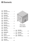
I . Configuration and Installation Dimensions of Model Y480 Diesl Engine
co
C")
&
,pl
N
&
C")
&.
j
'5
51
-0
C")
&.
Cer.dine of preMUft! 141.3
relief IevH hole
I
187
478
46i.5
!xhauatouUet~~... 1--
200
.1
View A (cyl_ _ block)
:1.1
~! _I ~~2lIiM3'~ I" il i
II
II
~
o..i
¥
I
!
1:::1
o
;;
4J
View B(cyliPder block}
~
37$
Supply
ban.
ConnediAI........,ofO,.. .... itabouli.
6820S
.362HB( ,..- )
Il«.'OI'didl to aaIIOmer'.
requeflL The dilllanCe
.between &bt: outer ~Ml
/,'
.'
.'
.'18
lattaI..- dimeMio1\4Jol ~ ...... foot
:;~
,
~of_~m
~.290
UUIIoilhe Oywheel it
!
Craakahaft cenCeru.e
/DiIbeAllioDs e~ outlet
••
1«b2~
8
6-MI
4-.17
'74
325
n.
~oI~ft.lnIe1t'~~
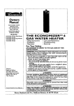
Configuration and Installation Dimensions of Model Y380 Diesl Engine
Me
(N..m)
104
Me
_l.-
96
V
V
V
~
~
r--....... ~
~
~
r---.... ~
88
~
..
He
(kw)
Ne
V
~
20
16
~
~
r-.......
V
~
/"
~
-----
~
.......
---- ------
~
~
~
ge
(glkw.h) .
,
y'
ge
~
r---.....
_l-..--- ~
~
l/
255
245
-.
235
I
I.
I '
I .
I
,
1600 1700 1800 1900 2000 2100 2200 2300 2400 2500 2600 2700 2880
m
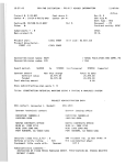
Pertonnance Curves· of Model YD480 Diesel· Enging
m
SECTION 1. DIESEL ENGINE SPECIFICATIONS AND
TECHNICAL DATA
I.Specifications of Diesel En£ines(see Table 1)
Table 1
Model
i
Y380 __. :
--.. -----...-.-.... - - - - -...---.---i-..-----.------...--....
Y380T
: Y480
: Y480G---1..--·-----·-···-----·--·-1-----·------·--···..
: YD480
YSAD380·YS380
YS480
YSA480
YS.A480
...-....-- .....-.-....--.--.--.. --.-.-- ....-- .... ----....-._-_ ... --..._-.- ...--....
--_.---_ . .,....._._
Vertical,\vater-cooling,foUr stroke,direct iqjection,dry liner .
i
Vertical,\vater-cooling,four stroke,direct injection ,wet liner
.J....
Type
I
i
~
.
_'__ _ ____:__ _._. __.
.___L_ _.
i
. _ .__
.
C~mb~tion Ch~ber T~-r------- ·---·-·---.,V~e~--~~b;------·--···--·----- ---_·_---Di;~t~j;t-i~;- - - - - - . - - . - -..- - - - - - ---.---t--
-..--.-.-- --------..-.--
Nwnber ofcylinders:
..-
-.--_.-.-
---------.~.----.--_._
3
__
_
..i-._ _
.-----~.----
_.._
4
---. ----.-- . --.. -------.---.·..--V~rt~~·~h~be;··--···· . --'-'"
- - - -.. --.--.--
:
3
4
_ ~_ -;:~~~f~~--~~~- =--: -~~:-~~-~~~-~~-~~==-=--~==~~---=---~ =-=~ --~~~~---~--i5~~_ ~-------Compression ratio
1
22.5
I
--TotaI~~~L)-T--------l~357----~--i
18:
,---1.35-"- --
--------1:809
----- ---------.--------+-.-.-----------.----.--.--.-------1----.------..----.---.. _.. --_ _..-
Firing order
....
I
1-3-2!
I
----.--. - - - - - ·-t-------·----- -.-.---..--~.--.--_____t_----.-:-.~-.----.---
__ Rated po~et{kW)
.-t__.. ~ ~~=:30.?
.__L
Ratedspee«r/min)
I
2200--3000
---.-------~-----~--.-- .....-.------. ------ -----.---- .--- ..
Max.torque(N.rn)
- - . - - -..- - - . - - - - - - - - ..-
i
..
-
---~----.----_:-.-.--.-._---
..
-l_.
.
:__
1-3-4-2
~
.
_..
.,..
22.5
1.709
i
1.809
--------t-----.------..-.--- _-
--.-_ -.._-.:. ----
.-.. -., - ------ .
. !
1-3-2
i
1-3-4-2
-:.-----------·-·-r------· .---. '-';" . ---- ..... -..-----t------..----,.--------- '" - ._--..--: --- -- --.. --- ------~-.!~--..:-~?~~J--l-0~~~-- ..~ !~:'.~~:~_._ . L_. !.~--~~ _ 1__0_--_.__2__8_._5._~. 10'"-29
I
2200--3200
I
2200--2800
2200"-'3200
......J
.
---.----.----------------- .. --.. -
---.-.-.--.-- - - - . -
~272
---r--
i
....
...------...-.------...
. -. _.- ...__ . .
~43.4
.
....
.1...._ ..
1.282
90
.. -.-..--.---..
~_~'"-_29
-~-------.--
Min.s:~c:lco;rn. _+---.
i ~274.7 I ~278.8 i
._--_-...
~
_______~~~
-
.'_
- - - , - - - - -..- - - -
~272
247
:-_.
...
...
.....
~270
~269.3
-~~-10~~~~~±1~~--lUfU~:~-~~~~~~~~~~~k~.
(before TDC)(JI(rpm)!
l.I8±1126OO, 16±112400, 15±112200
16± 112600, 15± 1/2400, 14± 1/2200
-------.. ---··--t-..·-.. ·----··--------·-·---··--··--------- - ---- -----.
---.-c:----
---.t-- ----.------ ---------- ..- _-. --1---·'---'·'
18±ln800.
16± 1/2600, 15± 1/2400, 14± 1/2200
---------.-
-.D-~In-:-.~-~~-~-t-------~--13.~:!=-~~-------_--l--~:~kw~:--;
. ...----__r.otafio..n.~~_ftywiteel) +..
Cooling
method
I
.-----.----.--------1-----. - Starting method
!
__
_.__.__.
.---~--
_.-
.
._..
.
. _.
---.-------- --_ . ---.- -.----. -- _- .-.----.------.-----
""
-.- ---.---._
587X494X61O
687 X 494 >< 610
-----.-------
. __. .__~. .
._. _.
. ._"
_.. _
Forced. water
Cooling
----- . -. -_.-_ . -.Electric
~
----.• -- ._.._.-_..-
1~.2:i:0.:~
-~~~-: ~=~~~~~~~~~-=~=~~~~=~~~=~~=l_-~~~
~t~m:)S
,
XX
' 687x494X623 : 587X494X623 • 591.5 494 566 ,
1~
676.5X494X608
l~
i
587 x494 X623
..-1
II .Specification of Main Accessories(see Table 2)
Table 2
Specification
Designation
Nil
YS480 YS~~~.; Y380
'YS380
Y380T
Y48OG; Y480
Fuel injection
Governor
-_.--_.
pump
_..~!l1.~g~! .. ~iamel~(~!!l) .-
.' ...
~--_.-
2
Fuel injector
,
7.5 . . 7., 6.5
S~_gl.~~~~ti!l8.P~!~I1_o/~.
P21
• __ ••' _ '
....
--_!~_ _..__.__ .
._. S~~~r!.~.j~2 __._._..__
3
Lube pump
PF68509
___._.... __ ~i~g!~__~!~~pi!1~~~:~p~~~~4.~1_._ ..
-..-- ._
-+
._.__.__.__ .
.
Four holes t1> 0.23
19.6+0
Rotor
1300
1300
150r18
18
_ _ "'_'_' __ . .__ • _ _ ._.
_._ . __ ~~a~j~(I!~~~)._ ..-.
ZCK 154S423 CN-LLA 1545423
13.2±0.5
-.-...•..---.- ..'..
._.i. __..
lower inertia series s
1
-._- - ..,..•.- .
._. _._._.....__. .,__. .~.--. --!~~t.~~-p.~~~~r~~~ . __. ~___ _
'" -_
YSAD380
l.Iw or BQ pump
7
Model
Nozzle
set
....• -_._. -_._.__-,r--DiaQleter
of
nozzle
hole(mm)
_. .-_
- - ._"-'.' ----.-.--...•--....• ·······r • _ _ •._•• _ •. _0. __ •. w ••
,._~_._.
YD480
. ~~I~~~~~J!!~~~~j~~~.c~~_t.t"if~g~.1
~
!_~~~ ~~.~iye!Y~_!!~_
__ ,_ .• ,
YSIA480
IW or BQ pump
I or BQ pump
._.
._.__..
._.
"... _. .r!~~!.~_~~p~) .-----_.... _----~~_._.-
......
NI
4
Water pump
Speed(r/min)
.
3000
~~.• _~_-~~~C;P;~~~~!~) __-:_ .~.~: ..-~.=~.~-~_~.=-~--_~~_~=~~.:~ =-~. '.- ~-:!~
--r - . - -~!~t'!'l.-.-- ..-.
._._. __ _ _.. _ _._.. .
5
. _ . _..
_._. . ~~!i~~Q~ . J!l2t.~.
, Model
Starting motor
____.
~--_
Dynamo
1_
~._._._
•.
..
yol~.B~.lY) ....._...
QD1315A" D138Y
..
i·
P_o_w.e~il£..w)
.__
12
1.80r2.5
_-._-_ __.._!~_ .._ - -.. ~~~.C!!.
••
-_
QD1322",,_.. --QD1315.l\"
QD138C
_ _._--..D138Y"
_-_. __ ._._- _----- ""-"'-"--."-~
.__
160
8
~_ .. _---. __ ._-_._-~_.
5
4000
. . __.. _'.. ._._._ . . . _ .
'-"7-'--"'-"-
----
--.--.--.---.-
2.5
., __~~!~~!!-.~.~.!!Y_~B~~~~n!
--
.~a.!!'-~ ...
JFll
••• __
Power(W)
350
_._-_. __
Voltage(V)..
_._ _- _ _-.- ,._....•
-......-_.
Fuel filter
-.~.--
....
..._. __.__..
......
...
..-- ..
_~
14
---
. __
_.Iy~.
_ _.- ----_. ~~~_._.. ..
... _-,- ... ....
__
Type
--,.
.. _--
Lube oil filter
9
Air filter
Electrothennic
plug
._~ _-_....- '---"'---" _
.....
...
...•...•
C0506A
--
Single stage,paper element
------~
Model
J0708orJ0810
J0810H
~.~~~~~~e'.p!,~r element
K1317A
:_ _ _ __ _ Ty.~_..__ .
_.~_.
10
_
....... ....
..~IDg!~. ~!@g~.2J'-8~r ~J~~1!t .,.
.
--_ - Model
_- - _
... _. -- -II~ . _
..
.....
•.
...
~._
Model
-
Shrouded
--_.. ,,- - ..
*-~._--._~
10-12-65
.-
No accessory
ill.Main technical Data of Diesel Enldne
1~VaJve lash(mrn)
O~25
Intake valve(coJd)
0.20-'-
Exhaust valve(cold)
0.25-·,' 0.30
2. sinkage ofvaJve(mr~)
O.7~'
0.9
3.Torquefimits ofnlain bolts and nuts(N • "1)
CyI;indefhe.ad boits
150""-' 170 (Y380, Y380T, Y480G, Y480,
YSv;\480~ YS480"
lT~}\.. 480, )'S380)
175"~"''i95
Main bearin~ cap bolts
(YD480,\ YS4A..D380)
110---·· 130
Connecting rod bolts
50'-~"
60
Flywheel. bolts
60""~
70
4.Temperatureand pressU:Te limits
(1 )Exhaust temperature(~C )
t~
620
3200rpm>n>2600rpm
t~
600
n~
t~
550
~
100
n~
3200rpJn
2600rpm
(2)Lube oil teolperature(OC ')
(3)Lube on pressure in ~fIain Passage(Mpa)
At norrnal operat;on
0.2"" 0.4
~
At nlin. Steady Speed
0.05
5.Govemor Characteri.stics
Mift. idling ste~dY~Speed
.~
900rt.,-m -'
'1',;<
Steady regulation
5 ~/o
-- 10 ~~t;
1.,·3
IV .Fit Clearance and Wear Limit of MaiJl Parts(see '"fable 3)
Table 3
2
Assenbly limit
Wear limit
(~)
(D;lm)-
Connecting rod'j6umal and connecting rod btishin'g
O.()40"0.089
0.20
Piston pin and1c~nnectingxod sm,\U end.bushing .
0.025-0.046
0.10
06-0.160
0.40
I .._-- -+-_
3
----.-- -..--- .-- -_._-
--
---
-..---- --.. _
_.-
-----
.
skirt and cylinder liner
4
Side clearance between the Ist ring and its groovt:
0.060-0.092
0.20
5
Side clt~arance between the 2nd ring its groove
0.040-0.072
0.18
1.60
7
8
9
of the 2nd ring and
(~rankshaft "mainjoamai
on scraper ring
0.250-0.400
2.20
and main 'bearing
0.070-0.139
O~25
10 Camshaft'journ~J' al~d bushing
-
_. --'"
O.050..0.1()O
__
- .• - _- •.-. -_
~,
_: _
LJ I f Idlegenr shaft journal and bushing
12 Intake valve stern and valve guide
~
----_., •.- .., " - ~.~,..•~. - -_.--
~_
-'-- _ _ •.•-_.- .- ._---1..-------.---., ._
I 0.025...0.'075
i
i
I
0.18
.__.__,..... ._.J_?·i~.;~O~~~~-T'~_~~~i~-=~
!
0.040~0.077
!
_.._._-- ---j"-_ _._ -_. -- ·-·
i
13 11xhaustvaive stem and valve guide
14 Rocker arm shaft and bushing
_._. ·-1
_
i
i
;
-1--
0.15
_--._..-- '''-''''
; 0.016-0.061,
0*20
_____.:..__. . __ .;.:_._. . . _.._~ __ . ~ __...__.. __ _...__ ...
L .
:
I
-e
-
.
i
15 !,Axial (~Jearanueofcrankshatl
OJ)75-0.265
1
I
. --- ----I
a_n_c_.,t~_(_)f_c.,a_n1
... ...s....
h_aft_
•.
-...-1.....
6_A_x_·ia_l_c_l..e_·,a_..
-.-.....-""----'--'.~-_...J.. 1_°_0°_5_°_-°_,2_,2_°_.. .,
1-4
1
SECTION2. OPERATION
I . Fuel Oil ,Lube Oil and Cooline Water
I.Fueloil
Users can select the proper grade of fuel oil
the
~eneral
fuel.Use
area in. China,the
~de
fuel.Before
Ji~ht
"0"
bein~
~de
accrdin~
to .the local ambient temperature. In
of fuel oil is according to the standard GB252 light diesel
diesel fuel in summer, while in winter, use grade "- 10"
filled into the
en~ine
fuel tank,the diesel fuel must be settled for a
li~ht
diesel
lon~
period
(normally' at least 48 h).Then draw out the upper part.The fuel should be filterd by silk cloth
while
fillin~
it into the en12;ine fuel tankJt will extend service life of injectors and injection
pumps by usin~ the wen settle diesel fuel.
2.Lube oil
In the ~eneral area in China.,users can select the .proper ~rade accordin~ to GB/T11122
Lube Oil of Diesel
lube oil.When
En~ine.Use
bein~ filled
JUade CD40 lube oil in summer,while in winter use
~de
CD30
into the en~ine oil tank,the oil should be filter~d by screen.
3.Coolin~ water
It is recommended to use soft water such as rain water,city tap water,or ciean river water for
en~ine coolin~. We))
containin~
water or tap water from well water could not be used.
too Inuch minerals will form. water scali in an
en~ine
Coolin~
water
cooling system,affecting the
\.
engine cooling efficiency and
givin~
rise to engine troubles.
Hard water(wel"l or spring water,etc.) should be softened before being used.There are two
.softenin~ methods;
(I )Boi lin~ up the hard water;
(2)Addin~ 20~
caustic soda (sodium hydroxide) to each 30L hard water to make up a
solution.
When the
en~ine
operates in cold weather where the cooling water is liable to freeze,anti -
freezer can be added to the cooling water to prevent it from
freezin~.
Glycol or alcohol aqueous
solution is most ordinary.
If it is difficult to start the
en~ine
under lower ambient temperature, heat the water to about
80 e before fining it into the cooling system.
G
2-1
IT .Preparation before S*ar1ia2
I.Check the·tifdltness and reliability of aU connecting parts. Check control levers (speed
control lever and
stoppin~ lever)
to see whether they can be moved· freely.
2.Rotate the· crankshaft several turns,be sure that all movin~ parts move freely.
3.Check the oil level in the oil sump and injection. pump to see whether it is kept within two
marks on the dipsticks.Make .sure that the fuel tank has sufficient fuel and that the fuel pipelines
are unblocked'.
4.0pen· the fuel tank cock..Checkwhether there is. air in·the fuel system. If necessary,loosen
the vent screws on the fuel filter and· injection pump,operate the
primin~" pump
on the fuel
delivery pump by hand until the fuel flows out Qfthese screws without bubbles,and retighten the
vent screws.After that,loosen the union nuts of injection pipes on the iQiectors
cankshaft to bleed, air from injection pipes,then
reti~hten the
an~
rotate the
union nuts.Check all fittings of the
fuel system to se,e whether there is any leakage at all joints.
5.Check the radiator to see whether it is filled fully With water and whether there is any
leakage at all ioints.
6.Che·ck the. accessories to see whetber they arefinnly and, reliably connected.Check the
. electrical system: to see whether the battery is fully
char~ed,alJ
wirings are correct and all
connections are ti~tened.
7.Check the clutch to see vvhether it has disengaged.
ill. StartiR2
I.Set the speed control lever at the middle speed position.
2.Turn the ignition switch to
"preheating~' position
to heat the electrothermic plug for 20 . . ~
30s.
3.Turn the ignition switch to "on" position.Press the starting button to start the engine.If it
fails to· start,reJease the button immediately. Wait 2tninutes 3 minutes,before starting the engine
again.lfthe engine fails to start after 3 attempts,check the cause and remedy the fault.
4.As soon as the engine has been started.,release the press button immediately.T'hen tum the
ignition switch to another position to charge the battery. At the sanle titne move the fuel control
lever until the engine runs at idling speed.Check the operation condition of the engine to see
\vhether there is any abnormal' noiseeEspcciaHy pay close attention to the readings of oil pressure
gauge, which should be within specified pressure limits.Then wann the engine up with engine
speed' ~aduaHy increasing to
1800~-'.J
2000r/m'in
2-2.
IV • Operatioe
1.00 not load the en~ine until the cooling \\'ater tempemture is over 50°C arid the lube oil
temperature is over 40 °C . The
en~ine
should not be operated undrer rated operated under rated
output before the outlet water temperature reaches approximately sqoc
.
2.Increase or d~crase the engine load and speed gradually andevenly.In normal case!do not
load and.unload,the
en~ine suddenly.
3.During operation,observe the gauges on the instrument panel
readin~s should
frequentlywher~
the
be within the specified limits.Pay close attention to the exbaustgas color and the
operatin~"noise.Ifthere
is any Jault,stop the
engin~ and inspect it.
v·. Stoppine
I.Before stopping,take off the load ·and reduce the engine speed gradually.Let it run at
idlin~
speed for a few minutes.Do not stop engine until the outlet water tetnperature falls to
belo\v 70°C.
2.After stopping the engine.. the ignition switch should be turned to the middle position.
3.In winter.,when ambient temperature falls to bello\v 5 °C ,aftertheen~~ine' stops and the
cooling water temperature falls to below 60
e
0
,open aU drain cocks on "the .cylinder block. and
ra.diator to drain otl:' all \vater remnant within the cooling system,in order to avoid damages of
parts due to freezing.If anti -
freezer is added to the cooling water,it is not necessary to drain
off.
2-3
SECTION3. MAINTENANCE
For reliable engine operation with Jess wear and longer service Jife,all maintenance work
nlust be carried out as foJlo\vs.
I . Routine l\taintenance
] .Check the oil level in the oil sump and it should be between
t\VO
marks on the dipstick
and ncar the upper one.For a new enfl;ine or the engine reused after stoppin~ for. a long period,the
lube oillnust be 11.IJed to the upper
mar~and
op,erate the engine at lower speed for 5
"--.J
1Onlin,
then stop the en~ine and measure the 'Iube oi I level oncea~ain.
2.Check the cooling \vater level in the radiator.
3.Check the lube oil level in the governor of the injection pump,replenish the oil to the
specified level ifneeded.
4.Eliminate oil.. water and gas )eakags of the engine.
S.Check ti~htness and correctness ofaJI conlponents attached to the engine.
6.Check tightness and reliability
ofen~ine
foundation 'bolts 'and the connection between the
engine and the dirven ·machinery.
7.Keep the engine clean.Oil,\vater and dust gathered on the engine surface should be wiped
away with a dry rag or cloth dipped in gasolinc.Especial1y keep the electric equipment clean and ·
dry and clean out the dust on the fins of the radiator.
8.For the new engine.. after SOh tr.ial running,renew the lube oil in the oil sump,fuel injection
pump and
govemor~and flush
the oil filter eJement..oil sump and oil strainer.
9.Promptly eliminate the troubles and faults found.·
II . Maintenance after Every 100 Accumulated Qperatine: Hours
Besides the
n
routine maintenance" work,and the
fol1owin~ items:
1.Rene"w the oil in the sump.
2.Clean the oil filter or ,renew the paper element if necessary.
3.Clean the fuel filter or renew the paper element if necessary.(lt may as \vell be replaced
after every 200 accumulated· operating hours.)
4.CJean the oil filter or rene\\! the papereJementifnecessary.
5.Clean the va.lve lashes..read just them according to the recommended procedure jf
necessary.
3-1
6.Check the tension of the fan beh,and readjust it if necessary.
7.FiJl the nipple of cooling water 'pump bearing with ZG- 4 calciumbased grease with a
grease gun.
8.Clean out the dust in intake manifold,clean the inside of the aircleaner.. brush off the dust
gathered on the 'paper element surface,and clean the inside of the exhaust manifold and silencer.
9.After every 200 accumulated operating hours,check the injection pressure and spray
pattern of injection.If necessary,dismantle the iniector"clean the nozzle set,and readjust the
injection pressure.
IO.Check the voltage of battery and the specific gravity of battery acid,which should be
~'ithjn
1.27/"---'
1.2~(at
ambient temperature of 20°C ).W'hen it is less than I. 14,the battery should
be recharged.The .Ievel of battery acid should be J 0"-' ISmm above
th~
pole plate.lf insufficierlt,
add distilled water to the required level.
1I.AII' parts dismantled tor maintenance should be ,washed.,and cleaned and correctly
reassembled.After reassembly,start the engine and check \vhether it is in proper operation"AlJ
faults should be renledied.
ill .Maintenance after Every 500 Accumulated Operatine
Resides the work of Inaintenance atter every 100 accumulated operating hours,the
following items are needed:
1~Check the injection pressure and spray ·pattern of the injector.If necessary,dismantle the
injector.,c·lean the nozzle set and readjust the injection pressure.
2~Check
fuel delivery of the injection pump,and recalibrate it ona test bench if possible.
Check the injection timing,and readjust it ifnecessary.
3.Check the sealing of the intake and exhaust valves.If necesary,grind and lap the valve
seats and reaQiust the valve lashes.
4.Check the tightness of the connecting ?a rod,mian bearing cap and tlywheelboJts.
5.Retighten the cylinder head bolts and adjust the valve lashes according to directions given
in section 4.
6.Clcan or replace the paper elelnent of air cleaner.
7.Clean the cooling system.The cleaning solution can be prepared by adding 150 graIns of
caustic soda(NaOH) to every litre of \vater.Before
cleaning~drain the
system completely and then
till in the saine capacity 'with cleanIng solution. Let it remain in the systeln for 8"',-.1 ] 2h:rhen start
the engine and run it until the temperdture of cleaning solution reaches nonnal operating
telnperature.Stop the engine and drain the system immediately in order to avoid settling of scale
\vithin the system.Finally..flush the system with clean water until all sediment is flushed out.
3-2
,8~Check
whether the thermostat is in
~ood .order.Examine ·.the .waterdropp.i~out
from a
weep hole of the -water pump.It is necessary to renew the water seal,if tlowinll;out too much of
water.
9.Check the
firm~ly and
wirin~
contacts of.the electric equipment-to see whether. they :are connected
welLBurnt marks should be removed.
10.Afterevery 1,000 accumulatedoperatin~hours,add the' following items;
(I)Make an overall check on all' pam and components.Make necessary .adjustments and
repairs.
{2)Dismantle the dynam'o and
refull them -with clean
startin~ motor.Clean
out tile dirty
~ase··i.n
the
bearin~
and
~rease.rhec·kthepinion ofstartin~ motor.
II.After every :J ,500 accunulated
opera1jn~ hours,add
the followioll; items:
(1 )Remove the cylinder head,check the valve and valve seats and other parts of ;cylinder
head asselnbly.
(2)Remove .the carbon de,posits 6n the surfaces of cylinder head,Hner,piston and piston ring,
etc,and wash ,down them.
(3)Check and measure -wear of the pistons and piston rings.
(4)Check and measure wearofthe,cylinder:lUler.
('5)Checkand measure wear of the crankshaft main joumalsandcrank .pins£lean :htbe oil
passa~es of the
crankshaft.
(6)Check wear 'of the 'main 'bearin~ and connecting-rod bearing shells.
(7)C·lean,oil "passages of the cyJinderblockand replace -lube oil
:W .Preservatioo and.Steraaeof,Enaine
'If the -engine is to be put out of service for a comparatively long period of time,it is
necessary to .preserve it according to the
1ollowin~ procedure:
I.After the ,engine 'steps and st.ill does not coal yet,drain out completely the ],ubeaiJ.,cold
water·and fuel immediate'ly.Clean the oil sump and oil strainer.
2.Clear out the dust andoi:Jon the engine surface.With ,antirust oil smearal'l the UDflIlinted
ex'posed surfa.ces 'ofengine e)(cept rubber and .plasticparts.
3 Jieat :the fiJ.tel:ed ,lube oil to 110r-.., ~120 °C ,unti·) all J!lubbles in the surface oGf·.oil .wsappear.
"fhen pour the dehydrated -,oilinta ·tl:le oil sunp unti·loillev.el :reaches the upper mark, and turn the
engine,in order to ,make s'urelhat the lube system is completely filled up with this oiL
3-3
~;'4:Poursome;'~dehydratedbil
,into' cylinder
throu~h iniector'"~
assembled holes"
Of}
the
cylindef:heaa,sndtumfhe'crank..4;haft to make sure that the piston,piston rinR,cyJinder liner lind
valve seat are all covered \vith a layer of this oil.
,,'5'~Block'theoutletsof intake
and exhaust manifolds (silencer)with.wooden plugs Of\Vrap up
properly with plastic film in order to prevent any dust froln getting in.
6.~rhe
engine shouldbe:stored in a clean' room with goodventiJationandJow humidity,The
erit-iine- sh<)ulElbe covered.Chemicals near it'are strictly 'prohibited.
The preservation according to the above procedure may be vaJid tor 3
perl 00,fe))eattheprocooute. .
3-4
nlonths~Over
this
SECTION.4 ENG'INE ADJUSTMENT
I . Ad.iustment of Valve Lash
When .the en~ine is nlaintained and repaired,it is necessary ·to check and, adi~st the valve
lashes.The recommended Jnethod of a4iusting the
valve system and valve lash is as follows:
I.Remove the, cylinder head cover.Check and
tighten the nuts fastening the rocker arm shaft
stands.
2.Tum the crankshaft to make sure that the
piston of 1st cylinder is at the compression. TOe
position.The timing mark on the inspection window
of the fly\vheel housing exactly points to the "
1l1ark
~n
the flywheel rim ,or the"
c.rankshaft puJleyis
ali~ed
0"
0'"
mark on the
\\,ith the pointer on the
cover oftHning gear housing.
3. slip a feeler gauge bet\;veen the rocker arnl
and the tip of the intake or. exhaust valve stems of
the 1st cylinder
respectiv\;~ly to
valve lashes.fntake -valve lash'
Fig. 1 Adjustment of valve lashes
check and adjust the
and exhaust valve
lash in cold nlust be the value specified in section I.Then after turning the crankshaft by 18()'J
to adjust the valve lash of other cytinders a(,:cording to the engine firing order( 1-' 3- 4-2)for the
tour cylinder engine arid'l-3-2 for three cylinder engine.
II. Adjustment of lo"iection Timing
'ro ohtain the most econolnical specific filet consumption and to chsure normal operation of
the enginc,injection titnin.g should be adjusted properly.For the Model 485 diesel
angle at \vhichinjection
be~ins should
en~jncs,the
be the value specified in se'ctionl .
The adjusting method of injection timing is as
I. Vent the air trapped in the fuel
follo~'s:
system~and
turn·the crankshaft 'to fill up the" ini"ection
pump wtih fuel.£)isconnect the injection pipe of the 1st
cyljnder~turn'thecranksh3.ft
slowly in the
direction of its rotation and at the saIne time observe the fuel 'level in the hole of fuel
When this fuel level lust starts to rise,stoptum the cranksha1t itnmediately.
4-1
pipeunion~
2.Check the· timin~ mark on the inspection window of flywheel housing to see. whether it
aligns with, the. correct gradulated mark of specified, advanced in.iection
an~le
on. the flywheel rim
(or ontbe crankshaft pulley).
, 3.In case· that tbey do not match with each other,the
adjusted by re.movinfl;' off the front cover on the timing
screws fastening
thei~iection·. pump
timing
~ear
advaneed~
~ear housjn~
support(.,See
fi~.2).If
injection an~le can be
and
loosenjn~ the
three
timin~'
is too
the injection
advanced,tum .the timing ~ear support anticlockwise to' the 'proper angJe.Otherwise,turn the
clockwise.lfa<liustin~ range
support
is not enough
due to litnitation of the three elongated holes, loosen a
little the three fastening, nuts on the triangular flange
of the
inJection~'pumJ) and:
Facin~
the· front end' of
tum the injection ptl1np.
en~s,when
i~icctif)n
pump rotates clockwise,the' fuel
""hile
the'
pump
the injection.
t:etard~;
win·
rotates' anticlockwise,the'
fuel
injection wi.ll' advance~
4.Additionally,if the engine has injection an'gle
advan~edevice,the
adjusted' by
triangular
advanced 'injection angle can be
loosening the three nuts on·
flan~e
the
of injection pump and turn the
injection pump shaft.Facing the front end' ef'engines,
when the injection pump rotates clockwise,the fuel
injection
will
retard;while
the
pump,
rotates,
Fig. 2 AdJlIIInleIIt of spedIIed
adv~ bijection
ugIe
anticlockwise,the fuel injection will advance.After
tum the injection pump once.. it is must to tighten the three nuts and check the advance injection
anRle a~ain uotin the 'ldvance injection
an~le
fits the spcified value.
ill. Ad.iustrnent of In.iector
Injector test and adjustment must be performed on a injector tester in order to adjust
injectin~, pressure,inspect sprat)~
Too Ili~ or
roo'
pattenl and remedy faults.
lewer injectol' in.,jectinJ{ pressure,and abnoflooJ spray on damaged injector
partswiU cause e~ine traubles,such as, Mack snl0kin~·,power ans' speed; drollPlng~incr~asing
exhaust ternperature and diesel' knocking,etc.Generally--the "shut off" method is recommended to
4-2'
check a fauly injector,i.e.loosen the nuts of injection pipe .from the injector of every cylinder
sl1ccessivelY,and observe the exhaust smoke.When the cylinder with the faulty iniector stops
firin~black smoke
would disappear.and
en~ine
speed is not appreciably affected or not affected
at al1.1t may also be checked by IisteninJ]; to the chattering action of the injector of every cylinder
with the flywheel rotatingJf the distinct clear sharp sound of certain cylinder could· not be heard,
the injector in this cylinder may be faulty.
I.Procedure of injector testing and adj ustment
(1 )Work the injector tester hand pump until the gauge pressure reaches about specified
injection pressure. Then operate the hand pump slowly and adjust the injection pressure
at
which injection begins.The nozzle should not show any signs of leaka~e. If fuel drips around the
nozzle tip after several tests,the nozzle set must be dismantled for cleaning and winding.Then
test it again.
(2)Relnove. the lock
nut~turn
the adjusting screw to get the pressure at the beginning of
injection \vhich should be specified value in section I.Then tighten the lock nut,and test it again.
(3)Work the hand pump at a rate of approximately 1 stroke per second and observe the
nozzle spray.The fuel spray should be even,and well atomized in a shape of cone.At any
cros~
section of the cone.. the atomized fuel should be finely and evenly distributed.Fuel droplets and
irregular pattern
wh~ch
can be seen by naked eyes should not be present in the spray. There
should be a distinct clear sharp sound at the end of iniection.Generally,irregular pattern of the
spray is caused by needle valve seizure,fuel dripping is generated by damaged conical sealing
surface of needle valve and spray split results froln carbon deposits on the tip of nozzle and its
heat deformation.
2.1niector dismantlement and repair
( I)Before dismantling the injector.clean off the dirt gathered on it .Clamp the nozzle body
in a vice lined by copper sheets on its jaw \vith the nozzle upward.I'um off the 'nozzle cap nut
and take out the nozzle set.Draw out the needle valve from the nozzle body and soak it in clean
fuel oil.Then clamp the injector in the vice upside down again.Dismantle the adjusting nut,and
adjusting scrc\v,then take out the injector spring and spindle.
(2)
If the nozzle set is seized or clnits fuel badly,it Inust be cleaned.Soak the seized nozzle
in the) oil for a \vhile.and clamp the needle valve by a pliers \vith cloth Ii ned. Then rota.te and
dra\v it out slowly.iust to avoid
body with wooden
(~hip
scratchin~
its surface.Decarbonize the needle valve and nozzle
soaked in fuel oil.lt is forbidden to clean theln ,"'ith InetaI chip. If the
4-3
guiding surface ofthe needle vaJveand nozzle. body is not smooth enougp,it may. be lapped. \\lith
a.littlebitofclean fuel o it, th.e n clean off any metaL particulates in clean. fue.l.While
needle valve with n(}ZZlebqdY,l1ever knock the needle valve
~ainst
lappj~
of
the body.
IV • Ad.iustmentofLube Oil· Pressure
See fig.3.Lossen the lock nut and turn the adjusting screw with a wrench to take the lube oil
pressure within 200 ~-
400kPa(in cold state,. the pressure maybe bigh~r slightly). After
adjustment.the pressure adjusting screw must be-locked ·by the lock nut.·
v .-Ad.iustment of.ln.iectio·n Pump
The -injection pump has tested and calibrated at
the'
factory.lf
it
is
necessary
to
read iust,the
readjustment must be perfonned in a injection pump
test bench with ·astandard· injector and injection. pipes
of standard
len~haccording
to the instructions in
Operation M.anual of the Injection Pump.
I
VI ·.Adiustment of Decompression Arm Lash
Fig. 3 Adjustment of lube oil pressore
Turn the crankshaft to make that the piston of 1st
cylinder is at the conlpressionT.D.C:. position.'I'unl the decolnpression arm to decompression
position.IJoosen the lock nut.Turn the adjusting screw to bring just into contact with the lock arm
of intake valve (Le.no valve lash).Screw the adjusting screw by 3/5---4/5 turns
intake valve lifting to
O.6~
a~ain
(nlake the
O.8Inm).Then tighten the lock nut.After this.. according to Item 3 of"
Adjustment of Valve Lash",
make the piston of another cylinders at the compression TDC
position one by one and adjust by' the same method.
4-4
SECTION 5. CONSTRUCTION OF DIESEL ENGINE
I . Cvlinder Head
When assembling'lcylinder head··is fixed on the cylinder block with cylinder head-bolts.A
. torsion spanner should be used· during tightening the bolts.The bolts are tightened several times
in sequence shown in Fig.4 until they reach the specified torque limit.After dismantlin~ and
assetnbling
the
cylinder
head.itis necessary to shut
down the engine when first
wanning up period is over.
Retighten each bolt on the
cylinder head according to
the specified value of torque
.....e-+
limit and readjust the valve
lashes.
Fig. 4 Tightening sequence of cylinder 'head. bolts
The intake and exhaust
valves are made of different materials. Each couple of the valve and valve seat should be ground
in' order to prevent leaka~e.
It is' necessary to grind \\-'hen gas leaks out due to burning out,lnechanical pitting and wear
appeared on the sealing fa.ce of valve and valve seat. When grinding,apply a grinding paste(fine
valve sand)on the conic sealing surface of valve.Then the valve and valve seat are lapped in pair
unit) -a even,continuous and lustreless sealing band appears.Itis strictly' forbidden that the
grinding paste enters the valve guide.After lapping,clean the valve.. valve seat and valve guide
carefully.Wearing of the valve guide nlay cause the eccentric wear of valve sealing band which
results in abnormal sealing.Pour sOlne kerosene or diesel fuel into the gas passage,and observe
\vhether there is any leakage,then check the valve sealing.
ThesealinJZband of valve and valve seat is normally 1.2.. .,1.6 mm in width.After a lonJ;!
period of service and regrinding many times,the width of valve sealing band may get
which may cause abnortnal sealing.Being kept concentrical with respect to the valve
wider~
~uide
hole,
the contact band on valve seat is to be refaced by a reamer.Then gring the valve and valve seat
in pair.
5-1
.After service for a
lon~
period -
and
many
times,
rew-inding
the sinkage will increase.
When it exceeds 2.Qrnm,
replacing the valve seat
should be considered.
Check
the
valve
frequently. The
lashes
recommended
method
is
para~raph
adjusting
shown
, .Fig. 5 Valve sinkage
on
I of Section 4.
If the lashes are too large,it may affect the corre'ctness of valve timing and the noise level of
valve device rises.On the contrary,it may cause
leaka~e·or valve
burnt out.
II . CvlinderBLock
The cylinder
bl~ck
is made of cast iron and is of crankshaft centerline of'f- split face
stnlcture. Besides the fitting bores for the liner and the cylinder head boltholes,on the top plane
of the block there are holes leading water to the cylinder head. Near the rear end of the· block
there
are
channels
delivering
lube .oil upward to the .cylinder
head.
The water pump is mounted
on
the
upper front
face
of
. ----"'p -- . .- --
cylinder block ,and the gear
system is on the lower part.The
flywheel housing is installed at
FIg. 6 Protruding height of the liner ftange plane
relative to the plane of cylinder block
the rear face of the block.On the block bottom,there are a lube oil inlet,a hole for the lube oil
pump and tap holes for instaJlinJ! the Slunp. 'There are a side cover and a breather on the left side
of the block(facing to the front end).There are the lube oil filter,fueJ filter and drain cock on the
right side of this block. The Inain lube oii line and its branches are arranged in horizon. The lube
oil passages delivering lube oil to the camshaft bushes are slant. When disJnantling and repairing
5-2
the diesel engine,tlush all lube oil passages"and be sure that they are clean and unb locked. All
passage plugs should be sealed reliably and leakproof.
·-rhe tnain bearing:~\ are of cornplete suspension- support type"Since the main bearing caps
and cylinder block are rnatched to bore.Jhe matching marks are both on the bolck and main
bearing ~aps.Misplaccnlent or inverted installation,when assembling,are prohibited.The Inain
bearing shells are made of high- tin aluminiurn-base alloy.When dismantling for cleaninR,be sure
that the upper and lower bearing shells are in right places(the upper shell \vith an oil groove).The
crankshaft thrust plates are assetnbled on the last main bearing with an upper piece and a lower
piece on each
side.l~he
thrust plates bear the axial force from the crankshaft.There are oil
channels on its
operatin~
surJacewhich should be located against the thrust planes on the crank,
and its back surface is smooth.Never locate thenl in reverse. When tightening the tnain bearing
blots~tw() bolts
on the bearing cap should he tightened several tilnes in turn.Before tIghtening the
main bearirlg cap~strjkc the crankshafttof\Vard and back\vard in order to keep the upper and
lo\ver thrust plates in th(~ sanle plane."fhen tighten the bolts until t'hey reach the sp-ecified
tightening torque. When completing the crankshaft assembly,turn it at the flywheel end by hand
to check whether it can be rnoved freely.
T'he liner is slipped into the cylinder bore vertically so that deformation of the liner may be
avoided. 'I'he liner flange plane should protrude out the top plane of cylinder block by 0.07--- 0.15
mnl to keep an excellant sealing bet\veen the cylinder liner.and cylinder head,as sho\vn in Fig6.
ill . Piston and Connectin2-rod .
The piston and connecting- rod assembly c.omprises the piston,piston
taining
rings.~connecting-rod. connecting
rin~s,piston
pin, re-
rod cap,connecting-rod bolts and connecting-rod bearing
sh.ells and bush,ctc:rhe mass difference of piston and connecting- rod assenlblies in the same
engine should be within 20g.
,£\11 of the compression rings are lnade of alloy cast iron.The outer circle surface of the first
ring is plated \vith porous chrome in order to decrease the wear between the cylinder liner and
piston ring.The second ring has a conical surface. When assembling,the surface marked with a
sign lfUp" should be keptagainst the top of piston and be careful to avoid assemblin~ in reverse.
'[he oil,.control ring is of tensioning ring type:rhe radial force of oil ring is still kept while
decreasing the elasticity due to \vear.'Thus the service life of oil ring is prolonged.
5-3
Check the ring end ,gap before
assemblinJ!. the
pi,st()~ ring.~rhe
Ineasuri~g this
gap is .reconlmended as
follows:Press .down the
method,
piston ring
evenly into the cylinder Jinerby 15--20mm
ft:Q~the top surfa~e of liner.
Measure the clearance with a feeler
gauge.In
nonnal- case,the
2
meas;urin~
Fil. 7 Meuurement of piston ring end gap
1. Tbldmess leeler(puge) 2. Piston
ring
3. CyUnder IiDer
value should be O.2·--0.4mln(Fig.7).ln
case the gap value is less . enlarge it by
a fi.le.lf it, is excess.,repJace it \vith
another one.ln addition.,ineasurement should be made with a feeler(gauge)to check the side
clearance between the ·piston ring and
r~ng
groove.The side clearance for the
first ring should be
O.07~O.1 02mm
and
o.
05.--..0.082mm for the second ring as
shown in FiRS.
When dismantling and asselnbling
the piston ring,a special tool may be lIsed.
The ring end gap of piston rings should
be set off with each other by J 20 ljC to
Fig. 8 Measurement of slde surface
gap of piston ring
prevent being in line with the piston pin
seat hole.
If the piston rin1~ is seized and could not nlove when 'checking,soak it in diesel fuel(kerosine
or gasoline)for 24h or more.Then knock the piston ring slightly to
~ake
it become flexible of
itselt:On getting out the piston ring.,clean it in diesel fuel or carbon tetTal~hloridec
Check the piston to see whether there is any cracks or scars.Change the defective piston and
rene\v itsrin~s.
The cross section of the connecting- rod is 1- shaped"with the'splitting surface of large end
being perPendicular to the center line of connecting- rod.Boring the connecting- rod hole and
connecting-rod cap must be mated. Therefore \vhen asselnbling"pay close attention to the matin~
5-4
nlarks on both the connecting- rod and {;onnecting- rod cap in order to avoid .naking Qlistakes.
'fhe connecting- rod bearing shell is Inade of steel \vith high tin aluminium alloy.When the
cJ\~ar3nce between the connecting- rod bushes and crankshaft ;oumal exceeds the specified value
after
wear'n~~
or severe stripping and burning occur on their surfaces,they must be renewed in
pair.
,
r)urin.g
(~ngine overhaul or
,
rene\ving the connecting-rod,check the axis parallelism of the
connecting-rod smal! end to the large end.,which is specified to be within O.Otmm/lOOmm(both
in vertical and horizontal direction).If it goes beyond the scope.,alignment should be made.
Before dismantling the piston and connecting-rod asselnbly in cylinder ·Iiner or assetpbling,
it is necessary to scrape and clean the carbon deposit and greasy dirt on the top part of cylinder
liner.Before assembling.,smear some clean oil on the cylinder liner bore,external surface of
piston and piston rings"connecting- rod bearing shells and crankshaft jounlal. Then place the
piston guide sleeve in the cylinder liner,tit the piston and connecting...rod assembly into the
cylinder line'r carefullY,and tighten in turn the connecting-rod bolts according to the specified
tightening torque Unlit in several separate times.A"fter finishing the assembly..turn the c·rankshaft..
be Sllre that it rotates smoothly.
IV·. Crankshaftand Flywheel
'rhe crankshaft timing gear and pulley are fitted on the front output end of crankshaft.,
Positioned by the locating pin,the flywheel is fitted on the rear end tlange of the crankshaft with
six bolts tightened according to the specified torque value.A bearing· E60203 . which supports the
transmission shaft of gear· box,is fitted on the flange center at the rear end of the crankshaft.An
angular calibrating line is marked on the crankshaft pulley and a pointer,which is fitted on the
cover of the timing gear housing,indicates the reading of advanced injection angle.
A flywheel gear ring is· bound on the outside diameter of tlywheelin shrinkin~' tit.r\
calibrating line,which provides observation for advanced injection angle,is marked on the
flywheel.
V'. Camshaft
There is a gear driving the lube oil plJnlp in'the front of the last set ofcams(facing to the
front end).When the calTIshaft revolves,the cam on the shaft drives the tappets,push rods,valve
rocker anus and valves, \\;hich respectively control the intake and exhaust valves for each
cylinder.
5-5
There'is a thrust flan~e at the front end of camshaft,and a thrust plate of camshaft is located
at the front end to control the camshaft axial
movin~.
1
The lube oil is delivered to the camshaft
bushings separately through the main oil line.Before assembling the front bushing of camshaft,
check whether the oil holes on the bushing and oil
passa~e
in the cylinder block communicate
with each other. As the camshaft gear is engaged with the driven gear o·~.the oil pump.Jheretore,
before dismantlinJ;t the camshaft,it is necessary to disassemble the lube oil pump,then dra\v the
camshaft out from the front end.
'fhe axis of the tappet deviates from the center line of cam width .During operating,the
tappet rotates so as to provide an even wearing on the bottom surface and the cylindrical surface
of tappet.
VI • Gear Transmission Svstem
The gear transmission system consists of the crankshaft timing gear.,timing idler,camshaft
timing gear,injection pump timing gear and hydraulic pump gear.
Except the hydraulic pump gear.,all the timing gears are all marked with timing sifms which.,
when assembling,should align wtih each other at the lneshing position (the single -tooth marked
with a sign is inlaid between the two adjacent marked teeth)in order to ensure the movement
relationship of all
movin~ pa~s"as shown
in Fig.9.
Fig. 9 Timing gear meshing signs
5-6
Special tools are necessary tor dismantling or assembling the crankshaft timing gear.The
camshaft timing gear can be got out by two bolts M8 on the gear spoke which are turned
stag,geringly and evenly.The timing idler is located on the cylinder block by slide fit.The
injection pump timing gear is assembled on the timing gear seat which is fixed on the camshaft
of the injection pump.Whenever three bolts setting the injection pump gear are loosened,the
injection pump gear can be drawn out.The injection pump gear is pushed out when the"three
bolts M8 X 35 are staggeringly ti.gbtened on the gear seat.
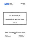
VB.Fuel and Governin2 System
fII
The fuel and governing system is the main operating section of the diesel engine . It is
composed of the fuel delivery pump, (uel filter, injection pump.. governor, fuel injection and fuel
pipes,
return
etc.as
shown in Fig. 10.
The
fuel
is
2
pu,nped by the fuel
delivery
pump
1_~_--3
from
the fuel tank into the
pump
injection
through the fuel tilter.
The
diesel
fuel
is
delivered through the
injection
high
pipe
under
.. pressure
produced in the plunp..
and is then atomized
by the injector before
burning
in
the
Fig. 10 Fuel and governing system
1. Fuel return pipe 2. Fuel injedion pipe 3.lnjedor
4. Injection pump S. Fuel filter 6. Governor 7. I"'uel delivery pump
combustion chamber.
The fuel delivery
pUlnp is a single-acting piston type pump located on the outside of the injection pump. The
eccentric caln,\\'hich is set on the camshatt of injection pump"dnves the thet delivery pump..
\vhich finally presses the fuel into the fuel cavity in the injection pump_
5-7
'fhe inj-ectionpump has been calibrated by the manufacturer.Be sure not to dismantle it at
\vill. When the. dismantlementrepairment and adjustnlent are required,it is t()rbidden to
inter("llan~e'the
-pluger sets-and discharging valve sets,and,<be sure to keep clean\-vhen
assembling.
:'rheall speedmcchanical- centrifugal governor is applied. l'he governing handle can be
opemled: -tocontroJ the speed -of diesel
en~ine~When
the governing handle is turned in the
direction of tightening the governing spring"the fuel supply \vould increase and the engine speed
would be up consequently. When this fllel supply \vould dec·rease and the relevant engine speed
\vould go do\-vnJ)o not move either the high speed or the idling speed, set scre\\'s or screw the
rnaxinlal,fuel supply set screvv.on the governor at will
d~ring operating.
On the governor housing,a stop handle is mounted which'lif necessary,can be operated to
stop the engine at clnergencv.
'rhe necdlcvaive and its body.are a precise set lapped in c;ouple .,theretore,closc attention is
paid to that,\\'hen dislnantling and assenlbling thenl.Be sure not to interchange them and to keep
them clean.
.'
\I. LubricatioeSvstem
l'hc lubricating system is composed of the strainerj)ube oilpurnp,oil filter and pipelines,as
sho\\'n in Fig.II..
l'he engine adopts pressure and splash
Jubrication.l~he pressure
lubrication is applied to the
main bearjn~connectin~-rodbearing,carnshaft bushing.The cylinder sleeve,piston.,piston pin.,
connccting- rod bushing.. camand its tappet,as l.vell as valve 'and its guide are lubricated by
splashed oil
spray.'Thl~
bearings f(lr the \vater pump shaft are lubicated regularly by adding
lubricating grease.
rrhe luhe oil is
slu:~ked
up to the lube oil pump frotn the oil sump through the strainer and
the oil inlet pipc,and ,pumped into Inain oil ,line through the oil ti Iter. ()nc path of the lube oil
luhricates the lnain beari-ng and the connectlngurodbearingthrough the oH hole on the crankshaft:
other path of the oil
'ubricat\~s
the camshaft bushing.. and also
~he
oil is supplied intermittently to
the rocker arrn shatl bushing throrgh the eccentric oil channel in the rear journal of the camshaft;
and the third path of the oil is ted to the
tilnin~
idler bearing.-rhe lube oil pUlnp is of slantingly
Inounted type.A single sta~e paper cartridge 011 pUlnp is used.The filter element can be replaced
regulariy.ln case of blockin~up durin~_ xoperation.,the oil
5-8
tlO\VS
into the main oil line by opening
the safety valve while the oil tilter loses the function of filtration,so it is necessary for the
cartridge to be cleaned or replaced regularly accordin~ to. the maintenance.
..---IO
.____'1,ih.IIJIii.'IIi.....
11
14
4
Fig. 11 Lubricating s)'stem
1. OU IUIIlp 1. Stralaer 3. Lube 00 pump 4.. Piston and cOnDectiDg- rod assembly and cyUnder Uoer 5. Lube oil
ftlte.· 6. Gear traiD 7. Oil pressure puge 8. Rocker arm 9. Valve push rod, valve tappet and block hole lur
tappet 10. Rocker ann shaft 11. Valve and valve guide 12. Camshaft and bushing 13. Oil lines in the block
14. CraDbIaaft and bearing
",
5..9
IX . Coolin! System
The
cooling system
is a
forced
cir,eular water cooled type,as shown in Fig.
1
] 2. '[he systern consists of a radiator, water
lhn,thermostat
punlp.. cool ing
,/
and
diversion hood"etc.
'fhe cooling water,pumpcd fr0l11 the
radiator into the cyJinder block water
gallery .Jlo\vs tangentially and round to
the cylinder IIner"then up to the c.ylinder
head. The hot water from the front end of
cylinder head
tlO\VS
.
Fig. 12 Coolina. system
back into the radiator
1. Radiator 2. Thermostat. 3. Cooling fan
4. "'ater pump S. Inlet water pwnp
through the thennostat and outlet \vater
pipc.\\'hcn the tClnperature of cooling.
water is beJ()\\' 70 '{..:~ ,the thermostat closes"and the cooling waterwiH be short-cut for circulation
from the hranch ,vater 'pipe on the front end ofthe cyJ inder head to the water pUl11p Inlet pipe and
the water punlp:'when the temperature of the cooling water is above 70 ,_. - 80 '(; .Jhe thennostat
opens,and the cooling water flows into the
UpPt'f
part of the radiator through the t.hernlostat and
tlows do\vn\vard the· thermostat and flows downward along the flat- tube Into the lower part of
the radiator.. during \-\:hich the cooling \vater is l.'ooJed by the fan andcOTnpletes the regular
cir(·tllation 'l'ht c()oltng
T'he
~entrifugal
t~ln
can be \)1' either suction or hlast type according to its application.
,vater pUInp i~ driven by lhe fan belt on the crankshaft pulleyJn (~ase of
severe \-vater dropping out [forn the \veep hole at the lo\ver part of the purnp housing due to the
danlace of \vatcr seal
durirl.~
opcralion.. it is necessary to repJacl' the water seal hut blocking the
weep hole at tht: ttlne of leakage is not pennitted,or the \vatcr \\'ill
111USt
op~ration.
pUI11p
grease
\vh~ch
into the
hcarjngs~which
beconsidert:dwhile abnormal noise occurs during
causes their quick ,vear.Replacenlent
'fhe grease nipple of \vater
e~ltl~r
Innst be tilled regularly \\'ith ZG- 4 calcium based
HJnOunts to abollt 1/2-" 1,3 of the capacity of bearing cavity according to the
Inaintenanc('.r!H~
bearing wi II be overheated
thcnnostat \v ith
corrllJ~ated
pipe is ti lied
v\'i~h
\,\1 ith
excc:,sive grease. 'I'he single valve type
tt~lnperature-
sensitive fluid \\'hich can
automatically control the valve opening and closing.
'rhe fan belt Inusr be checked and adjusled n.:auulartv ti)r
proedures for the rnaintenance.The slack is
if}
20
and the dynalTIo pulleys.
5-10
n~
tension
nIH. \vhen pres~jing
~H..:cordin}~
the belt betlvecn
to the
th~
filn
':X' • ,Electric; System
The electric system is composed of the battery,starting motor,dynamo,electrothermaJ plug,
starting button and instruments,etc.,as shown in Fig.13.
The parallel excited silicon rectifYIng dynamo model JF 11 comprises the three -
8
phase
9
=
Fig. 13 F;lectric system
1. BaUery 2. Starting motor 3. Wire 4. Glow plUI 5. Preheating and starting
switch 6. Galvanometer 7. Ignition switch 8. Regulator 9. Dy~mo
alternator and silicon diode rectilier.Be (;areful that HOle arnlaturc nlust be negitive pole grounded,!
or the dynanlo \viJl be damaged.
Refer to operation and lnaintenance Inanual for JF senes silicon rectifying dynamo for the
operation and maintenance ofthe dynatno.
t\fter turning on the starting switch"the Hy\vheeJ 'gear ring IS engaged \vith the 111otor pinion
by the solenoid,lneanwhile the flywheel is driven oy closing the current (~ircuit of starting Inotor.
.As soon as the engine is
started~thc
starting
s\~/ltch
111ust he turned off ilTIlncdiatel) .'rhen the
core along with the pinion returns to the original place under the actuation of spring. "'he
continuous
\-vorkin~ titnt.: f(Jr
the startIng lTlolor should not exceed 15 seconds,'Thc interval
het\veen t\VO startin.g operations IS 2
.3 Ininutes. It. i" ncceSSdlY to check and eliJn}llate the faults
in case of starting failure t;)r three atlclnpts. l'hc electrifying tlJne of the glo\\' plug each tl1ne
during operation
IS
not permitted
to
be over 30 seconds.
5-11
SECTION 6. FAULTS AND REMEDIES FOR DIE'SEL~ENGINE
I .Hard or refuse to Start (see Table 4)
Table 4
··.·-----·-----··--·-··-·-f·--··-···-·- .
Causes
.- ....•.•.. ,..
- '
_ _-_ -.-"--
_,- -----_
_--,-,_.~
_,"".-
-
-..
•..
,----_. --- .._
1.Fuel fitters and fuel pipelines bolcked.
,I
~----.-~.,,-
_-_ _ _-.-._---_
1.Clean.
-_._.I
~-
.--.
..
_._ _-._ ---._.
Remedies
-.--,
.•....
2.Exhaust air and· tighten· all fuel pipdline connector.
2.Air trapped in fuel system.
3.Advanced fuel injection angle incorrect. 1 3.Readjust it accoi'ding to specifications"
_.:::-'.- ·
•. · · · i
4.Fuel spray abn0rmaL
~·l
~.
4.Readjust fuel injection pressureaccgrding:~~, . specifica-
; tions.~ eleanor replace·i$jector needle 1'alve sets.
5~Compression
preessure 10\\1.
! 5.Cheak or replace piston rings,and cylinder liners.
L.
6.Valve lash incorrect
Grind'valves.('Ylnder·head nuts should be tightened in
case of leakage on, cylinder.head. ~~~kets.
6.Adjust it ·accordingt()-speci!i~k>.'skind align gear
~.,.;~~,,;.
..~'"
!;.:"
~:
marks.
7.Battery charge insuffcient.
7.Charge it.
8.\Vire connections loosened.
8.Checkand,tighten wire connections. Clean up contact
"points.
9.Ambient temperature too lo\v, and oil
'9.Preheat cooling water and"lube oil:'
too viscous
II . Power Instlfficient(see Table 5)
Table 5
Remedies
Causes
l.{}ompression pressure inside cylinddcrs too low.
2.Advanced fuel injection angle incorrect.
3.\'ah.rc lash incorreCt.
4.Fuel suppjy fe)1' each cylinder unbalanced.
5.I\ri, filter clo¥cd.
6J:uel injection punlps. fuel i'1iector sets worn off
or fuel. injection pressure incolTt.~t.
7. Rotatf~n speed incorrect.
I.Reterto iteln 5 in paragatph y. and replace
comPQn(..~ts excee~iingwear IiUlit.
2./\4iust it according to specHications.
3.Adjust it according to specifications.
4.Adjust fuel injectionpulups to proper supply.
5.(:lcan.
6.Rcplace thClll with nc,,,, sets~ aqjusi filel injection
pressure and check fuel spmy.
7A~just it
sJ..~~citicd
6-]
\\lith speed governing handle in Ordt..T to rench
speed.
ill.Smokio2 Exhaust (see Table 6)
Table 6
Causes
Remedies
1.Engines overloaded.
I.Reduce the load properly and in
caSt~
of unsuited
Inatching. adjustment should be Inade.
the injection pressure and fuel spray. Replace
'then in case of damage. 3.Use qualified fuel.
4.rv1ainly caused by unqualifiedfue'linjccto~~ incorrect
advanced fuel injection angleJeakageatcytinder'hcad
gaskets and low compression pressure.Remdy~it1·
accordance with specific problems.
2.('ht~ck
2.Fuel il1iectors not well atolnized
3.Fuel unqualified
4.Colnbustion incomplete
lV.Knockin2 Noise in Entdne (see l'able 7")
Table .7
Causes
J .Advanced
Remedies
1.ReacUust it according to specitlcation.
fuel injection angle incorrect.
2.Air trapped in fuel systems.
2.Exhaust air.
3.Fuel supply for each cylinder unbalanced.
3.Readjust fuel supply.
, 4.lJse qualified supply.
4.Fuel unqualified.
5.Wear of certain
j
.
cOlnponent~ exceeds
lilnits
I 5 J{eplace thelTl
V .Lube Oilln~ufficientor No Pressure (see l'able 8)
Table 8
Causes
Renedies
1.0illevel in oil sumps too low.
2.Serious leakage from oil pipelines.
3.0il strainers,oil filters and pipe'lines clogged.
4.011 gauges damaged or gauge lines clogged,
5.0il too thin.
6'()iI pump gears seriously v;'om otf'i\\rjth excessive
clearance.
7.Pressure relief valves of oil filter cease to filnction.
8.Main bearings, connecting-rod bearings and carnshaft
hushings seriously worn off\\ith excessive clearance.
6-2
]./\dd oil up to lnark line on dip sticks.
2.Eliminate leakage.
3.Clean and replace elelnents if ne'··essat)'.
4.Check and replace elenlcnts if necessary
S.llse qualified oil"
6.i\djust the clearance or replace thelli.
7,(~heck and repair or readjust thenL
8.Check and repair or replace thC1TI,
MANUFACTURING UCENSE: XK06 -205 -00141
PRODUCT STANDARD:Q/321284 JCA03(35) -2002
NO. OF EXPORT UCENSE FOR QUALITY: 2000112013
UCENSE APPROVAL DATE: OCT. 10,2000