1
Dice::
ELECTRONICS
for selected AudiNolkswagen vehicles
Installation Guide/User Manual
for model number AudiNW-CDC and AudiNW-SAT integration kits
~DICE::
~~ ~3
'" • . - - E L ;;-: C T R D
f C
Copyrights and Trademarks
Copyright 2009 DICE Electronics, LLC.
The DICE Electronics logo is a trademark of DICE Electronics, LLC.
iPod is a trademark of Apple, Inc.
All rights reserved.
Printed in the U.S.A
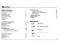
Table of contents
Copyrights and trademarks
Icon legends
Warranty and safety
Product registration
Supported iPod models
iPod hierarchy
Charging
3
3
4
5
6
AudiNW-CDC integration kit
Integration kit contents
DIP switches
DIP switch settings
Installation
iPod audio source
Controls in CDC emulation
Browsing function in CDC emulation
8-19
9
AudiNW-SAT integration kit
Integration kit contents
DIP switches
DIP switch settings
Installation
20-29
7
iPod audio source
Controls in SAT emulation
Browsing function in SAT emulation
Scrolling feature
Auxiliary audio source
Troubleshooting
Disclaimer
7
10
11
12
Icon legends
0'\
Turn jog dial
0'\'\'\
Turn jog dial repeatedly
18
18
19
21
~
c:;s;:
Press button
Press button repeatedly
22
23
24
Scroll
28
28
29
30
31
33
35
Warning and safety!
Please read these instructions carefully before proceeding. Failure to follow instructions may result in improper operation
or injury. Neither DICE Electronics, LLC. nor Apple Inc., its regional offices, distributors or resellers take any responsibility for
any damage or injury as a result of using the integration kit.
- Do not open, disassemble or alter the interface in anyway.
- Do not insert anything into the casing.
- Do notcutortrytoaltercables in anyway and always usethe correct connections.
- Only operate unit when stationary or ask passengers to operate itforyou.
- Do not allowthe Apple iPod to distract you from driving.
- Exercise goodjudgementand keepyoureyes on the road atal! times.
- Do not expose unit to extreme temperatures, humidity or shock.
- Keep the unit and iPod away from fluids.
- Keep away from children! -Interface components may contain small parts, can be broken or disassembled and
components may become loose from vibration and heat. Small components and packaging materials may be a chocking
hazard when handled bychildren.
Congratulations on your purchase
Thank you for purchasing the DICE integration kit for iPod. Please review our user manual and installation guide before
operating the unit. This interface was designed and manufactured to seamlessly integrate with your vehicle's factory
entertainment system.
Product registration
In order to validate your warranty period and to receive telephone or online support, you MUST register your DICE
product.
To register your DICE product, please complete the following steps:
1. Visit http://www.diceelectronics.com/register
2. Complete the product registration form.
3. Submit the form.
4. Save the registration/support/warranty sheet in a safe place for future reference.
If you are unable to complete the registration via internet, please call DICE Electronics at 1-888-342-3999.
~Dlce::
.. ·.-ELECTRON!CS
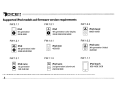
Supported iPod models and firmware version requirements
FW:3.1.1
[0)
O
iPod
4th generation
20GB 40GB
FW:1.2.1
[~]
O
iPod
4th generation color display
20GB 30GB 40GB 60GB
FW:1.0.3
[I ~ I) iPod classic
@
80GB 160GB
FW:1.2.1
FW:1.4.1
FW:1.0.3
-.T.,
iPod
O
5th generation (video)
30GB 60GB 80GB
101
@
[I ~ II
@
~
FW:1.3.1
o
[1-T..1) iPod nano
1st generation
1GB2GB4GB
iPod mini
4GB 6GB
FW:1.1.3
II-T..II iPod nano
@
2nd generation (aluminum)
2GB 4GB 8GB
iPod nano
3th generation (video)
4GB 8GB
FW:1.1.1
D
iPodtouch
8GB 16GB 32GB
o
For the latest firmwa re versions and models not Iisted, please contact you r authorized dealer or DICE Electronics, LLC.
~DICE::
... · I I I E L E c T R o N l c 5
iPod hierarchy
By default, the interface creates a Playlist having a name that is the same as the name
of the iPod.This Playlist is the very first on the list of Playlists shown while browsing in
Playlist mode. This Playlist contains all the songs on the iPod. Once a Playlist is active
an Artist may be selected within that Playlist using the Artist Mode. Albums by the
selected Artist and within the selected Playlist may be selected in Album Mode. "ALL
ARTIST" and "ALLALBUM" designate all available content in those categories.
Song
Charging
The interface automatically charges the battery of the iPod when
connected and the key is in the ACe/ON position.
Charging icon will appear
I---I---I---j0n the upper right corner
of the iPod screen to
indicate charging.
AudiNW-CDC integration kit
~DICE::
... ·JIIIELECTROi'-.JiCS
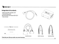
Integration kit contents
1Vehicle specific interface unit
1iPod docking cable
Vehicle specific harnesses (R,Rl ,R2)*
1User manual
~ilierf2ce i~f iPtnt
for selected AudiNolkswagen vehicles
Audi-R harness
* Note that your kit may contain one or more harnesses.
VW-R 1 ha rness
VW-R2 harness
~Dlce::
.'111
E LEe T"R [} N i C S
Dip switches
The configuration switches located on the DICE module are used to set the operation of the interface by the installer.
Incorrect dip switch settings may cause the DICE interface not to work properly or not to operate at all. Disconnect the
vehicle harness from module and cycle ignition oHfor 50 seconds after changing the switches!
~I_IOFF
~1_loN
1
2
DICE Module
ON/OFF Switch Positions
"Car (onfig. "iPod (onfig.
Switch"
Switch"
. Dice::
\t
t:'
L.
i
'-
E_
I""<
L<
T,
,'nl:
n
C..,;
,~:
....j
;~
L.<
C
-..;
Dip switch settings
iPod configuration switches
Car configuration switches
Settings
Settings
"Locked"
CD changer (CDC)
Dip switch 1
OFF
Dip switch 2
OFF
Switches should remain in the default OFF
position.
"iPod"
Dip switch 1
Dip switch 2
OFF
OFF
It is best selected when advanced
controls on the radio are used.
After the initialization the iPod will
be locked for an increased
interface functionality.
Dip switch 1
ON
Dip switch 2
ON
It is best selected when text display
is not supported by the radio and
user wishes to retain iPod control.
Track numbers and times are not
synchronized between the iPod and
radio. Because there is less data
transfer between the iPod and radio,
this mode has the fastest response
time. Content is selected on the
iPod.
UU
OFF
Default
OFF
UO UO
FF
Default
FF
~ON ~ON
~DICE::
ELECTf'<O~;:GS
•• . . .
Installation
Installation should only be performed by a qualified professional. Beware of sharp edges to avoid injury and exercise
caution when removing trims as they may break. The module should be placed at an accessible location to allow AUX cable
to be connected, such as in the glove box, the center console or underthe front seat.
1 Pull vehicle into service bay and access radio/center console.
2 Disconnect both battery terminals. These cables must be disconnected during installation to ensure proper initialization
ofthe mod ule when it is con nected. Make sure that radio code is available before starting installation.
3 Before pulling out the radio, remove surrounding trims and screws. Most trims can be removed by carefully pulling on
the piece or using trim removal tools. Trim is usually held in place by snap-in clips.
4 To remove the radio you need to use the appropriate radio removal tool. Consult your dealership if
additional information is needed on removing the radio.
Sa - Audi radios with Rconnectors - You can access the CD changer connector located on the back of the radio. Unplug
the factory connection if present and plug the Audi-R BUS connector into the receptacle. The
connector should securely lock. Ground wire MUSTbe connected to a stable grounding point.
+--
Audi-R connector
to ground
receptacle
to interface
module
factory harness
in vehicle
~DICE::
-·IIIIFLECTRONlC5
Sb - VW radios with Rl connectors -You can access the CD changer connector located on the back of the radio.
Unplug the factory connection if present and plug the VW-Rl BUS connector into the receptacle. The
connector should securely lock. Ground wire MUST be connected to a stable grounding point.
VW-Rl connector
to ground
to interface
unit
Sc - VW radios with R2 connectors -You can access the CD changer connector located on the back of the radio. Unplug the
factory connection if present and plug the VW-R2 BUS connector into the receptacle. The connector should securely
lock. Ground wire MUST be connected to a stable grounding point.
0
0
0
0
0
~
@ @
0
0
0
0
1001
o
to ground
VW-R2 connector
to interface
unit
~Dlce::
·.-ELECTRO;\~lCS
..
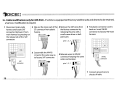
Sc - Cable modification (only for i-VW-R kit) -If veh ide is eq uipped with factory Satell ite rad io and desired to be retai ned,
a harness modification is required.
1 Disconnect main radio
harness and locate SAT
connector. Remove it from
main harness by pressing on
the release tab of the SAT
connector.
;;1
~ ttEHE
~
,lr
G
1_
2 Slide out the inner part of the 4 Remove the SAT wires from
SAT connector from plastic
the factory connector by
releasing the pins with a
housing.
small screw driver or ballpoint pen.
pins 1,3,7
3 Disassemble the VW-R2
connector the same way as
the factory SAT connector.
;;1
~
~ffiEEB
5 Relocate wires to VW-R2
connector keeping the same
order and location.
SAT
connector
6 Put plastic connector covers
back on.lnsertVW-R2
connector to factory VW main
harness.
pinsl,3,7
G
VW-R2
connector
~
t )11"",
7 Connect ground wire to
chassis of radio.
6 Connect the vehicle specific connector and the iPod docking cable to the DICE module. Apply cable ties to secure
the cables.
0··
1/8"
iPod
dock
input cable
input
AUX
•••
••
000000
000000
receptacle
receptacle
vehicle
specific
connector
iPod docking cable
vehicle specific connector
7 Verify that all connections have been properly made.
8 Reconnect the carls battery. Test the unit before seating the cables and reinstalling the panels/trim.
iPod audio source
Controls in CDC emulation
Press the CD button to access the interface and its features. Pressing this button repeatedly will cycle through sources
present (internal CD if present, followed by external) in your vehicle. When the iPod audio source is active (DISC 5,
Track1 ),press theTrack button orturn theTune dial to select next/previous Song.
Audl symphony
\
~
HLOAD
=
=
I
<3
~1
1
CD EXT
CD 01:52
CD EXT 4<3
1>2 CD EXT
TRACK 12
CD EXT 5<3
Only with AudiNW-CDC kit
II
I>
Press to change
f-+--+-----jTrack,
hold to Rewind
J
or FForward.
1=
I
=
Source
selector
I
--l' -+ I CDC CD1 TR1
TRACK MODE-
PLAYLIST MODE -
ALBUM MODE -
_D_IS_C_1
'------D_IS_C_2_1-+
I DISC 3 1-+
ICDC CD2TR1
I CDC CD3 TR1
(within the
selected Playlist)
CHAPTER MODE
~>or
,...,...- "-- \
~>or
,...,...- -"- \
~>or
--
-I
DISC 4 1-+
I CDC CD4 TR1
(within the selected
Audio book)
AUDIO SOURCE -
,...,...- -"- \
I DISC 5 1-+
I CDC CD5 TR1
,...,...- " -
\
~>or
,...,...- -"- \
~>or
Only with AudiNW-CDC kit
AudiNW-SAT integration kit
~DICE::
• • " ' E LEe T f? 0
N I C S
Integration kit contents
1Vehicle specific interface unit
1 iPod docking cable
Vehicle specific harnesses (AudiNW-CAN)*
1 User manual
mCi: '~!tfiri~c~ filr iP~i
for selected AudiNolkswagen vehicles
AudiNW-CAN harness (type 1)
AudiNW-CAN harness (type 2)
* Note that your kit may contain one or more harnesses, in some cases they may look different from the ones illustrated above.
~DICE::
·~ELECTr~[Jr<iC~3
...
Dip switches
The configuration switches located on the DICE module are used to set the operation of the interface by the installer.
Incorrect dip switch settings may cause the DICE interface not to work properly or not to operate at all. Disconnect the
vehicle harness from module and cycle ignition off for 50 seconds after changing the switches!
DICE Module
~1.loN
2
ON/OFF Switch Positions
"Car Cantig. "iPad Cantig.
Switch"
Switch"
. . "c
~DICE::
f~
~~
L.. E C T
0
;-·1 1 C
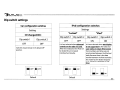
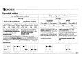
Dip switch settings
Car configuration switches
iPod configuration switches
Settings
Settings
Multi-line display (Default)
for Audi models
forVW models
for Audl models
for VW models
Dip switch 1 Dip switch 2 Dip switch 1 Dip switch 2 Dip switch 1 Dip switch 2 Dip switch 1 Dip switch 2
ON
OFF
OFF
OFF
This is the recommended setting
for radios that have multiple text
fields displayed in Satellite
emulation mode.
OFF
ON
ON
ON
This setting is recommended for
radios where there is only 1 text
field displayed in Satellite
emulation mode.
Recommended for Satellite (XM/Sirius) capable radios. This type of
emulation provides full text display on the radio. If Satellite (XM/Sirius) is
equipped it must be disconnected to operate integration in this emulation
mode. XM/Sirius receiver is usually located in the trunk or under the
passenger seat.
n
~ OFF
MONU
for Audi only
~OFF
U
U MON
U
forVWonly
Dip switch 1
Dip switch 2
OFF
OFF
It is best selected when text
display is supported by the radio.
After connecting the iPod you will
see a logo or a checkmark
indicating that the iPod is locked.
After the initialization the iPod will
be locked for an increased
interface functionality.
n nn
~OFF ~OFF
for Audi only
~ON
.ON
forVWonly
"iPod"
"Locked"
Single-line display
Default
Dip switch 1
ON
Dip switch 2
ON
It is best selected when text display
is NOT supported by the radio.
Track numbers and times are not
synchronized between the iPod and
radio. Because there is less data
transfer between the iPod and radio,
this mode has the fastest response
time. Content is selected on the
iPod.
Installation
Installation should only be performed by a qualified professional. Beware of sharp edges to avoid injury and exercise
caution when removing trims as they may break. The module should be placed at an accessible location to allow AUX cable
to be connected, such as in the glove box, the center console or under the front seat.
1 Pull vehicle into service bay and access radio/center console.
2 Disconnect both battery terminals. These cables must be disconnected during installation to ensure proper initialization
of the modu Ie when it is connected. Make sure that radio code is available before starting installation.
3 Before pulling out the radio remove surrounding trims and screws. Most trims can be removed by carefully pulling on
the piece or using trim removal tools. Trim is usually held in place by snap-in clips.
4 To remove the radio you need to use the appropriate radio removal tool. Consult your dealership if
additional information is needed on removing the radio.
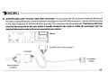
Sa - AudiNW radios with "Y-harness" type CAN1 connection -You can access the SAT connector located on the back of
the radio. Unplug the factory connection if present and plug the AudiNW CAN connector in. Connect the factory plug
to the cable receptacle if it was removed from the radio. The connector should securely lock. The factory SAT tuner
must be disconnected at the tuner which is usually located in the trunk or under the passenger seat. For
detailed information refer to the service manual of your vehicle.
'llI--
AudiNW-CAN connector (type 1)
receptacle
to interface
module
factory harness
in vehicle
. Dice::
~
.... T R .....
,-, ,.....
_c I__ E C
LJ !'..'
,< :, ,_:;:,
~-
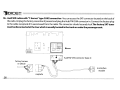
Sb - AudiNW radios with "Y-harness" type CAN2 connection -You can access the SAT connector located on the back of
the radio. Unplug the factory connection if present and plug the AudiNW CAN connector in. Connect the factory plug
to the cable receptacle if it was removed from the radio. The connector should securely lock.The factory SAT tuner
must be disconnected at the tuner which is usually located in the trunk or under the passenger seat.
o
o
0
0
o
~
o
IGGI
o
o
~--
AudiNW-CAN connector (type 2)
factory harness
in vehicle
to interface
module
receptacle
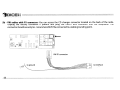
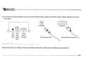
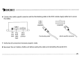
6 Connect the vehicle specific connector and the iPod docking cable to the DICE module. Apply cable ties to secure
the cables.
_0-..
••
receptacle
1/8"
iPod
AUX dock
input cable
input
vehicle
specific
connector
iPod docking cable
receptacle
vehicle specific connector
7 Verify that all connections have been properly made.
8 Reconnect the car's battery. Test the unit before seating the cables and reinstalling the panels/trim.
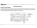
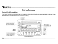
iPod audio source
Controls in SAT emulation
Press the SAT button to access the interface and its features. When the iPod audio source is active (Mode 5, Channell), use
theTrack button or theTune dial to select next/previous Song.
Source
indicator
I
~I
This text field may not
be shown on all radios.
I---. t-----
EJ
On selected radios you /
may use these buttons
to select Modes 1-6.
SAT
A
SNGTITL
OUl
1[
rOf
VOL
004
003
uu..!
BASS
0
MIDDLE
0
TREBLE
0
Press to cycle
through Modes 1-6.
v
005
006
A
SEEK
TRACK
-J[- -1[-IEll
-
EJECT )
CAT
FLDR
"'ARTIST * ALBU'M)
~
r
(
XM 1 001
I~N
Source
selector
I
BALANCE
0
Only with AudlNW-SAT kit
v
SCAN~
FADER
o
~
TUNEV
Press to
change
Track.
Turn to
change
Track.
. Dice::
~
ro",
,"". " -EC~'RnNI-'C;
.
I.
'--"
t .• '-'
Silverline browsing function - in SAT emulation
The Silverline integration kit features content browsing. After connecting the iPod, select the desired browsing mode by
pressing the appropriate CAT/FLDR button. Press the SeeklTrack button or turn the Tune dial repeatedly to browse
contents; 1second after releasing the button, your selection is executed.
XM 1 001
TRACK MODE-
SONG 1
ARTIST' ALBUM
C:~
XM 1 001
PLAYLIST MODE -
PLAYLIST 1
PLAYLIST
C:~
XM 1 001
ARTIST MODE (within the
selected Playlist)
ARTIST 1
ARTIST
C:~
XM 1001
ALBUM MODE(within the selected
Artist in the selected Playlist)
AUDIO SOURCE -
ALBUM 1
ALBUM
....
orru~O~
i'
or,~,O~
i
.... orru~O~\
i'
SEEK
T
"
""
~-
"
SEEK : '
"
SEEK
T
""
-.
i-: orru",O~
SEEK
K ,-
SONG 3
ARTIST' ALBUM
C~~
-.
XM 1 001
PLAYLIST 5
PLAYLIST
C~~
-.
~-
""
XM 1001
XM 1 001
ARTIST 8
ARTIST
C~~
-.
XM 1 001
ALBUM 4
ALBUM
C:~
XM 1 001
IPOD
SEL: IPOD
C~:J
i: orru",O~
SEEK
T
Only with AudiNW-SAT kit
"
,-
AUX audio source - see pp.31-32
-.
XM 1001
AUX1
SEL:IPOD
~DICE::
·.-ELECTRC>-J~CE3
..
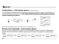
Scrolling feature - in SAT emulation, Mode 6
(Only with AudiNW-SAT kit)
To set and change scrolling feature press CAT/FLDR button repeatedly until Mode 6 is selected. Change options by
pressing SeeklTrack or turning the Tune dial. After setting the desired feature turn off the ignition for at least 50
seconds to engage the new selection.
XM 1 001
SHORT SCROL
SOFTWARE VERSI
XM 1 001
XM 1 001
SHORT STAT
LONG STAT
SOFTWARE VERSI
SOFTWARE VERSI
XM 1 001
LONG SCROL
SOFTWARE VERSI
Certain amount of blinking is normal on some radios when the scrolling feature is on.
Firmware version information - in SAT emulation, Mode 6
Firmware versions are displayed while in Mode 6. This may be needed by a support technician if troubleshooting is
necessary. Having this information ready before requesting technical support may expedite the troubleshooting
process.
XM 1 001
(
CAR 1.00
XM 1 001
J
SHORT STAT
c~~
(
IPOD 100
XM 1 001
J
SHORT STAT
C~~
(
AUX 100
XM 1 001
J
SHORT STAT
C~~
(
SHORT STAT
CORE 1.00 " )
~=:::;::::oo-'o<.-_-----'
~DICE::
" ., I11III
~,j
E LEe T R 0
!
r:
5
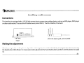
Auxiliary audio source
Connections
The interface is equipped with a 1/8"AUX jack connection to connect an auxiliary device, such as an MP3 player, DVD player
or other audio source. To access the AUX audio source, select DISC 5, Track 2 or Mode 5, Channel2.
000000
000000
1/8" AUX
input
1/8" mini stereo jack, not included
Making the adjustments
While listening to the auxiliary device, adjust the volume (gain), bass, mid and treble by turning the Tune dial or pressing
the Seek button. DISC/Mode 1-4 modes select what adjustment the Tune/Seek buttons perform. See illustration on page
32.
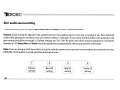
AUX audio source setting
The auxi Iia ry in put has setti ngs for gain, bass, mid and treble in order to opti mize sou nd.
Volume (Gain) should be adjusted if the audio level from the auxiliary device is too low or to high. If you hear distorted
audio while playing the auxiliary device, you need to reduce (-) the gain. If you notice that the audio is too quiet then the
gain setting should be increased (+). Default settings are "50 ("68" for gain) and values may be adjusted in increments
between 01-99. Bass, Mid and Treble should be adjusted to compensate forthe acoustic presets ofthe radio.
11
Note: Ifyou are using an AUX device that is using the vehicle's power source and not its own battery, you may have to use a
GROUND-LOOP isolatorto avoid grounding and engine noise.
I 1 I
I 2 I
I 3 I
I 4 I
I
Volume
setting
I
I
I
Bass EQ
setting
MidEQ
setting
Treble EQ
setting
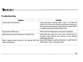
Troubleshooting
Problem
i
Solution
Cannot select the interface.
Check DIP switch settings (refer to pp.11, 23). With the
ignition OFF disconnect vehicle harness from modulefora
few seconds and reconnect. Verify that the correct button
is used to access the interface (CDC or SAT).
No audio from iPod source.
Reset the iPod. Verify proper connection to interface.
Reset iPod and make sure most recent iPod firmware is
installed. Check vehicle user manual on how steering
wheel controls work.
Radio/ steering wheel controls do not operate iPod, but Select DISC/Mode 5 and Track/Channel 1. Switch back to
DISC/Mode 1 andtrychangingTracks.
I audio is still present.
Radio/ steering wheel controls do not operate iPod.
Troubleshooting
Problem
Solution
Interface has erratic recognition or not at all.
Make sure that the ground wire harness is attached to
back of radio.
Text is not displaying.
Set iPod switches to OFF for "Locked" mode. Text display is
only supported on SAT-capable radios.
iPod does not charge.
Check all connections. Reset iPod and make sure iPod
charges while connected to computer orwall charger.
Music is distorted or sound level is too low.
Check and make sure all EQ and BASS boost options are
turned off on your iPod. (Refer to AUX settings on p.32)
~DICE::
... · I I J E L E C T R O N i C 5
Disclaimer and warranty
Important disclaimer, please read!
Unauthorized reproduction or reverse engineering is strictly prohibited! Intellectual property included is distributed under specific license
agreement with respective owners and is licensed only, not sold. No warranty, explicit or implied, is stated. Neither DICE Electronics, LLC., nor
any of its agents, distributors, dealers or vendors shall be liable for damages.
IN NO EVENT SHALL DICE ELECTRONICS' LIABILITY EXCEED THE PRICE PAID FOR THE PRODUCT FROM DIRECT, INDIRECT, SPECIAL,
INCIDENTAL, OR CONSEQUENTIAL DAMAGES RESULTING FROM THE USE OF THE PRODUCT, ITS ACCOMPANYING SOFTWARE OR ITS
DOCUMENTATION.
Warranty and Support
Products carry a 90 day limited warranty that protects you from defects in material and workmanship of products sold by DICE Electronics, or
its authorized agents, distributors and dealers. The warranty period begins the day a product is purchased by the end user. Products found to
be defective during the warranty period will either be repaired or replaced by DICE Electronics at no charge unless warranty is void.
Unauthorized attempt of repair or alteration of the product in any way immediately voids this warranty. Warranty does not extend to
cosmetics or finish. A DICE product specialist must determine that defect is present in the product and issue an RMA. Be sure that all wiring is
connected as described in the user manual and all related equipment is functioning properly. DICE Electronics disclaims any liability for
other incurred damages resulting from product defects. Any expenses in the removal and reinstallation of products are not covered by this
warranty.
If experience any problems or need help, please contact your local dealer or call 888-342-3999, or visit our support site at
http://www.diceelectronics.com/support.
~J;lEIJ;;~I; ;
AudiNW compatible integration for iPod
www.diceelectronics.com
AudiNW-iPod 2009-03
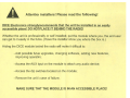
Attention installers! Please read the following!
DICE Electronics strongly recommends that the unit be installed in an easily
accessible place! DO NOT PLACE IT BEHIND THE RADIO!
Whether the unit is professionally or self installeCJI, put the module where you, the end user
can get to it easily in the future. (Have the installer show you where the box is.)
Hiding the DICE module behind the radio will make it difficult to:
- Add possible future upgrades, changing software, adding new features,
improving operation;
- Access the AUX input on the module to attach any audio device;
- Access the dip switches located on the module;
- Remove the unit in case of failure.
MAKE SURE THAT THE MODULE IS IN AN ACCESSIBLE PLACE!
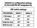
Updated car configuration settings
for the AudiNW-SAT integration kit
DIP switch settings
Vehicle/Radio
Switch 1
Switch 2
Volkswagen
OFF
OFF
Beetle
ON
ON
Single line Audi
OFF
ON
Multi line Audi
ON
OFF
READ BEFORE INSTALLATIONl
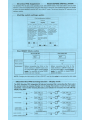
Silverline PRO Supplement
The Silverline PRO kit adds a new operating mode called SMART Mode. THis mode allows users to switch
between Locked and Display Modes using the Hold button on the iPod. This supplemental guide only applies
to users who have selected to set the DICE kit to SMART mode. This is done using the DIP switches on the
interface module.
iPod Dip switch settings update
iPod configuration switches
Settings
Locked
Dtps\wch1
f--- OFF
Display
I
Dlpswtch2
I
IDtps.wuch 1 IDp~wltdl2
ION
OFF
Smart
OFF
ION
ThIS mode should be
ThIS mode should be
selected when
selected when
browsing is prefered controls on the
fnom the radio. Aner
iPod are prefered.
connecting the IPod
The radio can display
you WIll see the DICE the track narne but
has IIm'led blows,ng
logo on the screen.
Aner the Initiallzal,on
capablilles
the ,Pod will be
locked for an
ThiS mode IS ,deal on
increased Interface
rad,os Wlth single hne
functlonailly.
dISplay.
I
[JOFF LJOFF
Oip5'WI t chl
lo.pswtfc.h2
I
ON
In Smart' mode,
both 'Locked' mode
or DISplay' mode
ean be selected by
the user ITom the
,Pod when
connected.
~'~o,,~
.ON .ON
.ON
L...-o
Delaul
How SMART Mode works:
iPod hold ON
Radio control
.,;
iPod control
X
Explanation
iPod hold OFF
limited
Before connecting the iPod to the
DICE interface In SMART mode, turn
the hold switch .QM to enable ~
~. For operation in locked mode,
please see user manual.
Before connecting the iPod to the
DICE interface in SMART mode, turn
the hold switch QfE to enable display
~. For operation in display mode,
please see below.
NOTE: Changing the hold switch on iPod to ON/OFF must be done J2!iQr to connecting the dock cable.
DICE Silverline PRO browsing function - Display mode
The DICE Silverline PRO integration kit features browsing. After connecting the iPod, select
the desired mode by pressing Presets 1-6. To change Track press or tum the Tune button
repeatedly; 1 second after releasing the button, your selection is executed. The radio will only
display song titles.
-
TRACK MODE-
-
PLAYLIST MODE-
TRACK MODE-
ALBUM MODE (WllhIn the selected
MIst
In
the """'cted Playll8l)
AUDIO SOURCE• Numbers indicate sequence.
4
15(Jl) nFt1E (1 )*
C:;::::::J
15(Jl) nFt.1E (1 )
C:;::::::J
-
15(Jl) IlFt.lE (1 )
-
15(Jl) rmE (1)
-
~-~;.;,-:: ~
Of
C:;::::::J
•• TUNE-l
Of
C:;::::::J
II
iPod audio source
PO]
I :'~:~'~'li
or
O~
a
a
-15(Jl) m,t: (4)
C:;::::::J
-15(Jl) mtIE (11)
C:;::::::J
AUX audio source - see pp.31-32
-IFU)(I
I
••..
••
.
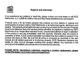
Support and warranty!
If you experience any problems or need help, please contact your local dealer or call DICE
Electronics. LLC. at 888-342-3999 or visit us at http://www.diceelectronics.comlsupport.
Products carry a 90 day limited warranty that protects you from defects in material and
workmanship of products sold by DICE Electronics or its authorized agents, distributors and
dealers. The warranty period begins the day a product is purchased by the end user. Products
found to be defective during the warranty period will either be repaired or replaced by DICE
Electronics at no charge unless warranty is void. Unauthorized attempt of repair or alteration
of the product in any way immediately voids this warranty. Warranty does not extend to
cosmetics or finish. A DICE product specialist must determine that a defect is present in the
product and issue an RMA. Be sure that·all wiring is connected as described in the user
manual .and all related equipment is functioning properly. DICE Electronics disclaims any
liability for other incurred damages resulting from product defects. Any expenses in the
removal and reinstallation of products are not covered by this warranty.
PLEASE NOTE: International customers requirin-9....LProduct replacement,W)lease
contact the dealer your product was purchased fromI