1
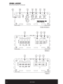
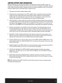
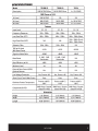
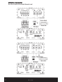
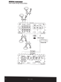
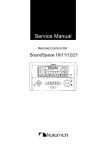
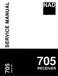
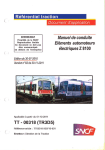
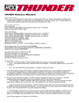
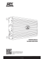
OWNER'S MANUAL
TO SERIES AMPLIFIERS
Use your smartphone to scan or visit
youtube.com/user/MTXThunderforce
to learn how to properly install this
amplifier.
MTX COM
PRODUCTINFORMAnON
Model# _ _ _ _ _ _ _ _ _ _ _ _ _ _ __
Serial# _ _ _ _ _ _ _ _ _ _ _ _ _ _ __
Dealer's Name _ _ _ _ _ _ _ _ _ _ _ _ __
Date of Purchase ______________
INTRODUCTION
Thank you for purchasing an MTX Audio Hi-Performance amplifier. Proper installation matched
with MTX speakers and subwoofers provide superior sound and performance for endless hours of
enjoyment whether you are waking the neighbors or just out enjoying your tunes. Congratulations
and enjoy the ultimate audio experience with MTX!
FEATURES
• Compact Size
• Double Sided PCB
• Surface Mount Components
• Mosfet Design
• LPF and HPF Crossover
• Adjustable Bass Boost
• Noise Free Design
• Short, Thermal, and High/Low Voltage Protection
CONTROL FUNCTIONS
1. Speakers - Connect speakers/subwoofers to these terminals. Be sure to check wire for proper
polarity. Never connect the speaker cables to the chassis ground.
2. +12 Volt Power- Connect this terminal through a FUSE or CIRCUIT BREAKER to the positive
terminal of the vehicle battery or the positive terminal of an isolated audio system battery.
WARNING: Always protect this power cable by installing a fuse or circuit breaker of the
appropriate size within 18 inches (45cm) of the battery terminal connection.
3. Remote Turn On -This terminal turns on the amplifier when (+) 12 volt is applied to it. Connect it to
the remote turn on lead of the head unit or signal source.
4. GND- Connect this cable directly to the frame of the vehicle. Make sure the metal frame has
been stripped of all paint down to the bare metal. Use the shortest distance possible. It is always
a good idea to replace the factory ground at this time with a cable equal or larger than the new
amplifier power cable. CAUTION: Do not connect this terminal directly to the vehicle battery
ground terminal or any other factory ground points.
5. RCA Input Jacks- These RCA input jacks are for use with source units that have RCA outputs. A
source unit with a minimum level of 200mV is required for proper operation. The use of high
quality twisted pair cables is recommended to decrease the possibility of radiated noise entering
the system.
6. Gain Control -The Gain control will match the amplifier's sensitivity to the source units signal
voltage. The operating range is 5V to 200mV. NOTE: This is NOT a volume control.
7. Low Pass Filter Control (Mono Block)- This control is used to select the desired low pass x-over
frequency. The frequency can be adjusted from 40Hz to 220Hz for all bass mono models.
8. Subsonic Filter Control (Mono Block)- This control can filter out unwanted low frequency from
1OHz (OFF) to 50Hz. This function should only be used with vented enclosures.
MTX.COM
9.
Bass Boost Level Switch (Mono Block)- This switch can boost bass level by OdB, 6dB, or 12dB.
The boost frequency is centered at 50Hz.
10. High Pass Filter (Full Range)- This controls the frequencies played for the front channels. Low
frequencies can be cut off from OFF to 200Hz. At OFF position, no low frequencies cut off,
meaning full range.
11. X-Over Mode and Frequency Control (Full Range)- These controls allow control over the
frequencies played for the rear channels. There is an option for Low Pass, Full Range, or High
Pass. In LP or HP mode, the crossover frequency can be tuned from 50Hz to 750Hz.
12. Power Indicator- This LED will light up when the amplifier is working properly.
13. Protection Indicator- The Red LED will light up and flash if there is a fault presented to the
amplifier. Please disconnect the amplifier and resolve the fault before reconnecting the amplifier.
PANEL LAYOUT
4-Channel Amplifier Panel Layout
! 0 0 0 LafJJ 0
r 1
r 1
FRONT~
GAIN
HP
MiN MAX
nREAR
GAIN
MiN MAX
OFF 200Hz
FRONT
0
((
F
LLJ
~
R
I
rnJrnJrnJrnJ
L9Q0R
)
0PwR~
FR 1
LPF HPF 50Hz 750Hz
,..-----'""'))
rnJrnJrnJrnJ
0
Q_j
1
1
)
<(
LLJ
l:l..
Vl
PROTECT
FREQ
TD75.4
4 Cuanel- 300Watts RMS
REAR
r - 40 BRIDGED ----,
0:::
~
(
e
+Ita
REM
~
I DID I
0
~ IIi
0
@
MTX.COM
PANEL LAYOUT
Mono Block Amplifier Panel Layout
12
PWR@
BASS ..._________,
BOOST
GAIN
INPUT
RC®
LC®
0
PROTECT@
EBC
I
SUBSONIC
[[J] .0. .0. .0.
~6~6 I MIN MAX 40Hz 220Hz OFF 50Hz
(©)
((
LPF
OdB 12dB
TD*'I000:1D
Mono Blocll-1000Watts IMS
~
)
0
))
@
TO 1000.1 D/TD500.1 D
'---------')
(..__
_
___.
?
+ll:tJ
REM
1®1®1®1~
0
@
@
TD1000.1 D
@
(,------.
)
.------- 20 Minimum------,
~ ~rnJrnJ~
II~
1[][]1 ~~I~
e-e o-o
I
I
0
0
@
@
TD500.1 D
MTX.COM
INSTALLATION AND MOUNTING
MTX recommends your new TD Series amplifier be installed by an Authorized MTX retailer. Any
deviation from specified installation instructions can cause serious damage to the amplifier, speakers
and/or vehicle's electrical system. Damage caused from improper installation is NOT covered under
warranty. Please verify all connections prior to system turn on.
1. Disconnect the vehicle's negative battery cable.
2. Determine the mounting place for your MTX amplifier. Keep in mind there should be sufficient
air flow for proper cooling. Mark the mounting holes from the amplifier to be drilled. Before
drilling make sure all vehicle wires, gas lines, brake lines and gas tank are clear and will not
interfere with installation. Drill the desired holes and mount the MTX amplifier.
3. Install a positive (+) power cable from the vehicle's battery through the firewall using a grommet
or firewall bushing to avoid cable damage from sharp edges of the firewall. Run the cable through
the interior of the vehicle and connect it to the amplifier's (+ 12V) terminal. Do not connect to the
battery at this time. NOTE: Use only proper gauge wire for both positive and negative connections.
4.
Install a circuit breaker or fuse within 18 inches of the battery. This effectively lowers the risk
of severe damage to you or your vehicle in case of a short circuit or accident. Make sure the
circuit breaker is switched off or the fuse is taken out of the fuse holder untill all connections are
made. Now connect your positive power cable to the positive battery terminal of the battery.
5. Grounding - Locate a proper ground point on the vehicle's chassis and remove all paint, dirt or
debris to reveal a bare metal surface. Attach the ground wire to that contact point. Connect the
opposite end of the ground wire to the (GND) terminal on the MTX amplifier.
6. Connect a Remote Turn-on wire from the source unit to the MTX amplifier's (REM) terminal. If the
source unit does not have a dedicated Remote Turn-on lead, you may connect to the source unit's
Power Antenna lead.
7. Supply the signal to your MTX amplifier by connecting the signal cables using high quality RCA to
the corresponding outputs at the source unit and inputs of the amplifier.
8. Connect your speakers to your MTX amplifier's speaker terminals using the correct gauge
speaker wire. Your MTX amp can drive a 2Q (TD75.4 &TD500.1 D) and 1Q (TD1000.1 D) minimum
load for max power.
9. Double check all previous installation steps, in particular, wiring and component connections.
Once verified, reconnect the vehicle's negative battery cable, turn the circuit breaker on or place
the fuse in the fuse holder.
NOTE: Gain Levels on the amplifier should be turned all the way down (counter clockwise) before
proceeding with adjustments.
MTX . COM
5
TROUBLESHOOTING
Problem
Cause
Solution
No +12V at Remote Connection
Supply+ 12V to Terminal
No +12V at Power Connection
Supply+ 12V to Terminal
Insufficient Ground Connection
Verify Ground Connection
Blown Power Fuse
Replace Fuse
Volume on Source Unit Off
Increase Volume on Source Unit
Speaker Connections Not Made
Make Speaker Connections
Gain Control on Amplifier Off
Turn Up Gain
Signal Processing Units Off
Apply Power to Signal Processor
All Speakers Blown
Replace Speakers
Head Unit Volume Set Too High
Lower Head Unit Volume
Amplifier Gain Set Too High
Lower Amplifier Gain
Speaker Wire L & R Reversed
Correct Speaker Wire Orientation
RCA Inputs Reversed
Reverse RCA Inputs
Speakers Wired Out of Phase
Wire Speakers with Correct Phase
Not Using MTX Subwoofers
Buy MTX Subwoofers
Excessive Output Levels
Lower the Volume
Amplifier Defective
Return for Service
No LED Indication
Power LED On,
No Output
Output Distorted
Balance Reversed
Bass is Weak
Blowing Fuses
WIRING DIAGRAM
See page 26 for amplifier wiring diagrams.
MTX.COM
SPECIFICATIONS
Model
Description
TD1000.1D
TD500.1D
TD75.4
1000 W RMS Mono
500 W RMS Mono
4x75W RMS
RMS Power at 14.4V
1Q Load
1000W RMS
NA
NA
2Q Load
600W RMS
500 W RMS
4x 100W RMS
4Q Load
350W RMS
300W RMS
4 X 75 w RMS
0.2- 5V
0.2- 5V
0.2- 5V
Frequency Response
10Hz- 220Hz
10Hz- 220Hz
15Hz- 25kHz
Low Pass Filter (LPF)
40Hz- 220Hz
40Hz- 220Hz
50Hz- 750Hz (Rear)
High Pass Filter (HPF)
NA
NA
1OHz - 200Hz (Front)
50Hz- 750Hz (Rear)
10Hz- 50Hz
10Hz- 50Hz
NA
THO at 4Q Load
30% Rated Power
<0.3%
<0.3%
<0.05%
Signal-to-Noise Ratio
>80dB
>80dB
>80dB
0- 6dB- 12dB
Switchable
0- 6dB- 12dB
Switch able
NA
>80%
>80%
>60%
Minimum Load
1Q
2Q
2Q
External Bass Control (EBC)
Optional Remote
Yes
Yes
NA
Yes, Protect <8V
Yes, Protect <8V
Yes, Protect <8V
Pass
Pass
Pass
Protect at 80°C I
176°F
Protect at 80°C I
176°F
Protect at 80°C I
176°F
SMD Parts I Double
Sided FR-4 PCB
SMD Parts I Double
Sided FR-4 PCB
SMD Parts I Double
Sided FR-4 PCB
Features
Input Level
Subsonic Filter
Bass Boost
Best Efficiency at 4Q
Low Voltage Protection
Short Circuit Test@ Max Power
Overheat Protect Temperature
Components & PCB
Dimensions
11
11
Height
2.13 (54mm)
2.13 (54mm)
Width
· 5.51 (140mm)
5.51 (140mm)
Length
10.28 (261mm)
11
11
MTX.COM
11
2.13 (54mm)
11
11
5.51 (140mm)
11
10.04 (255mm)
7.24 (184mm)
11
MIIIIING DIAGRAM
Mono Block Amplifier Wiring (Single Subwoofer Load)
@~
~
~
~@
1;1~1;1~
r - - 1 0 Minimum----,
9 '
jc:=:p
I FUSE I
!
+8
Remote Signal
I
..L
10
-=-
Source Unit
RCA Signal
@
I~PU(fj'; BASS~
c=::J
PROTECT@
PWR@
0
@
c=::::J)
R~
BOOST
0
mJJ
.0. .0. .0.
~6~B I
EBC
~
GAIN
LPF
SUBSONIC
MIN MAX 40Hz 220Hz OFF 50Hz
L®
OdB12dB
_l_
1 FUSE 1
Remote Signal
+~
2 Ohm Minimum
@
c=::J
PROTECT@
PWR@
,/-
0
EBC
0
L
?6
RCA Signal
BASS~
BOOST
R
®
IO
Source Unit
GAIN
c=::::J)
LPF
SUBSONIC
'P.f.ll .0..0 ..0.
MIN MAX 40tu 220H• OFF SOIU
OdB 12dB
M T X C0 M
!!UUI!PAPD
@
MIIRING DIAGIIAM
Mono Block Amplifier Wiring (Multi-Subwoofer Load)
@
1;1~1;1~
a
~l;[;j;];l
~-~o9-F>
~
~·
r
<=?! 19
1
1
:
j
c::=:P id
~:
@
c::::::J
c::::::J
c::::::J
!
1
i
Remote Signal
10
01
Source Unit
RCA Signal
,/'
@~
PROTECT@
PWRE)
0
EBC
o:::=:=>
BASS
BOOST
R
0
L
GAIN
c::::J)
LPF
SUBSONIC
@
.
'P.f.1l .0..0 ..0.
~
MIN MAX 40H• 220H• OFF 50"'
OdB12dB
~
!.IIJ.I.IL'L"ID
NOTE: Equivalent parallel woofer load cannot be less than the minimum load rating. The two negative
terminals are paralleled inside the amplifiers, as are the two positive terminals. These are monoblock
amplifiers, not multi-channel amplifiers. The minimum load for the TD500.1 D amplifier is 2Q. The
minimum load for the TD1000.1D amplifier is 1Q.
NOTA: La carga equivalente de woofers paralelos no puede ser menos que el valor nominal de Ia
carga. Las dos terminales negativas estan en paralelo dentro de los amplificadores y tam bien las
terminales positivas. Estos son amplificadores de monobloque, no amplificadores multicanal. La
carga minima para el amplificadorTD500.1D es 2 Q. La carga minima para el amplificadorTD1000.1D
es 1 Q.
OBSERVACAO: A carga para lela equivalente do woofer nao pode ser menor que a carga nominal
minima. Os dais terminais negatives, assim como os terminais positives, estao em paralelo dentro
dos amplificadores. Os amplificadores sao monobloco e nao amplificadores multicanais. A carga
minima do amplificadorTD500.1D e 2Q. A carga minima do amplificadorTD1000.1D e 1Q.
REMARQUE: Une charge de cais.son de graves en parallele ne peut etre inferieure aIa valeur
nominale minimale de charge. Les deux barnes negatives sont mises en parallele a l'interieur des
amplificateurs, comme le sont les deux barnes positives. Ce sont des amplificateurs monoblocs et
non des amplificateurs mlllti-canaux. La charge minimale pour l'amplificateur TD500.1 o· est de 2 Q. La
charge minimale pour I' amplificateur TO 1000.1 D est de 1 Q.
MTX COM
27
WIRIN G DIAG IIIIAf
TD75.4 Amplifier Wiring (4-Channel Mode)
e
!
I
~L-of~
i
o
~
e
Remote Signal
01
IO
Source Unit
RCA Si nal
0
28
FRONT
REAR
cc::::::>
M TX C0 M
JNIRING DIAGIIAM
TD75.4 Amplifier Wiring (3-Channel Mode)
j_
+. L"1o1
I Fu:sE I
!Remote Signal
1ol
II Source Unit
4-0hm to 8-0hm
t
,I
~
;;
~
M
f
I
I~
II
II
b
0
L
',
0
C===>
~p® ~~T 011~R ~
'@ ®
'go' g
R
C===>
MiN MAX
r 1 MiN
OFF 200Hz
MAX 1 FR 1
c=::J)
0
01 ·g?w~
r 1
LPF HPF 50Hz 750Hz
I!!.~JL.~
'FRONT
g 'REAR
g
0
c:::::::>
M TX C0 M
29
@
(~
(
PROTECT@
PWR@
0
EBC
INPUT
~
RC®
LC®
(~
I
@ «
(
PROTECT@
PWR@
0
EBC
0
«
I
(~
.
SUBSONIC
TD"'IOOO."'ID
·-·lecl-1118W111sl-
0
INPUT
RC®
LC®
0
))
~
))
BASS
BOOST
LPF
GAIN
@
SUBSONIC
MIN MAX 40Hz 220Hz OFF 50Hz
OdB 12dB
TD500."'1D
-llecl-lllllhtls . . .
0
)
(
@
~ .0..0 ..0.
(())
@
LPF
GAIN
@
MIN MAX 40Hz 220Hz OFF 50Hz
OdB 12dB
~
)
))
~ .0..0 ..0.
(())
@
BASSO
BOOST
@
))
)
~FRONT~ ~REAR
0 01 •0 • o-Fm
L~r0
~1
0
FREQ
I
0
PROTECT
o_j
»
QPWR
1
RC®C®
FRONT
0
«
r
·
· MAX
MIN MAX 1 FR 1
MIN
LPF HPF 50Hz 750Hz
OFF 200Hz
TD75.4
4 ca.... -aoewaas ••
REAR
))
)
0
© 2011 Mitek Corporation. All rights reserved. MTX is a trademark of Mitek Corporation. Designed and
Engineered in the U.S.A.
Due to continual product development, all specifications are subject to change without notice.
MTX Audio, 4545 East Baseline Rd. Phoenix, AZ 85042 U.S.A.
NDM642
MTX004230 RevA 12/11
MTX COM
fiituuv ltufj
For Proper Performance and Safety, MTX Recommends
Installing an lnline Fuse per the Ovvner's Manual Instructions According
to the Follovving.
TD1000.1 D
TD500.1 D
TD75.4
1 OOA Fuse
60A Fuse
60A Fuse
MTX Recommends Using a StreetWires Fuse and Fuse Holder for Your
Installation or a StreetWires Amplifier Kit Which Includes the Fuse and
Fuse Holder.
TD1000.1 D
TD500.1 D
TD75.4
ZN3K-04
ZN3K-04
ZN3K-04
MTX Will Extend Your Manufacturer' s Warranty By One (1) Year When
You Use the Proper StreetWires Amplifier Kit to Connect Your Amplifier.