1
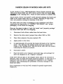
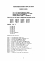
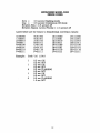
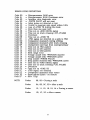
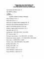
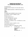
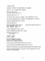
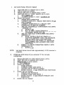
If the 34 pin ribbon cable has a twist (see fig. 1) at the end connector.
attach the first drive (C) to the end (twisted) connector. and the second
drive (D) to the inner connector. Configure both drives (C & 0) for drive
select 1 (DS 1). For a single drive installation. attach the drive to the end
(twisted) connector and configure as drive select 1 (OS 1).
-~4.
When installing a single drive. the resistor termination pack (RPI) must
remain installed. When installing two drives. the resistor tennination pack
(RP 1) must be removed from all but the last physical drive in the chain.
5.
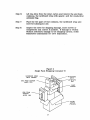
Slide the drive into your system's open slot with the activity LED towards
the outside of the system.
6.
Plug the 34 pin control cable and 20 pin data cable onto the hard drive's
printed circuit board edge connectors J 1 and J2 respectively. The striped
edge of the ribbon cable indicates pin 1. The location of pin 1 on the
connector must coincide with pin 1 on the printed circuit board edge
connector. Tip: On models 3650 and 3675 the striped edge of the ribbon
cable should always face the power connector (J3).
7.
Connect a 4 pin power connector to J3 on the hard disk.
8.
Check all connections for proper installation before powering up the
system. Do not apply power to the drive until the drive is secure and the
system cover is in place.
9.
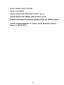
You are now ready to proceed with the required hard disk formatting
operations. To properly prepare the hard disk for use in your system. three
steps must be taken: low level format. partition. and high level or physical
format. Consult the formatting documentation supplied with the controller
card or partitioning software instructions for the model 3650 and 3675.
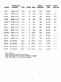
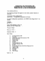
Drive Specifications
Drive
·CYL
HDS
RWC
Precomp
3650
3675
809
809
6
6
810
810
128
128
Technical Support is available at 1-800-356-5333.
7