1
Cisco 12000/10700 v3.1.1 Router Manager
User Guide
Software Release 3.1.1
Corporate Headquarters
Cisco Systems, Inc.
170 West Tasman Drive
San Jose, CA 95134-1706
USA
http://www.cisco.com
Tel: 408 526-4000
800 553-NETS (6387)
Fax: 408 526-4100
Text Part Number: OL-4455-01
THE SPECIFICATIONS AND INFORMATION REGARDING THE PRODUCTS IN THIS MANUAL ARE SUBJECT TO CHANGE WITHOUT NOTICE. ALL
STATEMENTS, INFORMATION, AND RECOMMENDATIONS IN THIS MANUAL ARE BELIEVED TO BE ACCURATE BUT ARE PRESENTED WITHOUT
WARRANTY OF ANY KIND, EXPRESS OR IMPLIED. USERS MUST TAKE FULL RESPONSIBILITY FOR THEIR APPLICATION OF ANY PRODUCTS.
THE SOFTWARE LICENSE AND LIMITED WARRANTY FOR THE ACCOMPANYING PRODUCT ARE SET FORTH IN THE INFORMATION PACKET THAT
SHIPPED WITH THE PRODUCT AND ARE INCORPORATED HEREIN BY THIS REFERENCE. IF YOU ARE UNABLE TO LOCATE THE SOFTWARE LICENSE
OR LIMITED WARRANTY, CONTACT YOUR CISCO REPRESENTATIVE FOR A COPY.
The Cisco implementation of TCP header compression is an adaptation of a program developed by the University of California, Berkeley (UCB) as part of UCB’s public
domain version of the UNIX operating system. All rights reserved. Copyright © 1981, Regents of the University of California.
NOTWITHSTANDING ANY OTHER WARRANTY HEREIN, ALL DOCUMENT FILES AND SOFTWARE OF THESE SUPPLIERS ARE PROVIDED “AS IS” WITH
ALL FAULTS. CISCO AND THE ABOVE-NAMED SUPPLIERS DISCLAIM ALL WARRANTIES, EXPRESSED OR IMPLIED, INCLUDING, WITHOUT
LIMITATION, THOSE OF MERCHANTABILITY, FITNESS FOR A PARTICULAR PURPOSE AND NONINFRINGEMENT OR ARISING FROM A COURSE OF
DEALING, USAGE, OR TRADE PRACTICE.
IN NO EVENT SHALL CISCO OR ITS SUPPLIERS BE LIABLE FOR ANY INDIRECT, SPECIAL, CONSEQUENTIAL, OR INCIDENTAL DAMAGES, INCLUDING,
WITHOUT LIMITATION, LOST PROFITS OR LOSS OR DAMAGE TO DATA ARISING OUT OF THE USE OR INABILITY TO USE THIS MANUAL, EVEN IF CISCO
OR ITS SUPPLIERS HAVE BEEN ADVISED OF THE POSSIBILITY OF SUCH DAMAGES.
CCIP, CCSP, the Cisco Arrow logo, the Cisco Powered Network mark, Cisco Unity, Follow Me Browsing, FormShare, and StackWise are trademarks of Cisco Systems, Inc.;
Changing the Way We Work, Live, Play, and Learn, and iQuick Study are service marks of Cisco Systems, Inc.; and Aironet, ASIST, BPX, Catalyst, CCDA, CCDP, CCIE, CCNA,
CCNP, Cisco, the Cisco Certified Internetwork Expert logo, Cisco IOS, the Cisco IOS logo, Cisco Press, Cisco Systems, Cisco Systems Capital, the Cisco Systems logo,
Empowering the Internet Generation, Enterprise/Solver, EtherChannel, EtherSwitch, Fast Step, GigaStack, Internet Quotient, IOS, IP/TV, iQ Expertise, the iQ logo, iQ Net
Readiness Scorecard, LightStream, MGX, MICA, the Networkers logo, Networking Academy, Network Registrar, Packet, PIX, Post-Routing, Pre-Routing, RateMUX, Registrar,
ScriptShare, SlideCast, SMARTnet, StrataView Plus, Stratm, SwitchProbe, TeleRouter, The Fastest Way to Increase Your Internet Quotient, TransPath, and VCO are registered
trademarks of Cisco Systems, Inc. and/or its affiliates in the U.S. and certain other countries.
All other trademarks mentioned in this document or Web site are the property of their respective owners. The use of the word partner does not imply a partnership relationship
between Cisco and any other company. (0304R)
Cisco 12000/10700 v3.1.1 Router Manager User Guide
Copyright © 2003 Cisco Systems, Inc. All rights reserved.
C O N T E N T S
About This Guide
xxv
Document Audience
xxv
Document Organization
xxvi
Conventions xxviii
Command Conventions xxviii
Example Conventions xxviii
Document Conventions xxix
Obtaining Documentation xxix
Cisco.com xxix
Documentation CD-ROM xxx
Ordering Documentation xxx
Documentation Feedback xxx
Obtaining Technical Assistance xxxi
Cisco.com xxxi
Technical Assistance Center xxxi
Cisco TAC Website xxxii
Cisco TAC Escalation Center xxxii
Obtaining Additional Publications and Information
CHAPTER
1
Overview
xxxii
1-1
Cisco Element Manager Framework (Cisco EMF) Software
Cisco 12000/10720 Router Manager Software
1-2
1-2
Key Features of the Cisco 12000/10720 Router Manager Software
Accessing Online Help
CHAPTER
2
Concepts
1-2
1-4
2-1
Cisco 12000/10720 Router Manager Objects and Interfaces
Physical Objects 2-2
Cisco 12000/10720 Router Chassis 2-3
Supporting Modules 2-5
Linecards 2-5
Physical Interfaces and Technologies 2-5
Logical Objects 2-6
Use of Telecom Graphics Objects 2-7
2-1
Cisco 12000/10700 v3.1.1 Router Manager User Guide
OL-4455-01
iii
Contents
OSI Mappings
2-10
Views 2-11
Component Managed View
Layer 3 QoS View 2-12
Network View 2-12
Physical View 2-12
VLAN View 2-12
2-11
Cisco 12000/10720 Router Manager Object States
Decommissioned State 2-14
Normal State 2-14
Errored 2-14
Performance Logging On 2-14
Lost Comms 2-15
Discovery Lost Comms 2-15
Mismatched 2-15
Transient Object States 2-15
CHAPTER
3
Getting Started
2-13
3-1
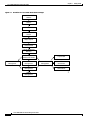
Cisco 12000/10720 Router Manager Workflow
3-1
Starting Cisco EMF and Cisco 12000/10720 Router Manager
Starting a Cisco EMF User Session 3-3
Launchpad 3-5
Launching an Application 3-5
Map Viewer (Viewer) 3-6
Groups 3-6
Access 3-6
Event Browser (Events) 3-6
Discovery 3-6
Notification Profiles 3-7
Thresholding Regimes 3-7
Event Groups 3-7
PreFilter 3-8
Quitting a Cisco EMF User Session 3-8
Deployment 3-8
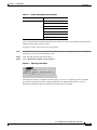
Deployment Process Outline 3-9
Manually Deploying a Generic Site Object 3-10
IP Auto Discovery of the Cisco Chassis 3-19
Manually Deploying a Cisco 12000/10720 Chassis
Commissioning and Subchassis Discovery 3-26
3-3
3-20
Cisco 12000/10700 v3.1.1 Router Manager User Guide
iv
OL-4455-01
Contents
Commissioning a Chassis 3-27
Decommissioning a Chassis 3-30
Object States 3-30
Manually Deploying Modules 3-30
User Named vs. Auto Named Module Deployment
Manually Deploying a GRP Card 3-31
Manually Deploying Line Cards 3-38
Manually Deploying Supporting Modules 3-50
Pre-deployment 3-58
Performing Pre-deployment 3-59
CHAPTER
4
Managing Chassis
3-31
4-1
Launching the Chassis Management Windows
4-2
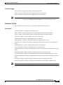
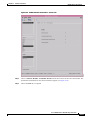
Management Information 4-3
Viewing the Management Information Window 4-3
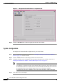
System Configuration 4-4
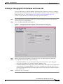
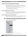
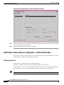
Entering or Changing IOS CLI Username and Passwords 4-5
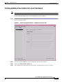
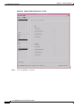
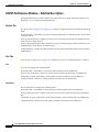
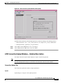
Management Information Window—Detailed Description 4-6
Configuration Tab 4-6
IOS/Command Line Security Tab 4-6
Chassis Configuration 4-7
Viewing the Chassis Configuration Window 4-7
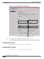
Commissioning a Chassis 4-8
Decommissioning a Chassis 4-8
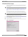
Starting Global Performance Logging 4-9
Stopping Global Performance Logging 4-10
Entering Additional Descriptions for a Selected Chassis 4-11
Device Management Tab in Configuration Window 4-12
Chassis Configuration Window—Detailed Description 4-13
Configuration Tab 4-13
Additional Descriptions Tab 4-14
Device Management Tab 4-14
SNMP Management 4-14
Viewing the SNMP Management Window 4-15
Modifying SNMP Community Names or Version 4-15
Enabling or Disabling Trap Generation 4-16
SNMP Management Window—Detailed Description 4-16
Community Names 4-16
Version 4-17
Cisco 12000/10700 v3.1.1 Router Manager User Guide
OL-4455-01
v
Contents
Trap Generation
4-17
Chassis Inventory 4-17
Viewing the Chassis Inventory Window 4-17
Chassis Inventory Window—Detailed Description
General Tab 4-18
Asset Tracking Tab 4-19
4-18
Chassis Fault Management 4-20
Viewing the Chassis Fault Management Window 4-20
Changing Column Width 4-24
Chassis Fault Management Window—Detailed Description
General Tab 4-25
Power Supply Tab 4-25
Temperature Tab 4-26
Fan Tab 4-26
Command Log 4-27
Viewing the Command Log Window 4-27
Command Log Window—Detailed Description
Command Log Details Tab 4-28
4-25
4-28
System Log 4-29
Viewing the SysLog Messages Window 4-29
System Log Window—Detailed Description 4-30
SysLog Message Tab 4-30
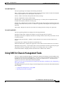
Using RME for Chassis Management Tasks 4-31
Configuration Backup/Restore Using RME 4-32
IOS Image Download Using RME 4-32
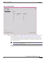
APS Status 4-32
Viewing the APS Status Window 4-32
APS Status Window—Detailed Description
APS Circuits Area 4-34
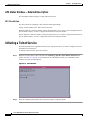
Initiating a Telnet Service
4-34
4-34
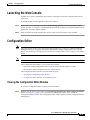
Launching the Web Console
4-35
Configuration Editor 4-35
Viewing the Configuration Editor Window 4-35
Downloading, Opening, or Editing the Running Configuration from a Selected Chassis
Searching in the Configuration Editor 4-37
Downloading the Edited Configuration File to a Selected Chassis 4-37
Configuration Editor Window—Detailed Description 4-37
Configuration Editor Tab 4-37
RPR Configuration
4-36
4-38
Cisco 12000/10700 v3.1.1 Router Manager User Guide
vi
OL-4455-01
Contents
Viewing the RPR Configuration Window 4-38
RPR Configuration Window—Detailed Description
Configuration Tab 4-39
Switch Over Tab 4-40
RPR Status 4-40
Viewing the RPR Status Window 4-40
RPR Status Window—Detailed Description
RP Status 4-41
LC Status 4-42
4-41
IP Routing Status 4-42
Viewing the IP Routing Status window 4-42
IP Routing Status Window—Detailed Description
Classless Inter-Domain Routing Tab 4-43
TCP Status 4-44
Viewing the TCP Status Window 4-45
TCP Status Window—Detailed Description
TCP Status Tab 4-46
TCP Connections Tab 4-47
UDP Status 4-48
Viewing the UDP Status Window 4-48
UDP Status Window—Detailed Description
Status 4-49
CHAPTER
5
Managing Modules
4-39
4-43
4-46
4-49
5-1
Cisco 12000/10720 Router Manager Module Names
Launching the Module Management Windows
5-1
5-2
Module Configuration 5-3
Viewing the Configuration Window 5-3
Commissioning a Selected Module 5-4
Decommissioning a Selected Module 5-5
Module Configuration Window—Detailed Description
Configuration Tab 5-7
5-7
Module Fault Management 5-7
Viewing the Module Fault Management Window 5-7
Module Fault Management Window—Detailed Description
Module Availability 5-8
Cisco Contact Details 5-9
Module Performance 5-9
Viewing the Module Performance Window
5-8
5-10
Cisco 12000/10700 v3.1.1 Router Manager User Guide
OL-4455-01
vii
Contents
Starting or Stopping Performance Logging 5-10
Module Performance Window—Detailed Description
CPU Usage 5-11
Performance Logging 5-11
Module Inventory 5-12
Viewing the Module Inventory Window 5-12
Module Inventory Window—Detailed Description
General 5-13
Asset Tracking 5-14
CHAPTER
6
Managing Interfaces
5-11
5-13
6-1
Cisco 12000/10720 Router Manager Interface Naming Conventions
CHAPTER
7
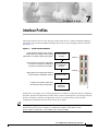
Interface Profiles
6-1
7-1
Interface Profile Types
7-2
Launching the Interface Profile Windows
7-2
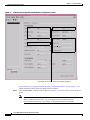
Creating an ATM Interface Profile 7-3
Editing an Existing ATM Interface Profile 7-6
Deleting an Existing ATM Interface Profile 7-6
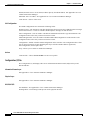
ATM Interface Configuration Profile Window—Detailed Description
Configuration (1) Tab 7-7
Configuration (2) Tab 7-8
7-7
Creating an HSRP Profile 7-9
Editing an Existing HSRP Interface Profile 7-10
Deleting an Existing HSRP Interface Profile 7-11
HSRP Profile Window—Detailed Description 7-11
HSRP Profile Parameters Area 7-11
Actions 7-12
Creating a POS Interface Profile 7-12
Editing an Existing POS Interface Profile 7-14
Deleting an Existing POS Interface Profile 7-15
POS Profile Window—Detailed Description 7-15
POS Config Tab 7-15
Creating a SRP Side Profile 7-17
Editing an Existing SRP Side Profile 7-19
Deleting an Existing SRP Side Profile 7-19
SRP Side Profile Window—Detailed Description
General Tab 7-20
Alarms Tab 7-21
7-20
Cisco 12000/10700 v3.1.1 Router Manager User Guide
viii
OL-4455-01
Contents
CHAPTER
8
Interface Configuration
8-1
Interfaces and Related Technology-Specific Windows
Launching the Interface Configuration Windows
8-1
8-2
Generic Interface Configuration 8-3
Viewing the Generic Interface Configuration Window 8-4
Configuring and Commissioning a Generic Interface 8-4
Decommissioning an Interface 8-5
Generic Interface Configuration Window—Detailed Description
Configuration Tab 8-5
ATM Interface Configuration 8-6
Viewing the ATM Interface Configuration Window 8-6
Configuring an ATM Interface 8-7
ATM Interface Configuration Window—Detailed Description
Configuration (1) Tab 8-8
Configuration (2) Tab 8-9
8-5
8-8
Ethernet Interface Configuration 8-9
Viewing the Ethernet Interface Configuration Window 8-10
Configuring an Ethernet Interface 8-11
Ethernet Interface Configuration Window—Detailed Description
Configuration Tab 8-12
HSRP Parameters Tab 8-12
IP Configuration 8-13
Viewing the IP Configuration Window 8-14
Configuring an IP Interface 8-14
IP Configuration Window—Detailed Description
Generic Parameters Tab 8-15
8-15
POS Interface Configuration 8-15
Viewing the POS Interface Configuration Window 8-15
Configuring a POS Interface 8-16
POS Interface Configuration Window—Detailed Description
POS Config Tab 8-17
APS Interface Configuration 8-18
Viewing the APS Configuration Window 8-19
Adding a Working Interface 8-20
Removing a Working Interface 8-20
Adding a Protected Interface 8-20
Removing a Protected Interface 8-20
APS Configuration Window—Detailed Description
APS Tab 8-21
8-12
8-17
8-21
Cisco 12000/10700 v3.1.1 Router Manager User Guide
OL-4455-01
ix
Contents
APS Interface
8-21
SRP Interface Configuration 8-22
Viewing the SRP Interface Configuration Attributes 8-22
Configuring a SRP Interface 8-23
SRP Interface Configuration Window—Detailed Description
General 8-23
IPS 8-23
8-23
SRP Interface Side Configuration 8-24
Viewing the SRP Interface Side Configuration Attributes 8-24
Configuring a SRP Side 8-25
SRP Interface Side Configuration Window—Detailed Description
General Tab 8-26
Alarms Tab 8-27
CHAPTER
9
Interface Status
8-26
9-1
Interfaces and Related Technology-Specific Windows
Launching the Interface Status Windows
9-1
9-2
Generic Interface Status 9-3
Viewing the Generic Interface Status Window 9-3
Generic Interface Status Window—Detailed Description
Interface Details 9-4
Last Change Details 9-4
Transmission Details 9-4
ATM Interface Status 9-5
Viewing the ATM Interface Status Window 9-5
ATM Interface Status Window—Detailed Description
ATM Transmit Status 9-6
ATM Receive Status 9-7
Physical Layer Status 9-7
ATM Port Status 9-7
Action 9-7
ATM Interface Faults 9-8
Viewing the ATM Interface Faults Window 9-8
ATM Interface Faults Window—Detailed Description
Fault Tab 9-9
DS3/E3 Interface Status 9-9
Viewing the DS3/E3 Interface Status Window 9-9
DS3/E3 Interface Status Window—Detailed Description
Status Tab 9-10
9-4
9-6
9-9
9-10
Cisco 12000/10700 v3.1.1 Router Manager User Guide
x
OL-4455-01
Contents
SONET Interface Status 9-12
Viewing the SONET Interface Status Window 9-12
SONET Status Window—Detailed Description 9-16
Medium 9-16
Section 9-16
Line 9-16
Path 9-16
Virtual Tributary 9-17
SRP Interface Status 9-17
Viewing the SRP Interface Status Attributes 9-17
SRP Interface Status Window—Detailed Description
Interface Tab 9-18
Side A Frame 9-18
Side B Frame 9-18
SRP Side IPS Status 9-19
Viewing the IPS Status Attributes 9-19
IPS Status Window—Detailed Description
IPS Status 9-20
Remote Node 9-20
SRP Topology Map 9-20
Viewing the SRP Topology Map 9-20
SRP Topology Map—Detailed Description
Topology Map 9-21
CHAPTER
10
Interface Performance
9-18
9-20
9-21
10-1
Interfaces and Related Technology-Specific Windows
Launching the Interface Performance Windows
10-1
10-2
Generic Interface Performance 10-3
Viewing the Generic Interface Performance Window 10-3
Starting Performance Logging for a Selected Interface 10-5
Stopping Performance Logging for a Selected Interface 10-7
Generic Interface Performance Window—Detailed Description
Performance (1) Tab 10-8
Performance (2) Tab 10-9
Performance (3) Tab 10-10
10-8
SONET Interface Performance 10-10
Viewing the SONET Interface Performance Window 10-10
SONET Performance Window—Detailed Description 10-14
Section Tab 10-14
Cisco 12000/10700 v3.1.1 Router Manager User Guide
OL-4455-01
xi
Contents
Line Tab 10-14
Path Tab 10-15
Virtual Tributary Tab
10-15
DS3/E3 Interface Performance 10-15
Viewing the DS3/E3 Interface Performance Window 10-15
DS3/E3 Interface Performance Window—Detailed Description
DS3 Performance Tab 10-17
E3 Performance Tab 10-18
Ethernet Interface Performance 10-19
Viewing the Ethernet Interface Performance Window 10-19
Ethernet Interface Performance Window—Detailed Description
General Statistics 10-20
Collision Statistics 10-20
SRP Performance 10-21
Viewing the SRP Performance Window 10-21
SRP Performance Window—Detailed Description
Interface Tab 10-25
Outer Ring Tab 10-26
Inner Ring Tab 10-27
Side Tab 10-28
11
Layer 3 QoS
10-20
10-24
SRP Side Performance 10-28
Viewing the SRP Side Performance Window 10-29
SRP Side Performance Window—Detailed Description
Ring Tab 10-31
Host Tab 10-32
Errors Tab 10-33
CHAPTER
10-17
10-31
11-1
Launching the Layer 3 QoS Windows
11-1
CAR and WRED Overview 11-3
Access Lists 11-3
Committed Access Rate (CAR) 11-3
Weighted Random Early Detection (WRED) 11-3
Towards the Fabric (ToFab) 11-4
MDRR Overview 11-4
MDRR in Cisco 12000/10720 Router Manager 11-4
Implications of Engine Type 11-5
CAR and WRED in Cisco 12000/10720 Router Manager
The Workflow for CAR
11-5
11-6
Cisco 12000/10700 v3.1.1 Router Manager User Guide
xii
OL-4455-01
Contents
CAR Policy Configuration 11-6
Per Interface Rate Control (PIRC) Support 11-6
Limited Support for Engine 4 11-7
Creating a CAR Policy 11-7
Applying an Access List to a CAR Policy 11-8
CAR Policy Configuration Window—Detailed Description
CAR Policy Configuration Tab 11-9
Exceed Action 11-10
Access List Configuration 11-10
Creating Access Lists 11-10
Access List Configuration Window—Detailed Description
General Tab 11-12
IP Standard Tab 11-13
IP Precedence Tab 11-14
MAC 11-15
IP Extended Tab 11-16
CAR Policy Apply 11-18
Applying a CAR Policy to an Interface 11-18
Removing a CAR Policy from an Interface 11-19
Editing or Deleting a CAR Policy 11-19
CAR Policy Apply Window—Detailed Description
CAR Policy Apply Tab 11-20
CAR Policy Status 11-21
Viewing the CAR Policy Status Window
11-9
11-12
11-20
11-21
The Workflow for WRED/DRR 11-22
Engine Type Support for WRED 11-22
CoS Queue Group Configuration 11-23
Creating a CoS Queue Group Under WRED 11-23
Editing an Existing CoS Queue Group 11-24
Deleting an Existing CoS Queue Group 11-24
CoS Queue Group Configuration Window—Detailed Description
CoS Queue Group Tab 11-25
DRR Tab 11-27
WRED Tx Configuration 11-28
Applying a CoS Queue Group to an Interface 11-28
Removing a CoS Queue Group from an Interface 11-30
Changing the Association of a CoS Queue Group 11-30
WRED Tx Configuration Window—Detailed Description
Tx Config Tab 11-31
11-25
11-31
Cisco 12000/10700 v3.1.1 Router Manager User Guide
OL-4455-01
xiii
Contents
WRED ToFab Configuration 11-32
Creating a ToFab Policy 11-32
Editing an Existing ToFab policy 11-33
Deleting an Existing ToFab policy 11-34
WRED ToFab Policy Configuration Window—Detailed Description
ToFab Policy Configuration tab 11-35
Slot Table Parameters 11-35
Actions 11-35
Slot-CosQ Groups 11-35
WRED Rx Configuration 11-36
Associating a ToFab Policy to a Line card 11-36
Disassociating a ToFab Policy from a Line card 11-37
Changing the Association of a ToFab Policy 11-37
WRED Rx Configuration Window—Detailed Description
Rx Configuration Tab 11-38
Actions 11-38
Associated slot—Table Info 11-38
Apply Status 11-38
CHAPTER
12
Managing ATM Connections
11-35
11-38
12-1
ATM Connections Supported by Cisco 12000/10720 Router Manager
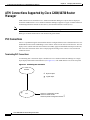
PVC Connections 12-2
Terminating PVC Connections 12-2
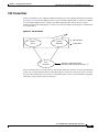
SVC Connections 12-3
Launching the ATM Connections Windows
12-2
12-4
ATM Connection Synchronization 12-4
Device_is_Master (default policy) 12-5
Normal Policy 12-6
CEMF_is_Master_After_First_Sync 12-6
Creating ATM Connections
12-7
Uploading Existing ATM Connections and QoS Profiles 12-7
Naming Convention for the Uploaded Connection Objects 12-8
Configuring the Management Password Information 12-8
Without configuring the Management Password Information 12-8
Viewing the ATM Connection Upload Window 12-9
Uploading Existing ATM Connections and ATM QoS Profiles 12-10
ATM Connection Upload Window—Detailed Description 12-11
Connection Upload Tab 12-11
Managing ATM QoS Profiles
12-12
Cisco 12000/10700 v3.1.1 Router Manager User Guide
xiv
OL-4455-01
Contents
Creating ATM QoS Profiles 12-12
Editing an ATM QoS Profile 12-14
Deleting an ATM QoS Profile 12-15
ATM QoS Profiles Configuration Window—Detailed Description
Profile Tab 12-17
RxTx Parameters Tab 12-17
12-17
Deploying ATM Connection Objects 12-18
Deploying a PVC Object 12-18
Deploying an SVC Object 12-22
Applying an ATM QoS Profile to an ATM Connection
12-28
ATM PVC Configuration 12-30
Viewing the ATM VCL Configuration Window 12-30
Connecting or Disconnecting a PVC 12-31
Decommissioning or Re-Commissioning a PVC 12-32
ATM OAM Ping 12-32
ATM VCL Configuration Window—Detailed Description
Configuration Tab 12-34
Layer 3 Configuration Tab 12-35
OAM Ping Tab 12-36
12-34
SVC Configuration 12-37
Viewing the SVC Configuration Window 12-37
Connecting or Disconnecting an SVC 12-38
Decommissioning or Recommissioning an SVC 12-38
SVC Configuration Window—Detailed Description 12-38
Configuration 12-38
PVC Status 12-40
ATM VCL Status Window—Detailed Description
Status tab 12-41
OAM tab 12-42
CHAPTER
13
Managing VLANs
12-41
13-1
Launching the VLAN Windows
VLAN Synchronization
13-1
13-2
Deploying VLAN objects 13-4
Deploying a Domain 13-4
Deploying a VLAN and a Sub-Interface Object Under an Existing Domain
VLAN Configuration 13-14
Viewing the VLAN Configuration Window
Commissioning a VLAN 13-15
13-7
13-14
Cisco 12000/10700 v3.1.1 Router Manager User Guide
OL-4455-01
xv
Contents
Decommissioning a VLAN 13-16
Start Performance Logging 13-17
Stop Performance Logging 13-18
VLAN Configuration Window—Detailed Description
Configuration Tab 13-19
VLAN Performance 13-19
Viewing the VLAN Performance Window 13-20
VLAN Performance Window—Detailed Description
Reparenting VLANs and VLAN Sub-Interfaces
Deleting VLAN Objects
CHAPTER
14
Routing
13-19
13-21
13-21
13-22
14-1
Launching the Routing Windows
BGP Management
14-1
14-2
BGP Configuration 14-3
Viewing the BGP Details Tab on the BGP Configuration Window 14-3
BGP Details Tab—Detailed Description 14-4
BGP General 14-4
BGP Information 14-5
Enabling BGP on a Chassis 14-5
Enable BGP Window—Detailed Description 14-6
Action 14-6
Modifying BGP on a Chassis 14-7
BGP Modify Window—Detailed Description 14-8
Disabling BGP on a Chassis 14-8
Viewing the Network Tab on the BGP Configuration Window 14-9
Network Tab—Detailed Description 14-10
BGP Network Information 14-10
BGP Network Configuration 14-11
BGP Network Configuration Window—Detailed Description 14-11
Action 14-12
Viewing the Neighbor Tab on the BGP Configuration Window 14-12
Neighbor Tab—Detailed Description 14-13
BGP Neighbor Information 14-13
BGP Neighbor Configuration 14-13
BGP Neighbor Configuration Window—Detailed Description 14-14
Action 14-15
Viewing the Redistribution Tab on the BGP Configuration Window 14-15
Redistribution Tab—Detailed Description 14-16
Cisco 12000/10700 v3.1.1 Router Manager User Guide
xvi
OL-4455-01
Contents
BGP Redistribution Information 14-16
BGP Redistribute Configuration 14-16
BGP Redistribute Configuration—Detailed Description
Action 14-17
BGP Status 14-18
Viewing the BGP Status Window 14-18
BGP Status Window—Detailed Description
BGP-Details 14-21
Network 14-22
Neighbor 14-22
Redistribution 14-23
14-17
14-21
BGP Address-Family Synchronization 14-23
BGP Address-Family Synchronization—Detailed Description
Synchronization Tab 14-26
14-26
BGP Address Family Configuration 14-26
Viewing the AF-General Tab on the BGP Address-Family Configuration Window 14-27
AF-General Tab—Detailed Description 14-28
BGP General 14-28
BGP Address Family Information 14-28
Configuring Address Family 14-28
Configure Address Family—Detailed Description 14-29
Add Address Family 14-29
Modifying BGP Address Family 14-30
BGP Address Family-Modify Address Family Parameters—Detailed Description 14-31
Modify Address Family Parameters 14-31
Viewing the AF-Network Tab on the BGP Address-Family Configuration Window 14-32
AF-Network Tab—Detailed Description 14-33
Network Information 14-33
BGP Address Family—Network Configuration 14-33
BGP Address Family-Network Configuration—Detailed Description 14-34
Add/Remove Network 14-34
Viewing the AF-Neighbor Tab on the BGP Address-Family Configuration Window 14-35
AF-Neighbor Tab—Detailed Description 14-36
Neighbor Information 14-36
BGP Address Family—Neighbor Configuration 14-36
BGP Address Family-Neighbor Configuration—Detailed Description 14-37
Add/Remove Neighbor 14-37
Viewing the AF-Redistribute Tab on the BGP Address-Family Configuration Window 14-38
AF-Redistribute Tab—Detailed Description 14-39
Cisco 12000/10700 v3.1.1 Router Manager User Guide
OL-4455-01
xvii
Contents
Redistribute Information 14-39
BGP Address Family—Redistribute Configuration 14-40
BGP Address Family-Configure Redistribute Protocol—Detailed Description
Add/Remove Redistribution Information 14-41
BGP Address-Family Status 14-41
Viewing the BGP Address-Family Status window 14-41
BGP Address-Family Status Window—Detailed Description
AF-General 14-45
AF-Network 14-46
AF-Neighbor 14-46
AF-Redistribute 14-46
OSPF Management
14-41
14-45
14-47
OSPF Configuration 14-47
Viewing the OSPF Configuration Window 14-47
Config Tab—Detailed Description 14-48
Config 14-48
Adding an OSPF Process 14-49
Removing an OSPF Process 14-50
Viewing the Network Tab on the OSPF Configuration Window
Network Tab—Detailed Description 14-51
Ospf Network 14-51
Configuring a Network 14-52
Configure Network—Detailed Description 14-54
Configure Network 14-54
14-51
OSPF Status 14-54
Viewing the OSPF Status Window 14-54
OSPF Status—Detailed Description 14-61
General Group 14-61
Process Information 14-62
Area 14-62
Interface 14-63
Neighbor 14-65
Link State 14-66
Host 14-66
CHAPTER
15
MPLS Management
Introduction
15-1
15-1
MPLS Management Workflow
15-2
Launching the MPLS Management Windows
15-3
Cisco 12000/10700 v3.1.1 Router Manager User Guide
xviii
OL-4455-01
Contents
MPLS Forwarding Information 15-4
Viewing the MPLS Forwarding Information Window 15-4
MPLS Forwarding Information Window—Detailed Description
MPLS Forwarding Information Tab 15-5
15-5
Fault Management for MPLS LSR Interfaces 15-6
MPLS Interface Status 15-6
Viewing the MPLS Interface Status Window 15-6
MPLS Interface Status Window—Detailed Description 15-7
MPLS Interface Information 15-8
Viewing the MPLS Interface Information Window 15-8
MPLS Interface Information Window—Detailed Description 15-9
Performance Management for MPLS LSR Interfaces 15-14
MPLS Interface Performance 15-14
Viewing the MPLS Interface Performance Window 15-14
MPLS Interface Performance Window—Detailed Description
15-15
Fault Management for MPLS LDP 15-18
MPLS LDP Entity Status Window 15-18
Viewing the MPLS LDP Entity Status Window 15-18
MPLS LDP Entity Status Window—Detailed Description 15-19
MPLS LDP Hello Adjacencies 15-26
Viewing the MPLS LDP Hello Adjacencies Window 15-26
MPLS LDP Hello Adjacencies Window—Detailed Description 15-27
MPLS LDP Peer Status 15-28
Viewing the MPLS LDP Peer Status Window 15-28
MPLS LDP Peer Status Window—Detailed Description 15-29
Fault Management for MPLS Traffic Engineering 15-33
MPLS Tunnel Information 15-33
Viewing the MPLS Tunnel Information Window 15-33
MPLS Tunnel Information Window—Detailed Description
CHAPTER
16
MPLS VRF Management
15-34
16-1
Introduction to VRF Management
VRF Management Workflows
16-1
16-2
Launching the MPLS VRF Management Windows
16-2
Creating VRF Objects in the EM 16-3
Deploying VRF Objects 16-3
Creating and Configuring the VRF Policy on a Device 16-8
Configuring and Creating a VRF Policy on a Selected Chassis
Removing a VRF Policy from a Selected Chassis 16-10
16-8
Cisco 12000/10700 v3.1.1 Router Manager User Guide
OL-4455-01
xix
Contents
Adding a Routing Target to a Selected Chassis 16-10
Deleting a Routing Target from a Selected Chassis 16-10
VRF Configuration Window—Detailed Description 16-11
VRF Configuration Tab 16-11
Associating a VRF Policy with an Interface 16-12
Associating VRF Policies 16-13
Removing a VRF Policy from a Selected Interface
VRF Association Window—Detailed Description
VRF Tab 16-14
16-14
16-14
VRF Fault Management 16-15
VRF Status 16-15
Viewing the VRF Status Window 16-15
VRF Status Window—Detailed Description 16-16
General Tab 16-16
Performance and Security Tab 16-17
Interface VRF Status 16-19
Viewing the Interface VRF Status Window 16-19
Interface VRF Status Window—Detailed Description 16-20
Interface VRF Association Tab 16-20
VPN Status 16-20
Viewing the VPN Status Window 16-20
VPN Status Window—Detailed Description 16-21
General Tab 16-21
Routes Tab 16-22
Route Targets Tab 16-23
BGP Neighbor Tab 16-25
VRF Object Status 16-26
Viewing the VRF Object Status Window 16-26
VRF Object Status Window—Detailed Description 16-27
General Tab 16-27
Routes Tab 16-28
Route Targets Tab 16-29
Interface Association Tab 16-31
Performance Tab 16-32
Cisco 12000/10700 v3.1.1 Router Manager User Guide
xx
OL-4455-01
Contents
CHAPTER
17
MPLS Trap Management
17-1
MPLS Traps Supported by the C12000/10720 Router Manager
17-1
Enabling/Disabling Traps on the Device 17-3
MPLS Trap Configuration Window—Detailed Description
Traps Tab 17-4
17-4
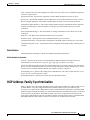
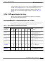
MPLS CLI Troubleshooting Services 17-5
Launching the MPLS CLI Troubleshooting Services Windows
Verify Routing Protocols 17-6
Verify Routing Tables 17-7
Verify CEF Switching 17-8
Verify CEF Switching Summary 17-9
Verify MPLS Interfaces 17-10
Verify Label Distribution 17-11
Verify Label Bindings 17-12
Verify Interface CEF Switching 17-13
CHAPTER
18
Fault Management
17-5
18-1
Cisco 12000/10720 Router Manager Alarms
Viewing Alarms 18-2
18-1
Cisco 12000/10720 Router Trap Support 18-2
Chassis Alarms 18-3
Interface Alarms 18-5
Syslog Traps 18-5
Configuration Management Traps 18-6
Heartbeat Polling 18-7
Connectivity Management 18-7
Operational Status Polling 18-7
Disabling Heartbeat Polling 18-7
Performance Logging 18-8
CHAPTER
19
Change Management
19-1
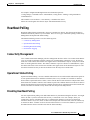
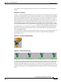
Inserting a Line Card
Mismatched State
19-2
19-2
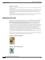
Removing a Line Card
CHAPTER
20
19-4
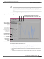
Performance Management and Historical Data
20-1
Performance Information Available Using Cisco 12000/10720 Router Manager
Viewing the Performance Manager Window
20-2
20-2
Cisco 12000/10700 v3.1.1 Router Manager User Guide
OL-4455-01
xxi
Contents
Viewing Performance Statistics 20-4
Viewing a Chart 20-5
Printing a Performance File 20-6
Saving Performance Data to a File 20-6
Archiving 20-6
Exporting A Performance File 20-7
Performance Manager Window—Detailed Description
Monitored Attributes 20-7
Time Period 20-8
Summary 20-8
Refresh 20-9
Line Chart Tab 20-9
Table Display Tab 20-9
CHAPTER
21
Troubleshooting and FAQs
21-1
Administration 21-1
What Version is the Software? 21-1
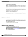
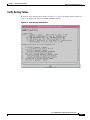
What Dialogs Use the IOS CLI Instead of SNMP?
Configuration 21-3
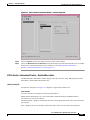
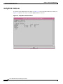
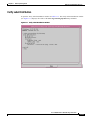
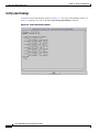
Verifying SNMP, Log, and Trap Settings 21-3
BGP Configuration 21-5
ATM Sub-Interface Configuration 21-5
ATM IP Configuration GUI Display ERROR Settings
Viewing ATM Physical Port Configurations? 21-6
APPENDIX
A
SONET/SDH Conversion Chart
APPENDIX
B
GUI Synchronization Details
21-2
21-5
A-1
B-1
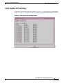
GUIs that Synchronize with the Device when Launched
B-1
GUIs that do not Synchronize with the Device when Launched
APPENDIX
C
20-7
B-2
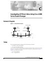
Investigating LSP Black Holes Using Cisco 12000 Series Router Manager
Network Diagram
C-1
C-1
Setup C-1
Problem C-2
Analysis of Problem
Solution C-3
C-2
Cisco 12000/10700 v3.1.1 Router Manager User Guide
xxii
OL-4455-01
Contents
Running Configs
CE1 C-4
PE1 C-5
P C-7
PE2 C-11
CE2 C-12
C-4
INDEX
Cisco 12000/10700 v3.1.1 Router Manager User Guide
OL-4455-01
xxiii
Contents
Cisco 12000/10700 v3.1.1 Router Manager User Guide
xxiv
OL-4455-01
About This Guide
This guide provides information on using the Cisco 12000/10720 Router Manager application. The
Cisco 12000/10720 Router Manager uses the Cisco Element Management Framework (Cisco EMF),
which provides element management to simplify the day-to-day tasks of an operator. These tasks can
include equipment provisioning, fault monitoring, interface configuration, and gathering and displaying
interface performance statistics.
This chapter contains the following sections:
•
Document Audience
•
Document Organization
•
Conventions
•
Obtaining Documentation
•
Obtaining Technical Assistance
Document Audience
This user guide is written as a technical resource for network managers, system administrators, network
analysts, and system operators, with the following qualifications:
•
Basic understanding of network design, operation, and terminology
•
Familiarity with your own network configurations
•
Basic familiarity with UNIX
•
Familiarity with the Cisco Element Management Framework Installation and Administration Guide
and Cisco Element Management Framework User Guide.
Cisco 12000/10700 v3.1.1 Router Manager User Guide
OL-4455-01
xxv
About This Guide
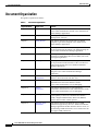
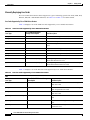
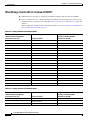
Document Organization
Document Organization
This guide is organized as follows:
Table 1
Document Organization
Chapter Number
Chapter Title
Content
Chapter 1
Overview
This chapter provides a basic overview of the
Cisco 12000/10720 Routers and the Cisco 12000/10720
Router Manager application.
Chapter 2
Concepts
This chapter describes Cisco 12000/10720 Router
Manager basic concepts.
Chapter 3
Getting Started
This chapter describes the typical tasks you should
complete to get started using the Cisco 12000/10720
Router Manager application.
Chapter 4
Managing Chassis
This chapter describes the various management tasks that
can be performed on the chassis to be managed using the
Cisco 12000/10720 Router Manager application.
Chapter 5
Managing Modules
This chapter describes the management functions
available on Gigabit Route Processors (GRPs), line cards,
and supporting modules.
Chapter 6
Managing Interfaces
This chapter describes the various management tasks that
can be performed on the interfaces of the Cisco devices
being managed using the Cisco 12000/10720 Router
Manager application.
Chapter 7
Interface Profiles
This chapter describes how to create interface profiles
using the Cisco 12000/10720 Router Manager
application.
Chapter 8
Interface
Configuration
This chapter describes how to configure or set up
interfaces associated with each line card.
Chapter 9
Interface Status
This chapter describes how to view appropriate status
information for each of the interfaces on the
Cisco 12000/10720 Routers you are managing.
Chapter 10
Interface
Performance
This chapter describes how to view appropriate
performance information for each of the interfaces on the
Cisco 12000/10720 Routers you are managing.
Chapter 11
Layer 3 QoS
This chapter describes how to create and configure Layer
3 QoS (Quality of Service) Committed Access Rate
(CAR), Weighted Random Early Detection (WRED)
policies and To-Fabric (ToFab) policies.
Chapter 12
Managing ATM
Connections
This chapter describes the different types of ATM
connections supported by the Cisco 12000/10720 Router
Manager application and then describes how to create, set
up and manage ATM connections. Cisco 10720 routers do
not support ATM connections.
Cisco 12000/10700 v3.1.1 Router Manager User Guide
xxvi
OL-4455-01
About This Guide
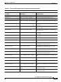
Document Organization
Table 1
Document Organization (continued)
Chapter Number
Chapter Title
Content
Chapter 13
Managing VLANs
This chapter describes the VLAN functionality supported
by the Cisco 12000/10720 Router Manager application
and guides you through the process of creating and
configuring VLAN objects.
Chapter 14
Routing
This chapter describes the Border Gateway Protocol
(BGP) and the Open Shortest Path First Routing Protocol
(OSPF).
Chapter 15
MPLS Management
This chapter describes the Multi Protocol Label
Switching (MPLS) management tasks that can be
performed using the Cisco 12000/10720 Router Manager
application.
Chapter 16
MPLS VRF
Management
This chapter describes the various MPLS VRF
Management tasks that can be performed using the
Cisco 12000/10720 Manager (C12k/10720M)
application.
Chapter 17
MPLS Trap
Management
This chapter describes MPLS traps that can be configured
using the Cisco 12000/10720 Router Manager application
using the MPLS Trap Configuration window.
Chapter 18
Fault Management
This chapter describes how to view appropriate fault
information on the Cisco 12000/10720 Routers you are
managing.
Chapter 19
Change Management
This chapter describes how to manage the insertion and
removal of linecards from the Cisco 12000/10720 Routers
being managed.
Chapter 20
Performance
Management and
Historical Data
This chapter describes the Performance Manager
application. Performance Manager displays historical
data as well as current data in the form of a line chart, bar
chart, or table. Performance logging can be enabled on
multiple or individual object basis.
Chapter 21
Troubleshooting and
FAQs
Details answers to some commonly asked questions or
problems.
Appendix A
SONET/SDH
Conversion Chart
This appendix details Synchronous Optical Network
(SONET) and Synchronous Digital Hierarchy (SDH)
conversion information.
Appendix B
GUI Synchronization List the GUIs that synchronize with the device when
Details
launched, and those GUIs that do not synchronize with
the device when launched.
Appendix C
Investigating LSP
Black Holes Using
Cisco 12000 Series
Router Manager
Gives an example of a problem, and details the solution.
Cisco 12000/10700 v3.1.1 Router Manager User Guide
OL-4455-01
xxvii
About This Guide
Conventions
Conventions
Conventions are presented in the following sections:
•
Command Conventions
•
Example Conventions
•
Document Conventions
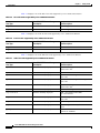
Command Conventions
Commands use these conventions:
Table 2
Command Conventions
Format
Description
Example
Boldface font
Commands, keywords, and user entries in text
/usr/bin
Italic font
Arguments for which users supply values
CEMF_ROOT
Square brackets ([ ])
Optional keywords or arguments
[?]
Braces ({ })
Alternative but required keywords
{yes | no}
Vertical bar (|)
Separator between alternative but required keywords {yes | no}
Angle brackets (<>)
Non-printing user entries (such as passwords)
<rootpassword>
Example Conventions
Examples use these conventions:
Table 3
Example Conventions
Format
Plain screen
Bold screen
font
font
Italic screen
font
Square brackets ([ ])
Description
Example
Onscreen displays, examples, and scripts
C12ooo/C10700 EM
User entries in examples and scripts
./cemf install
User entry variables
remote-host
Default responses
[tftp idle]
Cisco 12000/10700 v3.1.1 Router Manager User Guide
xxviii
OL-4455-01
About This Guide
Obtaining Documentation
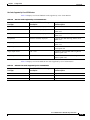
Document Conventions
This guide uses these conventions:
Table 4
Document Conventions
Format
Description
Example
Boldface font
Menu options, button names, and names of keys on
keyboards
Exit
Italic font
Directories, filenames, and titles
Cisco Element
Management
Framework User
Guide Release 3.2
(78-12536-01)
Notes and cautionary statements use these conventions:
Note
Caution
Means reader take note. Notes contain helpful suggestions or references to materials not
contained in this manual.
Means reader be careful. You are capable of doing something that might result in equipment
damage or loss of data.
Obtaining Documentation
Cisco provides several ways to obtain documentation, technical assistance, and other technical
resources. These sections explain how to obtain technical information from Cisco Systems.
Cisco.com
You can access the most current Cisco documentation on the World Wide Web at this URL:
http://www.cisco.com/univercd/home/home.htm
You can access the Cisco website at this URL:
http://www.cisco.com
International Cisco websites can be accessed from this URL:
http://www.cisco.com/public/countries_languages.shtml
Cisco 12000/10700 v3.1.1 Router Manager User Guide
OL-4455-01
xxix
About This Guide
Obtaining Documentation
Documentation CD-ROM
Cisco documentation and additional literature are available in a Cisco Documentation CD-ROM
package, which may have shipped with your product. The Documentation CD-ROM is updated regularly
and may be more current than printed documentation. The CD-ROM package is available as a single unit
or through an annual or quarterly subscription.
Registered Cisco.com users can order a single Documentation CD-ROM (product number
DOC-CONDOCCD=) through the Cisco Ordering tool:
http://www.cisco.com/en/US/partner/ordering/ordering_place_order_ordering_tool_launch.html
All users can order monthly or quarterly subscriptions through the online Subscription Store:
http://www.cisco.com/go/subscription
Ordering Documentation
You can find instructions for ordering documentation at this URL:
http://www.cisco.com/univercd/cc/td/doc/es_inpck/pdi.htm
You can order Cisco documentation in these ways:
•
Registered Cisco.com users (Cisco direct customers) can order Cisco product documentation from
the Networking Products MarketPlace:
http://www.cisco.com/en/US/partner/ordering/index.shtml
•
Nonregistered Cisco.com users can order documentation through a local account representative by
calling Cisco Systems Corporate Headquarters (California, U.S.A.) at 408 526-7208 or, elsewhere
in North America, by calling 800 553-NETS (6387).
Documentation Feedback
You can submit comments electronically on Cisco.com. On the Cisco Documentation home page, click
Feedback at the top of the page.
You can e-mail your comments to [email protected].
You can submit comments by using the response card (if present) behind the front cover of your
document or by writing to the following address:
Cisco Systems
Attn: Customer Document Ordering
170 West Tasman Drive
San Jose, CA 95134-9883
We appreciate your comments.
Cisco 12000/10700 v3.1.1 Router Manager User Guide
xxx
OL-4455-01
About This Guide
Obtaining Technical Assistance
Obtaining Technical Assistance
Cisco provides Cisco.com, which includes the Cisco Technical Assistance Center (TAC) website, as a
starting point for all technical assistance. Customers and partners can obtain online documentation,
troubleshooting tips, and sample configurations from the Cisco TAC website. Cisco.com registered users
have complete access to the technical support resources on the Cisco TAC website, including TAC tools
and utilities.
Cisco.com
Cisco.com offers a suite of interactive, networked services that let you access Cisco information,
networking solutions, services, programs, and resources at any time, from anywhere in the world.
Cisco.com provides a broad range of features and services to help you with these tasks:
•
Streamline business processes and improve productivity
•
Resolve technical issues with online support
•
Download and test software packages
•
Order Cisco learning materials and merchandise
•
Register for online skill assessment, training, and certification programs
To obtain customized information and service, you can self-register on Cisco.com at this URL:
http://tools.cisco.com/RPF/register/register.do
Technical Assistance Center
The Cisco TAC is available to all customers who need technical assistance with a Cisco product,
technology, or solution. Two types of support are available: the Cisco TAC website and the Cisco TAC
Escalation Center. The type of support that you choose depends on the priority of the problem and the
conditions stated in service contracts, when applicable.
We categorize Cisco TAC inquiries according to urgency:
•
Priority level 4 (P4)—You need information or assistance concerning Cisco product capabilities,
product installation, or basic product configuration. There is little or no impact to your business
operations.
•
Priority level 3 (P3)—Operational performance of the network is impaired, but most business
operations remain functional. You and Cisco are willing to commit resources during normal business
hours to restore service to satisfactory levels.
•
Priority level 2 (P2)—Operation of an existing network is severely degraded, or significant aspects
of your business operations are negatively impacted by inadequate performance of Cisco products.
You and Cisco will commit full-time resources during normal business hours to resolve the situation.
•
Priority level 1 (P1)—An existing network is “down,” or there is a critical impact to your business
operations. You and Cisco will commit all necessary resources around the clock to resolve the
situation.
Cisco 12000/10700 v3.1.1 Router Manager User Guide
OL-4455-01
xxxi
About This Guide
Obtaining Additional Publications and Information
Cisco TAC Website
The Cisco TAC website provides online documents and tools to help troubleshoot and resolve technical
issues with Cisco products and technologies. To access the Cisco TAC website, go to this URL:
http://www.cisco.com/tac
All customers, partners, and resellers who have a valid Cisco service contract have complete access to
the technical support resources on the Cisco TAC website. Some services on the Cisco TAC website
require a Cisco.com login ID and password. If you have a valid service contract but do not have a login
ID or password, go to this URL to register:
http://tools.cisco.com/RPF/register/register.do
If you are a Cisco.com registered user, and you cannot resolve your technical issues by using the Cisco
TAC website, you can open a case online at this URL:
http://www.cisco.com/tac/caseopen
If you have Internet access, we recommend that you open P3 and P4 cases online so that you can fully
describe the situation and attach any necessary files.
Cisco TAC Escalation Center
The Cisco TAC Escalation Center addresses priority level 1 or priority level 2 issues. These
classifications are assigned when severe network degradation significantly impacts business operations.
When you contact the TAC Escalation Center with a P1 or P2 problem, a Cisco TAC engineer
automatically opens a case.
To obtain a directory of toll-free Cisco TAC telephone numbers for your country, go to this URL:
http://www.cisco.com/warp/public/687/Directory/DirTAC.shtml
Before calling, please check with your network operations center to determine the Cisco support services
to which your company is entitled: for example, SMARTnet, SMARTnet Onsite, or Network Supported
Accounts (NSA). When you call the center, please have available your service agreement number and
your product serial number.
Obtaining Additional Publications and Information
Information about Cisco products, technologies, and network solutions is available from various online
and printed sources.
•
The Cisco Product Catalog describes the networking products offered by Cisco Systems, as well as
ordering and customer support services. Access the Cisco Product Catalog at this URL:
http://www.cisco.com/en/US/products/products_catalog_links_launch.html
•
Cisco Press publishes a wide range of networking publications. Cisco suggests these titles for new
and experienced users: Internetworking Terms and Acronyms Dictionary, Internetworking
Technology Handbook, Internetworking Troubleshooting Guide, and the Internetworking Design
Guide. For current Cisco Press titles and other information, go to Cisco Press online at this URL:
http://www.ciscopress.com
Cisco 12000/10700 v3.1.1 Router Manager User Guide
xxxii
OL-4455-01
About This Guide
Obtaining Additional Publications and Information
•
Packet magazine is the Cisco quarterly publication that provides the latest networking trends,
technology breakthroughs, and Cisco products and solutions to help industry professionals get the
most from their networking investment. Included are networking deployment and troubleshooting
tips, configuration examples, customer case studies, tutorials and training, certification information,
and links to numerous in-depth online resources. You can access Packet magazine at this URL:
http://www.cisco.com/go/packet
•
iQ Magazine is the Cisco bimonthly publication that delivers the latest information about Internet
business strategies for executives. You can access iQ Magazine at this URL:
http://www.cisco.com/go/iqmagazine
•
Internet Protocol Journal is a quarterly journal published by Cisco Systems for engineering
professionals involved in designing, developing, and operating public and private internets and
intranets. You can access the Internet Protocol Journal at this URL:
http://www.cisco.com/en/US/about/ac123/ac147/about_cisco_the_internet_protocol_journal.html
•
Training—Cisco offers world-class networking training. Current offerings in network training are
listed at this URL:
http://www.cisco.com/en/US/learning/le31/learning_recommended_training_list.html
Cisco 12000/10700 v3.1.1 Router Manager User Guide
OL-4455-01
xxxiii
About This Guide
Obtaining Additional Publications and Information
Cisco 12000/10700 v3.1.1 Router Manager User Guide
xxxiv
OL-4455-01
1
C H A P T E R
Overview
This chapter provides an overview of the Cisco 12000/10720 Routers and the Cisco 12000/10720 Router
Manager application.
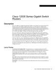
The Cisco 12000 Series Routers are part of Cisco’s premier routing product family and play an integral
part in the network architecture. The Cisco 12000 Series Routers were designed and developed for the
core of service provider and enterprise IP backbones.
The Cisco 10720 Router provides IP services to users at optical speeds at the edge of their networks. The
Cisco 10720 Router provides network access using Ethernet and Dynamic Packet Transport (DPT)
technology for optical connectivity. Each router is equipped with one uplink card and one Ethernet
access card.
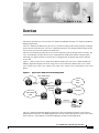
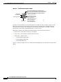
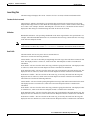
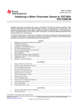
Figure 1-1 shows a typical Cisco 12000 Series Routers deployment. The Cisco 12000/10720 Router
Manager application supports the entire range of the Cisco 12000 Series Routers like: Cisco 12008,
Cisco 12012, Cisco 12016, Cisco 12404, Cisco 12406, Cisco 12410, Cisco 12416 and the Cisco 10720
Router.
Figure 1-1
Typical Cisco 12000 Series Router Deployment
Cisco 12000 series
internet router
ISP
Gig Eth
Telco
switch
PoS
SONET(SDH)
VATM/GE
PoS
Leased line
Frame Relay
ATM
Ethernet
56584
ATM/MPLS
Cisco EMF and
C12kM server
The Cisco 12000/10720 Router Manager application works in conjunction with the Cisco Element
Management Framework (Cisco EMF) application to provide element management for the Cisco 12000
Series and Cisco 10720 Routers. The Element Manager includes FCAP management.
Cisco 12000/10700 v3.1.1 Router Manager User Guide
OL-4455-01
1-1
Chapter 1
Overview
Cisco Element Manager Framework (Cisco EMF) Software
This chapter describes the following information:
•
Cisco Element Manager Framework (Cisco EMF) Software
•
Cisco 12000/10720 Router Manager Software
•
Key Features of the Cisco 12000/10720 Router Manager Software
•
Accessing Online Help
Cisco Element Manager Framework (Cisco EMF) Software
Cisco EMF is an open carrier class management system, designed to integrate with third party products
and proprietary operational support systems.
Many different management protocols, both standards-based and proprietary, are supported by
Cisco EMF in a transparent manner. New network devices are managed instantly and new management
applications can be quickly developed to meet new requirements.
Cisco EMF systems architecture provides a distributed network management solution designed to
manage large-scale networks. Cisco EMF provides the performance required within the logical and
physical architecture and provides user interfaces that support the need to perform mass operations to
large domains within the overall network. In addition, due to the distributed nature of Cisco EMF,
administration tools are provided to “manage” the management system. Refer to the Cisco Element
Management Framework User Guide Release 3.2 (78-12536-01) for further details.
Map Viewer is the primary entry point into the Cisco 12000/10720 Router Manager software. When Map
Viewer is launched, the application is displayed corresponding to the highlighted map icon in the
hierarchy pane. You can easily monitor the status of all network elements or abstractions of elements
contained within the network and you can launch any additional applications available. See “Map Viewer
(Viewer)” section on page 3-6 for further details.
Cisco 12000/10720 Router Manager Software
The Cisco 12000/10720 Router Manager application is a carrier class Element Manager (EM) that allows
you to manage Cisco 12000/10720 Routers. Cisco 12000/10720 Router Manager adds custom windows
and modeling behavior to the standard Cisco EMF to allow the management of the Cisco 12000 Series
and Cisco 10720 Routers.
Note
This Guide describes the concepts and operating instructions for the Cisco 12000/10720 Router
Manager. Refer to the Cisco Element Management Framework User Guide Release 3.2 (78-12536-01)
for further details on Cisco EMF.
Key Features of the Cisco 12000/10720 Router Manager Software
Cisco 12000/10720 Router Manager features include the following:
•
Maps for Chassis representation of Cisco 12000/10720 Router objects
•
Cisco 12000/10720 Router Manager windows and wizards—Eliminate the need for operators to
have detailed Cisco IOS software and SNMP-based knowledge for individual interface or system
parameter commands
Cisco 12000/10700 v3.1.1 Router Manager User Guide
1-2
OL-4455-01
Chapter 1
Overview
Key Features of the Cisco 12000/10720 Router Manager Software
•
Cisco 12000/10720 Router Manager deployment—Eases deployment of large networks by enabling
template-based element configuration, operations, administration, and maintenance
– Pre-deployment of chassis, GRP and line cards
– AutoDiscovery—Automatically discovers existing Cisco 12000/10720 routers
•
Comprehensive fault management system—For chassis, line cards and interfaces
•
Configuration Backup/Restore using RME—Uses Resource Manager Essentials to back up and save
the running configuration of a device and its modules so that if a hardware failure occurs, you can
restore configuration
•
Configuration Editor—Uploads and saves the running configuration on a device after editing
•
Configuration operations—Performs in bulk to numerous Cisco 12000/10720 routers
•
Cisco 12000/10720 Router Manager Management—Fault, Configuration, Accounting and
Performance (FCAP) Element Management of Cisco 12000 Series Routers using Cisco EMF
windows
•
Interface profiles—Enables you to apply the same parameters to a large number of objects at one
time
•
Layer 3 QoS support—Includes Committed Access Rate (CAR), Weighted Random Early Detection
(WRED), WRED ToFab and Modified Deficit Round Robin (MDRR)
•
Line cards and interfaces—Supports various line cards and interfaces, such as packet-over-SONET
(POS), Asynchronous Transfer Mode (ATM), Digital Signal 3 (DS3), Dynamic Packet Transport
(DPT), Spatial Reuse Protocol (SRP) and Gigabit and Fast Ethernet
•
Cisco IOS releases—Easily downloads new software releases from Cisco 12000/10720 Router
Manager onto devices using RME
•
ATM Connections Management—Uploads existing PVCs and associated QoS profiles from any
device into the Cisco 12000/10720 Router Manager and also manual deployment and management
of PVCs and SVCs
•
Subchassis discovery—Determines the physical chassis contents, such as line cards and interfaces
•
Rediscover Line Cards after online insertion or removal (OIR)
•
BGP and OSPF Protocols Management—Configuration and Fault Management for BGP and OSPF
routing protocols and uploading BGP Address Family configurations
•
Route Processor Redundancy (GRP and PRP) support for chassis management
•
Complete support for IP Routing, TCP and UDP Status Management
•
MPLS Management—Fault Management and Performance Management for MPLS Interfaces and
Sub-Interfaces, Fault Management for LDP Entities and MPLS Tunnels, Configuring MPLS and
VRF Traps
•
VRF Management—Configuration of VRFs in the EM. Creation of VRFs in the device through EM
and Association of VRFs to Interfaces. Fault Management for VRFs
•
VLAN Management—Configuration and performance monitoring of the VLAN sub-interfaces
•
VLAN Synchronization—Uploads the existing VLAN information from the network into Cisco
12000/10720 Router Manager
Cisco 12000/10700 v3.1.1 Router Manager User Guide
OL-4455-01
1-3
Chapter 1
Overview
Accessing Online Help
Accessing Online Help
Each window has the option to click the Help icon, or to select Help from the menu bar. A list of help
topics is displayed.
Cisco 12000/10700 v3.1.1 Router Manager User Guide
1-4
OL-4455-01
C H A P T E R
2
Concepts
This chapter describes Cisco 12000/10720 Router Manager concepts and covers the following
information:
•
Cisco 12000/10720 Router Manager Objects and Interfaces
•
Views
•
Cisco 12000/10720 Router Manager Object States
Cisco 12000/10720 Router Manager Objects and Interfaces
Cisco 12000/10720 Router Manager manages both physical and logical objects, as follows:
•
Physical—Represents tangible components and devices such as the chassis (hardware frame), line
cards, and interfaces
•
Logical—Represents intangible, more abstract features, such as ATM connections, Layer 3 Quality
of Service (QoS) objects and VLAN sub-interfaces
Fault, Configuration, Accounting and Performance (FCAP) windows are accessible on both physical and
logical EM objects, in the form of FCAP menu options that appear when you right-click on any object
in Cisco 12000/10720 Router Manager. FCAP functionality provides a complete management interface
to the features of the Cisco 12000/10720 Router.
This section covers the following areas:
•
Physical Objects
•
Cisco 12000/10720 Router Chassis
•
Supporting Modules
•
Physical Interfaces and Technologies
•
Logical Objects
Cisco 12000/10700 v3.1.1 Router Manager User Guide
OL-4455-01
2-1
Chapter 2
Concepts
Cisco 12000/10720 Router Manager Objects and Interfaces
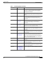
Physical Objects
Table 2-1 lists all physical objects created in Cisco 12000/10720 Router Manager and the management
functions that can be performed on each object.
Table 2-1
Physical Objects and Management Functions
Cisco 12000/10720 Router Manager Physical Object
Management Functions
Chassis—The hardware frame of the Cisco 12000/10720 Router,
which houses all subchassis objects (modules).
Command Log
Configuration
Configuration Backup/Restore
Configuration Editor
Fault Management
Initiate Telnet Service
Inventory
IOS Image Download
Launch Web Console
Management Information
SNMP Management
System Log
APS Status
RPR Configuration
RPR Status
GRP (Gigabit Route Processor)—There can be up to two GRPs in Configuration
a chassis. The primary GRP is the CPU or “brains” of the router. Fault Management
The secondary GRP is redundant.
Inventory
Performance
Line Cards—There are various types of line cards within a chassis Configuration
Fault Management
(for example, ATM, Ethernet, SRP, POS, E3, DS3 and Modular
Inventory
Ethernet). Each of these line cards holds a given number of
physical interfaces (ports).
Note
Physical Interfaces—Each line card has at least one, if not
multiple, physical interfaces (ports). The type of physical interface
is equivalent to the type of line card the interface resides on. Each
physical interface can support multiple technologies (for details,
see “Physical Interfaces and Technologies” section on page 2-5)
The line card type determines what specific technologies are
supported by an interface.
Profile
Configuration
Fault Management
Performance
Status
Supporting Modules—Additional subchassis cards and modules:
the switch fabric card (SFC), clock scheduler card (CSC), AC or
DC power supply module, blower module, and fan tray module.
Configuration
Fault Management
Inventory
The Cisco 10720 chassis does not support the Configuration Editor.
The physical objects and interfaces displayed in Table 2-1 are traced as follows:
•
The chassis contains the GRPs, supporting modules, and all line cards
•
The line cards contain the physical interfaces.
Cisco 12000/10700 v3.1.1 Router Manager User Guide
2-2
OL-4455-01
Chapter 2
Concepts
Cisco 12000/10720 Router Manager Objects and Interfaces
See the “Views” section on page 2-11 for further details on hierarchies within Cisco EMF and Cisco
12000/10720 Router Manager.
Tip
Physical objects contained within a chassis are often referred to as subchassis objects or
modules.
Cisco 12000/10720 Router Chassis
The Cisco 12000/10720 Router Manager application supports the entire range of Cisco 12000 Series
Router chassis like: Cisco 12008, Cisco 12012, Cisco 12016, Cisco 12404, Cisco 12406, Cisco 12410,
Cisco 12416 and the Cisco 10720 Router chassis.
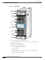
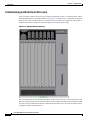
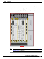
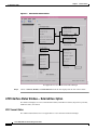
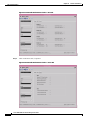
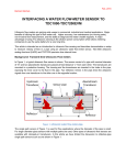
Figure 2-1 displays a Cisco 12016 Router chassis as an example, and identifies the modules and
sub-modules that you would find.
Cisco 12000/10700 v3.1.1 Router Manager User Guide
OL-4455-01
2-3
Chapter 2
Concepts
Cisco 12000/10720 Router Manager Objects and Interfaces
Figure 2-1
Cisco 12016 Chassis
PWR OK
Power shelf and
power supplies
PWR OK
FAULT
PWR OK
FAULT
TEMP
FAULT
TEMP
I LIM
TEMP
I LIM
I LIM
Upper blower
module
CDHNT
CDHNT
RA
RA
LOOP
DOWN
LOOP
DOWN
CD
CD
LA
LA
Upper cable
management
bracket
TX
TX
0
0
RX
RX
TX
TX
0
1
1
RX
RX
TX
TX
2
2
E IER T
TIV RR PK
AC CA RX
CT
EJE
RX
RX
3
TX
TX
E IER LL
TIV RR CE
AC CA RX
4
4
RX
RX
E IER T
TIV RR PK
AC CA RX
X
AU
T
SE
RE
RX
RX
AL JOR OR
ITIC MA MIN
CR
0
E IER T
TIV RR PK
AC CA RX
3
T-1
SLO
T-0
SLO
TX
TX
1
RP
TX
TX
5
2
5
RX
RX
T
O/L
AC
E
OL
NS
CO
TX
E IER T
TIV RR PK
AC CA RX
6
RX
TX
ALARM
7
3
RX
TX
8
E IER T
TIV RR PK
AC CA RX
RX
K
LIN
TX
LL
CO RX
Alarm card
TX
9
L
FAI
LED
AB
EN
L
FAI
RX
LED
AB
EN
MII
TX
RJ45
10
RX
TX
1
ROUTE PROCESSOR
P/H/F
FAST ETERNET
2
ALARM
C
SF
OC-12/STM-4 ATM
1
6DS3–SMB P/H/F
0
RX12DS3–SMB
C
CS
Q OC-3/STM-POS
OC-48/STM-16-SCPOS
11
0
Upper card cage
Air filter door
2
ALARM
C
SF
1
0
1
Q OC-3/STM-POS
C
CS
P/H/F
6DS3–SMB P/H/F
RX12DS3–SMB
OC-48/STM-16-SCPOS
L
FAI
LED
AB
RX
9
T
O/L
AC
2
CR
AL JOR OR
ITIC MA MIN
E IER T
TIV RR PK
AC CA RX
TX
TX
3
3
RX
RX
E IER T
TIV RR PK
AC CA RX
TX
1
TX
E IER T
TIV RR PK
AC CA RX
0
RX
RX
0
0
LOOP
Lower blower
module
26194
CDHNT
RA
DOWN
LA
CD
TX
TX
CD
LOOP
LA
CDHNT
RA
DOWN
Lower cable
management
bracket
TX
TX
1
1
RX
RX
TX
TX
2
2
RX
RX
EJE
CT
T-1
SLO
T-0
SLO
0
X
AU
T
SE
RE
TX
4
4
RX
RX
E IER LL
TIV RR CE
AC CA RX
TX
5
5
RX
RX
Lower card cage
TX
E
OL
NS
CO
6
E IER T
TIV RR PK
AC CA RX
RX
TX
ALARM
7
3
RX
TX
8
RX
E IER T
TIV RR PK
AC CA RX
TX
TX
LL
CO RX
K
LIN
Alarm card
TX
MII
RJ-
10
45
RX
EN
L
FAI
LED
AB
EN
TX
0
11
FAST ETERNET
OC-12/STM-4 ATM
ROUTE PROCESSOR
Switch fabric
card cage
(behind filter door)
The Cisco 12016 chassis supports the following components:
•
Power shelf and power supplies—Contains either 3 AC (shown) or 4 DC power modules
•
Upper and lower blower modules
•
Upper and lower cable management brackets
•
Upper card cage, which contains the following:
– 1 Non-configurable alarm card in far left slot
– 1 GRP in far right slot
– Up to 7 line cards
•
Air filter door—Behind it is the switch fabric card cage, which contains the following:
– 2 CSCs (one is optional for redundancy)
– 3 SFCs
Cisco 12000/10700 v3.1.1 Router Manager User Guide
2-4
OL-4455-01
Chapter 2
Concepts
Cisco 12000/10720 Router Manager Objects and Interfaces
•
Lower card cage, which contains the following:
– 1 Non-configurable alarm card in far right slot
– 1 Optional GRP in far left slot
– Up to 8 line cards
Supporting Modules
Cisco 12000/10720 Router Manager supports five types of supporting modules within a Cisco 12000
Series Router chassis. Some modules only apply to certain chassis types.
•
CSC (Clock Scheduler Card)—CSCs handle requests from line cards, issue grants to access the
switch fabric cards, and provide a reference clock to all the cards in the system to synchronize data
transfer across the crossbar. Each chassis must have at least one CSC.
•
SFC (Switch Fabric Card)—SFCs receive the scheduling information and clocking reference from
the CSC cards and perform the switching functions.
•
AC or DC Power Supply Module—Chassis can be ordered with either AC or DC power supply
modules, having anywhere from one to four AC or DC-input power supplies, depending upon the
specific chassis.
•
Blower Module—The Cisco 12012 and 12016 Routers contain two blower modules, which circulate
cooling air through the card cages in the chassis.
•
Fan Tray—The Cisco 12008 Router contains a fan tray, which circulates cooling air through the card
cage in the chassis.
Linecards
Refer “Manually Deploying Line Cards” section on page 3-38 for details of all the supported technology
specific linecards.
Physical Interfaces and Technologies
Physical interfaces are modeled as objects below the parent line card. Some generic properties are
supported by all the interfaces. As mentioned before, the type of line card characterizes the type of
physical interface; for example, an ATM line card will only support ATM interfaces. However, there can
be multiple technologies supported on that physical interface. For example, ATM physical interfaces can
support the following:
Note
•
Internet Protocol (IP)
•
ATM
•
SONET
Cisco 12000/10720 Router Manager handles both SDH and SONET in the same manner.
The Cisco 12000/10720 Routers support both SDH and SONET. For a comparison chart of
SONET and SDH speeds, see Appendix A, “SONET/SDH Conversion Chart.”
Cisco 12000/10700 v3.1.1 Router Manager User Guide
OL-4455-01
2-5
Chapter 2
Concepts
Cisco 12000/10720 Router Manager Objects and Interfaces
Tip
The technologies supported by an interface are exposed within FCAP-based management
windows. It is important to understand the relationship of physical interfaces to
technologies in order to properly manage an interface.
Table 2-2 outlines each physical interface and the technologies it supports. Also included are the
different FCAP-based windows that are applicable to each physical interface and technology. For
example, if you want to configure an ATM interface, look in the table under ATM, and you will notice
that four technologies apply: Generic, ATM, SONET, and IP. This means that you should open the
configuration windows for these four technologies and configure the fields within, in order to completely
configure an ATM interface.
Table 2-2
Physical Interfaces, Related Technologies and Windows
Physical Interfaces
Technologies Supported and Related Windows
DS-3
Generic—Configuration, Status, Performance
DS-3—Status, Performance
IP—Configuration
POS
Generic—Configuration, Status, Performance
SONET—Status, Performance
POS—Configuration, Profile, APS Configuration, APS Status
IP—Configuration
ATM
Generic—Configuration, Status, Performance
ATM—Status, Configuration, Profile, Fault
SONET—Status, Performance
IP—Configuration
Ethernet
Generic—Configuration, Status, Performance
Ethernet—Performance, Configuration, HSRP Configuration, HSRP
Profile
IP—Configuration
SRP
Generic—Configuration, Status, Performance
SRP—Configuration, Status, Topology, Performance
SRP Side—Profile, Configuration, IPS Status, Performance
IP—Configuration
Logical Objects
Cisco 12000/10720 Router Manager supports three logical object types:
•
Note
•
Layer 3 QoS—Weighted Random Early Detection (WRED) or Committed Access Rate (CAR)
objects, such as Class of Service (CoS) Queue Groups, WRED ToFab policies, CAR policies, and
CAR access lists.
The Cisco 10720 Router does not support Layer 3 QoS objects.
ATM connections—Permanent Virtual Circuits (PVCs) or Switched Virtual Circuits (SVCs) can be
applied to ATM interfaces. The Cisco 10720 Router does not support ATM connections.
Cisco 12000/10700 v3.1.1 Router Manager User Guide
2-6
OL-4455-01
Chapter 2
Concepts
Cisco 12000/10720 Router Manager Objects and Interfaces
•
VLAN—Domain, VLAN, sub-interface objects. VLAN sub-interfaces can be configured on
Ethernet interfaces.
Table 2-3 describes the management functions for Layer 3 QoS logical configurations.
Table 2-3
Layer 3 QoS Logical Objects
Logical Object
Management Functions
WRED:
CoS queue groups
Create, configure, apply, modify, delete and remove CosQ groups, WRED
ToFab and CAR objects.
ToFab Policies
CAR:
CAR policies
CAR access lists
Software: VRF Policies
Create, configure, apply(to an interface) and remove(from device and
interface) VRF Policies
Table 2-4 describes the management functions for ATM logical objects.
Table 2-4
ATM Logical Objects
Logical Object
Management Functions You Can Perform
PVC
SVC
Upload, sync, create, configure, manage, and delete/connect/disconnect on
main or sub-interfaces. Status information can be collected and displayed
for PVC objects only.
Table 2-5 describes the management functions for VLAN objects.
Table 2-5
VLAN Objects
Logical Object
Management Functions You Can Perform
Domain,
VLAN
VLAN sub-interfaces
Create and delete on Domain objects. Create, configure, manage, and delete
on VLAN and sub-interfaces.
Use of Telecom Graphics Objects
Cisco EMF uses Telecom Graphics Objects (TGO) in the Map Viewer application. TGO is a
TeleManagement Forum (TMF) sponsored initiative to provide standard graphical representations for
network topology maps.
A TGO displays additional information icons on top of the existing object icons displayed in Map
Viewer. The additional icons indicate a variety of information (for example, information on the state of
the object or event status information). Figure 2-2 provides an example of a TGO.
Cisco 12000/10700 v3.1.1 Router Manager User Guide
OL-4455-01
2-7
Chapter 2
Concepts
Cisco 12000/10720 Router Manager Objects and Interfaces
Sample Telecom Graphical Object
Event unacknowledged count and state (color).
The color of the object balloon shows the most severe
unacknowledged event status. Event severities are
by a letter in the balloon (for example, the letter C
signifies a Critical alarm.
Object state
(icon/hatching)
Object class bitmap
Object name
Event outstanding state
(outline and name colors)
Color of outline and
object name shows most
severe event status of
any acknowledged or
unacknowledged event
41789
Figure 2-2
An object is a representation of a network element. For example, the object could be a node or a link.
Each object shown in the right window provides pictorial cues which provide information about its
associated network element. The information can be structural information; for example, a network
element name or state and event information such as “out of service.”
Each object can display the following information about its associated network element:
•
Object name—Name that the user gives to the object
•
Object class—Class indicates a different kind of element
•
Object state—(ANSI T1-232):
– Event unacknowledged count
– Event unacknowledged state
– Event outstanding state
Figure 2-3 shows an example of a Cisco 12000 chassis map displaying a few of the TGO icons that could
appear.
Cisco 12000/10700 v3.1.1 Router Manager User Guide
2-8
OL-4455-01
Chapter 2
Concepts
Cisco 12000/10720 Router Manager Objects and Interfaces
Figure 2-3
Sample Cisco 12000 Chassis Showing Telecom Graphical Objects
Refer to the Cisco Element Management Framework User Guide Release 3.2 for further information on
the type of TGO objects that can appear in the Cisco 12000/10720 Router Manager.
Cisco 12000/10700 v3.1.1 Router Manager User Guide
OL-4455-01
2-9
Chapter 2
Concepts
Cisco 12000/10720 Router Manager Objects and Interfaces
OSI Mappings
Table 2-6 gives the complete list of OSI mappings for all combinations of the Admin and Operational
status.
Table 2-6
Note
OSI Mappings for the different combinations of the Admin and Operational Status
Operational Status
Admin Status
OSI Mapping
Up
Up
EnabledActiveUnloc
ked(Availability:
Providing Service)
Down/Testing
Down
DisabledIdleLocked
Down/Testing
Up
EnabledIdleUnlocked
(Availability:
Degraded)
Down/Testing
Testing
DisabledIdleLocked
Icon Representation
Although, the EnabledIdleUnlocked is used for the errored state (admin status up), this does not follow
the TGO standard definitions, however within the standard definitions there is no available combination
that accurately represents this state.
Cisco 12000/10700 v3.1.1 Router Manager User Guide
2-10
OL-4455-01
Chapter 2
Concepts
Views
Views
Cisco 12000/10720 Router Manager views can be accessed by clicking on the Viewer icon in the
Cisco EMF launchpad. These views appear in the frame at the left of the window when you open the
Map Viewer window (see Figure 2-4 on page 2-11).
Cisco 12000/10720 Router Manager views model hierarchical relationships between objects, both
physical and logical. Objects are organized into different views and can exist in multiple views
simultaneously by reference. Each object can have a number of parent and child objects. You can access
Cisco 12000/10720 Router Manager objects by navigating through one of the views to find the object.
You can navigate through views by expanding text. Click on the + sign next to any object to expand text.
A - sign next to an object indicates there is no more text to expand. Each view represents a different way
of containing and grouping objects.
Cisco 12000/10720 Router Manager adds specific views to the standard views supplied by Cisco EMF.
The standard Cisco EMF views are the Physical and Network views (for further information on these
views, refer to the Cisco Element Management Framework User Guide Release 3.2).
The number in parenthesis next to a view indicates how many top-level objects are contained within the
view.
The Views section covers the following areas:
•
Component Managed View
•
Layer 3 QoS View
•
Network View
•
Physical View
•
VLAN View
Component Managed View
The Component Managed view displays all objects within the Cisco EMF system. The Component
Managed view displays all the physical objects and most of the logical objects.
Figure 2-4
Hierarchy of Component Managed View
Site
Cisco GSR chassis
Cisco 10700 chassis
Line
cards
GRP
Ethernet
interfaces
Physical
interfaces
Ethernet
interfaces
Physical
interfaces
Ethernet
interfaces
VLAN subinterfaces
Logical
PVCs
VLAN subinterfaces
Logical
PVCs
VLAN subinterfaces
GRP
Supporting modules
Supporting modules
Line
cards
Line
cards
RP Supporting modules
89710
Cisco GSR chassis
Cisco 12000/10700 v3.1.1 Router Manager User Guide
OL-4455-01
2-11
Chapter 2
Concepts
Views
Layer 3 QoS View
The Layer 3 QoS view displays only Layer 3 QoS objects within Cisco 12000/10720 Router Manager,
such as the following:
•
Access Lists
•
CAR objects
•
WRED objects
You can work within this view to create and configure Access Lists or CAR or WRED objects by
accessing the respective Cisco 12000/10720 Router Manager menus.
Network View
This view displays all network devices within their relevant networks and subnets. The auto-discovery
system of Cisco EMF uses this view to calculate which devices have already been added to the system,
so that it does not try to discover the same device multiple times. For details on auto-discovery, see “IP
Auto Discovery of the Cisco Chassis” section on page 3-19.
Physical View
Physical view displays all the physical objects. Objects in the Physical view are ordered according to
their relative physical location.
Figure 2-5
Hierarchy of Physical View
Site
CiscoGSRChassis
GRP
Supporting modules
Line
cards
Physical
interfaces
GRP
Supporting modules
Ethernet
interfaces
Cisco 10700 Chassis
Line
cards
Physical
interfaces
GRP
Supporting module
Ethernet
interfaces
GRP
Physical
interfaces
84827
Ethernet
interfaces
CiscoGSRChassis
VLAN View
The VLAN view displays the VLAN objects in Cisco 12000/10720 Router Manager. The VLAN view
can contain one or more domains. A domain is a user-defined grouping of the VLAN objects. This
grouping may be done on a customer name basis, on logical groupings like 'Accounting Vlans' or it could
Cisco 12000/10700 v3.1.1 Router Manager User Guide
2-12
OL-4455-01
Chapter 2
Concepts
Cisco 12000/10720 Router Manager Object States
be any other user maintained VLAN grouping. There can be mulitple domains in the VLAN view and
each domain can contain mulitple VLAN objects. The same VLAN id can be duplicated across different
domains. Each VLAN object can have multiple sub-interface objects.
Note
The sub-interface objects are shown only under the VLAN objects and in the component managed view.
Only Ethernet sub-interfaces are displayed.
Cisco 12000/10720 Router Manager Object States
Cisco 12000/10720 Router Manager object states reflect the life cycle of an object. Whatever stage the
object is in at any given time is reflected in the state type. The state of an object can change frequently,
depending upon what actions are being performed on the object. All objects in Cisco 12000/10720
Router Manager have a state assigned to them which appears at the bottom left corner of each FCAP
window for a selected object (see Figure 2-6).
Figure 2-6
Cisco 12000/10720 Router Manager Object States
The two most common object states are Normal and Decommissioned. For example, when you deploy a
line card in Cisco 12000/10720 Router Manager, the initial state of the line card is decommissioned. You
can then commission the line card to begin active management (for details on how to commission a
module, see “Commissioning a Selected Module” section on page 5-4). When you commission the line
card, it passes through two transitory states: discovery and commissioning. The commissioning process
determines which state to move the object into (typically Normal). This example reflects the basic
process of deploying and commissioning an object.
Certain states ripple down to any objects below. For example, if you decommission a chassis, all
subchassis objects are also decommissioned. If you enable performance logging on a line card, all
interfaces on the line card are also transitioned to performance logging.
By default, FCAP windows refresh at a rate dependent upon the type of window. For example, inventory
windows are refreshed at a lower rate than performance windows. The average refresh rate is every 30
seconds.
The following sections describe the possible states that an object may be in and provides a description
of these states.
Cisco 12000/10700 v3.1.1 Router Manager User Guide
OL-4455-01
2-13
Chapter 2
Concepts
Cisco 12000/10720 Router Manager Object States
Decommissioned State
The decommissioned state indicates that an object is not managed. When you manually deploy an object,
it is normally placed into a decommissioned state.
Tip
Initially deployed objects are decommissioned to leave you with the option of managing
the object or not. If you want to manage the object, you need to commission the object.
The following actions occur on a decommissioned object:
•
Active management stops
•
All sub objects are also decommissioned
Decommission buttons are located in Chassis, Module, Interface and VLAN Configuration windows.
When you decommission an object, any children of that object also change their state to
decommissioned. For example, if you decommission a chassis, all objects within that chassis (GRP card,
line cards, interfaces, connections) are also decommissioned. If you decommission a line card, all
interfaces and connections on that line card are decommissioned, and so on.
Normal State
The normal state indicates that an object is operational. When any physical object enters the normal
state, Cisco 12000/10720 Router Manager performs heartbeat polling on the objects. The heartbeat
polling interval for chassis object is 1 minute and for all modules and interface objects, the heartbeat
polling interval is 5 minutes.
Errored
When the object is in a non-operational state, it moves into the errored state. In the errored state,
performance polling (if activated) is stopped; however, the heartbeat polling (which polls an object every
5 minutes to verify its existence and current state) continues, until the device responds positively to the
heartbeat request. When the module is operational again, it responds positively to the heartbeat requests,
and then moves into the state which it previously held.
Performance Logging On
When performance logging is started on an object in the Normal state, the object moves into the
Performance Logging On state. This means that the performance data is collected on the object and is
viewed in the Performance windows or the Performance Manager windows. Performance logging is
enabled for GRPs, interfaces and VLAN sub-interfaces. You can enable performance logging on a global
scale or on an individual object basis. Enabling global performance logging puts all subchassis objects
into a performance logging on state. However, remember that only GRPs and interfaces actually collect
performance data. (For more information on global performance logging, see “Starting Global
Performance Logging” section on page 4-9.
Performance logging occurs every 15 minutes. This means that when you enable performance logging
or global performance logging initially on an object, it takes 15 minutes for the data to be collected and
displayed in Cisco 12000/10720 Router Manager performance menus.
Cisco 12000/10700 v3.1.1 Router Manager User Guide
2-14
OL-4455-01
Chapter 2
Concepts
Cisco 12000/10720 Router Manager Object States
Heartbeat polling is performed on an object in the performance logging on state. If the object moves into
the errored state, it is returned to the performance logging on state when the error is rectified. For
example, if a line card is in the performance logging on state and it goes down in the device, the EM
moves the line card into the errored state. When heartbeat polling finds that the line card is operational,
the EM restores the line card to the performance logging on state.
Lost Comms
The lost comms (lost communications) state indicates that the object is not contactable. Cisco
12000/10720 Router Manager can apply this state to a chassis, module, or interface. During this state,
heartbeat polling is performed on the object. When the object becomes contactable again, it moves out
of the lost comms state.
Discovery Lost Comms
The discovery lost comms state is quite similar to the lost comms state; however, this state only occurs
during subchassis discovery. For example, if you commission a chassis (which begins the process of
subchassis discovery), and if a pre-deployed line card is not present then, the line card is moved into the
discovery lost comms state. When the linecard is re-inserted in the device, subchassis discovery is
resumed, and the object moves out of the discovery lost comms state.
Mismatched
The mismatched state occurs when a mismatch is found between what is in the hardware and what is
deployed in Cisco 12000/10720 Router Manager. For example, say you are expecting an ATM OC-3 line
card. So you predeploy and perform offline configuration in Cisco 12000/10720 Router Manager to
prepare for that type of line card. Now, when the line card becomes available and is placed into the
chassis, it is not an ATM OC-3 line card, but a POS OC-3 line card. So when Cisco 12000/10720 Router
Manager detects the new line card, it finds a mismatch. The line card gets placed into the mismatch state,
and a major alarm is raised against the line card.
Transient Object States
Certain states in Cisco 12000/10720 Router Manager are temporary or transient, that is, they exist only
for a short time while a process is being performed. The following states are transient:
•
Download—Temporary state that is assigned to objects in Cisco 12000/10720 Router Manager when
an Cisco IOS Download is being performed.
•
Discovery—Temporary state that is assigned to objects in Cisco 12000/10720 Router Manager
during subchassis discovery. Objects are being discovered at this stage.
•
Synchronization—This temporary state is applicable only for chassis. During this state, the EM
synchronizes with its ATM connection information with the device.
Cisco 12000/10700 v3.1.1 Router Manager User Guide
OL-4455-01
2-15
Chapter 2
Concepts
Cisco 12000/10720 Router Manager Object States
Cisco 12000/10700 v3.1.1 Router Manager User Guide
2-16
OL-4455-01
C H A P T E R
3
Getting Started
This chapter describes the typical tasks you should complete to start using the Cisco 12000/10720
Router Manager application. See Figure 3-1 on page 3-2 for further details.
This chapter provides the following information:
•
Cisco 12000/10720 Router Manager Workflow
•
Starting Cisco EMF and Cisco 12000/10720 Router Manager
•
Deployment
Cisco 12000/10720 Router Manager Workflow
Figure 3-1 outlines the steps involved in installing, configuring and using the Cisco 12000/10720 Router
Manager application.
Cisco 12000/10700 v3.1.1 Router Manager User Guide
OL-4455-01
3-1
Chapter 3
Getting Started
Cisco 12000/10720 Router Manager Workflow
Figure 3-1
Workflow for Cisco 12000/10720 Router Manager
Install Cisco EMF
software
Install C12000/10720M
software
Start CEMF
Start a Cisco EMF
session
Deploy objects
Enter username
and password
Perform Subchassis
discovery
Review deployment
and check for alarms
Module
Management
Fault
Management
Change
Management
Interface
Management
ATM
Connections
VLAN
Sub-interface
84835
Chassis
Management
Layer 3 QoS
Cisco 12000/10700 v3.1.1 Router Manager User Guide
3-2
OL-4455-01
Chapter 3
Getting Started
Starting Cisco EMF and Cisco 12000/10720 Router Manager
Starting Cisco EMF and Cisco 12000/10720 Router Manager
The Cisco 12000/10720 Router Manager application is viewed through the Cisco Element Management
Framework (Cisco EMF). It is important to understand how Cisco EMF works before you use the Cisco
12000/10720 Router Manager application (refer to the Cisco Element Management Framework User
Guide for further details). Cisco 12000/10720 Router Manager automatically starts when you start a
Cisco EMF user session.
Note
Each active Cisco EMF session uses a single Cisco EMF user license.
This section covers the following:
•
Starting a Cisco EMF User Session
•
Launchpad
•
Quitting a Cisco EMF User Session
Starting a Cisco EMF User Session
Note
Cisco EMF should already be running. When you try to invoke a Cisco EMF session, and
if you receive a message that Cisco EMF is not running, contact your system administrator,
or refer to the Cisco Element Management Framework User Guide for further details.
To start a Cisco EMF user session, proceed as follows:
Step 1
From the command line on the terminal window, enter <CEMF_ROOT>/bin/cemf
Note
<CEMF_ROOT>
session
is the Cisco EMF installation root directory (for example,
/opt/CEMF).
Cisco 12000/10700 v3.1.1 Router Manager User Guide
OL-4455-01
3-3
Chapter 3
Getting Started
Starting Cisco EMF and Cisco 12000/10720 Router Manager
The Login window (see Figure 3-2) appears.
Figure 3-2
Login Window
Step 2
Enter a valid user name and password.
Step 3
Click Ok to proceed.
When an unknown user name or password is entered, an error is displayed. Click Ok, then enter a valid
user name and password.
Note
You have three attempts to enter a valid user name and password.After the third failed attempt
the session does not start and the Login window closes.
When a valid user name and the password are entered, the session starts and the Cisco EMF Launchpad
(see Figure 3-3) appears.
Cisco 12000/10700 v3.1.1 Router Manager User Guide
3-4
OL-4455-01
Chapter 3
Getting Started
Starting Cisco EMF and Cisco 12000/10720 Router Manager
Launchpad
The icons displayed in the CEMF Manager and Event Manager panels on the Launchpad represent the
applications provided by this Cisco EMF installation. Extra icons may appear when additional packages
are installed. The icons (see Figure 3-3) represent the standard Cisco EMF tools.
Figure 3-3
Launchpad
Viewer icon - Launches MapViewer
Groups icon - Launches the Object Group Manager
Access icon - Launches Access Manager
Events icon - Launches the Query Editor and Event Browser
80864
Discovery icon - Launches Auto Discovery
PreFilter icon - Launches Pre Filtering Application
Event Grps icon - Launches Event Groups Application
Thresholds icon - Launches Thresholding Regimes Application
Notify icon - Launches Notification Profile Application
Launching an Application
From the Launchpad, click the desired icon. The application is launched. A “busy” icon and a message
in the status bar is displayed during launch. More than one instance of an application can be opened at
any time.
Note
If an application is already open, it appears in the Windows list. Click Window and choose the
application you require from the drop down menu.
Cisco 12000/10700 v3.1.1 Router Manager User Guide
OL-4455-01
3-5
Chapter 3
Getting Started
Starting Cisco EMF and Cisco 12000/10720 Router Manager
Map Viewer (Viewer)
MapViewer allows complete flexibility in viewing, building, and monitoring your network using
graphical representations of network elements.
MapViewer is the primary entry point into the Cisco 12000/10720 Router Manager. When the
MapViewer application is launched, a window appears corresponding to the highlighted map icon in the
hierarchy pane. You can easily monitor the status of all network elements or abstractions of elements
contained within the network and you can launch any of the additional applications on the Launchpad.
Refer to the Cisco Element Management Framework User Guide for further details on the MapViewer
application.
Groups
Object Group Manager allows you to organize network elements into object groups. An object group is
a collection of objects which are related in some way. They may all be the same type of equipment or all
belong to the same customer.
Object groups can be built manually or by building a query. Some Cisco EMF subsystems may also build
object groups which may be visible and usable by the Cisco EMF user.
Refer to the Cisco Element Management Framework User Guide for further details on the Object Group
Manager application.
Access
User Access Control allows system administrators the opportunity to control the features of their system
that can be accessed by various levels of personnel. This is important for secure network management.
Refer to the Cisco Element Management Framework User Guide for further details on the User Access
Control application.
Event Browser (Events)
One of the most important aspects of Network Service Management is the ability to identify faults and
other events on the network and to take action to resolve them quickly and efficiently. For example, there
may be a power supply fault in a chassis which would require an engineer to be sent out to rectify the
fault. This fault is critical to the running of the network and would need prompt attention.
In Cisco EMF, when a condition (fault) occurs on a managed object in the network, the system is notified
immediately. Notification is shown as an event and can be viewed with the Event Browser (when
configured to do so).
Refer to the Cisco Element Management Framework User Guide Release 3.2 for further details on the
Event Browser application.
Discovery
Discovery allow you to examine the network for IP and SNMP devices and create a managed object for
each new device discovered. Auto-discovery can be opened from the Launchpad window or from a pop
up menu available on selected objects.
Refer to the Cisco Element Management Framework User Guide Release 3.2 for further details on the
Auto-discovery application.
Cisco 12000/10700 v3.1.1 Router Manager User Guide
3-6
OL-4455-01
Chapter 3
Getting Started
Starting Cisco EMF and Cisco 12000/10720 Router Manager
Notification Profiles
An important aspect of a monitoring system which captures and reacts to events on the network is when
and how a network operator is informed of these events. The Event Manager uses notifications for this.
For example, when the temperature of a line card rises 10 degrees above normal an e-mail might be sent
to the network operator warning of a potential problem and a minor event might be generated if the
temperature does not fall to within ten degrees of normal within twenty minutes.
Notification profiles are collections of notifications. Each notification profile has a name and description
and can be accessed by all Event Manager users. Each includes a list of notifications, and is run
following a trigger, which could be an event entering an event group, or a threshold breach in a
thresholding regime. For example, when the first event is received by an event group a notification
profile may be triggered which causes a sound to occur which alerts the operator. As well as audible
alerts, a notification could be set up to display on screen, or to trigger an external notification such as an
e-mail.
Refer to the Cisco Element Management Framework User Guide Release 3.2 for further details on the
Notification Profiles application.
Thresholding Regimes
A Thresholding Regime is a set of threshold conditions for specified object attributes which, when
breached, causes one or more notification profiles to be run. The Thresholding Regime defines which
attributes should be polled and on what period, and defines the thresholding conditions. The
Thresholding Regime specifies object groups which contain the objects whose attributes will be polled.
Refer to the Cisco Element Management Framework User Guide Release 3.2 for further details on the
Thresholding Regimes application.
Event Groups
Event Groups allows you to organize network elements into event groups, and also view the status of
these groups as scoreboards. Users can create, delete and modify event groups and scoreboards. Event
groups are available to all users.
Event groups can be any combination of objects derived from the managed object class. These groups
are set up using queries which can be configured to match your requirements. For example, you could
choose to monitor a particular device, specify a time period, and choose to look at events which are
warnings or critical. You define a query so that the event group only includes the events which meet the
criteria you define. As soon as the group is created it starts monitoring against the criteria specified in
the event query setup. Event groups created in the Event Groups application are persistent, they are not
cleared when the application is closed.
The Event Groups application also enables you to view the events associated with an event group in a
scoreboard format. This displays the overall status of the event group as a pie chart, with the associated
severity color coding. A scoreboard also shows the total number of events which have entered the event
group and the highest severity of the events in the group. An icon is displayed when a running
notification has been set up for the event group.
Event Groups is opened from the Launchpad.
Refer to the Cisco Element Management Framework User Guide Release 3.2 for further details on the
Event Groups application.
Cisco 12000/10700 v3.1.1 Router Manager User Guide
OL-4455-01
3-7
Chapter 3
Getting Started
Deployment
PreFilter
Event pre-filtering allows any event generated by the network which matches the criteria established in
the filter to be “filtered out”, and thus not saved into the database.
Pre-filtering offers you the capability to eliminate unwanted or undesired events from entering the
management system altogether. Pre-filtering is managed through the PreFilter application or from the
Event Browser. The PreFilter application is launched via the PreFilter icon on the Launchpad.
The PreFilter manager window displays, listing each of the pre-filters established, in the order in which
they are to be processed (from top to bottom).
Refer to the Cisco Element Management Framework User Guide Release 3.2 for further details on the
PreFilter application.
Quitting a Cisco EMF User Session
To quit the current Cisco EMF session, proceed as follows:
Step 1
Choose File > Quit. You see the question Do
you wish to quit the Cisco EMF Manager System?.
Step 2
Click Yes to quit the session (all active applications are closed and the session terminates) or click No
to return to the current Cisco EMF session.
Deployment
The first step toward managing a Cisco 12000/10720 Router is to deploy or pre-deploy the physical
objects that you want to manage. Deploying a physical object creates a representative object in
Cisco EMF and as a result, makes the Cisco 12000/10720 Router Manager application aware of the
physical object’s presence.
Cisco 12000/10720 Router Manager objects can be discovered automatically or deployed manually. For
example, to deploy a chassis, you can use auto discovery or you can manually deploy the chassis. If you
wish to deploy objects under the chassis, you can use subchassis discovery or manually deploy each
object (interfaces are automatically created when you deploy each line card).
If all or most of your chassis objects are physically present and if you have a large amount of objects to
deploy, you might want to automate these processes by using auto discovery. For example, if Cisco
12000/10720 Router Manager is installed into an existing network of Cisco 12000/10720 Routers, auto
discovery can dramatically reduce the amount of operator input required. If you only want to deploy a
few objects or if many of your objects are not yet physically present, you might want to deploy manually.
Cisco 12000/10720 Router Manager objects can be manually pre-deployed before the hardware arrives
on-site. See “Pre-deployment” section on page 3-58 for further details.
The following supporting modules can be deployed using subchassis discovery only, no manual
deployment is available for these modules:
•
AC or DC power supply card
•
Fan tray module
•
Blower module
Cisco 12000/10700 v3.1.1 Router Manager User Guide
3-8
OL-4455-01
Chapter 3
Getting Started
Deployment
You can also deploy either of the following logical objects:
Tip
•
SVC—See “Deploying an SVC Object” section on page 12-22
•
PVC—See “Deploying a PVC Object” section on page 12-18
•
VLAN Domain, VLAN and VLAN sub-interface—See “Deploying VLAN objects” section on
page 13-4
WRED (Weighted Random Early Detection) and CAR (Committed Access Rate) objects
are not created using the deployment wizard. For details on creating these objects manually,
see Chapter 11, “Layer 3 QoS.”
The Deployment section covers the following areas:
•
Deployment Process Outline
•
Manually Deploying a Generic Site Object
•
IP Auto Discovery of the Cisco Chassis
•
Manually Deploying a Cisco 12000/10720 Chassis
•
Commissioning and Subchassis Discovery
•
Manually Deploying Modules—Includes deploying line cards for 12000 Series router chassis
and10720 chassis
•
Pre-deployment
Deployment Process Outline
Producing a manageable Cisco 12000/10720 Router chassis in Cisco EMF is a three-stage process (see
Figure 3-4).
Cisco 12000/10700 v3.1.1 Router Manager User Guide
OL-4455-01
3-9
Chapter 3
Getting Started
Deployment
Figure 3-4
Deployment Process Workflow
IP Auto-discovery of
Cisco 12000/10720
series chassis
Stage 1: Manually
deploy a generic object
Stage 2: Chassis
level deployment
OR
Manual deployment of
the Cisco 12000/10720
series chassis
Stage 3: Sub-chassis
level deployment
Sub-chassis
Discovery
Manually deploy
Sub-chassis objects
AND/OR
84836
Optional
1.
The first deployment stage is to manually deploy a Generic (Site) object. A Site object can be looked
upon as a container object where you can deploy further objects that represent the
Cisco 12000/10720 Router chassis, line cards and interfaces contained within the chassis. See
“Manually Deploying a Generic Site Object” section on page 3-10 for further details.
2.
The second deployment stage is at the chassis level. The Cisco 12000/10720 Router chassis can be
auto discovered or manually deployed. See “IP Auto Discovery of the Cisco Chassis” section on
page 3-19 or the “Manually Deploying a Cisco 12000/10720 Chassis” section on page 3-20 for
further details.
Note
3.
You can pre-deploy objects (that is, manually predeploy objects) before the Cisco hardware
arrives on-site. See “Pre-deployment” section on page 3-58 for further details.
The third deployment stage is at subchassis level. This involves either subchassis discovery or
deploying subchassis objects (modules) manually. See “Commissioning and Subchassis Discovery”
section on page 3-26 or the “Manually Deploying Modules” section on page 3-30 for further details.
Manually Deploying a Generic Site Object
Generic objects are non-technology specific objects. When deploying a generic object, the information
you are prompted to provide differs according to the type and number of generic objects you are
deploying.
Table 3-1 displays a list of generic objects that can be deployed using Cisco 12000/10720 Router
Manager.
Cisco 12000/10700 v3.1.1 Router Manager User Guide
3-10
OL-4455-01
Chapter 3
Getting Started
Deployment
Table 3-1
Generic Object Deployment Templates
Object to be Deployed
Deployment Templates Available
Generic
Bay
IP Device
Region
SNMP Agent
SNMP MIB-2 Agent
SNMP Proxied Device
Site
This section provided an example that shows how to deploy a Site object. The deployment process differs
slightly for other types of generic object.
To deploy a Generic (Site) object, proceed as follows:
Step 1
Place the cursor over a relevant object to determine the objects you can deploy from. In this example we
will deploy a Site object from the Physical view.
Step 2
Click and hold down the right mouse button.
Step 3
Choose Deployment>Deploy Generic Objects....
Figure 3-5
Deploying a Site Object
The Deployment Wizard - Templates window appears (see Figure 3-6) displaying a list of available
generic object deployment profiles. Deployment profiles are templates that prompt you for the
appropriate information required to deploy the selected object successfully.
Cisco 12000/10700 v3.1.1 Router Manager User Guide
OL-4455-01
3-11
Chapter 3
Getting Started
Deployment
Figure 3-6
Deployment Wizard - Templates Window
Step 4
Select the generic object that you wish to deploy from the list supplied. In this example (shown in
Figure 3-6) shows the deployment profile for a Site object is selected. The Deployment Wizard steps
through a series of windows that prompt you for the information required to deploy the Site object.
Step 5
Click Forward.
Cisco 12000/10700 v3.1.1 Router Manager User Guide
3-12
OL-4455-01
Chapter 3
Getting Started
Deployment
The Deployment Wizard - Object Parameters window appears (see Figure 3-7).
Figure 3-7
Deployment Wizard - Object Parameters Window (1 of 2)
Step 6
Enter the number of Sites required. A single site was entered in this example.
Step 7
Click Forward.
Cisco 12000/10700 v3.1.1 Router Manager User Guide
OL-4455-01
3-13
Chapter 3
Getting Started
Deployment
Figure 3-8
Deployment Wizard - Object Parameters Window (2 of 2)
Step 8
Enter a Site name. Each Site must have a unique name. In this example the site is called Site-srp.
Step 9
Click Forward.
Cisco 12000/10700 v3.1.1 Router Manager User Guide
3-14
OL-4455-01
Chapter 3
Getting Started
Deployment
The Deployment Wizard - Views window appears.
Figure 3-9
Step 10
Deployment Wizard—Views Window
Click Select, to select a physical view.
Cisco 12000/10700 v3.1.1 Router Manager User Guide
OL-4455-01
3-15
Chapter 3
Getting Started
Deployment
The Object Selector Window appears.
Figure 3-10 Object Selector
Step 11
Select the object where you wish to place the Site object.
Step 12
Click Apply. The Deployment Wizard - Views window re-appears with the selection displayed.
Cisco 12000/10700 v3.1.1 Router Manager User Guide
3-16
OL-4455-01
Chapter 3
Getting Started
Deployment
Figure 3-11 Deployment Wizard—Views Window
Step 13
Click Forward.
Note
You are prompted to repeat Steps 8 to 13 if you are deploying more than one Site.
The Deployment - Wizard Summary window appears. The Summary window provides details of the
object you are about to deploy.
Cisco 12000/10700 v3.1.1 Router Manager User Guide
OL-4455-01
3-17
Chapter 3
Getting Started
Deployment
Figure 3-12 Deployment Wizard—Summary Window
Step 14
Click Finish (when the Deployment Summary information is correct) to complete deployment and close
the Deployment Wizard - Summary window. The new Site object (that is, Site-srp) is created and
displayed in the Map Viewer window.
Figure 3-13 Example Showing the Newly Deployed Site-srp Object
Cisco 12000/10700 v3.1.1 Router Manager User Guide
3-18
OL-4455-01
Chapter 3
Getting Started
Deployment
Note
This deployment procedure can be applied to the deployment of any of the generic objects
although all of the steps may not apply to the particular generic object that you are deploying.
IP Auto Discovery of the Cisco Chassis
Auto discovery is the application that discovers existing Cisco 12000/10720 Routers, saving time and
effort.
The auto discovery window can be opened from the Viewer or Discovery icon in the Launchpad. For
further information, refer to the Cisco Element Management Framework User Guide.
The Auto discovery application has three mechanisms for discovering chassis:
•
IP—ICMP pings are used to find chassis in a given IP address range. This finds which IP devices
exist, but does not discover what kind of device they are.
•
SNMP—SNMP get requests are used to find chassis in a given IP address range. Several SNMP
community strings can be used so that equipment with different community strings can be
discovered in the same discovery session. The SNMP information returned by devices is used to
work out what kind of device has been found.
•
IP and SNMP—ICMP pings are used to find chassis and then SNMP requests are used to interrogate
the chassis to find out what kind of chassis they are. This is the default mechanism.
Auto discovery can discover chassis on more than one subnetwork using multi-hop discovery. It can be
scheduled to run at preset times (the Cisco Element Management Framework User Guide details how to
set the schedules).
After the chassis is detected, an object representing the chassis is created and placed under the site from
which auto discovery was launched. A map of the chassis is also created, as shown in Figure 3-21 on
page 3-26.
Note
If you wish to auto-discover a chassis that can be managed by Cisco 12000/10720 Router
Manager, then the Physical Path option must be enabled and an appropriate Physical Path
(terminated with a Site) must be selected. Provided this is done, the auto discovery
application will create a chassis below the selected Physical Path for each discovered
chassis.
Cisco 12000/10700 v3.1.1 Router Manager User Guide
OL-4455-01
3-19
Chapter 3
Getting Started
Deployment
Figure 3-14 Example of Auto Discovery
Manually Deploying a Cisco 12000/10720 Chassis
Tip
It is recommended that you ping the Cisco 12000/10720 Router you intend to deploy to ensure the device
can be contacted.
To deploy a chassis, proceed as follows:
Step 1
In the Map Viewer, right click on the site object under which you wish to deploy the chassis, then choose
Deployment>Cisco 12000/10720 Manager>12008 or 12012 or 12016 or 12404 or 12406 or 12410 or
12416 or 10720>Chassis. The Deployment Wizard appears.
Cisco 12000/10700 v3.1.1 Router Manager User Guide
3-20
OL-4455-01
Chapter 3
Getting Started
Deployment
Figure 3-15 Deployment Wizard—Object Parameters (1 of 3)
Step 2
Enter the number of chassis objects you want to deploy. Click Forward.
Cisco 12000/10700 v3.1.1 Router Manager User Guide
OL-4455-01
3-21
Chapter 3
Getting Started
Deployment
Figure 3-16 Deployment Wizard—Object Parameters Window (3 of 3)
Step 3
Enter the following information:
12000 Chassis Name—Type in a name (including prefix and suffix) for the chassis you are deploying.
A default prefix appears (for example, “12008”). You can delete this prefix and use your own, or you can
keep it and add your own suffix. This name must be unique.
IP Address—Type in the IP address for the chassis you are deploying.
Subnet Mask—The subnet mask for the IP address of the chassis.
SNMP Details—Type in the SNMP read and write communities, and select the SNMP version. The
default SNMP version is 2c.
Chassis Initial State—Specify the initial state for the chassis after deployment. The default initial state
of the chassis is decommission. When the user selects commission, the chassis is automatically
commissioned upon deployment.
Note
Step 4
Cisco 12000/10720 Router Manager allows the user to deploy a single chassis, more than once
provided they have unique subnet masks.
Click Forward to continue. The Deployment Wizard-Views window appears.
Cisco 12000/10700 v3.1.1 Router Manager User Guide
3-22
OL-4455-01
Chapter 3
Getting Started
Deployment
Figure 3-17 Deployment Wizard—Views
Step 5
Click on Select. The Object Selector window appears.
Cisco 12000/10700 v3.1.1 Router Manager User Guide
OL-4455-01
3-23
Chapter 3
Getting Started
Deployment
Figure 3-18 Object Selector Window
Step 6
Choose the site under which you want to deploy the chassis. Click Apply. The Deployment
Wizard-Views window is displayed with the selected Site object.
Figure 3-19 Deployment Wizard—Views
Step 7
Click Forward. A Deployment Wizard Summary window is displayed.
Cisco 12000/10700 v3.1.1 Router Manager User Guide
3-24
OL-4455-01
Chapter 3
Getting Started
Deployment
Figure 3-20 Deployment Wizard Summary
Step 8
The Deployment Summary details appear in the Deployment Summary Screen. If the Deployment
Summary information is correct, click Finish. If the Deployment Summary information is incorrect,
click Cancel to stop deployment.
Step 9
To proceed, you have two options:
•
To perform subchassis discovery, see “Commissioning and Subchassis Discovery” section on
page 3-26
•
If you wish to continue deploying individual modules, proceed to the “Manually Deploying
Modules” section on page 3-30.
Cisco 12000/10700 v3.1.1 Router Manager User Guide
OL-4455-01
3-25
Chapter 3
Getting Started
Deployment
Commissioning and Subchassis Discovery
After you deploy a chassis, the next step in creating a manageable system is to commission the chassis
(which begins the process of subchassis discovery). Figure 3-21 shows a Cisco 12008 chassis map in the
Physical view before subchassis discovery. Subchassis discovery discovers all physical objects (that is,
modules and interfaces) within the chassis and places them onto the chassis map.
Figure 3-21 Before Subchassis Discovery
Line cards and interfaces located within the chassis are discovered at this time. Commissioning not only
discovers all the physical objects within the chassis, but also uploads the ATM connection objects (ATM
PVC objects only) and initiates heartbeat polling that allows alarms to be raised on the chassis and all
the physical objects within the chassis.
Cisco 12000/10700 v3.1.1 Router Manager User Guide
3-26
OL-4455-01
Chapter 3
Getting Started
Deployment
Because the chassis is the highest-level object, all objects under the chassis are commissioned as well
when you commission the chassis. One level down, if you commission a GRP, you commission all
physical objects underneath that level. If you commission a line card, you commission all interfaces on
that line card, and so on. However, note that before you can commission any module within a chassis,
the chassis object itself must be commissioned. This means that you must run subchassis discovery by
commissioning the chassis before you can commission or decommission any individual objects under
the chassis. If you do not want to actively manage all objects within the chassis, you can decommission
the objects you are not ready to manage after commissioning the chassis.
Tip
If you are not ready to commission the chassis, you can manually deploy modules within
the chassis (for details, see “Manually Deploying Modules” section on page 3-30).
Modules can also be commissioned individually, provided the chassis is commissioned.
Commissioning a Chassis
When you commission a chassis, subchassis discovery begins automatically. Subchassis discovery
discovers and commissions all objects within the chassis. Commissioning automatically starts active
management (such as polling) on the chassis and all commissioned objects within the chassis.
To commission a chassis, proceed as follows:
Step 1
It is recommended that the Cisco IOS Username and Passwords are set correctly before proceeding.
Right click on the Site object that contains the chassis you wish to commission, then choose Cisco
12000/10720 Manager>Configuration>Chassis>Configuration. The Chassis Configuration window
appears.
Cisco 12000/10700 v3.1.1 Router Manager User Guide
OL-4455-01
3-27
Chapter 3
Getting Started
Deployment
Figure 3-22 Chassis Configuration Window
Step 2
Choose the Chassis you want to commission from the list box at left of the window. Cisco 12000/10720
Router Manager allows you to select and commission multiple chassis simultaneously.
Note
Step 3
Configure the parameters displayed on the Configuration and Additional Description tabs, as required.
Note
Step 4
To select a contiguous block of chassis, click on the first chassis; then, without releasing the
mouse button, drag to the last desired entry and release. A subsequent click anywhere on the
window deselects all previous selections. To extend a currently selected block of chassis, hold
the Shift key down and click on the entry at the end of the group to be added. To add a
non-contiguous entry to the selection group, hold down the Ctrl (Control) key and click on the
entry to be added. It is recommended to commission at the most 15 chassis at a time.
See “Chassis Configuration” section on page 4-7 for detailed information on the Chassis
Configuration window.
Click Commission (located in the Actions frame).
Cisco 12000/10700 v3.1.1 Router Manager User Guide
3-28
OL-4455-01
Chapter 3
Getting Started
Deployment
The chassis and all objects contained within are commissioned. A status report appears in the
Commission Status area displaying whether the commission action succeeded or failed.
Figure 3-23 shows a Cisco 12008 chassis map in the Physical view after successful subchassis discovery.
Modules and interfaces are automatically deployed within the chassis and enter the commissioned state.
However, icons representing the physical objects appear in the Component Managed view.
Figure 3-23 After Subchassis Discovery
Note
After commissioning a chassis you can configure and manage the chassis objects. See Chapter 4,
“Managing Chassis,” for further details.
Cisco 12000/10700 v3.1.1 Router Manager User Guide
OL-4455-01
3-29
Chapter 3
Getting Started
Deployment
Decommissioning a Chassis
Decommissioning a chassis, decommissions all the objects within the chassis, and active management
(such as polling) stops on the chassis and on all objects within the chassis.
To decommission a chassis, proceed as follows:
Step 1
Right click on the chassis you want to decommission, then choose Cisco 12000/10720
Manager>Configuration>Chassis>Configuration.
The Chassis Configuration window appears (see Figure 3-22).
Step 2
Choose the Chassis you want to decommission in the Chassis list box at left of the window.
Step 3
Click Decommission (located in the Actions area). The chassis and all objects contained within the
chassis are decommissioned. A status report appears in the Commission Status area, which shows
whether the action has succeeded or failed.
Object States
After subchassis discovery all objects enter a specific state. See “Cisco 12000/10720 Router Manager
Object States” section on page 2-13 for details about object states.
Manually Deploying Modules
This section details the procedure to manually deploy modules using the Deployment Wizard. You can
manually deploy modules before they are physically present (for details, see “Pre-deployment” section
on page 3-58). In this scenario, you need to manually deploy modules, as a subchassis discovery will not
pick up their presence. You can also decommission these modules if you do not want active management
to be carried out on them.
Deployable modules include the following:
•
GRPs
•
Line cards (ATM, POS, Ethernet, DS-3, SRP or Modular Ethernet)
Tip
Supporting modules, such as AC or DC power supply cards, fan tray modules, and blower
modules, can only be deployed through subchassis discovery. You cannot manually deploy
these modules.
Note
Manual deployment of SRP Modules is currently not supported.
Cisco 12000/10700 v3.1.1 Router Manager User Guide
3-30
OL-4455-01
Chapter 3
Getting Started
Deployment
User Named vs. Auto Named Module Deployment
When you deploy a module, you have two initial options:
•
To deploy an auto-named module
•
To deploy a user-named module
The user-named option allows you to name the module as you like. For example, if you have a specific
naming scheme you want to use, then select the user-named option.
The auto-named option assigns an auto-generated name to the module, with the slot number appended
to the name. For example, if you deployed an auto-named ATM line card in slot 5, the name given would
be “A5.” This option is most useful when you have numerous line cards of the same type to deploy.
However, the line cards must be deployed in sequence within the slots. For example, if you wanted to
deploy five ATM line cards in slots 1 to 5, then the auto-named option would be ideal.
Manually Deploying a GRP Card
Each chassis must have at least one GRP card deployed. A second optional GRP card can be deployed
for the purpose of redundancy.
Note
This feature is not applicable to the 10720 chassis
To deploy a GRP, proceed as follows:
Step 1
Right-click on the slot within the chassis where you want the GRP to be deployed, then choose
Deployment>Cisco 12000/10720 Manager>Module>RP>GRP. The Deployment Wizard appears.
Cisco 12000/10700 v3.1.1 Router Manager User Guide
OL-4455-01
3-31
Chapter 3
Getting Started
Deployment
Figure 3-24 Deployment Wizard—Templates
Step 2
Choose one of the Template Choices from the list displayed (either auto-named or user-named
deployment). Ensure that your choice is highlighted before continuing. See “User Named vs. Auto
Named Module Deployment” section on page 3-31 for further information on auto vs. user named
deployment.
Step 3
Click Forward. The Deployment Wizard - Object Parameters window appears.
Cisco 12000/10700 v3.1.1 Router Manager User Guide
3-32
OL-4455-01
Chapter 3
Getting Started
Deployment
Figure 3-25 Deployment Wizard—Object Parameters
Step 4
Enter the Number of GRP objects you wish to deploy. Enter in the slot number where you want the GRP
to be deployed. If you are deploying two GRPs, the primary GRP must be placed in a slot with a lower
number than the secondary GRP.
Caution
If you deploy a module in a slot that is already occupied, deployment will fail at the Finish point. Also
deployment fails, if a module is deployed with a name that already exists in the EM.
Step 5
Click Forward. The Deployment Wizard - Views window appears. Two Cisco 12000/10720 Router
Manager views are displayed at the left side of the Deployment Wizard - Views window (that is, Physical
and ComponentManaged).
Cisco 12000/10700 v3.1.1 Router Manager User Guide
OL-4455-01
3-33
Chapter 3
Getting Started
Deployment
Figure 3-26 Deployment Wizard—Views
Step 6
Click Select. The Object Selector window appears.
Cisco 12000/10700 v3.1.1 Router Manager User Guide
3-34
OL-4455-01
Chapter 3
Getting Started
Deployment
Figure 3-27 Object Selector Window
Step 7
Navigate through the hierarchy and choose the chassis that the GRP will be deployed within. Grayed out
objects are not available for selection.
Step 8
Click Apply. The Deployment Wizard - Views window re-appears with the location where the object will
be placed.
Cisco 12000/10700 v3.1.1 Router Manager User Guide
OL-4455-01
3-35
Chapter 3
Getting Started
Deployment
Figure 3-28 Deployment Wizard—Views
Step 9
Repeat Steps 6 to 8 to place the chassis object in each of the Physical and ComponentManaged views.
Note
Step 10
You are prompted to repeat steps 6 to 8 if you are deploying more than one GRP card.
Click Forward. The Deployment Wizard-Summary window appears.
Cisco 12000/10700 v3.1.1 Router Manager User Guide
3-36
OL-4455-01
Chapter 3
Getting Started
Deployment
Figure 3-29 Deployment Wizard—Summary
Step 11
The deployment summary details appear in the Deployment Summary window. If the deployment
summary information is correct, click Finish. If the deployment summary information is incorrect, click
Cancel to stop deployment.
Note
Two objects are deployed when deploying each GRP card: the GRP module object itself, and the
Ethernet interface object, representing the Ethernet interface on the GRP.
Cisco 12000/10700 v3.1.1 Router Manager User Guide
OL-4455-01
3-37
Chapter 3
Getting Started
Deployment
Manually Deploying Line Cards
The Cisco 12000 Series Router chassis supports six types of technology specific line cards (ATM, POS,
Ethernet, SRP, DS-3 and Modular Ethernet). See Table 3-2 to Table 3-7 for further details.
Line Cards Supported by Cisco 12000 Series Routers
Table 3-2 displays a list of the ATM line cards supported by Cisco 12000 Series Routers.
Table 3-2
ATM Line Cards Supported by Cisco 12000 Series Routers
Card Type
Cisco 12000/10720 Router
Manager Menu Option
Card Description
atm-qoc3-sm
ATM > OC-3 4 > SM
4 Port OC3 ATM Single Mode (SM) Line Card
atm-qoc3-mm
ATM > OC-3 4 > MM
4 Port OC3 ATM Multi Mode (MM) Line Card
gsr-en-8oc3
ATM > OC-3-8 > SM
GSR enhanced 8 port OC3c/STM-1 ATM Line Card
sr-atm-en-8oc3-mm
ATM > OC-3-8 > MM
GSR enhanced 8 port OC3c/STM-1 Multimode ATM Line
Card
atm-oc12-sm
ATM > OC-12 1 > SM
Single Port OC-12 Single Mode (SM) Line Card
atm-oc12-mm
ATM > OC-12 1 > MM
Single Port OC-12 Multi Mode (MM) Line Card
gsr-qoc12-sm
ATM > OC-12 4> SM
4 port OC12 ATM Single Mode (SM) Line Card
gsr-qoc12-mm
ATM > OC-12 4 > MM
4 port OC12 ATM Multi Mode (MM) Line Card
gsr-e48-atm-4oc12-mm-sr-sc
cannot be manually deployed
GSR Edge Engine 48, ATM, 4 port OC12/STM4Multi
Mode Short Reach Line Card
gsr-e48-atm-4oc12-sm-ir-sc
cannot be manually deployed
GSR Edge Engine 48, ATM, 4 ports OC12/STM4 Single
Mode Intermediate Reach Line Card
Table 3-3 displays a list of the POS line cards supported by Cisco 12000 Series Routers.
Table 3-3
POS Line Cards Supported by Cisco 12000 Series Routers
POS
Card Type
Cisco 12000/10720 Router Manager
Menu Option
pos-qoc3-sm
POS > OC-3 4 > E4 SM
4 Port Packet Over SONET OC-3c/SM Single
Mode Line Card
pos-qoc3-sm-l
POS > OC-3 4 > E4 SM-LR
4 Port Packet Over SONET OC-3c/STM-1 Single
Mode Long Reach Line Card
pos-qoc3-mm
POS > OC-3 4 > E4 MM
4 Port Packet Over SONET OC-3c/MM Multi
Mode Line Card
gsr-e48-pos-4oc3-mm-sr-mtrj
POS > OC-3 4 > E4+ MM-SR
4 Port POS OC 48 Multi Mode Short Reach Line
Card
gsr-e48-pos-4oc3-sm-lr-lc
POS > OC-3 4 > E4+ SM-LR
4 Port POS OC 48 Single Mode long Reach Line
Card
gsr-e48-pos-4oc3-sm-ir-lc
POS > OC-3 4 > E4+ >SM-IR
4 Port POS OC 48 Single Mode Intermediate
Reach Line Card
Card Description
Cisco 12000/10700 v3.1.1 Router Manager User Guide
3-38
OL-4455-01
Chapter 3
Getting Started
Deployment
Table 3-3
POS Line Cards Supported by Cisco 12000 Series Routers (continued)
POS
Card Type
Cisco 12000/10720 Router Manager
Menu Option
Card Description
pos-8oc3-mm
POS > OC-3 8 Port > E4 MM
8 Port OC3 Multimode POS
pos-8oc3-ir
POS > OC-3 8 Port > E4 SM
8 Port OC3 SM Intermediate Reach POS
pos-8oc3-lr
POS > OC-3 8 Port > E4 SM-LR
8 port OC3 SM Long Reach POS
gsr-e48-pos-8oc3-mm-sr-mtrj
POS > OC-3 8 Port > E4+ MM-SR
8 Port POS OC 3 multi MOde Short Reach Line
Card
gsr-e48-pos-8oc3-sm-ir-lc
POS > OC-3 8 Port > E4+ SM-IR
8 Port POS OC 3 Single Mode Intermediate Reach
Line Card
pos-oc12-sm
POS > OC-12 1 Port > SM
1 Port Packet Over SONET OC-12 Single Mode
(SM) Line Card
pos-oc12-mm
POS > OC-12 1 Port > MM
1 Port Packet Over SONET OC-12 Multi Mode
(MM) Line Card
pos-qoc12-sm-lr
POS > OC-12 4 Port > SM
4 Port (Quad) OC-12 POS Card, Single Mode,
Long Reach
pos-qoc12-mm-sr
POS > OC-12 4 Port > MM
4 port (Quad) OC-12 POS Card, Single Mode,
Short Reach
pos-en-qoc12-sr
POS > Enhanced OC-12 4 Port > MM Enhanced 4 Port OC-12 Short Reach Line Card
pos-en-qoc12-ir
cannot be manually deployed
Enhanced 4 port OC-12 Intermediate Reach Line
Card
pos-oc48-sm-lr-fc
POS > OC-48 > LR-FC
1 Port Packet Over Sonet OC-48, Single Mode,
Long Reach, FC Connector Card
pos-oc48-sm-lr-sc
POS > OC-48 > LR-SC
1 Port Packet Over Sonet OC-48, Single Mode,
Long Reach, SC Connector Card
pos-oc48-sm-sr-fc
POS > OC-48 > SR-FC
1 Port Packet Over SONET OC-48c/STM-16
Single Mode Short Reach with FC Connector
pos-oc48-sm-sr-sc
POS > OC-48 > SR-SC
1 Port Packet Over Sonet OC-48, Single Mode,
Short Reach, SC Connector Card
pos-en-oc48-lr-fc
POS > Enhanced OC-48 > LR-FC
Enhanced OC-48 Long Reach FC Connector Line
Card
pos-en-oc48-lr-sc
POS > Enhanced OC-48 > LR-SC
Enhanced OC-48 Long Reach SC Connector Line
Card
pos-en-oc48-sr-fc
POS > Enhanced OC-48 > SR-FC
Enhanced OC-48 Short Reach FC Connector Line
Card
pos-en-oc48-sr-sc
POS > Enhanced OC-48 > SR-SC
Enhanced OC-48 Short Reach SC Connector Line
Card
pos-en-qoc48-sm-sr-sc
POS > Enhanced OC-48 4 > E4
SR-SC
4 Port (Quad) Enhanced OC-48 Short Reach SC
Connector Line Card
pos-en-qoc48-sm-sr-fc
POS > Enhanced OC-48 4 > E4
SR-FC
4 Port (Quad) Enhanced OC-48 Short Reach FC
Connector Line Card
Cisco 12000/10700 v3.1.1 Router Manager User Guide
OL-4455-01
3-39
Chapter 3
Getting Started
Deployment
Table 3-3
POS Line Cards Supported by Cisco 12000 Series Routers (continued)
POS
Cisco 12000/10720 Router Manager
Menu Option
Card Description
pos-en-qoc48-sm-lr-sc
POS > Enhanced OC-48 4 > E4
LR-SC
4 Port (Quad) Enhanced OC-48 Long Reach SC
Connector Line Card
pos-en-qoc48-sm-lr-fc
POS > Enhanced OC-48 4 > E4
LR-FC
4 Port (Quad) Enhanced OC-48 Long Reach FC
Connector Line Card
gsr-e-qoc48-sm-sr-sc
POS > Enhanced OC-48 4 > E4+
SR-SC
4 Port Enhanced OC 48 Short Reach SC
Connector Line Card
gsr-e-qoc48-sm-sr-fc
POS > Enhanced OC-48 4 > E4+
SR-FC
4 Port Enhanced OC 48 Short Reach FC
Connector Line Card
gsr-e-qoc48-sm-lr-sc
POS > Enhanced OC-48 4 > E4+
LR-SC
4 Port Enhanced OC 48 Long Reach SC Connector
Line Card
gsr-e-qoc48-sm-lr-fc
POS > Enhanced OC-48 4 > E4+
LR-FC
4 Port Enhanced OC 48 Long Reach FC Connector
Line Card
pos-oc192-sm-sr-sc
POS > OC-192 1 > E4 SR-SC
OC-192 Short Reach SC Connector Line Card
pos-oc192-sm-sr-fc
POS > OC-192 1 > E4 SR-FC
OC-192 Short Reach FC Connector Line Card
pos-oc192-sm-ir-sc
POS > OC-192 1 > E4 IR-SC
OC-192 Intermediate Reach SC Connector Line
Card
pos-oc192-sm-ir-fc
POS > OC-192 1 > E4 IR-FC
OC-192 Intermediate Reach FC Connector Line
Card
pos-en-oc192-sm-vsr
POS > OC-192 1 > E4 VSR
Enhanced OC-192 Very Short Reach Line Card
gsr-e-oc192-sm-sr2-sc
POS > OC-192 1 > E4 SR2-SC
GSR Edge 1 Port OC 192 Short Reach 2 SC
Connector Line Card
gsr-e-oc192-sm-sr2-fc
POS > OC-192 1 > E4 SR2-FC
GSR Edge 1 Port OC 192 Short Reach 2 FC
Connector Line Card
pos-en-oc192-sm-sr2-sc
POS > OC-192 1 > E4+ SR2-SC
Enhanced 1 Port OC 192 Short Reach 2 SC
Connector Line Card
pos-en-oc192-sm-sr2-fc
POS > OC-192 1 > E4+ SR2-FC
Enhanced 1 Port OC 192 Short Reach 2 FC
Connector Line Card
gsr-e-oc192-sm-sr-sc
POS > OC-192 1 > E4+ SR-SC
1 Port OC 192 Short Reach SC Connector Line
Card
gsr-e-oc192-sm-sr-fc
POS > OC-192 1 > E4+ SR-FC
1 Port OC 192 Short Reach FC Connector Line
Card
gsr-e-oc192-sm-ir-sc
POS > OC-192 1 > E4+ IR-SC
1 Port OC 192 Intermediate Reach SC Connector
Line Card
gsr-e-oc192-sm-ir-fc
POS > OC-192 1 > E4+ IR-FC
1 Port OC 192 Intermediate Reach FC Connector
Line Card
gsr-e-oc192-vsr
POS > OC-192 1 > E4+ VSR-SC
Enhanced OC-192 Very Short Reach SC
Connector Line Card
pos-16oc3-lr
POS > OC-3 16 > E4 LR
16 Port OC3 SM long Reach POS
Card Type
Cisco 12000/10700 v3.1.1 Router Manager User Guide
3-40
OL-4455-01
Chapter 3
Getting Started
Deployment
Table 3-3
POS Line Cards Supported by Cisco 12000 Series Routers (continued)
POS
Card Type
Cisco 12000/10720 Router Manager
Menu Option
Card Description
pos-16oc3-ir
POS > OC-3 16 > E4 SM
16 Port OC3 SM Intermediate Reach POS
pos-16oc3-mm
POS > OC-3 16 > E4 MM
16 Port OC3 Multi Mode POS
gsr-e48-pos-16oc3-mm-sr-mtrj
POS> OC-3 16 > E4+ MM-SR
16 Port OC3 Multi Mode Short Reach POS
gsr-e48-pos-16oc3-sm-ir-lc
POS > ISE > OC-3 16 > IR
16 Port OC3 SM Intermediate Reach POS
gsr-e48-pos-qoc12-sm-ir-sc
POS > ISE > OC-12 4 > IR
4 Port OC12 SM Intermediate Reach POS
gsr-e48-pos-oc48-sm-ir-lc
POS > ISE > OC-48 1> IR
1 Port OC48 Intermediate Reach POS
gsr-e48-pos-oc48-sm-sr
POS > ISE > OC-48 1> SR
1 Port OC48 Short Reach POS
gsr-e48-pos-oc48-sm-lr
POS > ISE > OC-48 1> LR
1 Port OC48 Long Reach POS
Table 3-4 displays a list of the Ethernet line cards supported by Cisco 12000 Series Routers.
Table 3-4
Ethernet Line Cards Supported by Cisco 12000 Series Routers
Card Type
Cisco 12000/10720 Router Manager
Menu Option
Card Description
gsr-1ge
Ethernet > Giga > 1 Port
1 Port Gigabit Ethernet Line Card
gsr-3ge
Ethernet > Giga > 3 Port
3 Port Gigabit Ethernet Line Card (trident)
gsr-10pge
Ethernet>Giga > 10 Port
10 port Gigabit Ethernet Line Card
gsr-8fe-tx
Ethernet > Fast > 8 Port > Copper
8 port Fast Ethernet card with Copper Interface
gsr-8fe-fx
Ethernet > Fast > 8 Port > Fiber
8 port Fast Ethernet card with Fiber Interface
gsr-1p10ge
Ethernet > 10Giga > 1 Port
1 Port 10Giga Ethernet Line Card
gsr-pa-1ge
Ethernet > Modular > Gigabit/
FastEthernet Card
1 Port Modular Gigabit Fast Ethernet Line Card
gsr-pa-3ge
Ethernet > Modular > Port Adaptor > 3 Port Modular Port Adaptor Gigabit Line Card
3 Port Gigabit
gsr-pa-24fe
Ethernet > Modular > Port Adaptor > 24 Port Modular Port Adaptor Fast Ethernet
24 Port FastEthernet
Line Card
Cisco 12000/10700 v3.1.1 Router Manager User Guide
OL-4455-01
3-41
Chapter 3
Getting Started
Deployment
Table 3-5 displays a list of the DS-3 line cards supported by Cisco 12000 Series Routers.
Table 3-5
DS-3 Line Cards Supported by Cisco 12000 Series Routers
Card Type
Cisco 12000/10720 Router Manager
Menu Option
Card Description
copper-6ds3
DS3 > 6 Port
6 Port Copper DS3 Interface Line Card
copper-12ds3
DS3 > 12 Port
12 Port Copper DS3 Interface Line Card
Table 3-6 displays a list of the E3 line cards supported by Cisco 12000 Series Routers.
Table 3-6
E3 Line Cards Supported by Cisco 12000 Series Routers
Card Type
Cisco 12000/10720 Router Manager
Menu Option
Card Description
copper-6e3
E3 > 6 Port
6 Port E3 Interface Line Card
copper-1e3
E3 > 12 Port
12 Port E3 Interface Line Card
Table 3-7 displays a list of the SRP line cards supported by Cisco 12000 Series Routers.
Table 3-7
SRP Line Cards Supported by Cisco 12000 Series Routers
Card Type
Cisco 12000/10720 Router Manager
Menu Option
srp-oc12-sm-ir
cannot be manually deployed
1 Port OC-12 Single Mode SRP Intermediate
Reach Line Card
srp-oc12-mm
cannot be manually deployed
1 Port OC-12 Multi Mode SRP Line Card
srp-oc48-sm-sr
cannot be manually deployed
1 Port OC-48 SRP Single Mode Short Reach
Line Card
srp-oc48-sm-lr
cannot be manually deployed
1 Port OC-48 SRP Single Mode Long Reach
Line Card
ssrp-e48-2oc12-sm-ir
cannot be manually deployed
2 Port OC 12 Single Mode Intermediate
Reach Line Card
ssrp-e48-2oc12-sm-xr
cannot be manually deployed
2 Port OC 12 Single Mode Line Card
ssrp-oc192-sm-lr
cannot be manually deployed
GSR 1 port SONET based SRP
OC-192c/STM-64
ssrp-oc192-sm-ir
cannot be manually deployed
OC 192 Single Mode Intermediate Reach
Line Card
ssrp-oc192-sm-sr
cannot be manually deployed
OC 192 Single Mode Short Reach Line Card
ssrp-oc192-sm-vsr
cannot be manually deployed
OC 192 Single Mode Very Short Reach Line
Card
gsr-dtp-dense48
cannot be manually deployed
A dual mode card. It can function as a
4xOC48 or 2xSRP48
Card Description
Cisco 12000/10700 v3.1.1 Router Manager User Guide
3-42
OL-4455-01
Chapter 3
Getting Started
Deployment
Line Cards Supported by Cisco 10720 Routers
Table 3-8 displays a list of the SRP line cards supported by Cisco 10720 Routers.
Table 3-8
SRP Line Cards Supported by Cisco 10720 Routers
Card Type
Cisco 12000/10720 Router Manager
Menu Option
Card Description
srp-oc48-sr
cannot be manually deployed
1 port OC-48c SRP SM short reach uplink card
srp-oc48-ir
cannot be manually deployed
1 port OC-48c SRP SM intermediate reach
uplink card
ul-srp48-lr1
cannot be manually deployed
1 port OC-48c SRP SM long (40km) reach
uplink card
ul-srp48-lr2
cannot be manually deployed
1 port OC-48c SRP SM long (80km) reach
uplink card
ul-pos-srp48-sm-sr
POS > SR
c10720 OC-48c POS/SRP SM short reach
uplink card
ul-pos-srp48-sm-ir
POS > IR
c10720 OC-48c POS/SRP SM intermediate
reach uplink card
ul-pos-srp48-sm-lr1
POS > LR1
c10720 OC-48c POS/SRP SM Long Reach
(40Km) uplink card
ul-pos-srp48-sm-lr2
POS > LR2
c10720 OC-48c POS/SRP SM Long Reach
(80Km) uplink card
Table 3-9 displays a list of the Ethernet line cards supported by Cisco 10720 Routers.
Table 3-9
Ethernet Line Cards Supported by Cisco 10720 Routers
Card Type
Cisco 12000/10720 Router Manager
Menu Option
Card Description
acc-24fe-tx
Fast > 24 Port
24 port fast Ethernet TX access card
acc-24fe-fx-mm
Fast > 24 Port
24 port fast Ethernet FX MM (2km) access card
acc-24fe-fx-sm
Fast > 24 Port
24 port fast Ethernet FX SM (15km) access card
Cisco 12000/10700 v3.1.1 Router Manager User Guide
OL-4455-01
3-43
Chapter 3
Getting Started
Deployment
To deploy a line card of any type, proceed as follows:
Step 1
Right click on the chassis object under which you want to deploy the line card, then choose
Deployment>Cisco 12000/10720 Manager>Module>ATM or POS or Ethernet or DS-3, then choose
the exact type of line card to be deployed (for example, OC-3 4 Port or OC12 1 Port). Now, choose the
exact variant (for example, SM, or MM) if applicable.
The Deployment Wizard appears.
Figure 3-30 Deployment Wizard—Templates
Step 2
Choose the type of deployment (either auto-named or user-named).
Step 3
Click Forward.
Note
The sample windows displayed are for an ATM OC-3 4 port MM line card.
Cisco 12000/10700 v3.1.1 Router Manager User Guide
3-44
OL-4455-01
Chapter 3
Getting Started
Deployment
Figure 3-31 Deployment Wizard—Object Parameters
Step 4
Enter the number of line card objects you want to deploy.
Step 5
Enter the slot number where the card will be deployed.
Note
Step 6
Deployment will fail (at the Finish point later on) if you try to deploy a module in a slot that is
already occupied.
Click Forward. The Deployment Wizard - Views window appears. Two Cisco 12000/10720 Router
Manager views are displayed at the left side of the Deployment Wizard - Views window (that is, Physical
and ComponentManaged).
Cisco 12000/10700 v3.1.1 Router Manager User Guide
OL-4455-01
3-45
Chapter 3
Getting Started
Deployment
Figure 3-32 Deployment Wizard—Views
Step 7
Click Select to choose where you wish to place the object within the view. The Object Selector window
appears.
Cisco 12000/10700 v3.1.1 Router Manager User Guide
3-46
OL-4455-01
Chapter 3
Getting Started
Deployment
Figure 3-33 Object Selector Window
Step 8
Choose the chassis you want to place the ATM line card under. Objects which are not available for
selection are greyed out. Click on the + sign to expand the view. Select the chassis under which you want
to deploy the line card.
Step 9
Once you have highlighted your selection, click Apply. The Deployment Wizard - Views window
re-appears with the location where the object will be placed.
Cisco 12000/10700 v3.1.1 Router Manager User Guide
OL-4455-01
3-47
Chapter 3
Getting Started
Deployment
Figure 3-34 Deployment Wizard—Views
Step 10
Repeat Steps 7 to 9 to place the object in each of the Physical and ComponentManaged views.
Step 11
Click Forward.
Note
You are prompted to repeat steps 4 through 11 if you are deploying multiple line cards.
Cisco 12000/10700 v3.1.1 Router Manager User Guide
3-48
OL-4455-01
Chapter 3
Getting Started
Deployment
The Deployment Wizard—Summary window appears.
Figure 3-35 Deployment Wizard—Summary
Step 12
The deployment summary details appear in the Deployment Summary window. If the information is
correct, click Finish. Click Cancel if the information is incorrect, and the deployment process stops.
Note
The number of objects deployed reflects the line card object plus the number of ports or
interfaces on the line card. For example, if you have deployed an OC-3 4 port line card, 5 objects
are deployed in total. The five objects are four interfaces and the actual line card.
Cisco 12000/10700 v3.1.1 Router Manager User Guide
OL-4455-01
3-49
Chapter 3
Getting Started
Deployment
Manually Deploying Supporting Modules
The Cisco 12000 Series Router chassis support the following supporting modules:
Note
•
Clock Scheduler Cards (CSCs)
•
Switch Fabric Cards (SFCs)
•
AC Power supply modules
•
Fan tray modules
•
Blower modules
The AC power supply, fan tray and blower modules can only be discovered during subchassis discovery
(that is, they cannot be manually deployed).
The Cisco 12000 Series Router chassis supports the following CSC and SFC line cards. See Table 3-10
for further details.
Table 3-10 Cisco 12000/10720 Router Manager Supported CSC and SFC Line Cards
Card
Card Type
Card Description
CSC
CSC0
OC48 Clock Scheduler Card
CSC4
OC48 ClockScheduler Card
CSC8
OC48 Clock Scheduler Card
CSC16
OC48 Clock Scheduler Card for 12016 chassis
CSC16XOC192
OC192 Clock Scheduler Card for 12416 chassis
CSC10XOC192
OC192 Clock Scheduler Card for 12410 chassis
CSC6XOC192
OC192 Clock Scheduler Card for 12406 chassis
CSCSFC64
Combined CSC-SFC card for 12404 chassis
SFC0
OC48 Switch Fabric Card
SFC8
OC48 Switch Fabric Card
SFC16
OC48 Switch Fabric Card for 12016 chassis
SFC16XOC192
OC192 Switch Fabric Card for 12416 chassis
SFC10XOC192
OC192 Switch Fabric Card for 12410 chassis
SFC6XOC192
OC192 Switch Fabric Card for 12406 chassis
SFC
Deploying a Clock Scheduler Card
To deploy a clock scheduler card (CSC), proceed as follows:
Step 1
Right click on the chassis under which you want to deploy the CSC, then choose the correct CSC card
from the service menu Deployment>Cisco 12000/10720 Manager>Module>CSC. The Deployment
Wizard—Views window appears.
Cisco 12000/10700 v3.1.1 Router Manager User Guide
3-50
OL-4455-01
Chapter 3
Getting Started
Deployment
Figure 3-36 Deployment Wizard—Views
Step 2
Click Select to choose where you wish to place the object within the view. Click on the + sign to expand
the view if required. The Object Selector window appears.
Cisco 12000/10700 v3.1.1 Router Manager User Guide
OL-4455-01
3-51
Chapter 3
Getting Started
Deployment
Figure 3-37 Object Selector Window
Step 3
Navigate through the hierarchy and choose where you wish to place the object within the view. Click on
the + sign to expand the view if required.
Step 4
Click Apply. The Deployment Wizard - Views window re-appears with the location where the object will
be placed.
Cisco 12000/10700 v3.1.1 Router Manager User Guide
3-52
OL-4455-01
Chapter 3
Getting Started
Deployment
Figure 3-38 Deployment Wizard—Views
Step 5
Click Forward. The Deployment Wizard—Summary window appears.
Cisco 12000/10700 v3.1.1 Router Manager User Guide
OL-4455-01
3-53
Chapter 3
Getting Started
Deployment
Figure 3-39 Deployment Wizard—Summary
Step 6
The deployment summary details appear in the Deployment Summary window. If the information is
correct, click Finish. If the information is incorrect, click Cancel to stop deployment.
Cisco 12000/10700 v3.1.1 Router Manager User Guide
3-54
OL-4455-01
Chapter 3
Getting Started
Deployment
Deploying a Switch Fabric Card
To deploy a switch fabric card (SFC), proceed as follows:
Step 1
Right click on the chassis you want to deploy the switch fabric card under, then choose the correct SFC
card from the service menu Deployment>Cisco 12000/10720 Manager>12008>Module>SFC. The
Deployment Wizard—Views window appears.
Figure 3-40 Deployment Wizard—Views
Step 2
Click Select to choose where you wish to place the object within the view. The Object Selector window
appears.
Cisco 12000/10700 v3.1.1 Router Manager User Guide
OL-4455-01
3-55
Chapter 3
Getting Started
Deployment
Figure 3-41 Object Selector Window
Step 3
Choose where you wish to place the object within the view. Click on the + sign to expand the view if
required.
Step 4
Click Apply. The Deployment Wizard - Views window re-appears with the location where the object will
be placed.
Cisco 12000/10700 v3.1.1 Router Manager User Guide
3-56
OL-4455-01
Chapter 3
Getting Started
Deployment
Figure 3-42 Deployment Wizard—Views
Step 5
Repeat Steps 2 to 4 to place the object in each of the Physical and ComponentManaged views.
Step 6
Click Forward. The Deployment Wizard—Summary window appears.
Cisco 12000/10700 v3.1.1 Router Manager User Guide
OL-4455-01
3-57
Chapter 3
Getting Started
Deployment
Figure 3-43 Deployment Wizard—Summary
Step 7
The deployment summary details appear in the Deployment Summary window. If the information is
correct, click Finish. If the information is incorrect, click Cancel to stop deployment.
Pre-deployment
Cisco 12000/10720 Router Manager objects can be manually pre-deployed before the equipment arrives
on-site. The following objects can be pre-deployed in Cisco 12000/10720 Router Manager:
•
Cisco 12000/10720 Router chassis
•
Line cards and interfaces
For example, if you know that you will be receiving a certain line card, you can manually predeploy that
line card before it is actually present.
Note
Manual Deployment of SRP modules is currently not supported.
Cisco 12000/10700 v3.1.1 Router Manager User Guide
3-58
OL-4455-01
Chapter 3
Getting Started
Deployment
Performing Pre-deployment
Say that you are expecting the following hardware:
•
Cisco 12016 chassis and GRP(s)
•
ATM and POS line cards (with respective interfaces)
To perform both manual pre-deployment and offline configuration, proceed as follows:
Step 1
Manually deploy a site object. See “Manually Deploying a Generic Site Object” section on page 3-10
for further details.
Step 2
Manually deploy the Cisco 12000 Series Router chassis under a site. See “Manually Deploying a Cisco
12000/10720 Chassis” section on page 3-20 for further details.
Step 3
Manually deploy GRP(s). See “Manually Deploying a GRP Card” section on page 3-31 for further
details.
Step 4
Manually deploy the ATM line cards. ATM interfaces are deployed simultaneously. See “Manually
Deploying Line Cards” section on page 3-38 for further details.
Step 5
Manually deploy the POS line cards. POS interfaces are deployed simultaneously. See “Manually
Deploying Line Cards” section on page 3-38 for further details.
Now you have pre-deployed and thus created representative objects in Cisco 12000/10720 Router
Manager for your expected hardware, modules, and interfaces. All of these objects will be in the
Decommissioned state.
Cisco 12000/10700 v3.1.1 Router Manager User Guide
OL-4455-01
3-59
Chapter 3
Getting Started
Deployment
Cisco 12000/10700 v3.1.1 Router Manager User Guide
3-60
OL-4455-01
C H A P T E R
4
Managing Chassis
This chapter describes the various chassis management tasks that can be performed using the
Cisco 12000/10720 Router Manager application.
The Chassis Management chapter details the following information:
•
Launching the Chassis Management Windows
•
Management Information
•
Chassis Configuration
•
SNMP Management
•
Chassis Inventory
•
Chassis Fault Management
•
Command Log
•
System Log
•
Configuration Backup/Restore Using RME
•
IOS Image Download Using RME
•
APS Status
•
Initiating a Telnet Service
•
Launching the Web Console
•
Configuration Editor—Not Applicable for the 10720 chassis
•
RPR Configuration
•
RPR Status
•
IP Routing Status
•
TCP Status
•
UDP Status
Cisco 12000/10700 v3.1.1 Router Manager User Guide
OL-4455-01
4-1
Chapter 4
Managing Chassis
Launching the Chassis Management Windows
Launching the Chassis Management Windows
Table 4-1 displays the Cisco 12000/10720 Router Manager Chassis Management windows that can be
launched from each object type. For example, the Management Information window can be launched
from a Site, or Chassis object, but cannot be launched from a Module or an Interface object.
Note
Table 4-1
Table 4-1 lists the menu options to launch the chassis management dialogs from the site level.
Launching the Chassis Management Windows
Cisco 12000/10720 Router Objects (that can be selected) to Open the
Manager Window/Task Window
Menu Options to Select to Open Window
Site
Chassis Chassis Module
12000
10720
Series
Interface
Management
Information
Yes
Yes
Yes
No
No
Cisco 12000/10720 Manager>Configuration>
Chassis> Management Information
Chassis Configuration
Yes
Yes
Yes
No
No
Cisco 12000/10720 Manager>Configuration>
Chassis>Configuration
SNMP Management
Yes
Yes
Yes
No
No
Cisco 12000/10720 Manager>Configuration>
Chassis>SNMP Management
Chassis Inventory
Yes
Yes
Yes
No
No
Cisco 12000/10720 Manager>Accounting>
Chassis>Inventory
Chassis Fault
Management
Yes
Yes
Yes
No
No
Cisco 12000/10720 Manager>Fault>Chassis>
Fault Management
Command Log
Yes
Yes
Yes
No
No
Cisco 12000/10720 Manager>Accounting>
Chassis>View>Command Log
System Log
Yes
Yes
Yes
No
No
Cisco 12000/10720 Manager>Fault>
Chassis>SysLog Messages
APS Status
Yes
Yes
Yes
No
No
Cisco 12000/10720 Manager>Fault>Chassis>
POS APS Status
RPR Configuration
Yes
Yes
No
No
No
Cisco 12000/10720 Manager>Configuration>
Chassis>RPR Configuration
RPR Status
Yes
Yes
No
No
No
Cisco 12000/10720 Manager>Fault>Chassis>
RPR Status
IP Routing Status
Yes
Yes
Yes
No
No
Cisco 12000/10720 Manager>Fault>Chassis>IP
Routing Status
TCP Status
Yes
Yes
Yes
No
No
Cisco 12000/10720 Manager>Fault>Chassis>
TCP Status
UDP Status
Yes
Yes
Yes
No
No
Cisco 12000/10720 Manager>Fault>Chassis>
UDP Status
The dialogs mentioned below are launched from the chassis level.
Launching the Web
Console
No
Yes
Yes
Yes
Yes
Technology Specific Tools>Launch Web Console
Cisco 12000/10700 v3.1.1 Router Manager User Guide
4-2
OL-4455-01
Chapter 4
Managing Chassis
Management Information
Table 4-1
Launching the Chassis Management Windows (continued)
Cisco 12000/10720 Router Objects (that can be selected) to Open the
Manager Window/Task Window
Menu Options to Select to Open Window
Site
Chassis Chassis Module
12000
10720
Series
Interface
Initiating a Telnet
Service
No
Yes
Yes
Yes
Yes
Technology Specific Tools>Initiate Telnet Service
Configuration Editor
No
Yes
No
No
No
Technology Specific Tools>Open Configuration
Editor
Note
The Cisco 12000/10720 Router Manager Chassis Management windows cannot be opened
when multiple objects are selected (the menu options to open the windows are grayed out).
Available menu options can be launched from a site object containing the required objects.
Management Information
The Management Information window allows you to perform the following functions:
Caution
•
Configure the chassis IP address fields
•
Set or change IOS CLI username and passwords
•
Set or change the system attributes
It is strongly recommended that only a System Administrator should have access to the
Management Information window, because access passwords can be configured and
modified in this window.
The Management Information section covers the following areas:
•
Viewing the Management Information Window
•
System Configuration
•
Entering or Changing IOS CLI Username and Passwords
•
Management Information Window—Detailed Description
Viewing the Management Information Window
To view the Management Information window, proceed as follows:
Step 1
Right click on the chassis object and select the Configuration>Management Information option. See
Table 4-1 on page 4-2 for information on which objects allow you to launch the Management
Information window. The Management Information window appears, with the Configuration tab
displayed.
Cisco 12000/10700 v3.1.1 Router Manager User Guide
OL-4455-01
4-3
Chapter 4
Managing Chassis
Management Information
Figure 4-1
Step 2
Management Information Window—Configuration Tab
Choose an IOS Host from the list box displayed at the left of the window.
System Configuration
To configure the fields within the Configuration tab, proceed as follows:
Step 1
Open the Management Information window. See “Viewing the Management Information Window”
section on page 4-3 for further details.
Step 2
Choose a chassis from the list box displayed at the left of the window.
Step 3
Configure the fields in the Configuration tab. For detailed information on the fields in this tab, see
“Management Information Window—Detailed Description” section on page 4-6.
Note
Step 4
If the operator enters an invalid IP address, for example, a different device (not a Cisco 12000
Series Router or a different variant to that currently deployed) then the chassis object will enter
the mismatched state and a critical alarm will be raised. Modules and interfaces are moved into
the mismatched state. These should be ignored. To recover, the chassis should be
decommissioned, the correct IP address entered, saved and the chassis commissioned again.
Click Save to save your changes.
Cisco 12000/10700 v3.1.1 Router Manager User Guide
4-4
OL-4455-01
Chapter 4
Managing Chassis
Management Information
Entering or Changing IOS CLI Username and Passwords
In Cisco 12000/10720 v3.1.1 Router Manager some dialogs use the IOS CLI to retrieve or configure
information. When a dialog uses the IOS CLI, the IOS password must be set up. For details of which
dialogs use the IOS CLI, see What Dialogs Use the IOS CLI Instead of SNMP?, page 21-2.
To enter or change the IOS CLI username or passwords, proceed as follows:
Step 1
Open the Management Information window. See “Viewing the Management Information Window”
section on page 4-3 for further details.
Step 2
Choose the IOS/Command Line Security tab.
Figure 4-2
Management Information Window—IOS Command Line Security Tab
Step 3
Enter the login password (mandatory). You must also enter a username and the exec password.
Step 4
If you know the passwords that are set on the device:
Step 5
•
Click Save Locally to save your passwords locally on the selected chassis. This changes the
passwords stored within Cisco 12000/10720 Router Manager only or
•
Click Save to Device. This changes passwords both on the device and locally in Cisco 12000/10720
Router Manager. Click Save to Device if you want to reconfigure the passwords on the device, if
previous passwords have been specified. This option will work only if previous valid passwords have
been saved locally.
Click Save to save your changes.
Cisco 12000/10700 v3.1.1 Router Manager User Guide
OL-4455-01
4-5
Chapter 4
Managing Chassis
Management Information
Management Information Window—Detailed Description
The Management Information window displays two tabs: Configuration and IOS/Command Line
Security.
Configuration Tab
The Configuration tab (see Figure 4-1 on page 4-4) displays a single System Configuration area.
System Configuration
The System Configuration area displays the following fields:
IP Address—Allows you to enter the IP address of the system.
System Name—Allows you to enter the name of the system.
System Contact—Allows you to enter the name and contact details for the person administering the
node.
System Location—Allows you to specify the physical location of the system.
Extra Location Information (optional)—Allows you to specify additional information describing the
location of the system.
IOS/Command Line Security Tab
The IOS/Command Line Security tab (see Figure 4-2 on page 4-5) displays the security details area, IOS
Username and Passwords.
IOS Username and Passwords
The IOS Username and Passwords area contains the following fields:
User Name—Allows you to enter a unique user name which combined with the passwords below
provides additional levels of security for accessing the Cisco 12000/10720 Router.
Login Password—Allows you to set a telnet access password to protect the Cisco 12000/10720 Router
from access by unauthorized personnel.
Confirm Login Password—Allows you to re-enter the login password for confirmation.
Exec Password—Allows you to set the access password for the chassis, enabling you to perform specific
operations on the Cisco 12000/10720 Router chassis.
Confirm Exec Password—Allows you to re-enter the exec password for confirmation.
Save Locally—Click Save Locally to save your passwords locally in Cisco 12000/10720 Router
Manager for a selected chassis.
Save to Device—Click Save to Device when you wish to reconfigure both the local Cisco 12000/10720
Router Manager password and the password on the device, or when you want to change the current
passwords for the selected chassis.
Cisco 12000/10700 v3.1.1 Router Manager User Guide
4-6
OL-4455-01
Chapter 4
Managing Chassis
Chassis Configuration
Chassis Configuration
The Chassis Configuration window allows you to view and configure parameters, commission or
decommission, and switch global performance logging on or off for the selected chassis. The Chassis
Configuration (Additional Descriptions tab) allows you to specify additional description information for
a selected chassis. The Description 1 and Description 2 attributes allow you to enter any additional text
descriptions for identification purposes.
The Chassis Configuration section covers the following areas:
•
Viewing the Chassis Configuration Window
•
Commissioning a Chassis
•
Decommissioning a Chassis
•
Starting Global Performance Logging
•
Stopping Global Performance Logging
•
Entering Additional Descriptions for a Selected Chassis
•
Device Management Tab in Configuration Window
•
Chassis Configuration Window—Detailed Description
Viewing the Chassis Configuration Window
To view the Chassis Configuration window, proceed as follows:
Step 1
Right click on the chassis object and select the Configuration>Chassis Configuration option. See
Table 4-1 on page 4-2 for information on which objects allow you to launch the Chassis Configuration
window. The Chassis Configuration window appears, with the Configuration tab displayed.
Cisco 12000/10700 v3.1.1 Router Manager User Guide
OL-4455-01
4-7
Chapter 4
Managing Chassis
Chassis Configuration
Figure 4-3
Chassis Configuration Window—Configuration Tab
Not applicable for Cisco 12000/10720 Router Manager
Step 2
Choose a chassis from the list displayed at the left of the window.
Commissioning a Chassis
See “Commissioning a Chassis” section on page 3-27 for further details.
Decommissioning a Chassis
See “Decommissioning a Chassis” section on page 3-30 for further details.
Cisco 12000/10700 v3.1.1 Router Manager User Guide
4-8
OL-4455-01
Chapter 4
Managing Chassis
Chassis Configuration
Starting Global Performance Logging
Global performance logging, when set, collects performance information on GRPs and interfaces on a
specified chassis. Performance data can then be viewed through performance menus or through the
Performance Manager.
Note
Performance logging can also be started on a per module (GRP) or physical interface basis. For details
on how to start performance logging for a selected module (GRP), see “Module Performance” section
on page 5-9. For details on how to start performance logging for a selected physical interface (such as
Ethernet, ATM, or DS-3), see “Starting Performance Logging for a Selected Interface” section on
page 10-5.
If you start global performance logging on a chassis, all subchassis objects are placed into the
performance logging on state. However, performance data is only collected for GRPs and interfaces, so
any other modules will not collect performance data, despite having a state of performance logging on.
Note
Global Performance Logging can use a lot of bandwidth, so use discretion.
To start global performance logging for a selected chassis, proceed as follows:
Step 1
Open the Chassis Configuration window. See “Viewing the Chassis Configuration Window” section on
page 4-7 for further details.
Step 2
Select the relevant Chassis from the list displayed at the left of the window.
Step 3
Click Start to begin performance logging on the selected chassis. An Action Report window appears:
Figure 4-4
Action Report Window
Cisco 12000/10700 v3.1.1 Router Manager User Guide
OL-4455-01
4-9
Chapter 4
Managing Chassis
Chassis Configuration
The Action Report window (see Figure 4-4) informs you whether the performance logging “on” action
was successful or not.
Step 4
Click Close to close the Action Report window.
Stopping Global Performance Logging
Note
Performance logging can also be stopped on a per module (GRP) or physical interface
basis. For details on how to stop performance logging for a selected module (GRP), see
“Module Performance” section on page 5-9. For details on how to stop performance
logging for a selected physical interface (such as Ethernet, ATM, or DS-3), see “Starting
Performance Logging for a Selected Interface” section on page 10-5.
To stop global performance logging for a selected chassis, proceed as follows:
Step 1
Open the Chassis Configuration window. See“Viewing the Chassis Configuration Window” section on
page 4-7 for further details.
Step 2
Select the relevant Chassis from the list displayed at the left of the window.
Step 3
Click Stop to stop global performance logging for the selected chassis. An Action Report window
appears:
Figure 4-5
Action Report Window
The Action Report window (see Figure 4-5) informs you whether the performance logging “off” action
was successful or not.
Step 4
Click Close to close the Action Report window.
Cisco 12000/10700 v3.1.1 Router Manager User Guide
4-10
OL-4455-01
Chapter 4
Managing Chassis
Chassis Configuration
Entering Additional Descriptions for a Selected Chassis
Note
Entering additional descriptions for a chassis is optional.
To enter additional descriptions for a selected chassis, proceed as follows:
Step 1
Open the Chassis Configuration window. See“Viewing the Chassis Configuration Window” section on
page 4-7 for further details.
Figure 4-6
Chassis Configuration Window—Additional Descriptions Tab
Step 2
Select the relevant Chassis from the list displayed at the left of the window.
Step 3
Choose the Additional Descriptions tab.
Step 4
Enter additional descriptions into the Descriptions 1 and Descriptions 2 areas, as required.
Cisco 12000/10700 v3.1.1 Router Manager User Guide
OL-4455-01
4-11
Chapter 4
Managing Chassis
Chassis Configuration
Note
Step 5
You can enter any information you wish into the Description 1 and Description 2 data entry
fields. For example, you might wish to record additional text descriptions for identification
purposes, such as CLLI codes.
Click Save to save your changes.
Device Management Tab in Configuration Window
To view the Device Management tab in the configuration window, proceed as follows:
Step 1
Open the Chassis Configuration window. See“Viewing the Chassis Configuration Window” section on
page 4-7 for further details.
Figure 4-7
Step 2
Chassis Configuration Window—Device Management Tab
Choose the Device Management tab.
Cisco 12000/10700 v3.1.1 Router Manager User Guide
4-12
OL-4455-01
Chapter 4
Managing Chassis
Chassis Configuration
Note
The Synchronize action is not applicable to Cisco 12000/10720 Router Manager
When Write Mem is invoked, the running configuration information is copied to the startup
configuration on the device.
Chassis Configuration Window—Detailed Description
The Chassis Configuration window displays three tabs: Configuration, Additional Descriptions and
Device Management.
Configuration Tab
The Configuration tab (Figure 4-3 on page 4-8) displays five areas: Validation Parameters, Action (not
applicable to Cisco 12000/10720 Router Manager), Clock (not applicable), Power Supply (not
applicable), Actions, and, Commission Status.
Validation Parameters
The Validation Parameters area contains attributes that describe the population characteristics of a
chassis and are used to validate module deployment.
Number of Slots—Displays the number of slots in the chassis for plug-in modules.
Unavailable Slots—Displays a comma separated list of slots that modules cannot be deployed into.
Max Number of Sub-Modules per Slot—Defines the maximum number of sub-modules that can be
deployed into each slot for the selected chassis.
Action
This area is not applicable to Cisco 12000/10720 Router Manager.
Clock
This area is not applicable to Cisco 12000/10720 Router Manager.
Power Supply
This area is not applicable to Cisco 12000/10720 Router Manager.
Actions
The Actions area is sub-divided into Management and Global Performance Logging areas.
Management
The Management area allows you to commission or decommission the selected chassis.
Commission—Click Commission to commission the selected chassis.
Decommission—Click Decommission to decommission the selected chassis.
Cisco 12000/10700 v3.1.1 Router Manager User Guide
OL-4455-01
4-13
Chapter 4
Managing Chassis
SNMP Management
Global Performance Logging
The Global Performance Logging area allows you to start or stop global performance logging.
Start—Click Start to begin global performance logging.
Stop—Click Stop to stop global performance logging.
Commission Status
The Commission Status area displays the result of the last commission, either Succeeded or Failed.
Additional Descriptions Tab
The Additional Descriptions tab (Figure 4-6 on page 4-11) displays a single Additional Descriptions
area.
Additional Descriptions
The Additional Descriptions tab optionally allows you to specify description information for a selected
chassis. Any additional text descriptions can be entered in the description 1 and description 2 data entry
fields. For example, you might want to record additional text descriptions for identification purposes,
such as CLLI codes.
Device Management Tab
The Device Management tab displays two areas: Alarm Synchronization and Write Config to Flash
Actions
Synchronize— not applicable to Cisco 12000/10720 Router Manager
WriteMem—When invoked, copies the running configuration information to the startup configuration
on the device
SNMP Management
The SNMP Management window allows you to select or modify SNMP community strings or versions,
and enable or disable trap generation.
The SNMP Management section covers the following areas:
•
Viewing the SNMP Management Window
•
Modifying SNMP Community Names or Version
•
Enabling or Disabling Trap Generation
•
SNMP Management Window—Detailed Description
Cisco 12000/10700 v3.1.1 Router Manager User Guide
4-14
OL-4455-01
Chapter 4
Managing Chassis
SNMP Management
Viewing the SNMP Management Window
To view the SNMP Management window, proceed as follows:
Step 1
Right click on the chassis object and select the Configuration>SNMP Management option. See
Table 4-1 on page 4-2 for information on which objects allow you to launch the SNMP Management
window. The SNMP Management window appears, with the SNMP Management tab displayed:
Figure 4-8
SNMP Management Window—SNMP Management Tab
Choose an IOS Host from the box displayed at the left of the window.
Modifying SNMP Community Names or Version
To choose or modify SNMP community names, proceed as follows:
Step 1
Open the SNMP Management window. See “Viewing the SNMP Management Window” section on
page 4-15 for further details.
Step 2
Choose an IOS Host from the list displayed at the left of the window.
Cisco 12000/10700 v3.1.1 Router Manager User Guide
OL-4455-01
4-15
Chapter 4
Managing Chassis
SNMP Management
Step 3
Choose the SNMP version to be used. Note that Cisco 12000/10720 Router Manager release 3.0 does
not support SNMPv3, and when using version 2 of SNMP, complete the community names for V2 read
and V2 write.
Step 4
Save your changes by clicking the Save icon on the toolbar.
Enabling or Disabling Trap Generation
Traps can be sent by the device to the Cisco 12000/10720 Router Manager application when trap
generation is enabled. When the Cisco 12000/10720 Router Manager application receives a trap, alarms
are raised on the chassis or its modules or interfaces. When trap generation is disabled for a device, no
alarms are received by Cisco 12000/10720 Router Manager and therefore no alarms raised.
Traps generate alarms and send them to the Cisco 12000/10720 Router Manager Chassis object with the
specified IP Address when trap generation is enabled. When trap generation is enabled, you can see
alarms raised in the appropriate view. Trap generation can also be disabled so that traps and alarms are
not generated for the selected chassis.
To enable or disable trap generation on a selected chassis, proceed as follows:
Step 1
Open the SNMP Management window. See “Viewing the SNMP Management Window” section on
page 4-15 for further details.
Step 2
Choose an IOS Host from the list displayed at the left of the window.
Step 3
Click Enable to allow trap generation, or click Disable to stop trap generation.
Step 4
Save your changes by clicking the Save icon on the toolbar.
Note
Make sure that the SNMP version is V2, the default version is V2c
SNMP Management Window—Detailed Description
The SNMP Management window displays a single SNMP Management tab. The SNMP Management tab
contains three areas: Community Names, Version, and Trap Generation.
Community Names
Community names provide a security mechanism for SNMP communications. The device holds its own
community names, so the correct community names must be used in order to get or set attributes from
the device.
V2 Read—Community string used when retrieving attributes from a device using the SNMPv2c
protocol.
V2 Write—Community string used when setting attributes on a device using the SNMPv2c protocol.
Cisco 12000/10700 v3.1.1 Router Manager User Guide
4-16
OL-4455-01
Chapter 4
Managing Chassis
Chassis Inventory
Version
Displays the SNMP version.
SNMP Version—Allows you to choose the SNMP version. Note that Cisco 12000/10720 Router
Manager release 3.0 does not support SNMPv3.
Trap Generation
Enable—Click Enable to enable trap generation for the selected chassis. Traps generated by the selected
chassis are sent to Cisco 12000/10720 Router Manager which is configured in the Cisco 12000 Series
Router device.
Disable—Click Disable to disable trap generation for the selected chassis. No traps will be generated
by the selected chassis.
Chassis Inventory
The Chassis Inventory window displays general inventory information, it is a read-only window (you
cannot configure any fields in this window).
The Chassis Inventory section covers the following areas:
•
Viewing the Chassis Inventory Window
•
Chassis Inventory Window—Detailed Description
Viewing the Chassis Inventory Window
To view the Chassis Inventory window, proceed as follows:
Step 1
Right click on the chassis object and select the Accounting>Chassis Inventory option. See Table 4-1
on page 4-2 for information on which objects allow you to launch the SNMP Management window. The
Chassis Inventory window appears, with the General tab displayed.
Cisco 12000/10700 v3.1.1 Router Manager User Guide
OL-4455-01
4-17
Chapter 4
Managing Chassis
Chassis Inventory
Figure 4-9
Chassis Inventory Window—General Tab
Not applicable for Cisco 12000/10720 Router Manager
Step 2
Choose a Chassis from the list box displayed at the left of the window.
See “Chassis Inventory Window—Detailed Description” section on page 4-18 for further details on the
fields displayed.
Chassis Inventory Window—Detailed Description
The Chassis Inventory window contains two tabs: General and Asset Tracking. The Asset Tracking tab
is not applicable for Cisco 12000/10720 Router Manager.
General Tab
The General tab (see Figure 4-9 on page 4-18) displays five areas: Chassis Details, System Details,
Version Details, PCMCIA Slot Details, and Power Supply Details.
Cisco 12000/10700 v3.1.1 Router Manager User Guide
4-18
OL-4455-01
Chapter 4
Managing Chassis
Chassis Inventory
Chassis Details
The Chassis Details area displays the following information:
Serial Number—Not applicable to Cisco 12000/10720 Router Manager.
Number of Slots—Displays the number of slots in the chassis.
Backplane Type—Not applicable to Cisco 12000/10720 Router Manager.
Type—Displays the chassis type.
Environmental Monitor Type—Displays the type of environmental monitor located in the chassis.
System Details
The System Details area displays the following information:
Host Name—Displays the host name for the selected chassis.
Boot Image Host—Displays the IP address of the host, which supplies the software currently running.
Description—Displays the system’s hardware type, software operating system, and networking software
of the selected chassis.
ROM ID—Displays the system boot trap description and version identifier.
Domain Name—Displays the domain portion of the domain name of the host.
Services—Displays the set of services potentially offered by the selected chassis.
Version Details
The Version Details are an area displays the following information:
IOS—Displays the version of IOS software in the selected chassis.
Firmware—Not applicable to Cisco 12000/10720 Router Manager.
Software—Not applicable to Cisco 12000/10720 Router Manager.
Hardware—Displays the version of the selected chassis.
PCMCIA Slot Details
The PCMCIA Slot Details area is not applicable to Cisco 12000/10720 Router Manager.
Power Supply Details
The Power Supply Details area is not applicable to Cisco 12000/10720 Router Manager.
Asset Tracking Tab
The Asset Tracking tab is not applicable to Cisco 12000/10720 Router Manager.
Cisco 12000/10700 v3.1.1 Router Manager User Guide
OL-4455-01
4-19
Chapter 4
Managing Chassis
Chassis Fault Management
Chassis Fault Management
The Chassis Fault Management window displays general chassis availability details, Power Supply
information, Temperature information, and Fan information. You cannot configure any parameters in the
Chassis Fault Management window, it is a read only window.
The EM, for the chassis object, provides fault management of the overall management connectivity and
the environmental aspects of the router. More details on management connectivity can be found in
Chapter 18, “Fault Management.”.
Environmental fault management is provided in the form of four tables that report the status of Power
Supplies, Voltage, Temperature and Fans within the chassis. Each table contains a State column that
indicates the current state of each testpoint. This can be either Normal, Warning, Critical, Shutdown or
Not Present. This functionality is supplemented by the processing of notifications from the Cisco
12000/10720 Router. See Chapter 18, “Fault Management,” for further information.
When an environmental fault is detected, then the recommended procedures documented at
http://www.cisco.com/univercd/cc/td/doc/product/core/cis12000/cis12016/icg/hfricgtr.htm#xtocid5432
12 should be followed.
Note
If the chassis object is deployed as a chassis of a different type then the chassis transits to the mismatch
state and an appropriate alarm is raised.
The Chassis Fault Management section covers the following areas:
•
Viewing the Chassis Fault Management Window
•
Changing Column Width
•
Chassis Fault Management Window—Detailed Description
Viewing the Chassis Fault Management Window
To view the Chassis Fault Management window, proceed as follows:
Step 1
Right click on the chassis object and select the Fault>Fault Management option. See Table 4-1 on
page 4-2 for information on which objects allow you to launch the Chassis Fault Management window.
The Chassis Fault Management window appears, with the General tab displayed.
Cisco 12000/10700 v3.1.1 Router Manager User Guide
4-20
OL-4455-01
Chapter 4
Managing Chassis
Chassis Fault Management
Figure 4-10 Chassis Fault Management Window—General Tab
Not applicable for Cisco 12000/10720 Router Manager
Step 2
Choose a Chassis from the list box displayed at the left of the window. General fault management details
are displayed.
Step 3
Choose the Power Supply tab. The power supply and voltage details for the selected chassis appear. For
further information on the fields displayed in this window, see “Chassis Fault Management
Window—Detailed Description” section on page 4-25.
Note
Click on the More (arrow) button (if required) to view all the information listed.
Cisco 12000/10700 v3.1.1 Router Manager User Guide
OL-4455-01
4-21
Chapter 4
Managing Chassis
Chassis Fault Management
Figure 4-11 Chassis Fault Management Window—Power Supply Tab
Not applicable for Cisco 12000/10720 Router Manager
Step 4
Choose the Temperature Supply tab. The temperature details for the selected chassis appear. For further
information on the fields displayed in this window, see “Chassis Fault Management Window—Detailed
Description” section on page 4-25.
Note
You can alter the width of the columns displayed in the table(s). See “Changing Column Width”
section on page 4-24 for further details. Click on the More (arrow) button (if required) to view
all the information listed.
Cisco 12000/10700 v3.1.1 Router Manager User Guide
4-22
OL-4455-01
Chapter 4
Managing Chassis
Chassis Fault Management
Figure 4-12 Chassis Fault Management Window—Temperature Tab
Not applicable for Cisco 12000/10720 Router Manager
Step 5
Choose the Fan tab. The fan details for the selected chassis appear in the tab. For further information on
the fields displayed in this window, see “Chassis Fault Management Window—Detailed Description”
section on page 4-25.
Note
You can alter the width of the columns displayed in the table(s). See “Changing Column Width”
section on page 4-24 for further details. Click on the More (arrow) button (if required) to view
all the information listed.
Cisco 12000/10700 v3.1.1 Router Manager User Guide
OL-4455-01
4-23
Chapter 4
Managing Chassis
Chassis Fault Management
Figure 4-13 Chassis Fault Management Window—Fan Tab
Not applicable for Cisco 12000/10720 Router Manager
Changing Column Width
The Chassis Fault Management window displays four tabs: General, Power Supply, Temperature, and
Fan. The Power Supply, Temperature, and Fan tabs display tables. Text wider than the column width,
displayed in these tables is truncated. Column widths can be altered to allow you to view the details
displayed in the columns more clearly. This section describes how to change the width of a column.
To change the width of a column, proceed as follows:
Step 1
Move the mouse pointer to the left of a column heading. The mouse pointer changes to a double headed
arrow.
Step 2
Click and hold the left mouse button, a line appears down the length of the column.
Step 3
Drag the line (until the column is at the required width) then release the mouse button.
Note
Columns return to their default width when you close the window.
Cisco 12000/10700 v3.1.1 Router Manager User Guide
4-24
OL-4455-01
Chapter 4
Managing Chassis
Chassis Fault Management
Chassis Fault Management Window—Detailed Description
The Chassis Fault Management window displays four tabs: General, Power Supply, Temperature, and
Fan.
General Tab
The General tab (see Figure 4-10 on page 4-21) displays three areas: Chassis Availability, LED Status,
and Cisco Contact Details.
Chassis Availability
The Chassis Availability area contains attributes that reflect the availability of the chassis, as follows:
Up Time—Displays the up time after the last reset.
Last Changed Time—Displays the time the chassis hardware was last modified.
Note
Software and configuration changes through IOS CLI & SNMP are detected by SYSLOG and
ConfigManEvent traps (see Chapter 18, “Fault Management,” for further information) and the Event
Command History Table that can be launched from the Chassis.
Last Restart Reason—Displays the reason for the last restart.
Last Authentication Failure Address—Displays the last authorization failure IP address for the selected
chassis. The Last Authentication Failure Address field refers to the fact that the SNMP agent on the
Cisco 12000/10720 Router has received a protocol message that is not properly authenticated. The IP
address is the source of the message. This is a security issue which should be investigated.
Clock Source Status—Not applicable to Cisco 12000/10720 Router Manager.
LED Status
The LED Status area is not applicable to Cisco 12000/10720 Router Manager.
Cisco Contact Details
The Cisco Contact Details area displays any provided Cisco contact details.
Power Supply Tab
The Power Supply tab (see Figure 4-11 on page 4-22) displays two areas: Power Supply and Voltage.
Power Supply
The Power Supply area displays the following information for each power supply (in tabular format):
Description—Textual information for the power supply.
State—Current state of the power supply. Possible state values can be Normal, Warning, Critical,
Shutdown or Not Present.
Source—Power supply source. Possible source values are: unknown, ac, dc, external, or internal
redundant.
Cisco 12000/10700 v3.1.1 Router Manager User Guide
OL-4455-01
4-25
Chapter 4
Managing Chassis
Chassis Fault Management
Voltage
The Voltage area displays the following:
Description—Textual information on voltage.
Status Value—Current status of the voltage for the selected chassis.
Minimum Threshold—Lowest status value assigned before a shutdown is initiated and notifications
generated.
Maximum Threshold—Highest status value assigned before a shutdown is initiated and notifications
generated.
Last Shutdown—Last shutdown initiated.
State—Current voltage state. Possible state values can be Normal, Warning, Critical, Shutdown or Not
Present.
Note
The minimum and maximum threshold values specify the range that can be associated with
the object before an emergency shutdown is initiated.
Temperature Tab
The Temperature tab (see Figure 4-12 on page 4-23) displays a single Temperature area.
Temperature
The Temperature area displays the following details for the core temperature status and the inlet
temperature status:
Description—Textual information on temperature for the selected chassis.
Status Value—Current status value of the temperature of the selected chassis.
Threshold—Highest value associated with the object before a shutdown is initiated.
Last Shutdown—Status of the chassis when shutdown was last initiated.
State—Current temperature state of the selected chassis. Possible state values can be Normal, Warning,
Critical, Shutdown or Not Present.
Fan Tab
The Fan tab (see Figure 4-13 on page 4-24) displays a single Fan area.
Fan
The Fan area displays a description and the current state of the fan status in tabular format.
Description—Textual information for the fan.
State—Current state of the fan in the selected chassis. Possible state values can be Normal, Warning,
Critical, Shutdown or Not Present.
Cisco 12000/10700 v3.1.1 Router Manager User Guide
4-26
OL-4455-01
Chapter 4
Managing Chassis
Command Log
Command Log
The Command Log window maintains a record of all the user-initiated configuration changes on the
selected device (chassis).
The Command Log section covers the following areas:
•
Viewing the Command Log Window
•
Command Log Window—Detailed Description
Viewing the Command Log Window
To view the Command Log window, proceed as follows:
Step 1
Right click on the chassis object and select the Accounting>Command Log option. See Table 4-1 on
page 4-2 for information on which objects allow you to launch the Command Log window. The
Command Log window appears, with the Command Log Details tab displayed:
Figure 4-14 Command Log Window
Step 2
Choose a Chassis from the list box displayed at the left of the window. The Command Log Details
information for the selected chassis appears. For further information, see “Command Log
Window—Detailed Description” section on page 4-28.
Cisco 12000/10700 v3.1.1 Router Manager User Guide
OL-4455-01
4-27
Chapter 4
Managing Chassis
Command Log
Step 3
Scroll through the list of event commands, using the arrow bars, until the relevant event command
appears.
Note
You can alter the width of the columns displayed in the table. See “Changing Column Width”
section on page 4-24 for further details. The More (arrow) button is not applicable in this
window.
Command Log Window—Detailed Description
The Command Log window displays a single Command Log Details tab.
Command Log Details Tab
The Command Log Details tab (see Figure 4-14 on page 4-27) displays a Command Log Details table
and Event History Details area.
Command Log Details Table
The Command Log Details table displays the following information:
Index—Arbitrary integer value to uniquely identify the listed events. When it reaches the maximum
value, the agent wraps the value back to 1 and can flush existing entries
Time—Value of system up time when the event occurred.
Command Source—Source of the command that instigated the event. You will see either command Line
or SNMP.
Config Source—Configuration data source for the event.
Config Destination—Configuration data destination for the event.
Terminal Type—When the command source field is set to command line, the terminal type appears
(unknown, console, terminal, virtual or auxiliary). Otherwise, not applicable appears.
Terminal Number—When the command source field is set to command line, the terminal number
appears. When the terminal is not available or not applicable, -1 appears.
Terminal User—When the command source is set to command line, the name of the logged in user
appears. When the terminal type is not available or not applicable, the field appears empty.
Terminal Location—When the command source is set to command line, the hard-wired location of the
terminal or the remote host for an incoming connection appears. When the terminal type is not available
or not applicable, the field appears empty.
Command Source Address—When the terminal type field is set to virtual, the internet address of the
connected system appears. When the command source is set to SNMP, the internet address of the
requester appears.
Virtual Host Name—When the terminal type field is set to virtual, the host name of the connected system
appears. When the terminal type is not available or not applicable, the field appears empty.
Server Address— If Config Source (or) Config Destination field is 'networkTftp' or 'networkRcp', the
Internet address of the storage file server is displayed. The value is 0.0.0.0 if Config Source (or) Config
Destination field is N/A.
Cisco 12000/10700 v3.1.1 Router Manager User Guide
4-28
OL-4455-01
Chapter 4
Managing Chassis
System Log
File—When the config source field or the config destination field is set to network tftp or network rcp,
the configuration filename at the storage file server appears.
RCP User—When the config source field or the config destination field is set to network rcp, the remote
user name appears.
Event History Details
The Event History Details area displays the following information:
Uptime at Last Save—Displays the amount of time the system had been up for, when the running
configuration was last saved (written).
Uptime at Last Change—Displays the amount of time the system had been up from when the running
configuration was last changed.
Note
When the value of the uptime at last change field is greater than the uptime at last save field,
the configuration has been changed, but not saved.
Maximum Table Entries—Maximum number of entries that can be displayed.
Entries Deleted from Table—Number of times the oldest entry was deleted to make room for a new entry.
System Log
The System Log Messages window provides a table of all activity carried out by users via CLI or SNMP
on a device. You can opt to be notified of all user activities through alarm notification, if required.
The System Log section covers the following areas:
•
Viewing the SysLog Messages Window
•
System Log Window—Detailed Description
Viewing the SysLog Messages Window
To view the SysLog Messages window, proceed as follows:
Step 1
Right click on the chassis object and select the Fault>SysLog Messages option. See Table 4-1 on
page 4-2 for information on which objects allow you to launch the SysLog Messages window. The
SysLog Messages window appears, with the SysLog Messages tab displayed.
Cisco 12000/10700 v3.1.1 Router Manager User Guide
OL-4455-01
4-29
Chapter 4
Managing Chassis
System Log
Figure 4-15 Sys Log Messages Window
Step 2
Choose an IOS Host from the list box displayed at the left of the window. The SysLog Message
information appears for the selected chassis. For further information, see “System Log
Window—Detailed Description” section on page 4-30
Step 3
Scroll through the list of system messages, using the arrow keys, until you find the information you want.
You can view all the entries by using the horizontal scroll bar.
Note
You can alter the width of the columns displayed in the table(s). See “Changing Column Width”
section on page 4-24 for further details. Click on the More (arrow) button (if required) to view
all the information listed.
System Log Window—Detailed Description
The SysLog Messages window displays a single Sys Log Messages tab.
SysLog Message Tab
The SysLog Message tab (see Figure 4-15 on page 4-30) displays SysLog Messages and Sys Log
Message Details areas.
Cisco 12000/10700 v3.1.1 Router Manager User Guide
4-30
OL-4455-01
Chapter 4
Managing Chassis
Using RME for Chassis Management Tasks
SysLog Messages Area
The Sys Log Messages area displays the following information:
Index—Arbitrary integer value to uniquely identify the listed messages. When it reaches the maximum
value the agent flushes the area and wraps the value back to 1.
Facility—Name of the facility that generated the facility message.
Severity—Displays the severity of the message.
Message Name—Textual identification for the message type. A facility name in conjunction with a
message name uniquely identifies a message type.
Message Text—Displays the text of the message. When the text of the message exceeds 255 bytes, the
message is truncated to 254 bytes and a '*' character is appended, indicating that the message has been
truncated.
Time Stamp—Displays the time the system has been running (when the message was generated).
Sys Log Message Details
The Sys Log Message Details area displays the following information:
Messages Not Recorded—Displays the number of syslog messages that were ignored.
Messages Not Processed—Displays the number of messages which could not be processed due to lack
of system resources.
Messages Deleted From Table—Number of entries that have been removed to make room for new
entries.
Notifications Sent—Displays the number of notifications sent.
Maximum Table Entries—Displays the upper limit on the number of entries that the area can contain.
Minimum SysLog Severity—Any message with a severity less than this one will be ignored by the agent.
This field can be set to emergency, alert, critical, error, warning, notice, info, or debug.
Notifications Enabled—Displays whether notifications are enabled or not enabled.
Using RME for Chassis Management Tasks
The Cisco 12000/10720 Router Manager is integrated with Resource Manager Essentials (RME) as the
GUI tool for Network Element Administration – part of the Operations and Administration functions of
OAM&P in Cisco Service Provider EMSs. Refer to the Cisco 12000/10720 v3.1.1 Installation and
Configuration Guide for details about administering RME
(http://www.cisco.com/en/US/products/sw/netmgtsw/ps156/products_installation_and_configuration_g
uide_books_list.html).
The RME application set provides a range of GUI-based applications for network element administration
tasks including:
•
Configuration Backup/Restore Using RME
•
IOS Image Download Using RME
Cisco 12000/10700 v3.1.1 Router Manager User Guide
OL-4455-01
4-31
Chapter 4
Managing Chassis
APS Status
Configuration Backup/Restore Using RME
You should use Cisco IOS Configuration Archiving in RME for Configuration backup and restore.
For more information about configuration backup and restore in RME, refer to User Guide for Resource
Manager Essentials.
http://www.cisco.com/en/US/products/sw/cscowork/ps2073/products_user_guide_book09186a008017
ac58.html.
IOS Image Download Using RME
You should use Cisco IOS Image Management in RME for IOS Image Download.
For more information about IOS image download in RME, refer to User Guide for Resource Manager
Essentials.
http://www.cisco.com/en/US/products/sw/cscowork/ps2073/products_user_guide_book09186a008017
ac58.html.
APS Status
The APS status window provides a single read only view which displays all APS circuits configured on
a selected Cisco 12000/10720 Router.
Note
You can also view APS circuits that are configured on another router.
The APS Status window displays the APS redundancy configuration for a selected chassis.
The APS Status section contains the following areas:
•
Viewing the APS Status Window
•
APS Status Window—Detailed Description
Viewing the APS Status Window
To view the APS Status window, proceed as follows:
Step 1
Right click on the chassis object and select the Fault>POS APS Status option. See Table 4-1 on
page 4-2 for information on which objects allow you to launch the APS Status window. The APS Status
window appears.
Cisco 12000/10700 v3.1.1 Router Manager User Guide
4-32
OL-4455-01
Chapter 4
Managing Chassis
APS Status
Figure 4-16 APS Status Window
Step 2
Choose a Chassis from the list displayed at the left of the window. For further information on the fields
displayed in this window, see “APS Status Window—Detailed Description” section on page 4-34.
A list of all APS circuits set up on the selected chassis appear in the APS Circuits area. When the
Cisco 12000/10720 Router being managed is configured with an APS circuit that connects to another
Cisco 12000/10720 Router, then either the Working or Protect field (whichever is appropriate) in the
Table will indicate “Remote”.
Note
You can alter the width of the columns displayed in the table(s). See “Changing Column Width”
section on page 4-24 for further details.
Cisco 12000/10700 v3.1.1 Router Manager User Guide
OL-4455-01
4-33
Chapter 4
Managing Chassis
Initiating a Telnet Service
APS Status Window—Detailed Description
The APS Status window displays a single APS Circuits area.
APS Circuits Area
The APS Circuits area displays a table with the following headings:
Group—Group number of the APS circuit or interface.
Working Slot/Port—Slot/port number of the working interface. For a circuit, if the working interface is
part of another chassis, “remote” is displayed instead of the slot/port number.
Protect Slot/Port—Slot/port number of the protected interface. For a circuit, if the protected interface is
part of another chassis, “remote” is displayed instead of the slot/port number.
Initiating a Telnet Service
The Initiate Telnet Service application allows you to log onto the device, in order to configure or retrieve
information from the device.
To launch a telnet window, proceed as follows:
Step 1
Right click on the chassis object and select the Technology Specific Tools>Initiate Telnet Service
option. See Table 4-1 on page 4-2 for information on which objects allow you to launch the telnet
window. The telnet window appears:
Figure 4-17 Telnet Window
Step 2
Enter the required password (the device may also require a valid user name).
Cisco 12000/10700 v3.1.1 Router Manager User Guide
4-34
OL-4455-01
Chapter 4
Managing Chassis
Launching the Web Console
Launching the Web Console
Another way to retrieve information from a device is through a web browser using the Web Console
application.
To launch the Web Console application, proceed as follows:
Step 1
Right click on the chassis object and select the Technology Specific Tools>Launch Web Console
option. See Table 4-1 on page 4-2 for information on which objects allow you to launch the Web Console
application. A security window appears.
Step 2
Enter the required user ID and password. Access to the Cisco web console is now provided.
Configuration Editor
Note
The login password to the Cisco 12000 Series Router must be set on the Cisco 12000/10720 Router
Manager to allow you to upload, edit and then download the running configuration from a selected
chassis. See “Entering or Changing IOS CLI Username and Passwords” section on page 4-5 for further
details.
Note
This feature is not available with the Cisco 10720 Routers.
The Configuration Editor allows you to perform the following:
•
Upload the running configuration from a selected chassis and edit using the vi editor
•
Download the edited configuration file to a selected chassis
The Configuration Editor section covers the following areas:
•
Viewing the Configuration Editor Window
•
Configuration Editor Window—Detailed Description
Viewing the Configuration Editor Window
To view the Configuration Editor window, proceed as follows:
Step 1
Right click on the chassis object and select the Technology Specific Tools>Open Configuration Editor
option. See Table 4-1 on page 4-2 for information on which objects allow you to launch the
Configuration Editor window. The Configuration Editor window appears with the Configuration Editor
tab displayed.
Cisco 12000/10700 v3.1.1 Router Manager User Guide
OL-4455-01
4-35
Chapter 4
Managing Chassis
Configuration Editor
Figure 4-18 Configuration Editor Window
Step 2
Choose a Chassis from the list displayed at the left of the window. For further information on the fields
displayed in this window, see “Configuration Editor Window—Detailed Description” section on
page 4-37.
Downloading, Opening, or Editing the Running Configuration from a Selected Chassis
To download, open or edit the running configuration configuration from a selected chassis, proceed as
follows:
Step 1
Open the Configuration Editor window, see “Viewing the Configuration Editor Window” section on
page 4-35 for further details.
Step 2
Choose a Chassis from the list displayed at the left of the window.
Step 3
Click Upload. A vi editor window appears, with the running configuration for the selected chassis
displayed.
Step 4
Edit the running configuration as desired. To search for specific text within the running configuration
file, see Searching in the Configuration Editor.
Caution
If you wish to delete a line in the uploaded configuration, you must type “no” at the
beginning of the line. If order is a concern, deleting a line might cause problems, so use
extreme discretion when deleting a line.
Cisco 12000/10700 v3.1.1 Router Manager User Guide
4-36
OL-4455-01
Chapter 4
Managing Chassis
Configuration Editor
Note
If you receive an error message after clicking Upload, you might need to make sure
the tftpboot server is running on the workstation that Cisco 12000/10720 Router
Manager is running on. The tftpboot server must be running before you can upload
the running configuration. Make sure that the IOS username and password are set
correctly in the Management Information.
Searching in the Configuration Editor
To search using the configuration editor, proceed as follows:
Step 1
In the search criteria field, type in the text you wish to search for.
Step 2
Now, click Add. The text you specified appears in the criteria name box under the Selection area.
Step 3
Click Upload. A vi editor window appears, with the running configuration displayed. The first instance
of the specified search criteria is displayed.
Step 4
If you want to delete your text from the criteria name box, simply click on the text you want to delete in
the box, then click Delete.
Note
Before downloading the modified running config, the vi editor launched with the running
configuration of the selected chassis must be closed.
Downloading the Edited Configuration File to a Selected Chassis
After you have edited the running configuration, save the changes and click Download to download the
modified running configuration to the selected chassis. This new configuration is reflected onto the
startup configuration and the running configuration.
Configuration Editor Window—Detailed Description
The Configuration Editor window displays a single Configuration Editor tab.
Configuration Editor Tab
The Configuration Editor tab (see Figure 4-18 on page 4-36) displays two areas: Selection and
Operations on Device.
Selection
Criteria Name—Any text strings you have searched for appear in this list.
Search Criteria—Enter search text into the search criteria data entry box. Click Add to move the text
string into the configuration criteria list.
Cisco 12000/10700 v3.1.1 Router Manager User Guide
OL-4455-01
4-37
Chapter 4
Managing Chassis
RPR Configuration
Operations Done Locally
Add—Click Add to move the text string (displayed in the search criteria data entry box) into the criteria
name list. Then click Upload to commence your search.
Delete—Click Delete to remove any selected text string from the criteria name list.
Operations on Device
Upload—Click Upload to upload the running configuration file from the selected chassis and
automatically open the running configuration file in a vi editor (allowing you to edit the configuration
file).
Download—Click Download to download the edited running configuration file to the selected chassis.
RPR Configuration
Note
This feature is not available with the Cisco 10720 Routers.
The RPR Configuration window allows you to configure the Redundancy Mode, Preferred route
processor and the perform switchover operation. The RPR Configuration section covers the following
areas:
•
Viewing the RPR Configuration Window
•
RPR Configuration Window—Detailed Description
Viewing the RPR Configuration Window
To view the RPR Configuration window, proceed as follows:
Step 1
Right click (on a relevant object icon in the Map Viewer window or from an object pick list) and select
Configuration>RPR Configuration option. See Table 4-1 on page 4-2 for information on which
objects allow you to launch the RPR Configuration window.
Cisco 12000/10700 v3.1.1 Router Manager User Guide
4-38
OL-4455-01
Chapter 4
Managing Chassis
RPR Configuration
Figure 4-19 RPR Configuration Window
Step 2
Choose a Chassis from the list displayed at the left side of the window. For further information on the
fields displayed in this window, see RPR Configuration Window—Detailed Description for further
details.
RPR Configuration Window—Detailed Description
The RPR Configuration window displays two tabs: Configuration and Switch Over
Configuration Tab
Redundancy Mode—Displays and sets the redundancy mode of the selected chassis. The redundancy
mode can be RPR, RPR- Plus or SSO
Note
If the mode of the RP changes, then the standby RP is reloaded.
Preferred RP—Displays and sets the value (either “Active Slot No” or “Standby Slot No”) that
determines the active RP on the next reload.
Cisco 12000/10700 v3.1.1 Router Manager User Guide
OL-4455-01
4-39
Chapter 4
Managing Chassis
RPR Status
Switch Over Tab
Active RP—Displays the slot number of the active Route Processor.
Actions
Switch Over—Choose Switch Over to force a RP from standby to active.
Note
A user can forcefully switchover and make the standby RP to an Active one, by clicking on “Switch
Over”.
RPR Status
Note
This feature is not available with the Cisco 10720 Routers.
The RPR Status section covers the following areas:
•
Viewing the RPR Status Window
•
RPR Status Window—Detailed Description
Viewing the RPR Status Window
To view the RPR Status window, proceed as follows:
Step 1
Right click (on a relevant object icon in the Map Viewer window or from an object pick list) and select
Fault>RPR Status option. See Table 4-1 on page 4-2 for information on which objects allow you to
launch the RPR Status window.
Cisco 12000/10700 v3.1.1 Router Manager User Guide
4-40
OL-4455-01
Chapter 4
Managing Chassis
RPR Status
Figure 4-20 RPR Configuration Window
Step 2
Choose a Chassis from the list displayed at the left side of the window. For further information on the
fields displayed in this window, see RPR Status Window—Detailed Description for further details.
RPR Status Window—Detailed Description
The RPR Status window displays two tabs: RP Status and LC Status.
RP Status
Redundancy Mode—Displays the current redundancy mode in the chassis. The redundancy mode can be
RPR, RPR- Plus or SSO.
Active Slot No Id—Displays the current Active RP slot number identifier (id).
Standby RP Slot Id—Displays the current Standby RP slot number identifier (id).
Preferred RP —Displays a slot number of the chassis (either “Active Slot No” or “Standby Slot No”) that
determines the active RP on the next reload.
Cisco 12000/10700 v3.1.1 Router Manager User Guide
OL-4455-01
4-41
Chapter 4
Managing Chassis
IP Routing Status
LC Status
This area displays the status of all the Line cards for the selected chassis. It displays a table that lists the
potential slot numbers and the corresponding supported redundancy mode.
Note
The slots identified by the slot numbers in the table, may not contain an RP or CSC or SFC.
Slot No—Displays the slot number of the available modules of the chassis.
RPR Mode—Displays the redundancy mode of the slot identified by the slot number.
IP Routing Status
IP routing is the process of moving packets from one network to another and delivering the packets to
the hosts. Classless Inter-domain Routing (CIDR) is a method supported by classless routing protocols
such as OSPF and BGP4. This is based on the concept of ignoring the IP class of the address permitting
route aggregation and VLSM that enables the routers to combine the routes in order to minimize the
routing information that needs to be conveyed by the primary routers. It allows a group of IP networks
to appear to other networks as a unified and larger entity.
The IP Routing Status dialog displays the number of CIDR routes and details of the routes configured
for the selected chassis. The user can use this information available in the IP Routing Status dialog to
view and debug problems related to network CIDR routes.
An IP routing entry in the device can be configured using the following command sequence:
Router Prompt > configure terminal
ip route <Destination prefix> <Destination prefix mask> <Forwarding Router’s Address>
The IP routing entries can be viewed using the command:
Router Prompt > show ip route
The Cisco 12000/10720 Router Manager uses the IP-FORWARD-MIB to populate the IP Routing Status
dialog fields.
The IP Routing Status section covers the following areas:
•
Viewing the IP Routing Status window
•
IP Routing Status Window—Detailed Description
Viewing the IP Routing Status window
To view the Ip Routing Status window for a chassis, proceed as follows:
Step 1
Right click on the chassis object and select the Cisco 12000/10720 Manager>Fault>IP Routing Status
option. See Table 4-1 on page 4-2 for information on which objects allow you to launch the IP Routing
Status window.
Cisco 12000/10700 v3.1.1 Router Manager User Guide
4-42
OL-4455-01
Chapter 4
Managing Chassis
IP Routing Status
Figure 4-21 IP Routing Status Window
Step 2
Choose the chassis from the left side of the window.
IP Routing Status Window—Detailed Description
The IP Routing Status dialog displays a single tab: Classless Inter-Domain Routing
Classless Inter-Domain Routing Tab
This tab contains the CIDR Info area that displays the following fields.
CIDR Info
No. of CIDR Routes—The number of current IPCIDRRouteTable entries that are not invalid.
Destination—Destination IP address of this route in the format of A.B.C.D
Subnet Mask—Indicate the mask to be logical-ANDed with destination address in the format of A.B.C.D
Next Hop—The address of the next system in the path to the destination in the format of A.B.C.D.
otherwise its 0.0.0.0
Name of the Associated Interface/Sub-Interface—Local interface through which the next hop of this
route should be reached.
Routing Protocol—The Routing Protocol via which this route was learned.
Cisco 12000/10700 v3.1.1 Router Manager User Guide
OL-4455-01
4-43
Chapter 4
Managing Chassis
TCP Status
IP TOS—The Policy specifier applied to the route. The IP TOS with 0 indicates default path if no
specific policy applies.
Routing Type—The type of the route. The possible values of the Routing Type field are other, reject,
local, remote.
Route Info—Reference to the MIB definitions specific to the particular routing protocol which is
responsible for this route.
Next Hop AS—The Autonomous System Number of the Next hop. If this Field is Not relevant to the
route then value will be 0.
Route Age—The number of seconds since this route was last updated or otherwise determined to be
correct.
Metric1—The Primary Routing metric for this route. If this metric is not used, its value will be -1.
Metric2—An alternate routing metric for this route. If this metric is not used, its value will be -1.
Metric3—An alternate routing metric for this route. If this metric is not used, its value will be -1.
Metric4—An alternate routing metric for this route. If this metric is not used, its value will be -1.
Metric5—An alternate routing metric for this route. If this metric is not used, its value will be -1.
TCP Status
TCP is a connection-oriented, reliable protocol that is defined at the Transport layer of the OSI reference
model. TCP is responsible for breaking messages into segments, reassembling them at the destination
station, and resending anything that is not received.
The TCP Status dialog gives complete information on the TCP sessions available on the device. It also
gives a detailed description of the TCP counters. The dialog is also updated whenever a new TCP
connection is established on the device. The network engineer can view the existing TCP connection and
use this information to debug the problems in the network.
The TCP connections can be viewed using the following commands:
•
show tcp brief
•
show tcp
The Cisco 12000/10720 Router Manager uses the TCP-MIB to populate the TCP Status dialog fields.
The TCP Status section covers the following areas:
•
Viewing the TCP Status Window
•
TCP Status Window—Detailed Description
Cisco 12000/10700 v3.1.1 Router Manager User Guide
4-44
OL-4455-01
Chapter 4
Managing Chassis
TCP Status
Viewing the TCP Status Window
To view the TCP Status window for a chassis, proceed as follows:
Step 1
Right click on the chassis object and select the Cisco 12000/10720 Manager>Fault>TCP Status
option. See Table 4-1 on page 4-2 for information on which objects allow you to launch the TCP Status
window.
Figure 4-22 TCP Status Window
Step 2
Choose the TCP Connections tab, if required.
Cisco 12000/10700 v3.1.1 Router Manager User Guide
OL-4455-01
4-45
Chapter 4
Managing Chassis
TCP Status
Figure 4-23 TCP Status Window—TCP ConnectionsTab
TCP Status Window—Detailed Description
The TCP Status dialog displays two tabs: TCP Status and TCP Connections.
TCP Status Tab
The TCP Status tab displays the following fields:
TCP Status
Current Establishment—The number of TCP connections for which the current state is ESTABLISHED
or CLOSE-WAIT.
Retransmitting Algorithm—The Algorithm used to determine the timeout value used for retransmitting
unacknowledged octets.
Minimum Retransmission Timeout—The minimum value permitted by a TCP implementation for the
retransmission timeout measured in milliseconds.
Cisco 12000/10700 v3.1.1 Router Manager User Guide
4-46
OL-4455-01
Chapter 4
Managing Chassis
TCP Status
Active Opens—The number of times TCP connections have made a direct transition to the SYN-SENT
state from the CLOSED state.
Establishment Resets—The number of times TCP connections have made a direct transition to the
CLOSED state from either the ESTABLISHED state or the CLOSE-WAIT state.
Input Segments—The total number of segments received, including those received in error. This count
includes segments received on currently established connections.
Retransmitted Segments—The total number of segments retransmitted - that is, the number of TCP
segments transmitted containing one or more previously transmitted octets.
Attempts Failed—The number of times TCP connections have made a direct transition to the CLOSED
state from either the SYN-SENT or the SYN-RCVD state plus the number of times TCP connections
have made a direct transition to the LISTEN state from the SYN-RCVD state.
Maximum TCP Connections—The limit on the total number of TCP connections the entity can support.
In entities where the maximum number of connections is dynamic, this object contains the value of -1.
Maximum Retransmission Timeout—The maximum value permitted by a TCP implementation for the
retransmission timeout measured in milliseconds.
Passive Opens—The number of times TCP connections have made a direct transition to the SYN-RCVD
state from the LISTEN state.
Output Resets—The number of TCP segments sent containing the RST flag.
Output Segments—The total number of segments sent, including those on current connections but
excluding those containing only retransmitted octets.
Input Errors—The total number of segments received in error (e.g., bad TCP checksums).
TCP Connections Tab
The TCP Connections tab displays information from the TCP Connection Table. The TCP Connection
Table contains information specific to the TCP connections. This Tab contains a “Connection Table” area
that contains the following fields:
Connections Table
Local Port—Displays the local port number for the TCP connection. It can be any integer between 0 and
65535.
Local IP Address—Displays the local IP address for the TCP connection. If the TCP connection is in a
listening state that is willing to accept connections for any IP interface associated with the node, then
the value used and hence displayed will be 0.0.0.0
Remote Port—Displays the remote port number for the TCP connection. It can be any integer between
0 and 65535.
Remote IP Address—Displays the remote IP address for the TCP connection.
Connection State—Displays the current state of the TCP connection.
Cisco 12000/10700 v3.1.1 Router Manager User Guide
OL-4455-01
4-47
Chapter 4
Managing Chassis
UDP Status
UDP Status
UDP is a connectionless, unacknowledged, and unreliable protocol that is defined at the Transport layer
of the OSI reference model. Although UDP is responsible for transmitting messages, no software
checking for segment delivery is provided at this layer. UDP depends on upper-layer protocols for
verification.
The UDP Status dialog provides general details of all UDP connections established on the device. The
dialog is also updated whenever a new UDP connection is established on the device. The network
engineer can view the existing UDP connection and use the information to debug the problems in the
network.
The UDP connections can be viewed using the following commands:
•
show ip traffic
•
show ip sockets
The Cisco 12000/10720 Router Manager uses the UDP-MIB to populate the UDP Status dialog fields.
The UDP Status section covers the following areas:
•
Viewing the UDP Status Window
•
UDP Status Window—Detailed Description
Viewing the UDP Status Window
To view the UDP Status window for a chassis, proceed as follows:
Step 1
Right click on the chassis object and select the Cisco 12000/10720 Manager>Fault>UDP Status
option. See Table 4-1 on page 4-2 for information on which objects allow you to launch the UDP Status
window.
Cisco 12000/10700 v3.1.1 Router Manager User Guide
4-48
OL-4455-01
Chapter 4
Managing Chassis
UDP Status
Figure 4-24 UDP Status Window
Step 2
Choose the chassis from the left side of the window.
UDP Status Window—Detailed Description
The UDP Status dialog displays a single tab: Status
Status
This Tab displays an area, UDP and a table, UDP Port Information. The UDP area displays the following
fields:
UDP
Incoming Datagrams—This displays the total number of UDP datagrams delivered to UDP users.
Outgoing Datagrams—This displays the total number of UDP datagrams sent from this entity.
Incoming Errored Datagrams—This displays the number of received UDP datagrams that could not be
delivered for reasons other than the lack of an application at the destination port.
Number of Ports—This displays the total number of received UDP datagrams for which there was no
application at the destination port.
Cisco 12000/10700 v3.1.1 Router Manager User Guide
OL-4455-01
4-49
Chapter 4
Managing Chassis
UDP Status
UDP Port Information
The table UDP Table Information, displays the UDP Listener Information and it displays the following
fields:
Local Port—The local port number for this UDP listener.
Local Address—This displays the local IP address for this UDP listener. If the UDP listener that is
willing to accept datagrams for any IP interface associated with this node, then the value 0.0.0.0 is set
and displayed.
Cisco 12000/10700 v3.1.1 Router Manager User Guide
4-50
OL-4455-01
C H A P T E R
5
Managing Modules
This chapter describes the management tasks that can be performed on the modules in the
Cisco 12000/10720 Router being managed using the Cisco 12000/10720 Router Manager application.
The following modules can be managed using the Cisco 12000/10720 Router Manager:
•
GRPs
•
Line cards—ATM, Ethernet, SRP, POS, DS-3, Fast Ethernet, and Gigabit Ethernet
•
Supporting modules—CSCs, SFCs, AC or DC power supply modules, fan tray modules, blower
modules, alarm modules and bus board
This chapter contains the following sections:
•
Cisco 12000/10720 Router Manager Module Names
•
Launching the Module Management Windows
•
Module Configuration
•
Module Fault Management
•
Module Performance (only available on GRPs)
•
Module Inventory
Cisco 12000/10720 Router Manager Module Names
The naming convention used in Cisco 12000/10720 Router Manager for line cards, GRPs, CSCs, and
SFCs is an abbreviated form of the type of module, followed by the slot number of the module. For
example, an ATM line card in slot 6 is called A6, and a POS line card in slot 3 is called P3.
Table 5-1 identifies each module type and its respective abbreviation in Cisco 12000/10720 Router
Manager.
Table 5-1
Abbreviated Module Names
Module
Cisco 12000/10720 Router Manager
Abbreviation
DS-3
D
POS
P
ATM
A
Fast Ethernet
FE
Cisco 12000/10700 v3.1.1 Router Manager User Guide
OL-4455-01
5-1
Chapter 5
Managing Modules
Launching the Module Management Windows
Table 5-1
Abbreviated Module Names (continued)
Module
Cisco 12000/10720 Router Manager
Abbreviation
Gigabit Ethernet
GE
SRP
S
Unrecognized Modules*
GM (Generic Module)
GRP
RP
CSC
C
SFC
SF
Lower Blower
LBM
Upper Blower
UBM
Power Supply
PSM
Alarm
ALR
*Note that basic module management services are provided for any non-standard Cisco 12000/10720 Router Manager modules.
Launching the Module Management Windows
Table 5-2 displays the Module Management windows that can be launched from each object type. For
example, the Module Fault Management window can be launched from a Site, Chassis or Module object,
but cannot be launched from an Interface object.
Note
Table 5-2
Table 5-2 lists the menu options to launch the module management dialogs from the site level.
Launching the Module Management Windows
Cisco 12000/10720 Router
Manager Window/Task
Objects (that can be selected) to Open the Menu Options to Select to Open Window
Window
Site
Chassis Chassis Module Interface
12000
10720
Series
Module Configuration
Yes
Yes
Yes
Yes
No
Cisco 12000/10720 Manager>Configuration>
Module >Configuration
Module Fault Management
Yes
Yes
Yes
Yes
No
Cisco 12000/10720 Manager>Fault>Module>
Fault Management
Module Performance
Yes
Yes
Yes
No
No
Cisco 12000/10720 Manager>Performance>
Module> Performance
Module Inventory
Yes
Yes
Yes
Yes
No
Cisco 12000/10720 Manager>Accounting>
Module>Inventory
Cisco 12000/10700 v3.1.1 Router Manager User Guide
5-2
OL-4455-01
Chapter 5
Managing Modules
Module Configuration
Note
Cisco 12000/10720 Router Manager windows cannot be opened when multiple objects are
selected (the menu options to open the Cisco 12000/10720 Router Manager windows are
grayed out). Available menu options can be launched from a site object containing the
required objects, when needed.
Module Configuration
The Configuration window allows you to commission or decommission any module. You can also
provide text descriptions of the specific module, if required.
The Module Configuration section provides the following information:
•
Viewing the Configuration Window
•
Commissioning a Selected Module
•
Decommissioning a Selected Module
•
Module Configuration Window—Detailed Description
Viewing the Configuration Window
To view the Configuration window, proceed as follows:
Step 1
Right click on a module and select the Cisco 12000/10720 Manager>Configuration>Module
Configuration option. See Table 5-2 on page 5-2 for information on which objects allow you to launch
the Configuration window. The Configuration window appears with the Configuration tab displayed.
Cisco 12000/10700 v3.1.1 Router Manager User Guide
OL-4455-01
5-3
Chapter 5
Managing Modules
Module Configuration
Figure 5-1
Step 2
Configuration Window
Choose a Chassis and Module from the list boxes displayed at the left of the window.
Commissioning a Selected Module
Commissioning any card also commissions all the interfaces under the card.
Note
You can select multiple Modules (from the Module object selector list) which allows you to commission
all of the selected modules simultaneously. You can choose multiple modules in a list by holding down
the Shift key and then selecting the first and last module in the list. You can choose multiple individual
modules by holding down the Ctrl key and clicking on the individual modules.
To commission a module, proceed as follows:
Step 1
Open the Configuration window. See “Viewing the Configuration Window” section on page 5-3 for
further details.
Step 2
Choose a Chassis and Module from the list boxes displayed at the left of the window.
Step 3
Enter additional descriptions into the Description 1 and Description 2 fields in the Additional
Descriptions area (if required). Entering additional descriptions is optional.
Cisco 12000/10700 v3.1.1 Router Manager User Guide
5-4
OL-4455-01
Chapter 5
Managing Modules
Module Configuration
Step 4
Click Commission to commission the selected module. An Action Report window appears confirming
that the commissioning action was completed successfully.
Figure 5-2
Step 5
Action Report Window
Click Close to close the Action Report window.
The selected module is now commissioned. Commissioning a GRP or any supporting module initiates
the following activities:
•
Heartbeat polling begins on the object
•
The state is changed to normal
•
Status data becomes available
Commissioning a line card initiates the following activities:
•
All interfaces on the line card are also commissioned
•
Heartbeat polling begins on the line card and interfaces
•
The line card and active interfaces are placed in the normal state
•
Any interfaces that are pre-deployed but not active change to the errored state
•
Status data becomes available on the line card and interfaces
Decommissioning a Selected Module
Note
You can select multiple Modules from the Module object selector list. Selecting multiple modules allows
you to decommission all of the selected modules simultaneously. You can choose multiple modules in a
list by holding down the Shift key and then selecting the first and last module in the list. You can choose
multiple individual modules by holding down the Ctrl key and clicking on the individual modules.
Decommissioning a GRP card also decommissions all interfaces under that GRP card.
Cisco 12000/10700 v3.1.1 Router Manager User Guide
OL-4455-01
5-5
Chapter 5
Managing Modules
Module Configuration
To decommission a module, proceed as follows:
Step 1
Open the Configuration window. See “Viewing the Configuration Window” section on page 5-3 for
further details.
Step 2
Choose a Chassis and Module from the list boxes displayed at the left of the window.
Step 3
Click Decommission to decommission the selected module. An Action Report window appears
confirming that the decommissioning action was completed successfully.
Figure 5-3
Step 4
Action Report Window
Click Close to close the Action Report window.
The selected module is now decommissioned. Decommissioning a GRP or any supporting module
initiates the following activities:
•
Heartbeat polling stops on the object
•
The state is changed to decommissioned
•
Status data is no longer available
•
Performance polling stops on the module (if enabled)
Decommissioning a line card initiates the following activities:
•
All interfaces and ATM connections on the line card are also decommissioned
•
Heartbeat polling stops on the line card and interfaces
•
The line card, interfaces, and ATM connections are placed in the decommissioned state
•
Status data is no longer available on the line card and interfaces
•
Performance polling stops on the line card and interfaces (if enabled)
Cisco 12000/10700 v3.1.1 Router Manager User Guide
5-6
OL-4455-01
Chapter 5
Managing Modules
Module Fault Management
Module Configuration Window—Detailed Description
The Module Configuration window displays a single Configuration tab.
Configuration Tab
The Configuration tab (see Figure 5-1 on page 5-4) displays three areas: Additional Descriptions
Actions, and Commission Status.
Additional Descriptions
The Descriptions 1 and Descriptions 2 fields (optional) allow you to specify additional description
information for the selected module (if required).
Actions
The Actions area contains two buttons:
Commission—Commissions the selected module.
Decommission—Decommissions the selected module.
Commission Status
The Commission Status area displays the status of the last commission performed on the selected
module. Possible values are Succeeded or Failed.
Module Fault Management
The Module Fault Management window is a read-only window and provides fault information for a
selected module. You do not need to enter any information into any of the fields. This section provides
the following information:
•
Viewing the Module Fault Management Window
•
Module Fault Management Window—Detailed Description
Viewing the Module Fault Management Window
To view the Module Fault Management window, proceed as follows:
Step 1
Right click on a module and select the Cisco 12000/10720 Manager>Fault>Module Fault
Management option. See Table 5-2 on page 5-2 for information on which objects allow you to launch
the Module Fault Management window. The Module Fault Management window appears, with the Fault
Management tab displayed.
Cisco 12000/10700 v3.1.1 Router Manager User Guide
OL-4455-01
5-7
Chapter 5
Managing Modules
Module Fault Management
Figure 5-4
Step 2
Module Fault Management Window
Choose a Chassis and Module from the list boxes at the left of the window. The fault management
information for the selected module appears. For detailed information on the areas within this tab, see
“Module Fault Management Window—Detailed Description” section on page 5-8.
Module Fault Management Window—Detailed Description
The Module Fault Management window displays a single Fault Management tab. The Fault Management
tab displays two areas: Module Availability and Cisco Contact Details.
Note
The details related to the modules are available only if the module is in a managed state.
Module Availability
The Module Availability area contains the following fields:
•
Up Time—Displays the time after the network portion of the system was last re-initialized for the
selected module.
•
Free Memory—Displays the memory space (in bytes) currently unused by the selected GRP module.
•
Last Restart Reason—Displays the reason for the system being re-initiated for the selected GRP
module.
Cisco 12000/10700 v3.1.1 Router Manager User Guide
5-8
OL-4455-01
Chapter 5
Managing Modules
Module Performance
•
Last Authentication Failure Address—Displays the last authorization failure IP address for the
selected module.
•
Operational Status—Displays the current operational status of the selected GRP module. Possible
values are:
– Up—Module is recognized by the device and is operational.
– Down—Module is not recognized by the device or not enabled for operation.
– Standby—Module is enabled and is acting as standby. This value is only applicable for
redundant GRPs.
Cisco Contact Details
The Cisco Contact Details area provides Cisco contact details.
Module Performance
The Module Performance window displays the current performance information for the selected GRP
module.
Note
You can select multiple Modules from the Module object selector list. Selecting multiple modules allows
you to start or stop performance logging for all of the selected modules simultaneously. You can choose
multiple modules in a list by holding down the Shift key and then selecting the first and last module in
the list. You can choose multiple individual modules by holding down the Ctrl key and clicking on the
individual modules.
The Module Performance tab displays CPU Usage information and allows you to Start or Stop
performance logging for one or more selected modules.
Note
Performance logging can also be started on a per module (GRP) or physical interface basis. For details
on how to start performance logging for a selected module (GRP), see “Module Performance” section
on page 5-9. For details on how to start performance logging for a selected physical interface (such as
Ethernet, ATM, or DS-3), see “Starting Performance Logging for a Selected Interface” section on
page 10-5.
Selecting a module provides performance data for the selected module. The values displayed relate to
CPU performance, so modules without a CPU display the same value as the CPU card in the chassis.
The Module Performance section provides the following information:
•
Viewing the Module Performance Window
•
Starting or Stopping Performance Logging
•
Module Performance Window—Detailed Description
Cisco 12000/10700 v3.1.1 Router Manager User Guide
OL-4455-01
5-9
Chapter 5
Managing Modules
Module Performance
Viewing the Module Performance Window
Note
The Module performance window can be launched from the chassis level. Please note that this window
cannot be launched from the module level.
To view the Module Performance window, proceed as follows:
Step 1
Right click on the chassis object and select the Performance>Module>Performance option. See
Table 5-2 on page 5-2 for information on which objects allow you to launch the Module Performance
window. The Module Performance window appears, with the Performance tab displayed.
Figure 5-5
Step 2
Module Performance Window
Choose a Chassis and Module(s) from the list boxes displayed at the left of the window. The
performance information for the selected GRP module is displayed.
Starting or Stopping Performance Logging
Performance logging allows performance information to be collected for a selected module. This
historical information can then be viewed using the Cisco EMF Performance Manager application.
Chapter 20, “Performance Management and Historical Data,” provides further information on how to
use the Performance Manager application.
Cisco 12000/10700 v3.1.1 Router Manager User Guide
5-10
OL-4455-01
Chapter 5
Managing Modules
Module Performance
To Start/Stop performance logging for a selected module, proceed as follows:
Step 1
Open the Module Performance window. See “Viewing the Module Performance Window” section on
page 5-10 for further details.
Step 2
Choose a Chassis and Module(s) from the list boxes displayed at the left of the window. The
performance information for the selected GRP module is displayed.
You can select multiple Modules from the Module object selector list. Selecting multiple
modules allows you to start/stop performance logging for all of the selected modules
simultaneously. You can choose multiple modules in a list by holding down the Shift key and
then selecting the first and last module in the list. You can choose multiple individual modules
by holding down the Ctrl key and clicking on the individual modules.
Note
Step 3
Click Start to begin performance logging for the selected module. Click Stop to stop performance
logging for the selected module.
Step 4
Launch the Performance Manager application to view the historical performance information for the
selected module. See Chapter 20, “Performance Management and Historical Data,” for further
information on how to use the Performance Manager application.
Module Performance Window—Detailed Description
The Module Performance window (see Figure 5-5 on page 5-10) displays a single Performance tab. The
Performance tab has two areas: CPU Usage and Performance Logging.
CPU Usage
The CPU Usage area displays the following fields:
•
CPU Busy%—Displays the percentage of CPU put to use for the selected GRP module.
•
Average (1 min)—Displays the percentage of CPU being utilized averaged over a one minute period
for the selected GRP module.
•
Average (5 min)—Displays the percentage of CPU being utilized averaged over five minute period
for the selected GRP module.
Performance Logging
The Performance Logging area allows you to start or stop performance logging.
•
Start—Click Start to enable performance logging for the selected GRP module. Enabling
performance logging allows performance data to be gathered for the selected module. Performance
polling occurs every 15 minutes. Performance data is then gathered and stored for historical review.
Current performance data can be viewed in the performance windows, or you can view historical
performance data in Performance Manager.
•
Stop—Click Stop to stop all performance logging on the selected module. Disabling performance
logging stops performance data from being gathered for the selected GRP module.
Cisco 12000/10700 v3.1.1 Router Manager User Guide
OL-4455-01
5-11
Chapter 5
Managing Modules
Module Inventory
Module Inventory
The Module Inventory section provides the following information:
•
Viewing the Module Inventory Window
•
Module Inventory Window—Detailed Description
Viewing the Module Inventory Window
To view the Module Inventory window for a selected module, proceed as follows:
Step 1
Right click on the module and select the Cisco 12000/10720 Manager>Accounting>Module Inventory
option. See Table 5-2 on page 5-2 for information on which objects allow you to launch the Module
Inventory window. The Module Inventory window appears, with the General tab displayed.
Figure 5-6
Module Inventory Window
Not applicable for Cisco 12000/10720 Router Manager
Cisco 12000/10700 v3.1.1 Router Manager User Guide
5-12
OL-4455-01
Chapter 5
Managing Modules
Module Inventory
Step 2
Choose a Chassis and Module from the list boxes at the left of the window. The inventory information
for the selected module appears.
Note
The Module Inventory window is read-only.
Module Inventory Window—Detailed Description
The Module Inventory window has two tabs: General and Asset Tracking. Only the General tab is
applicable to Cisco 12000/10720 Router Manager. The Asset Tracking tab is not applicable to Cisco
12000/10720 Router Manager.
General
The General tab (see Figure 5-5 on page 5-10) has four areas:
Module Details
The Module Details area contains the following fields:
Serial Number—Displays the serial number of the selected module. This number is zero if data is
unavailable.
Description—Displays a description of the selected module.
Type—Displays the type of the selected module.
System Details
The System Details area contains the following fields:
Host Name—Displays the host name of the system which contains the selected module.
Boot Image Host—Displays the IP address of the host, which supplies the software currently running.
Description—Displays the hardware type, software operating system, and networking software of the
system that contains the selected module.
ROM ID—Displays the system boot strap description and version identifier.
Domain Name—Displays the domain portion of the domain name for the system which contains the
selected module.
Services—Displays all the services available on the system.
Version Details
The Version Details area contains the following fields:
IOS—Displays the IOS operating software version being used by the selected module.
Hardware—Displays the version of the selected module.
Firmware—Not applicable to Cisco 12000/10720 Router Manager.
Software—Displays the software version installed in the card. No information appears if data is not
available.
Cisco 12000/10700 v3.1.1 Router Manager User Guide
OL-4455-01
5-13
Chapter 5
Managing Modules
Module Inventory
Slot & Ports
The Slot & Ports area contains the following fields:
Slot Number—Slot position the module occupies in the chassis.
Max Supported Ports—Maximum number of ports supported on this module.
Sub Slot Number—Not applicable to Cisco 12000/10720 Router Manager.
Number of Working Ports—Not applicable to Cisco 12000/10720 Router Manager.
Asset Tracking
The Asset Tracking tab is not applicable to Cisco 12000/10720 Router Manager.
Cisco 12000/10700 v3.1.1 Router Manager User Guide
5-14
OL-4455-01
C H A P T E R
6
Managing Interfaces
This chapter describes the management tasks that can be performed on the interfaces of the Cisco 12000
Series and the Cisco 10720 Router being managed using the Cisco 12000/10720 Router Manager
application. A number of interface topics (and the order in which they should be carried out) are
identified in Figure 6-1.
Figure 6-1
Managing Interfaces
Interface
profiles
Interface
configuration
Create and apply new interface profiles or connections
Configure interfaces manually or through profiles.
Commission/decommission interfaces and start/stop performance
polling on interfaces.
Interface
performance
Layer 3 QoS
ATM
connections
Interface
fault
VLAN
sub-interfaces
Monitor interface
status
Monitor interface
performance
Create and apply
WRED or CAR
QoS profiles on
an interface
Upload existing ATM
connections or create
PVCs and SVCs
Monitor faults on
interfaces
Upload existing VLAN
sub-interface or create
VLAN sub-interfaces
75637
Interface
status
Cisco 12000/10720 Router Manager Interface Naming
Conventions
The interfaces under each linecard are named according to the names displayed by the IOS in the router,
for example, interfaces under an ATM Linecard in slot 1 are named as: ATM 1-0, ATM 1-1, ATM 1-2,
ATM 1-3 and interfaces on a POS Linecard in slot 3 are named as POS 3-0, POS 3-1 and so on.
Table 6-1 lists abbreviated interface names for other linecards in Cisco 12000/10720 Router Manager.
Cisco 12000/10700 v3.1.1 Router Manager User Guide
OL-4455-01
6-1
Chapter 6
Managing Interfaces
Cisco 12000/10720 Router Manager Interface Naming Conventions
Table 6-1
Abbreviated Interface Names
Interface
Cisco 12000/10720 Router Manager Abbreviation
POS
POS 2-0
Fast Ethernet
FastEthernet 2-0
Gigabit Ethernet
GigabitEthernet 3-0
SRP
SRP 4-0
DS3
Serial 6-0
Ethernet (GRP)
Ethernet 0-0
ATM
ATM 7-0
The following chapters describe the interface management topics:
•
Chapter 7, “Interface Profiles”
•
Chapter 8, “Interface Configuration”
•
Chapter 9, “Interface Status”
•
Chapter 10, “Interface Performance”
•
Chapter 11, “Layer 3 QoS”
•
Chapter 12, “Managing ATM Connections”
•
Chapter 18, “Fault Management”
Cisco 12000/10700 v3.1.1 Router Manager User Guide
6-2
OL-4455-01
C H A P T E R
7
Interface Profiles
This chapter describes how to create interface profiles using the Cisco 12000/10720 Router Manager
application. Cisco 12000/10720 Router Manager allows you to create and apply profiles to interfaces
(see Figure 7-1).
Figure 7-1
Interface Profiles Workflow
Create interface profile(s) when required.
Profiles allow you to apply a set of existing
parameters to a number of similar type objects.
Create Interface
Profile(s)
Open the Generic Interface Configuration
window and configure the parameters
as required. Commission the interface.
Commission the
Interface
Profile A
Profile B
Configure the remaining parameters
and save the interface configuration.
Apply the Profile
Configure the
Remaining
Parameters
56582
Apply profiles to the appropriate interface
via the Interface Configuration window.
Profiles allow you to apply a set of existing parameters to a number of similar type objects, eliminating
the need to enter the same data numerous times. Once you have created a profile, you can apply that same
profile to a number of interfaces, as applicable. This saves you from having to enter the same
configuration information each time for the same type of objects.
Tip
When you choose a profile name, it is recommended to use a naming convention that
describes the profile type. For example, an ATM profile might be called ATM1, a POS
profile might be called POS2, and an HSRP profile could be HSRP1.
Cisco 12000/10700 v3.1.1 Router Manager User Guide
OL-4455-01
7-1
Chapter 7
Interface Profiles
Interface Profile Types
This chapter contains the following information:
•
“Interface Profile Types” section on page 7-2
•
“Launching the Interface Profile Windows” section on page 7-2
•
“Creating an ATM Interface Profile” section on page 7-3
•
“Creating a POS Interface Profile” section on page 7-12
•
“Creating an HSRP Profile” section on page 7-9
•
“Creating a SRP Side Profile” section on page 7-17
Interface Profile Types
Table 7-1 outlines the profile types available, and details the windows that apply to each profile type.
Table 7-1
Interface Profile Types and Applicable Cisco 12000/10720 Router Manager Windows
Interface Profile Type
Applicable Windows
ATM Profile
ATM Configuration
HSRP Profile
Ethernet Configuration
POS Profile
POS Configuration
SRP Side Profile
SRP Side Configuration
Launching the Interface Profile Windows
Table 7-2 displays the Interface Profile windows that can be launched from each object type. For
example, the POS Interface Profile window can be launched from a Site, Chassis, Module or a POS
Interface.
Note
Table 7-2
Table 7-2 lists the menu options to launch the interface profile dialogs from the site level.
Launching the Interface Profile Windows
Cisco 12000/10720
Router Manager
Window/Task
Objects (that can be selected) to Open the Window Menu Options to Select to Open Window
Site
Chassis
12000
Series
Chassis
10720
Module
Interface
Creating an ATM
Interface Profile
Yes
Yes
No
Yes
Generic,
ATM
Cisco 12000/10720 Manager>Configuration>
Interface>ATM> Configuration Profile
Creating an HSRP
Profile
Yes
Yes
Yes
Yes
Generic,
Ethernet
Cisco 12000/10720 Manager>Configuration>
Interface> IP>HSRP Configuration Profile
Creating a POS
Interface Profile
Yes
Yes
Yes
Yes
Generic,
POS
Cisco 12000/10720 Manager>Configuration>
Interface> POS>Configuration Profile
Creating a SRP Side Yes
Profile
Yes
Yes
Yes
Generic,
SRP
Cisco 12000/10720 Manager>Configuration>
Interface>SRP> Side>Configuration Profile
Cisco 12000/10700 v3.1.1 Router Manager User Guide
7-2
OL-4455-01
Chapter 7
Interface Profiles
Creating an ATM Interface Profile
Note
Cisco 12000/10720 Router Manager windows cannot be opened when multiple objects are
selected (the menu options to open the Cisco 12000/10720 Router Manager windows are
grayed out). Available menu options can be launched from a site object containing the
required objects, when required.
Creating an ATM Interface Profile
Note
The ATM Interface Profile is not supported on the 10720 chassis.
To create an ATM interface profile, proceed as follows:
Step 1
Choose the Cisco 12000/10720 Manager>Configuration>ATM>Configuration Profile option from
an ATM interface object. See Table 7-2 on page 7-2 for information on which objects allow you to launch
the ATM Interface Configuration Profile window.
Cisco 12000/10700 v3.1.1 Router Manager User Guide
OL-4455-01
7-3
Chapter 7
Interface Profiles
Creating an ATM Interface Profile
Figure 7-2
ATM Interface Configuration Profile Window (Configuration (1) Tab)
Not applicable for Cisco 12000/10720 Router Manager
See “ATM Interface Configuration Profile Window—Detailed Description” section on page 7-7 for
further information on the parameters displayed in this window.
Step 2
Click Create Profile. A Prompt window appears (see Figure 7-3) for you to enter a name for the new
profile.
Note
Each profile must have a unique name. Do not insert spaces into a profile name.
When you choose a profile name, it is recommended to use a naming convention
that describes the profile type. For example, an ATM profile might be called ATM1.
Cisco 12000/10700 v3.1.1 Router Manager User Guide
7-4
OL-4455-01
Chapter 7
Interface Profiles
Creating an ATM Interface Profile
Figure 7-3
Prompt Window
Step 3
Enter a name for the new profile in the Enter profile name data entry box.
Step 4
Click Ok. The ATM Interface Configuration Profile window reappears with the new profile name
displayed in the ATM Profile list at the left of the window.
Note
Step 5
Choose the Copy and Copy Page Configuration options in the Edit menu to cut
and paste between different profiles. This is useful when you wish to copy
information from one profile to the next.
Configure the parameters displayed in the ATM Configuration and ILMI Configuration areas, as
required.
Note
You can apply an existing profile to a new profile to save time when configuring
new profiles. Choose the Apply Profile option from the Edit menu and then choose
the existing profile you wish to apply from the profiles listed. The configuration
settings are copied from the existing profile to the new profile. The settings copied
appear in blue.
Note
The parameters displayed in the Configuration (2) tab are not applicable to
Cisco 12000/10720 Router Manager.
Step 6
Choose File > Save to save the parameters you have selected for your profile.
Step 7
Choose File > Close to close the window.
Note
You have now created a profile for the ATM Interface. Proceed to the “Configuring
and Commissioning a Generic Interface” section on page 8-4 for details on
applying the profile and configuring the interface.
Cisco 12000/10700 v3.1.1 Router Manager User Guide
OL-4455-01
7-5
Chapter 7
Interface Profiles
Creating an ATM Interface Profile
Editing an Existing ATM Interface Profile
To edit an existing ATM Interface profile, proceed as follows:
Step 1
Choose the Cisco 12000/10720 Manager>Configuration>ATM>Configuration Profile option from
an ATM interface object. See Table 7-2 on page 7-2 for information on which objects allow you to launch
the ATM Interface Configuration Profile window.
Step 2
Choose the profile you wish to edit from the list of existing profiles displayed in the ATM Interface list
at the left of the window (see Figure 7-2).
Step 3
Edit the parameters displayed in the Configuration (1) tab, as required.
Step 4
Choose File > Save to save the changes made to the service profile.
Step 5
Choose File > Close to close the window.
Deleting an Existing ATM Interface Profile
To delete an existing ATM Interface profile, proceed as follows:
Step 1
Choose the Cisco 12000/10720 Manager>Configuration>ATM>Configuration Profile option from
an ATM interface object. See Table 7-2 on page 7-2 for information on which objects allow you to launch
the ATM Interface Configuration Profile window.
Step 2
Choose the Edit > Delete Profile. Choose the profile you wish to delete from the list displayed. A
Deletion Prompt window appears (see Figure 7-4) for you to confirm that you wish to delete the selected
profile.
Figure 7-4
Step 3
Deletion Prompt Window
Click Yes to delete the selected profile or click No to close the window without deleting the profile.
When a profile is deleted it disappears from the list of existing profiles displayed in the ATM Profile list
at the left of the window.
Cisco 12000/10700 v3.1.1 Router Manager User Guide
7-6
OL-4455-01
Chapter 7
Interface Profiles
Creating an ATM Interface Profile
ATM Interface Configuration Profile Window—Detailed Description
The ATM Interface Configuration Profile window displays two tabs: Configuration (1) and
Configuration (2).
Configuration (1) Tab
The Configuration (1) tab (see Figure 7-2) displays two areas: ATM Configuration, and ILMI
Configuration.
ATM Configuration
The ATM Configuration area displays the following attributes:
Interface Type—Not applicable for Cisco 12000/10720 Router Manager.
ATM Interface Side—Not applicable for Cisco 12000/10720 Router Manager.
SVC UPC Intent—Not applicable for Cisco 12000/10720 Router Manager.
Neighbor Address Type—IP address of the neighbor system connected to the far end of this interface.
Not applicable for Cisco 12000/10720 Router Manager.
Neighbor Interface Name—Name of the connected interface on the neighbor system at the far end of this
interface. Not applicable for Cisco 12000/10720 Router Manager.
Loopback—Allows you to choose the loopback mode. The following options are available:
Line—Packets are transmitted back to the source to test the interface functionality and ensure that
packets transmitted through the interface reach the destination without data loss.
No Loopback—Restricts connection status (success or failure) messages from being received.
Diagnostic —Transmit data stream is looped to the transmit direction.
Maximum VPCs—Not applicable for Cisco 12000/10720 Router Manager.
Maximum VCCs—The maximum number of VCCs (PVCs and SVCs) supported at this interface.
Number of VCs per VP—Allows you to set the number of virtual channels per virtual path.
UNI Type—Not applicable for Cisco 12000/10720 Router Manager.
UNI Signalling Version—Version of UNI signalling that is currently being used on the interface. The
appropriate value, either atmfUni3Dot0, atmfUni3Dot1, or atmfUni4Dot0, is used when the interface is
an UNI or IISP interface. The value “not applicable” is used when the interface is a PNNI interface or
when signalling is disabled. Setting this variable to a value of not applicable is not allowed. To modify
this field, the interface admin status has to be down and the interface Ilmi auto configuration disabled.
Signalling Admin Status—Enables or disables signalling/sscop on this interface. The disabled action
causes all the active SVCs on this interface to be cleared. Not applicable for Cisco 12000/10720 Router
Manager.
Well-known VC Mode—Not applicable for Cisco 12000/10720 Router Manager.
Transmit Queue Limit—Not applicable for Cisco 12000/10720 Router Manager.
Maximum Active VPI Bits—Not applicable for Cisco 12000/10720 Router Manager.
Cisco 12000/10700 v3.1.1 Router Manager User Guide
OL-4455-01
7-7
Chapter 7
Interface Profiles
Creating an ATM Interface Profile
NSAP (Network Service Access Point) Address-Specify the NSAP address. Not applicable for Cisco
12000/10720 Router Manager.
Maximum Active VCI Bits—Not applicable for Cisco 12000/10720 Router Manager.
Clock Source—Source of the clock.
ILMI Configuration
The ILMI Configuration area contains the following fields:
Keepalive Time—The amount of time that should elapse between successive ILMI keepalive messages
sent on this interface. A value of 0 disables ILMI keepalive messages on this interface.
Auto-Configuration—You can enable or disable the ILMI link and interface type determination. The
configuration takes effect only on the next interface restart.
Address Registration—You can enable or disable ILMI Address Registration on this interface. The
configuration takes effect only on the next interface restart.
Configuration—Enable or disable ILMI configuration on this interface. The configuration takes effect
only on the next interface restart. Disabling this object will also disable address registration,
auto-configuration, and keepalive time.
Trap—Allows you to enable or disable the ILMI traps.
Actions
Create Profile—Choose Create Profile to create a new profile.
Configuration (2) Tab
The Configuration (2) tab displays three areas: Information Element Transfer, Physical layer and
DS1/E1/DS3/E3.
Information Element Layer
Not applicable to Cisco 12000/10720 Router Manager.
Physical Layer
Not applicable to Cisco 12000/10720 Router Manager.
DS1/E1/DS3/E3
Line Buildout—Not applicable to Cisco 12000/10720 Router Manager.
Framing Mode—The framing format present on the physical interface.
Cisco 12000/10700 v3.1.1 Router Manager User Guide
7-8
OL-4455-01
Chapter 7
Interface Profiles
Creating an HSRP Profile
Creating an HSRP Profile
To create an HSRP profile, proceed as follows:
Step 1
Choose the Cisco 12000/10720 Manager>Configuration>IP>HSRP Configuration Profile option
from an Ethernet interface object. See Table 7-2 on page 7-2 for information on which objects allow you
to launch the HSRP Profile window.
Figure 7-5
HSRP Profile Window
See “HSRP Profile Window—Detailed Description” section on page 7-11 for further information on the
parameters displayed in this window.
Step 2
Click Create. A Prompt window appears (see Figure 7-9) for you to enter a name for the profile.
Figure 7-6
Prompt Window
Cisco 12000/10700 v3.1.1 Router Manager User Guide
OL-4455-01
7-9
Chapter 7
Interface Profiles
Creating an HSRP Profile
Step 3
Enter a name for the new profile in the Enter profile name data entry box.
Note
Step 4
Click Ok. The HSRP Profile window reappears with the new profile name displayed in the HSRP Profile
list at left of the window.
Note
Step 5
Each profile must have a unique name. When you choose a profile name, it is highly
recommended to use a naming convention that describes the profile type. For
example, an HSRP profile could be HSRP1.
Choose the Edit > Copy and Edit > Copy Page Configuration to cut and paste
between different profiles. This is useful when you wish to copy information from
one profile to the next.
Configure the parameters displayed, as required.
Note
You can apply an existing profile to a new profile to save time when configuring
new profiles. Choose Edit > Apply Profile and then choose the existing profile you
wish to apply from the profiles listed. The configuration settings are copied from
the existing profile to the new profile. The settings copied appear in blue.
Step 6
Choose File > Save to save the parameters you have selected for your profile.
Step 7
Choose File > Close to close the window.
Note
You have now created a profile for the HSRP Interface. Proceed to the “Ethernet
Interface Configuration” section on page 8-9 for details on applying the profile and
configuring the interface.
Editing an Existing HSRP Interface Profile
To edit an existing HSRP Interface profile, proceed as follows:
Step 1
Choose the Cisco 12000/10720 Manager>Configuration>IP>HSRP Configuration Profile option
from an Ethernet interface object. See Table 7-2 on page 7-2 for information on which objects allow you
to launch the HSRP Profile window.
Step 2
Choose the profile you wish to edit from the list of existing profiles displayed in the HSRP Profile list
at the left of the window (see Figure 7-8).
Step 3
Edit the parameters displayed, as required.
Step 4
Choose File > Save to save the changes made to the service profile.
Step 5
Choose File > Close to close the window.
Cisco 12000/10700 v3.1.1 Router Manager User Guide
7-10
OL-4455-01
Chapter 7
Interface Profiles
Creating an HSRP Profile
Deleting an Existing HSRP Interface Profile
To delete an existing HSRP Interface profile, proceed as follows:
Step 1
Choose the Cisco 12000/10720 Manager>Configuration>IP>HSRP Configuration Profile option
from an Ethernet interface object. See Table 7-2 on page 7-2 for information on which objects allow you
to launch the HSRP Profile window.
Step 2
Choose Edit > Delete Profile. Choose the profile you wish to delete from the list displayed. A Deletion
Prompt window appears (see Figure 7-7) for you to confirm that you wish to delete the selected profile.
Figure 7-7
Step 3
Deletion Prompt Window
Click Yes to delete the selected profile or click No to close the window without deleting the profile.
When a profile is deleted it disappears from the list of existing profiles displayed in the HSRP Profile
list at the left of the window.
HSRP Profile Window—Detailed Description
The HSRP Profile window displays a single tab: HSRP Profile Parameters
HSRP Profile Parameters Area
The HSRP Profile Parameters area allows you to configure the following information:
Group Number—The group number on the interface for which HSRP is being activated. Standby routers
are grouped and assigned a group number.
Standby Priority—Displays the standby priority for the interface. Standby priority can be set to:
Enabled—When the current interface fails it automatically switches to the standby interface.
Disabled—When the current interface fails it does not switch to a standby interface.
Standby Authentication—Allows you to enable or disable the standby authentication string. Options
available are:
Enabled—It will check for the authentication string set and will allow you to configure the interface
on presence of the set string.
Disabled—It will not check for an authentication string.
Standby Hello Time [1-255]—Enter the hello interval in seconds (1 to 255). The default time is 3
seconds.
Cisco 12000/10700 v3.1.1 Router Manager User Guide
OL-4455-01
7-11
Chapter 7
Interface Profiles
Creating a POS Interface Profile
Standby Preempt—Allows you to set the standby preempt. The standby router waits for the set time and
takes over as the active router if the current router fails or does not respond to the packets sent.
IP Address—Enables HSRP and sets the virtual ip address.
Priority [0-255]—Allows you to set the priority value that prioritizes a potential Hot Standby router. The
allowable range is 0 to 255.
Authentication String—Enter the set authentication string. Its purpose is to avoid any damage to the
interface and can be up to eight characters in length.
Standby Hold Time [1-255]—Allows you to set the time (in seconds) for standby system to wait for the
active interface to communicate about its status. On expiry of time set, the standby interface takes over
as the active interface. The default time is 10 seconds.
Actions
Create—Choose Create to create a new profile.
Creating a POS Interface Profile
To create a POS interface profile, proceed as follows:
Step 1
Choose the Cisco 12000/10720 Manager>Configuration>POS>Configuration Profile option from a
POS interface object. See Table 7-2 on page 7-2 for information on which objects allow you to launch
the POS Profile Dialog window.
Cisco 12000/10700 v3.1.1 Router Manager User Guide
7-12
OL-4455-01
Chapter 7
Interface Profiles
Creating a POS Interface Profile
Figure 7-8
POS Profile Dialog —POS Config Tab
See “POS Profile Window—Detailed Description” section on page 7-15 for further information on the
parameters displayed in this window.
Step 2
Click Create Profile. A Prompt window appears (see Figure 7-9) for you to enter a name for the new
profile.
Figure 7-9
Step 3
Prompt Window
Enter a name for the new profile in the Enter profile name data entry box.
Note
Each profile created must have a unique name. Do not insert spaces into a profile
name. When you choose a profile name, it is highly recommended to use a naming
convention that describes the profile type. For example, a POS profile might be
called POS1.
Cisco 12000/10700 v3.1.1 Router Manager User Guide
OL-4455-01
7-13
Chapter 7
Interface Profiles
Creating a POS Interface Profile
Step 4
Click Ok. The POS Profile window reappears with the new profile name displayed in the POS Profile
list at left of the window.
Note
Step 5
Choose the Edit > Copy and Edit > Copy Page Configuration to copy and paste
between different profiles. This is useful when you wish to copy configuration
information from one profile to the next.
Configure the parameters displayed in the General, SONET Overhead, Alarm Reporting & Threshold,
and Alarm Reporting areas, as required.
Note
You can apply an existing profile to a new profile to save time when configuring
new profiles. Choose Edit > Apply Profile and then choose the existing profile you
wish to apply from the profiles listed. The configuration settings are copied from
the existing profile to the new profile. The settings copied appear in blue.
Step 6
Choose File > Save to save the parameters you have selected for your profile.
Step 7
Choose File > Close to close the window.
Note
You have now created a profile for the POS Interface. Proceed to the “POS
Interface Configuration” section on page 8-15 for details on applying the profile
and configuring the interface.
Editing an Existing POS Interface Profile
To edit an existing POS Interface profile, proceed as follows:
Step 1
Choose the Cisco 12000/10720 Manager>Configuration>POS>Configuration Profile option from a
POS interface object. See Table 7-2 on page 7-2 for information on which objects allow you to launch
the POS Profile Dialog window.
Step 2
Choose the profile you wish to edit from the list of existing profiles displayed in the POS Profile list at
the left of the window (see Figure 7-8).
Step 3
Edit the parameters displayed in the POS Config tab, as required.
Step 4
Choose File > Save to save the changes made to the service profile.
Step 5
Choose File > Close to close the window.
Cisco 12000/10700 v3.1.1 Router Manager User Guide
7-14
OL-4455-01
Chapter 7
Interface Profiles
Creating a POS Interface Profile
Deleting an Existing POS Interface Profile
To delete an existing POS Interface profile, proceed as follows:
Step 1
Choose the Cisco 12000/10720 Manager>Configuration>POS>Configuration Profile option from a
POS interface object. See Table 7-2 on page 7-2 for information on which objects allow you to launch
the POS Profile Dialog window.
Step 2
Choose Edit > Delete Profile. Choose the profile you wish to delete from the list displayed. A Deletion
Prompt window appears (see Figure 7-10) for you to confirm that you wish to delete the selected profile.
Figure 7-10 Deletion Prompt Window
Step 3
Click Yes to delete the selected profile or click No to close the window without deleting the profile.
When a profile is deleted it disappears from the list of existing profiles displayed in the POS Profile list
at the left of the window.
POS Profile Window—Detailed Description
The POS Interface Configuration window displays a single POS Config tab.
POS Config Tab
The POS Config tab displays four areas: General, SONET Overhead, Alarm Reporting & Threshold and
Alarm Reporting.
General
The General area allows you to configure the following information:
POS SPE Scrambling—Allows you to enable or disable POS SPE scrambling. The Disabled option is
selected by default.
Loopback—Allows you to select the loopback mode. Options available are: Disabled, Internal or Line.
Clock Source—Allows you to choose clock source from available options. There is a clock in every
device, which measures the speed of the device. This can either be Internal (within the device) or Line
(the network clock).
Keepalive—Allows to set keepalive period. The system sends packets to know if the interface or the
network is up for routing packets. By default it is 10 seconds.
POS Framing—Allows you to select SDH or SONET type POS framing.
Cisco 12000/10700 v3.1.1 Router Manager User Guide
OL-4455-01
7-15
Chapter 7
Interface Profiles
Creating a POS Interface Profile
Encapsulation—Allows you to select HDLC, PPP or FRAME RELAY encapsulation type. The default
value is HDLC.
Cyclic Redundancy Check—Allows you to select an option for cyclic redundancy check. Cyclic
redundancy check basically consists of 16 or 32 bit verification code which has to be same at the both
the transmitting and receiving to ensure the packets sent are received in full without loss of data. By
default it is 32 bit code.
SONET Overhead
The SONET Overhead area allows you to configure the following information:
Path Signal Identifier—Allows you to set the path signal identifier. Permissible values range from 0 to
255.
Section Trace Byte—Allows you to set the section trace byte. Permissible values are 0 to 255.
Payload Pointer Byte—Allows you to select an option for payload pointer byte from the drop down
menu. Permissible values range from 0 to 3.
Alarm Reporting & Threshold
The Alarm Reporting & Threshold area allows you to configure the following information:
B1 BER Threshold Crossing Alarm—Allows you to fix threshold limits for the system to prompt
appropriate B1 BER Threshold alarm messages.
B2 BER Threshold Crossing Alarm—Allows you to fix threshold limits for the system to prompt
appropriate B2 BER Threshold alarm messages.
B3 BER Threshold Crossing Alarm—Allows you to fix threshold limits for the system to prompt
appropriate B3 BER Threshold alarm messages.
Signal Degrade BER—Allows you to fix threshold limits for the system to prompt appropriate Signal
Degrade BER Threshold alarm messages.
Signal Fail BER—Allows you to fix threshold limits for the system to prompt appropriate Signal Fail
BER Threshold alarm messages.
Threshold (in 10e-)—Displays a threshold value.
Alarm Reporting
The Alarm Reporting area allows you to configure the following information:
Path Remote Defect Indication Errors—Allows you to enable or disable the path remote defect
indication errors alarm messages.
Line Remote Defect Indication Errors—Allows you to enable or disable the line remote defect indication
errors alarm messages.
Line Alarm Indication Signal Errors—Allows you to enable or disable the line alarm indication signal
errors alarm messages.
Receive Data Out of Lock Errors—Allows you to enable or disable the Receive data output of lock errors
alarm messages.
Path Alarm Indication Signal Errors—Allows you to enable or disable the path alarm indication signal
errors alarm messages.
Section Loss of Signal Errors—Allows you to enable or disable the loss of signal errors alarm messages.
Cisco 12000/10700 v3.1.1 Router Manager User Guide
7-16
OL-4455-01
Chapter 7
Interface Profiles
Creating a SRP Side Profile
LAIS on Interface Shutdown—Allows you to enable or disable the LAIS on interface shutdown alarm
messages.
Section Loss of Frame Errors—Allows you to enable or disable the section loss of frame errors alarm
messages.
Path Loss of Pointer Errors—Allows you to enable or disable the path loss of pointer errors alarm
messages.
Action
Create Profile—Choose Create Profile to create a new profile.
Creating a SRP Side Profile
To create a SRP Side profile, proceed as follows:
Step 1
Choose the Cisco 12000/10720 Manager>Configuration>SRP>Side>Configuration Profile option
from a SRP side interface object. See Table 7-2 on page 7-2 for information on which objects allow you
to launch the SRP Side Profile window.
Figure 7-11 SRP Side Profile Window
Cisco 12000/10700 v3.1.1 Router Manager User Guide
OL-4455-01
7-17
Chapter 7
Interface Profiles
Creating a SRP Side Profile
Step 2
Click Create Profile. A Prompt window appears (see Figure 7-13) for you to enter a name for the profile.
Step 3
Click on the Alarms tab, if required.
Figure 7-12 SRP Side Profile Window—Alarms tab
Figure 7-13 Prompt Window
Step 4
Enter a name for the new profile in the Enter Profile Name data entry box.
Cisco 12000/10700 v3.1.1 Router Manager User Guide
7-18
OL-4455-01
Chapter 7
Interface Profiles
Creating a SRP Side Profile
Step 5
Click OK. The SRP Side Profile window reappears with the new profile name displayed in the SRP Side
Profile list at left of the window.
Note
Step 6
Each profile must have a unique name. Do not insert spaces into a profile name. A
profile with a null value cannot be created. When you choose a profile name, it is
highly recommended to use a naming convention that describes the profile type.
For example, an SRP Side profile could be named as Side01.
Modify the parameters in the tab as required. See “SRP Side Profile Window—Detailed Description”
section for further details.
Note
Choose the Copy, Copy Page Configuration and Paste and Save Configuration
options in the Edit menu to cut and paste between different profiles. This is useful
when you wish to copy configuration information from one profile to the next.
Step 7
Choose File > Save to save the parameters you have selected for your profile.
Step 8
Choose File > Close to close the window.
Note
You have now created a profile for the SRP Side Interface.
Editing an Existing SRP Side Profile
To edit an existing SRP Side Profile, proceed as follows:
Step 1
Choose the Cisco 12000/10720 Manager>Configuration>SRP>Side>Configuration Profile option
from a SRP side interface object to launch the SRP Side Profile window.
Step 2
Choose the SRP Side Profile from the SRP Side Profile list displayed at the left side of the window.
Step 3
Modify the parameters, as required.
Step 4
Click Save to save the changes.
Deleting an Existing SRP Side Profile
To delete an existing SRP Side Profile, proceed as follows:
Step 1
Choose the SRP Side Profile you wish to delete.
Step 2
Choose Edit > Delete Profile. Choose the profile you wish to delete from the list displayed. A Deletion
Prompt window appears (see Figure 7-14) for you to confirm that you wish to delete the selected profile.
Cisco 12000/10700 v3.1.1 Router Manager User Guide
OL-4455-01
7-19
Chapter 7
Interface Profiles
Creating a SRP Side Profile
Figure 7-14 Deletion Prompt Window
Step 3
Click Yes to delete the selected profile or click No to close the window without deleting the profile.
Figure 7-15 Information window
When a profile is deleted it disappears from the list of existing profiles displayed in the SRP Side Profile
list at the left of the window.
SRP Side Profile Window—Detailed Description
The SRP Side Profile window has two tabs namely: General, and Alarms
General Tab
The General tab displays four areas: General, SONET Overhead, IPS SONET and Create Profile.
General
The General area allows you to configure the following information:
Clock Source—Allows you to choose clock source from available options. This can either be internal
(within the device) or line (the network clock).
Loopback—Allows you to select the loopback mode. It indicates the loopback mode for the SRP Side
profile. The available options are: disabled, internal or line
Framing—Allows you to select sdh or sonet type framing. It indicates the framing mode of the side
profile.
IPS Management Request Mode—Allows you to select the IPS management request mode for the side
profile. The available options are: noRequest, forced-switch, manual-switch, waitToRestore,
signalDegrade, and signalFail.
Cisco 12000/10700 v3.1.1 Router Manager User Guide
7-20
OL-4455-01
Chapter 7
Interface Profiles
Creating a SRP Side Profile
SONET Overhead
Path Signal Identifier—Allow you to set the path signal identifier. The permissible values range from 0
to 255.
Section Trace Byte—Allows you to set the section trace byte. The permissible values are from 0 to 255.
Note
If the device has pre-defined default values for the Path Signal Identifier and Section Trace Byte
parameters, the same values are displayed in this area when the profile is created.
IPS SONET
Protected—Allows you to select the Protected mode. The available options are: enable and disable
SD Threshold <3-9> (in 10e-)—Allows you to select the Signal Degrade threshold value in 10e-,
between 3-9
SF Threshold <3-9> (in 10e-)—Allows you to select the Signal Fail BER threshold value in 10e-,
between 3-9
Create Profile
Create Profile—Choose Create Profile to create a new SRP Side profile.
Alarms Tab
The Alarms tab displays two areas: Reporting & Threshold, and Reporting
Reporting and Threshold
The Alarm Reporting & Threshold area allows you to configure the following information:
B1 BER Threshold Crossing Alarm—Allows you to enable/disable threshold limits for the system to
prompt appropriate B1 BER Threshold alarm messages.
B2 BER Threshold Crossing Alarm—Allows you to enable/disable threshold limits for the system to
prompt appropriate B2 BER Threshold alarm messages.
B3 BER Threshold Crossing Alarm—Allows you to enable/disable threshold limits for the system to
prompt appropriate B3 BER Threshold alarm messages.
Signal Degrade BER—Allows you to enable/disable threshold limits for the system to prompt
appropriate Signal Degrade BER Threshold alarm messages
Signal Fail BER—Allows you to enable/disable threshold limits for the system to prompt appropriate
Signal Fail BER Threshold alarm messages
B1 Threshold <3-9> (in 10e-)—Displays B1 BER threshold value in 10e-, between 3-9
B2 Threshold <3-9> (in 10e-)—Displays B2 BER threshold value in 10e-, between 3-9
B3 Threshold <3-9> (in 10e-)—Displays B3 BER threshold value in 10e-, between 3-9
SD Threshold <3-9> (in 10e-)—Displays Signal Degrade threshold value in 10e-, between 3-9
SF Threshold <3-9> (in 10e-)—Displays Signal Fail BER threshold value in 10e-, between 3-9
Cisco 12000/10700 v3.1.1 Router Manager User Guide
OL-4455-01
7-21
Chapter 7
Interface Profiles
Creating a SRP Side Profile
Reporting
Section Loss of Frame Errors—Allows you to enable/disable the loss of frame errors alarm messages.
Section Loss of Signal Errors—Allows you to enable/disable the loss of signal errors alarm messages.
Line Alarm Indication Signal Errors—Allows you to enable/disable the line alarm indication signal
errors alarm messages.
Line Remote Defect Indication Errors—Allows you to enable/disable the line remote defect indication
errors alarm messages.
Path Loss of Pointer Errors—Allows you to enable/disable the path loss of pointer errors alarm
messages.
Path Alarm Indication Signal Errors—Allows you to enable/disable the path alarm indication signal
errors alarm messages.
Path Remote Defect Indication Errors—Allows you to enable/disable the path remote defect indication
errors alarm messages.
Cisco 12000/10700 v3.1.1 Router Manager User Guide
7-22
OL-4455-01
C H A P T E R
8
Interface Configuration
This chapter describes how to configure or set up the interfaces associated with each line card. You can
configure or set up any interface through the Interface Configuration windows associated with each line
card.
This chapter contains the following information:
•
Interfaces and Related Technology-Specific Windows
•
Launching the Interface Configuration Windows
•
Generic Interface Configuration
•
ATM Interface Configuration
•
Ethernet Interface Configuration
•
IP Configuration
•
POS Interface Configuration
•
APS Interface Configuration
•
SRP Interface Configuration
•
SRP Interface Side Configuration
Interfaces and Related Technology-Specific Windows
Interfaces on line cards can support multiple technologies. Configuration windows are
technology-specific. For example, a POS interface supports three configurable technologies: Generic,
POS, and IP. Therefore, if you want to view or modify the configuration of a POS interface, you might
need to view three windows:
•
Generic Interface Configuration window
•
POS Interface Configuration window
•
IP Interface Configuration window
This same process is applicable to all different types of interfaces. Table 8-1 outlines which
technology-specific configuration windows apply to each interface type.
Cisco 12000/10700 v3.1.1 Router Manager User Guide
OL-4455-01
8-1
Chapter 8
Interface Configuration
Launching the Interface Configuration Windows
Table 8-1
Note
Interfaces and Configuration Windows
Interfaces
Technology-Specific Configuration Windows
POS
Generic, POS and IP
ATM
Generic, ATM and IP
Ethernet
Generic, Ethernet and IP
SRP
Generic, IP and SRP
SRP Side
SRP Side
Layer 3 QoS configuration, which includes CAR and WRED, is applicable to all types of interfaces on
the 12000 Series Router chassis. This is not applicable to the Cisco 10720 Router chassis. For details on
CAR and WRED configuration windows, see Chapter 11, “Layer 3 QoS.”
Launching the Interface Configuration Windows
Table 8-2 displays the Interface Configuration windows that can be launched from each object type. For
example, the ATM Interface Configuration window can be launched from a Site, Chassis, Module, or
ATM Interface object.
Table 8-2
Note
Table 8-2 lists the menu options to launch the interface configuration dialogs from the site level.
Note
Commissioning/decommissioning an interface is only available from the Generic Interface
Configuration window. Refer the “Configuring and Commissioning a Generic Interface”
section on page 8-4.
Launching the Interface Configuration Windows
Cisco 12000/10720
Router Manager
Window/Task
Objects (that can be selected) to Open the Window Menu Options to Select to Open Window
Site
Chassis
12000
Series
Chassis
10720
Module
Interface
Generic Interface
Configuration
Yes
Yes
Yes
Yes
All interfaces Cisco 12000/10720 Manager>Configuration>
Interface>Generic> Configuration
ATM Interface
Configuration
Yes
Yes
No
Yes
ATM
Cisco 12000/10720 Manager>Configuration>
Interface> ATM> Configuration
Ethernet Interface
Configuration
Yes
Yes
Yes
Yes
Ethernet
Cisco 12000/10720 Manager>Configuration
>Interface>Ethernet>Configuration
IP Configuration
Yes
Yes
Yes
Yes
All interfaces Cisco 12000/10720 Manager>Configuration>
Interface>IP>Configuration
POS Interface
Configuration
Yes
Yes
Yes
Yes
POS
Cisco 12000/10720 Manager>Configuration>
Interface>POS>Configuration
Cisco 12000/10700 v3.1.1 Router Manager User Guide
8-2
OL-4455-01
Chapter 8
Interface Configuration
Generic Interface Configuration
Table 8-2
Launching the Interface Configuration Windows (continued)
Cisco 12000/10720
Router Manager
Window/Task
Objects (that can be selected) to Open the Window Menu Options to Select to Open Window
Site
Chassis
12000
Series
Chassis
10720
Module
Interface
APS Interface
Configuration
Yes
Yes
Yes
Yes
POS
Cisco 12000/10720 Manager>Interface>
POS>APS Configuration
SRP Interface
Configuration
Yes
Yes
Yes
Yes
SRP
Cisco 12000/10720 Manager>Configuration>
Interface>SRP>Configuration
SRP Interface Side
Configuration
Yes
Yes
Yes
Yes
SRP and SRP Cisco 12000/10720 Manager>Configuration>
Side
Interface>SRP>Side>Configuration
Note
The Interface Configuration windows cannot be opened when multiple objects are selected
(the menu options to open the Interface Configuration windows are grayed out). Available
menu options can be launched from a site object containing the required objects, when
needed.
Generic Interface Configuration
The Generic Interface Configuration window allows you to carry out part of the configuration on a
selected interface. The Generic Interface Configuration window allows you to commission or
decommission a selected interface.
Note
Commissioning/decommissioning an interface is only available from the Generic Interface
Configuration window.
The Generic Interface Configuration section covers the following areas:
•
Viewing the Generic Interface Configuration Window
•
Configuring and Commissioning a Generic Interface
•
Decommissioning an Interface
•
Generic Interface Configuration Window—Detailed Description
Cisco 12000/10700 v3.1.1 Router Manager User Guide
OL-4455-01
8-3
Chapter 8
Interface Configuration
Generic Interface Configuration
Viewing the Generic Interface Configuration Window
To view the Interface Configuration window, proceed as follows:
Step 1
Right click on the interface object and select the Cisco 12000/10720 Manager>Configuration>
Generic>Configuration option. See Table 8-1 on page 8-2 for information on which objects allow you
to launch the Interface Configuration window. The Interface Configuration window appears with the
Configuration tab displayed.
Figure 8-1
Step 2
Interface Configuration Window—Configuration Tab
Choose a Chassis, Module and Interface from the list boxes displayed at the left of the window.
Configuring and Commissioning a Generic Interface
Note
Commissioning/decommissioning an interface is only available from the Generic Interface
Configuration window.
Cisco 12000/10700 v3.1.1 Router Manager User Guide
8-4
OL-4455-01
Chapter 8
Interface Configuration
Generic Interface Configuration
To configure and commission a selected interface, follow these steps:
Step 1
Open the Generic Interface Configuration window. See “Viewing the Generic Interface Configuration
Window” section on page 8-4 for further details.
Step 2
Choose a Chassis, Module and Interface from the lists displayed at the left of the window.
Step 3
Configure the parameters displayed in the Configuration tab, as required.
Step 4
Click Commission when the status is Decommissioned. The status of the selected interface appears at
the bottom left-hand-corner of the window. The interface is now commissioned and its state changes to
Commissioning and then to Normal or Errored state depending on whether the interface is active or
not.
Step 5
Click Save to save any changes.
Note
You have now commissioned the selected interface. You should now proceed to the appropriate
interface configuration window section in this chapter to configure specific interface attributes.
For example, the ATM Interface Configuration window allows you to configure ATM specific
attributes for a selected ATM interface.
Decommissioning an Interface
To decommission an interface, follow these steps:
Step 1
Open the Generic Interface Configuration window. See “Viewing the Generic Interface Configuration
Window” section on page 8-4 for further details.
Step 2
Choose a Chassis, Module and Interface from the lists displayed at the left of the window.
Step 3
Click Decommission. The status of the selected interface appears at the bottom left-hand-corner of the
window. The interface is now decommissioned and its state changes to Decommissioned.
Step 4
Click Save to save any changes.
Generic Interface Configuration Window—Detailed Description
The Interface Configuration window contains a single Configuration tab.
Configuration Tab
The Configuration tab (see Figure 8-1 on page 8-4) contains two areas: Configurable Parameters, and
Actions.
Configurable Parameters
The Configurable Parameters area contains the following fields:
Alias—Name for the interface, as specified by the network manager.
Cisco 12000/10700 v3.1.1 Router Manager User Guide
OL-4455-01
8-5
Chapter 8
Interface Configuration
ATM Interface Configuration
Administration Status—Allows you to enable or disable the interface.
Link Up/Down Trap Enable—Allows you to choose whether link up/down traps should be generated for
this interface.
Supplementary Information—Any additional information.
Actions
The Actions area allows you to commission or decommission a selected interface.
Commission—Click Commission to commission the selected interface.
Decommission—Click Decommission to decommission the selected interface.
ATM Interface Configuration
The ATM Interface Configuration window allows you to configure a selected ATM interface. The ATM
Interface Configuration section covers the following areas:
Note
•
Viewing the ATM Interface Configuration Window
•
Configuring an ATM Interface
•
ATM Interface Configuration Window—Detailed Description
The ATM Interface Configuration dialog is not supported by the Cisco 10720 Series Router, as it does
not support the ATM interfaces.
Viewing the ATM Interface Configuration Window
To view the ATM Interface Configuration window, proceed as follows these steps:
Step 1
Right-click on a selected ATM interface, then choose Cisco 12000/10720 Manager>
Configuration>ATM>Configuration.
Cisco 12000/10700 v3.1.1 Router Manager User Guide
8-6
OL-4455-01
Chapter 8
Interface Configuration
ATM Interface Configuration
The ATM Interface Configuration window appears:
Figure 8-2
ATM Interface Configuration Window—Configuration 1 Tab
Not applicable to Cisco 12000/10720 Router Manager
Step 2
Choose a Chassis, Module, and ATM Interface from the lists displayed at the left of the window.
Configuring an ATM Interface
To configure an ATM Interface, follow these steps:
Step 1
Open the ATM Interface Configuration window. See “Viewing the ATM Interface Configuration
Window” section on page 8-6 for further details.
Step 2
Choose a Chassis, Module, and ATM Interface from the lists displayed at the left of the window.
Cisco 12000/10700 v3.1.1 Router Manager User Guide
OL-4455-01
8-7
Chapter 8
Interface Configuration
ATM Interface Configuration
Step 3
Choose Edit > Apply Profile and then choose the profile you wish to apply from the list displayed (if
you are applying a profile). When a profile is applied, the attributes applied from the profile appear in
blue.
Step 4
Edit the parameters displayed in the Configuration (1) tab, as required. See “ATM Interface
Configuration Window—Detailed Description” section on page 8-8 for further details.
Step 5
Click Save to save your configuration changes.
Step 6
Choose File > Close to close the window.
ATM Interface Configuration Window—Detailed Description
The ATM Interface Configuration window contains two tabs: Configuration (1) and Configuration (2).
Configuration (1) Tab
The Configuration (1) tab (see Figure 8-2) contains two areas: ATM Configuration, and ILMI
Configuration.
ATM Configuration
The ATM Configuration area contains the following fields:
Neighbor IP Address—Not applicable to Cisco 12000/10720 Router Manager.
Neighbor Interface Name—Not applicable to Cisco 12000/10720 Router Manager.
Interface Type—Not applicable to Cisco 12000/10720 Router Manager.
UNI Type—Not applicable to Cisco 12000/10720 Router Manager.
ATM Interface Side—Not applicable to Cisco 12000/10720 Router Manager.
UNI Signalling Version—Version of UNI signalling that is currently being used on the interface. The
appropriate value, either atmfUni3Dot0, atmfUni3Dot1, or atmfUni4Dot0, is used when the interface is
an UNI or IISP interface. The value “not applicable” is used when the interface is a PNNI interface or
when signalling is disabled. Setting this variable to a value of not applicable is not allowed. To modify
this field, the interface admin status has to be down and the interface Ilmi auto configuration disabled.
SVC UPC Intent—Not applicable to Cisco 12000/10720 Router Manager.
Signalling Admin Status—Not applicable to Cisco 12000/10720 Router Manager.
Well-known VC Mode—Not applicable to Cisco 12000/10720 Router Manager.
Loopback—The following options are available:
Line—Packets are transmitted back to the source to test the interface functionality and ensure that
packets transmitted through the interface reach the destination without data loss.
No loopback—Restricts connection status (success or failure) messages from being received.
Diagnostic—Transmit data stream is looped to the transmit direction.
Transmit Queue Limit—Not applicable to Cisco 12000/10720 Router Manager.
Maximum VPCs—Not applicable to Cisco 12000/10720 Router Manager.
Maximum Active VPI Bits—Not applicable to Cisco 12000/10720 Router Manager.
Cisco 12000/10700 v3.1.1 Router Manager User Guide
8-8
OL-4455-01
Chapter 8
Interface Configuration
Ethernet Interface Configuration
Maximum VCCs—Maximum number of VCCs (PVCs and SVCs) supported at this interface.
Maximum Active VCI Bits—Not applicable to Cisco 12000/10720 Router Manager.
Number of VCs per VP—Set the number of virtual channels per virtual path.
Clock Source—Source of the clock.
NSAP (Network Service Access Point) Address—Specify the NSAP address.
ILMI Configuration
The ILMI Configuration area contains the following fields:
Keepalive Time—Amount of time that should elapse between successive ILMI keepalive messages are
sent on this interface. A value of 0 disables ILMI keepalive messages on this interface.
Auto-Configuration—Enable or disable the ILMI link and interface type determination. The
configuration takes effect only on the next interface restart.
Address Registration—Enable or disable ILMI address registration on this interface. The configuration
takes effect only on the next interface restart.
Configuration—Enable or disable ILMI configuration on this interface. The configuration takes effect
only on the next interface restart. Disabling this object will also disable address registration,
auto-configuration, and keepalive time.
Configuration (2) Tab
The Configuration (2) tab displays three areas: Information Element Transfer, Physical layer and
DS1/E1/DS3/E3.
Information Element Layer
Not applicable to Cisco 12000/10720 Router Manager.
Physical Layer
Not applicable to Cisco 12000/10720 Router Manager.
DS1/E1/DS3/E3
Line Buildout—Not applicable to Cisco 12000/10720 Router Manager.
Framing Mode—The framing format present on the physical interface.
Ethernet Interface Configuration
The Ethernet Interface Configuration window allows you to configure Ethernet fields, such as loopback,
and keepalive period.
The Ethernet Interface Configuration section covers the following areas:
•
Viewing the Ethernet Interface Configuration Window
•
Configuring an Ethernet Interface
•
Ethernet Interface Configuration Window—Detailed Description
Cisco 12000/10700 v3.1.1 Router Manager User Guide
OL-4455-01
8-9
Chapter 8
Interface Configuration
Ethernet Interface Configuration
Viewing the Ethernet Interface Configuration Window
To view the Ethernet Interface Configuration window, proceed as follows:
Step 1
Right-click on a selected Ethernet line card or an Ethernet interface, then choose Cisco 12000/10720
Manager>Configuration>Ethernet>Configuration. The Ethernet Interface Configuration window
appears:
Figure 8-3
Step 2
Ethernet Interface Configuration Window—Configuration Tab
Choose a Chassis, Module, and Ethernet Interface from the lists displayed at the left of the window.
Cisco 12000/10700 v3.1.1 Router Manager User Guide
8-10
OL-4455-01
Chapter 8
Interface Configuration
Ethernet Interface Configuration
Configuring an Ethernet Interface
To configure an Ethernet Interface, follow these steps:
Step 1
Open the Ethernet Interface Configuration window. See “Viewing the Ethernet Interface Configuration
Window” section on page 8-10 for further details.
Step 2
Choose a Chassis, Module, and Ethernet Interface from the lists displayed at the left of the window.
Step 3
Edit the parameters displayed in the Configuration tab, as required. See “Ethernet Interface
Configuration Window—Detailed Description” section on page 8-12 for further details.
Step 4
Choose the HSRP Parameters tab.
Step 5
Choose Edit > Apply Profile and then select the profile you wish to apply from the list displayed (if you
are applying a profile). When a profile is applied, the attributes applied from the profile appear in blue.
Figure 8-4
Ethernet Interface Configuration Window—HSRP Parameters Tab
Cisco 12000/10700 v3.1.1 Router Manager User Guide
OL-4455-01
8-11
Chapter 8
Interface Configuration
Ethernet Interface Configuration
Step 6
Configure the fields in the HSRP Parameters tab, as required. For further information on the fields
displayed in this window, see “Ethernet Interface Configuration Window—Detailed Description”
section on page 8-12.
Step 7
Click Save to save your configuration changes.
Step 8
Choose File > Close to close the window.
Ethernet Interface Configuration Window—Detailed Description
The Ethernet Interface Configuration window displays two tabs: Configuration and HSRP Parameters.
Configuration Tab
The Configuration tab (see Figure 8-3 on page 8-10) contains a single General area.
General
The General area displays the following fields:
Loopback—The following options are available:
Internal—No cable is needed to connect the input and output ports. The data is looped back within
the device itself. Applicable only for Gigabit and Fast Ethernet interfaces.
External—Input and output ports are physically connected by a cable to simulate a loopback. When
data is transmitted, it travels through the output port and enters the device through the input port.
Applicable only for Gigabit and Fast Ethernet interfaces.
Enabled—Packets are transmitted back to the source to test the interface functionality and ensure
that packets transmitted through the interface reach the destination. Applicable only for GRP
Ethernet interfaces.
Caution
Note
When the loopback for the Ethernet interface in the GRP is enabled, the Ethernet
communication link to the Cisco 12000 Series Router will be lost.
If the communication link to the Cisco 12000 Series Router is lost it cannot be switched on again from
Cisco EMF, and access to the Cisco 12000 Series Router is required before the link can be re-enabled.
Disabled—Disables switches loopback off for GRP, Fast and Gigabit Ethernet interfaces.
Keepalive Period—Displays set the keepalive period. The system sends packets after this interval to
know if the interface or the network is up for routing packets. By default this interval is 10 seconds.
HSRP Parameters Tab
The HSRP Parameters tab (see Figure 8-4 on page 8-11) displays a Configured Group Numbers field and
an HSRP Parameters area.
Configured Group Numbers—List of configured HSRP group numbers.
Cisco 12000/10700 v3.1.1 Router Manager User Guide
8-12
OL-4455-01
Chapter 8
Interface Configuration
IP Configuration
HSRP Parameters
The HSRP Parameters area contains the following fields:
Group Number—Group number on the interface for which HSRP is being activated. The default is zero.
Standby Priority—Enable or disable the priority for the HSRP interface. Possible values are as follows:
Enabled—When the current interface fails, it automatically switches to the standby interface.
Disabled—When the current interface fails, it does not switch to a standby interface.
Standby Authentication—Enable or disable the standby authentication string. Options available are:
Enabled—Checks for an authentication string set and allows you to configure the interface on
presence of the set string.
Disabled—Does not check for an authentication string.
Standby Hello Time—(in seconds) Can be an integer from 1 to 255. The default is 3 seconds.
Standby Preempt—Standby router waits for the set time and takes over as active router if the current
router fails or does not respond to the packets sent.
IP Address—IP address of the hot standby router interface.
Priority—Priority value that prioritizes a potential hot standby router. The range is 1 to 255; the default
is 100.
Authentication String—Serves as a check to avoid any damage to the interface. It can be up to eight
characters in length.
Standby Hold Time—The time in seconds before the active or standby router is declared to be down.
This is an integer from 1 to 255. The default is 10 seconds.
IP Configuration
The IP Configuration window allows you to configure generic IP fields (for example, IP address, and
interface state).
The IP Configuration section covers the following areas:
•
Viewing the IP Configuration Window
•
Configuring an IP Interface
•
IP Configuration Window—Detailed Description
Cisco 12000/10700 v3.1.1 Router Manager User Guide
OL-4455-01
8-13
Chapter 8
Interface Configuration
IP Configuration
Viewing the IP Configuration Window
To view the IP Configuration window, proceed as follows:
Step 1
Right-click a selected IP line card or IP interface, then choose Cisco 12000/10720 Manager>
Configuration>IP>Configuration. The IP Configuration window appears, with the Generic Parameters
tab displayed.
Figure 8-5
Step 2
IP Configuration Window—Generic Parameters Tab
Choose a Chassis, Module, and IP Interface from the lists displayed at the left of the window.
Configuring an IP Interface
To configure an IP Interface, follow these steps:
Step 1
Open the IP Interface Configuration window. See “Viewing the IP Configuration Window” section on
page 8-14 for further details.
Step 2
Choose a Chassis, Module, and IP Interface from the lists displayed at the left of the window.
Step 3
Configure the parameters displayed in the Generic Parameters tab, as required. See “IP Configuration
Window—Detailed Description” section on page 8-15 for further details.
Cisco 12000/10700 v3.1.1 Router Manager User Guide
8-14
OL-4455-01
Chapter 8
Interface Configuration
POS Interface Configuration
Step 4
Click Save to save your configuration changes.
Step 5
Choose File > Close to close the window.
IP Configuration Window—Detailed Description
The IP Configuration window (see Figure 8-1) contains one tab: Generic Parameters
Generic Parameters Tab
The Generic Parameters tab contains a single Generic Parameters area.
Generic Parameters
The Generic Parameters area contains the following fields:
IP Address—IP address for the selected interface.
Subnet Mask—Address mask for the selected interface.
Maximum Transmission Unit—Maximum packet size, in bytes, that the selected interface can handle.
IP Maximum Transmission Unit—Maximum packet size, in bytes, that the selected IP interface can
handle.
Interface State—Choose the interface state to be used from the drop down list.
Cisco Discovery Protocol (CDP)—Enable or disable CDP on the interface. CDP allows a device to
advertise its existence to other devices and receive information about other devices on the same LAN or
on the remote side of a WAN.
IP Multicast Fast Switching—Enable or disable IP Multicast Fast Switching on the interface.
POS Interface Configuration
The POS Interface Configuration window allows you to configure a selected POS Interface.
The POS Interface Configuration section covers the following areas:
•
Viewing the POS Interface Configuration Window
•
Configuring a POS Interface
•
POS Interface Configuration Window—Detailed Description
Viewing the POS Interface Configuration Window
To view the POS Interface Configuration window, proceed as follows:
Step 1
Right-click on a selected POS line card or POS interface, then choose Cisco 12000/10720
Manager>Configuration>POS>Configuration. The POS Interface Configuration window appears.
Cisco 12000/10700 v3.1.1 Router Manager User Guide
OL-4455-01
8-15
Chapter 8
Interface Configuration
POS Interface Configuration
Figure 8-6
Step 2
POS Interface Configuration Window—POS Config Tab
Choose a Chassis, Module, and POS Interface from the lists displayed at the left of the window.
Configuring a POS Interface
To configure a POS Interface, follow these steps:
Step 1
Open the POS Interface Configuration window. See “Viewing the POS Interface Configuration Window”
section on page 8-15 for further details.
Step 2
Choose a Chassis, Module, and POS Interface from the lists displayed at the left of the window.
Step 3
Choose Edit > Apply Profile and then choose the profile you wish to apply from the list displayed (if
you are applying a profile). When a profile is applied, the attributes applied from the profile appear in
blue.
Step 4
Configure the parameters displayed in the POS Config tab, as required. See “POS Interface
Configuration Window—Detailed Description” section on page 8-17 for further details.
Step 5
Click Save to save your configuration changes.
Step 6
Choose File > Close to close the window.
Cisco 12000/10700 v3.1.1 Router Manager User Guide
8-16
OL-4455-01
Chapter 8
Interface Configuration
POS Interface Configuration
POS Interface Configuration Window—Detailed Description
The POS Interface Configuration window contains one tab, POS Config.
POS Config Tab
The POS Config tab (see Figure 8-6) contains four areas: General, SONET Overhead, Alarm Reporting
and Threshold, and Alarm Reporting.
General
The General area contains the following fields:
POS SPE Scrambling—Enable or disable POS SPE scrambling. Scrambling is similar to encrypting. The
enabled option is selected by default.
Loopback—Choose the loopback mode. The following options are available:
Internal—Packets are transmitted back to the source to test the interface functionality and ensure
that packets transmitted through the interface reach the destination without data loss.
Line—Restricts connection status (success or failure) messages from being received.
Disabled—Disables the loopback mode.
Clock Source—Choose a clock source from the available options. There is a clock in every device, which
measures the speed of the device. This can either be Internal (within the device) or Line (network clock).
Keepalive—Set keepalive period. The system sends packets after this interval to know if the interface or
the network is up for routing packets. By default this interval is 10 seconds.
POS Framing—Choose the type of POS framing, SDH or SONET.
Encapsulation—Select HDLC, PPP or FRAME-RELAY encapsulation type.
Cyclic Redundancy Check—Choose an option for cyclic redundancy check. Cyclic redundancy checks
consists of 16 or 32 bit verification code which has to be same at both the transmitting and receiving
ends to ensure the packets sent are received in full without loss of data. By default, it is 32 bit code.
SONET Overhead
The Sonet Overhead area contains the following fields:
Path Signal Identifier—Permissible values range from 0 to 255.
Section Trace Byte—Permissible values range from 0 to 255.
Payload Pointer Byte—Choose an option for payload pointer byte from the drop down menu.
Permissible values range from 0 to 3.
Alarm Reporting & Threshold
The Alarm Reporting & Threshold area allows you to configure and enable alarms generated by the
system. This area contains the following fields:
B1 BER Threshold Crossing Alarm (TCA)—Set threshold limits for the system to prompt appropriate
B1 BER TCA threshold alarm messages. The field beside this value displays the threshold for the B1
BER TCA.
Cisco 12000/10700 v3.1.1 Router Manager User Guide
OL-4455-01
8-17
Chapter 8
Interface Configuration
APS Interface Configuration
B2 BER Threshold Crossing Alarm (TCA)—Set threshold limits for the system to prompt appropriate
B2 BER TCA threshold alarm messages. The field beside this value displays the threshold for the B2
BER TCA.
B3 BER Threshold Crossing Alarm (TCA)—Set threshold limits for the system to prompt appropriate
B3 BER TCA threshold alarm messages. The field beside this value displays the threshold for the B3
BER TCA.
Signal Degrade BER—Set threshold limits for the system to prompt appropriate signal degrade BER
threshold alarm messages. The field beside this value displays the threshold for the signal degrade BER.
Signal Fail BER—Set threshold limits for the system to prompt appropriate signal fail BER threshold
alarm messages. The field beside this value displays the threshold for the signal fail BER.
Alarm Reporting
The Alarm Reporting area contains the following fields:
Path Remote Defect Indication Errors—Enable or disable the path remote defect indication errors alarm
messages.
Line Remote Defect Indication Errors—Enable or disable the line remote defect indication errors alarm
messages.
Line Alarm Indication Signal Errors—Enable or disable the line alarm indication signal errors alarm
messages.
Receive Data Out of Lock Errors—Enable or disable the Receive data output of lock errors alarm
messages.
Path Alarm Indication Signal Errors—Enable or disable the path alarm indication signal errors alarm
messages.
Section Loss of Signal Errors—Enable or disable the section loss of signal errors alarm messages.
LAIS on Interface Shutdown—Enable or disable the LAIS on interface shutdown alarm messages.
Section Loss of Frame Errors—Enable or disable the section loss of frame errors alarm messages.
Path Loss of Pointer Errors—Enable or disable the path loss of pointer errors alarm messages.
APS Interface Configuration
The APS Interface Configuration window allows you to configure APS for a POS Interface. APS
Configuration allows you to configure APS (Automatic Protection Switching)
Note
It is recommended that only a system administrator have access to the APS Configuration
window.
The APS Interface Configuration section covers the following areas:
•
Viewing the APS Configuration Window
•
APS Configuration Window—Detailed Description
Cisco 12000/10700 v3.1.1 Router Manager User Guide
8-18
OL-4455-01
Chapter 8
Interface Configuration
APS Interface Configuration
Viewing the APS Configuration Window
To view the APS Configuration window, proceed as follows:
Step 1
Right-click on a selected POS line card or POS interface, then choose Cisco 12000/10720
Manager>Configuration>POS>APS Configuration. The APS Configuration window appears:
Figure 8-7
Step 2
APS Configuration Window—APS Tab
Choose a Chassis, Module, and POS Interface from the lists displayed at the left of the window.
The APS Configuration window allows you to:
•
Add a working interface
•
Remove a working interface
•
Add a protected interface
•
Remove a protected interface
Note
A working and a protected interface cannot be configured at the same time.
Cisco 12000/10700 v3.1.1 Router Manager User Guide
OL-4455-01
8-19
Chapter 8
Interface Configuration
APS Interface Configuration
Adding a Working Interface
To add a working interface, proceed as follows:
Step 1
Choose a Chassis, Module, and POS Interface from the list boxes at the left of the window.
Step 2
Click Working.
Step 3
Enter appropriate text in the Authentication and Group fields (for details on these fields, see “APS
Configuration Window—Detailed Description” section on page 8-21).
Step 4
Click Save.
Removing a Working Interface
To remove a working interface, proceed as follows:
Step 1
Choose a Chassis, Module, and POS Interface from the list boxes displayed at the left of the window.
Step 2
The Working button for the selected interface should already be selected. Click Working to deactivate.
Step 3
Click Save.
Adding a Protected Interface
To add a protected interface, proceed as follows:
Step 1
Choose a Chassis, Module, and POS Interface from the list boxes displayed at the left of the window.
Step 2
Click Protect.
Step 3
Enter appropriate text in all fields (for details on these fields, see “APS Configuration
Window—Detailed Description” section on page 8-21).
Step 4
Click Save.
Removing a Protected Interface
To remove a protected interface, proceed as follows:
Step 1
Choose a Chassis, Module, and POS Interface from the list boxes displayed at the left of the window.
Step 2
The Protect button for the selected interface should already be selected. Click Protect to deactivate.
Step 3
Click Save.
Cisco 12000/10700 v3.1.1 Router Manager User Guide
8-20
OL-4455-01
Chapter 8
Interface Configuration
APS Interface Configuration
APS Configuration Window—Detailed Description
The APS Configuration window displays a single APS tab.
APS Tab
The APS tab (see Figure 8-7 on page 8-19) displays a single APS Interface area.
APS Interface
The APS Interface area contains the following buttons and fields:
Working—Select this button to establish a working interface.
Protect—Select this button to establish a protected interface.
Group—Represents the group association of the interfaces. The value of Group ranges from 0 to 255.
Authentication—Allows you to set values, which serve as check on entry of packets (information) sent
over the network. This shields the system from any damage on account of data download.
Hello Time—Set time for the working interface to report on its status to the protected interface. The
interface is bidirectional by default.
Hold Time—Set the time for protected interface (standby system) to wait for the working interface to
communicate on its status. On expiry of time set, the protected interface takes over as the working or the
active interface.
Revert Mode—Choose “Revertive” to enable automatic switch-over from the protected interface to the
working interface after the working interface becomes available.
Direction Mode—Choose the interface direction mode. Options available are:
Unidirectional—Packets are received and transmitted independently.
Bidirectional—Packets are transmitted and received in pairs.
Authentication String—Specifies a string which must be present to accept any packet on the OOB (Out
Of Band) communication channel.
Interconnect IP Address—IP Address of the router that contains the working interface.
Lockout—Set the value to yes or no. Yes prevents the working interface from switching to the protected
interface.
Revert Time—Set the revert time, the system reverting automatically to the working interface from
protected interface (standby system) once the working interface is online.
Switch to Circuit—Set the value for the circuit to switch to protected interface when working interface
fails. The options are: manual, force, or none.
Cisco 12000/10700 v3.1.1 Router Manager User Guide
OL-4455-01
8-21
Chapter 8
Interface Configuration
SRP Interface Configuration
SRP Interface Configuration
The SRP Interface Configuration window allows you to configure a selected SRP Interface. The SRP
Interface Configuration section covers the following areas:
•
Viewing the SRP Interface Configuration Attributes
•
Configuring a SRP Interface
•
SRP Interface Configuration Window—Detailed Description
Viewing the SRP Interface Configuration Attributes
To view the attributes in the SRP Interface Configuration window, proceed as follows:
Step 1
Choose the Cisco 12000/10720 Manager>Configuration>SRP>Configuration option from a SRP
interface object to launch the SRP Configuration window. Refer to Table 8-2 on page 8-2 for information
on which objects allow you to launch the SRP Interface Configuration window.
Figure 8-8
Step 2
SRP Interface Configuration Window
Choose a Chassis, Module, and SRP Interface from the lists displayed at the left side of the window to
view the configuration details of the SRP interface.
Cisco 12000/10700 v3.1.1 Router Manager User Guide
8-22
OL-4455-01
Chapter 8
Interface Configuration
SRP Interface Configuration
Configuring a SRP Interface
To configure a SRP Interface, proceed as follows:
Step 1
Launch the SRP Interface Configuration window. Refer to Table 8-2 on page 8-2 for information on
which objects allow you to launch the SRP Interface Configuration window.
Step 2
Choose a Chassis, Module, and SRP Interface from the lists displayed at the left side of the window.
Step 3
Edit the parameters displayed in the SRP Interface Configuration window, as required. See “SRP
Interface Configuration Window—Detailed Description” section for further details.
Step 4
Click Save to save your configuration changes.
SRP Interface Configuration Window—Detailed Description
The SRP Interface Configuration window contains two areas: General and IPS
General
Topology Timer—Allows you to configure the time (in seconds) that determines the interval for sending
the topology discovery packets to the ring
Priority Threshold—Allows you to configure the incoming packet priority limit
Tx Traffic Rate – High—Allows you to configure the high rate limit of outgoing traffic, in megabits per
second
Tx Traffic Rate – Low—Allows you to configure the low rate limit of outgoing traffic, in megabits per
second
Note
The Priority Threshold, Tx Traffic Rate – High, Tx Traffic Rate – Low parameters are applicable
only to OC-48 SRP Interfaces.
IPS
IPS Lock—Allows you to configure the boolean flag (true or false) to indicate node LockedOut of
protection state.
IPS Timer—Allows you to configure the frequency at which the IPS messages are to be displayed, in
seconds.
IPS Wait To Restore Timer—Allows you to configure the time interval in seconds, for an interface to
remain in the wrap state, after the cause of a wrap is removed.
Cisco 12000/10700 v3.1.1 Router Manager User Guide
OL-4455-01
8-23
Chapter 8
Interface Configuration
SRP Interface Side Configuration
SRP Interface Side Configuration
The SRP Side Configuration window allows you to configure a selected SRP Side. The SRP Side
Configuration section covers the following areas:
•
Viewing the SRP Interface Side Configuration Attributes
•
Configuring a SRP Side
•
SRP Interface Side Configuration Window—Detailed Description
Viewing the SRP Interface Side Configuration Attributes
To view the SRP Side Configuration window, proceed as follows:
Step 1
Choose the Cisco 12000/10720 Manager>Configuration>SRP>Side>Configuration option from a
SRP Side object icon to launch the SRP Side Configuration window. Refer to Table 8-2 on page 8-2 for
information on which objects allow you to launch the SRP Interface Side Configuration window.
Figure 8-9
Step 2
SRP Interface Side Configuration Window
Choose a Chassis, Module, SRP Interface and SRP Side from the lists displayed at the left of the
window to view the configuration details of the SRP Side.
Cisco 12000/10700 v3.1.1 Router Manager User Guide
8-24
OL-4455-01
Chapter 8
Interface Configuration
SRP Interface Side Configuration
Step 3
Click on the Alarms tab, if required.
Figure 8-10 SRP Side Configuration window—Alarms tab
Configuring a SRP Side
To configure a SRP Side, proceed as follows:
Step 1
Launch the SRP Interface Side Configuration window. Refer to Table 8-2 on page 8-2 for information
on which objects allow you to launch the SRP Interface Side Configuration window.
Step 2
Choose a Chassis, Module, SRP Interface and SRP Side from the lists displayed at the left side of the
window.
Step 3
Edit the parameters displayed in the General and Alarm tabs, as required. See “SRP Interface Side
Configuration Window—Detailed Description” section for further details.
Step 4
Click Save to save your configuration changes.
Cisco 12000/10700 v3.1.1 Router Manager User Guide
OL-4455-01
8-25
Chapter 8
Interface Configuration
SRP Interface Side Configuration
SRP Interface Side Configuration Window—Detailed Description
The SRP Interface Side Configuration window has two tabs namely: General, and Alarms
General Tab
The General tab displays three areas: General, SONET Overhead and IPS SONET.
General
The General area allows you to configure the following information:
Clock Source—Allows you to configure the clock source from available options. This can either be
internal (within the device) or Line (the network clock).
Loopback—Allows you to configure the loopback mode. It indicates the loopback mode for the SRP
Side. The available options are: Disabled, Internal or Line
Framing—Allows you to configure SDH or SONET type framing. It indicates the framing mode of the
side.
IPS Management Request Mode—Allows you to configure the IPS management request mode for the
side. The available options are: noRequest, forced-switch, manual-switch, waitToRestore,
signalDegrade, and signalFail.
Note
The waitToRestore, signalDegrade and SignalFail modes cannot be set for the Interface, however the
user can view the values as they are read-only values.
SONET Overhead
Path Signal Identifier—Allow you to configure the path signal identifier. The permissible values range
from 0 to 255.
Section Trace Byte—Allows you to configure the section trace byte. The permissible values are 0 to 255.
Note
If the device has pre-defined default values for the Path Signal Identifier and Section Trace Byte
parameters, the same values are displayed in this area when the window is opened.
IPS SONET
Protected—Allows you to configure the Protected mode. The available options are: enable and disable
SD Threshold <3-9> (in 10e-)—Allows you to select the Signal Degrade threshold value in 10e-,
between 3-9
SF Threshold <3-9> (in 10e-)—Allows you to select the Signal Fail BER threshold value in 10e-,
between 3-9
Cisco 12000/10700 v3.1.1 Router Manager User Guide
8-26
OL-4455-01
Chapter 8
Interface Configuration
SRP Interface Side Configuration
Alarms Tab
The Alarms tab displays two areas: Reporting & Threshold, and Reporting
Reporting and Threshold
The Reporting & Threshold area allows you to configure the following information:
B1 BER Threshold Crossing Alarm—Allows you to enable/disable threshold limits for the system to
prompt appropriate B1 BER Threshold alarm messages.
B2 BER Threshold Crossing Alarm—Allows you to enable/disable threshold limits for the system to
prompt appropriate B2 BER Threshold alarm messages.
B3 BER Threshold Crossing Alarm—Allows you to enable/disable threshold limits for the system to
prompt appropriate B3 BER Threshold alarm messages.
Signal Degrade BER—Allows you to enable/disable threshold limits for the system to prompt
appropriate Signal Degrade BER Threshold alarm messages
Signal Fail BER—Allows you to enable/disable threshold limits for the system to prompt appropriate
Signal Fail BER Threshold alarm messages
B1 Threshold <3-9> (in 10e-)—Displays B1 BER threshold value in 10e-, between 3-9
B2 Threshold <3-9> (in 10e-)—Displays B2 BER threshold value in 10e-, between 3-9
B3 Threshold <3-9> (in 10e-)—Displays B3 BER threshold value in 10e-, between 3-9
SD Threshold <3-9> (in 10e-)—Displays Signal Degrade threshold value in 10e-, between 3-9
SF Threshold <3-9> (in 10e-)—Displays Signal Fail BER threshold value in 10e-, between 3-9
Reporting
Section Loss of Frame Errors—Allows you to enable/disable the loss of frame errors alarm messages.
Section Loss of Signal Errors—Allows you to enable/disable the loss of signal errors alarm messages.
Line Alarm Indication Signal Errors—Allows you to enable/disable the line alarm indication signal
errors alarm messages.
Line Remote Defect Indication Errors—Allows you to enable/disable the line remote defect indication
errors alarm messages.
Path Loss of Pointer Errors—Allows you to enable/disable the path loss of pointer errors alarm
messages.
Path Alarm Indication Signal Errors—Allows you to enable/disable the path alarm indication signal
errors alarm messages.
Path Remote Defect Indication Errors—Allows you to enable/disable the path remote defect indication
errors alarm messages.
Cisco 12000/10700 v3.1.1 Router Manager User Guide
OL-4455-01
8-27
Chapter 8
Interface Configuration
SRP Interface Side Configuration
Cisco 12000/10700 v3.1.1 Router Manager User Guide
8-28
OL-4455-01
C H A P T E R
9
Interface Status
This chapter describes how to view status information for each of the interfaces on the Cisco device
being managed using the Cisco 12000/10720 Router Manager application.
This chapter contains the following information:
•
Interfaces and Related Technology-Specific Windows
•
Launching the Interface Status Windows
•
Generic Interface Status
•
ATM Interface Status
•
ATM Interface Faults
•
DS3/E3 Interface Status
•
SONET Interface Status
•
SRP Interface Status
•
SRP Side IPS Status
•
SRP Topology Map
Interfaces and Related Technology-Specific Windows
Interfaces on line cards can support multiple technologies. Status windows are technology-specific. For
example, a DS-3 interface supports two technologies: Generic and DS-3. Therefore, if you wish to view
the status of a DS-3 interface, you must view two windows: the Generic Interface Status window and the
DS-3 Interface Status window.
This process is also applicable to ATM, Ethernet, POS or SRP interfaces. The following table outlines
which technology-specific status windows apply to each interface type.
Table 9-1
Interface Types and Status Windows
Interface Type
Technology-Specific Status Window
DS-3
Generic and DS-3
ATM
Generic, ATM and SONET
Ethernet
Generic
POS
Generic and SONET
Cisco 12000/10700 v3.1.1 Router Manager User Guide
OL-4455-01
9-1
Chapter 9
Interface Status
Launching the Interface Status Windows
Table 9-1
Interface Types and Status Windows (continued)
Interface Type
Technology-Specific Status Window
SRP
Generic, SRP and SRP Side
SRP Side
SRP Side and SONET
Launching the Interface Status Windows
Table 9-2 displays the Interface Status windows that can be launched from each object type. For
example, the Generic Interface Status window can be launched from a Site, Chassis, Module, or Generic
Interface object only.
Note
Table 9-2
Table 9-2 lists the menu options to launch the interface status dialogs from the site level.
Launching the Interface Status Windows
Cisco 12000/10720
Router Manager
Window/Task
Objects (that can be selected) to Open the Window Menu Options to Select to Open Window
Site
Chassis Chassis Module
12000
10720
Series
Interface
Generic Interface
Status
Yes
Yes
Yes
Yes
All interfaces
Cisco 12000/10720 Manager>Fault>Interface>
Generic>Status
ATM Interface
Status
Yes
Yes
No
Yes
ATM Interface
Cisco 12000/10720 Manager>Fault>Interface>
ATM>Status
ATM Interface
Faults
Yes
Yes
No
Yes
ATM interface
Cisco 12000/10720 Manager>Fault>Interface>
ATM>Fault
DS3/E3 Interface
Status
Yes
Yes
No
Yes
DS3 and ATM
Interface
Cisco 12000/10720 Manager>Fault>Interface>
DS3>Status
SONET Interface
Status
Yes
Yes
Yes
Yes
SRP and POS
Interface
Cisco 12000/10720 Manager>Fault>Interface>
SONET>Status
SRP Interface
Status
Yes
Yes
Yes
Yes
SRP Interface
Cisco 12000/10720 Manager>Fault>Interface>
SRP>Status
SRP Side IPS
Status
Yes
Yes
Yes
Yes
SRP and SRP
Side Interface
Cisco 12000/10720 Manager>Fault>Interface>
SRP>Side>IPS Status
SRP Topology Map Yes
Yes
Yes
No
SRP Interface
only
Cisco 12000/10720 Manager>Fault>Interface>
SRP>Topology
Note
The Status windows cannot be opened when multiple objects are selected (the menu options to open the
Status windows are grayed out). Available menu options can be launched from a site object containing
the required objects, when required.
Cisco 12000/10700 v3.1.1 Router Manager User Guide
9-2
OL-4455-01
Chapter 9
Interface Status
Generic Interface Status
Generic Interface Status
The Generic Interface Status section covers the following areas:
•
Viewing the Generic Interface Status Window
•
Generic Interface Status Window—Detailed Description
Viewing the Generic Interface Status Window
To view the Generic Interface Status window for any type of interface, proceed as follows:
Step 1
Right click on the interface object and choose Cisco 12000/10720 Manager>Fault>Interface>
Generic>Status. See Table 9-2 on page 9-2 for information on which objects allow you to launch the
Interface Status window.
The Interface Status window appears with the Status tab displayed:
Figure 9-1
Step 2
Interface Status Window
Choose a Chassis, Module, and Interface from the lists displayed at the left of the window.
Cisco 12000/10700 v3.1.1 Router Manager User Guide
OL-4455-01
9-3
Chapter 9
Interface Status
Generic Interface Status
Generic Interface Status Window—Detailed Description
The Generic Interface Status tab has three areas: Interface Details, Last Change Details, and
Transmission Details.
Interface Details
The Interface Details area displays the following fields:
Type—Type of interface.
Description—Information about the interface. Generally contains the interface name.
Operational Status—Current operational status of the interface. Possible values are as follows:
•
Up—Ready to pass packets (if admin status is changed to up, then operational status should change
to up if the interface is ready to transmit and receive network traffic)
•
Down—If admin status is down, then operational status should be down
•
Testing—In test mode, no operational packets can be passed
•
Unknown—Status can not be determined for some reason
•
Dormant—Interface is waiting for external actions
•
NotPresent—Some component is missing, typically hardware
•
LowerLayerDown—Down due to state of lower layer interface
Physical Address—Interface’s address at its protocol sub-layer. For example, an 802.x interface
normally contains a MAC address. For interfaces that do not have such an address (such as a serial line),
this object should contain an octet string of zero length.
Keep Alive—Displays whether keepalives are enabled or not on this interface.
Line Protocol—Displays whether the line protocol is up or not.
Connector Present—If the interface sublayer has a physical connector, this object has the value true.
Otherwise, this value will be false.
Last Change Details
The Last Change Details area displays the following fields:
Current State Duration—This value indicates the time duration since the last interface operational status
was changed. This, however, is not applicable to the SRP interface side objects and the VLAN
sub-interface objects.
Reason for Last Change—Reason for the interface’s last status change.
Transmission Details
The Transmission Details area displays the following fields:
Speed—(in bps) Estimate of the interface’s current bandwidth in bits per second.
High Speed—Estimate of the interface’s current bandwidth in gigabits per second.
Maximum Transmission Unit—Size of the largest packet which can be sent or received on the interface,
specified in octets.
Cisco 12000/10700 v3.1.1 Router Manager User Guide
9-4
OL-4455-01
Chapter 9
Interface Status
ATM Interface Status
ATM Interface Status
The ATM Interface Status section covers the following areas:
Note
•
Viewing the ATM Interface Status Window
•
ATM Interface Status Window—Detailed Description
The ATM Interface Status dialog is not supported by the Cisco 10720 chassis.
Viewing the ATM Interface Status Window
To view the ATM interface status window for an ATM interface, proceed as follows:
Step 1
Right click on the ATM interface object and choose Cisco 12000/10720 Manager>Fault>
Interface>ATM>Status. See Table 9-2 on page 9-2 for information on which objects allow you to
launch the ATM Interface Status window. The ATM Interface Status window appears with the Status tab
displayed.
Cisco 12000/10700 v3.1.1 Router Manager User Guide
OL-4455-01
9-5
Chapter 9
Interface Status
ATM Interface Status
Figure 9-2
ATM Interface Status Window
Not applicable to Cisco 12000/10720 Router Manager
Step 2
Choose a Chassis, Module, and ATM Interface from the lists displayed at the left of the window.
ATM Interface Status Window—Detailed Description
The Status tab displays five areas: ATM Transmit Status, ATM Receive Status, Physical Layer Status,
ATM Port Status, and Action.
ATM Transmit Status
The ATM Transmit Status area is not applicable to Cisco 12000/10720 Router Manager.
Cisco 12000/10700 v3.1.1 Router Manager User Guide
9-6
OL-4455-01
Chapter 9
Interface Status
ATM Interface Status
ATM Receive Status
The ATM Receive Status area is not applicable to Cisco 12000/10720 Router Manager.
Physical Layer Status
The Physical Layer Status area contains the following fields:
Physical Interface Status—Not applicable to Cisco 12000/10720 Router Manager.
Clock Source Status—Not applicable to Cisco 12000/10720 Router Manager.
Physical Port Type—Type of physical layer medium on this interface.
ATM Port Status
The ATM Port Status area contains the following fields:
Number of VPCs—Not applicable to Cisco 12000/10720 Router Manager.
Admin Address—Not applicable to Cisco 12000/10720 Router Manager.
Number of VCCs—Number of PVCs and SVCs at this interface.
ATM Address Type—Not applicable to Cisco 12000/10720 Router Manager.
Number of PVCs—Not applicable to Cisco 12000/10720 Router Manager.
NSAP (Network Service Access Point) Address—NSAP address of the interface.
Number of PVPs—Not applicable to Cisco 12000/10720 Router Manager.
Configured VP Interface—Not applicable to Cisco 12000/10720 Router Manager.
Number of PCs—Not applicable to Cisco 12000/10720 Router Manager.
SVC Minimum VCI—Not applicable to Cisco 12000/10720 Router Manager.
Number of SCs—Not applicable to Cisco 12000/10720 Router Manager.
Active SVPs—Not applicable to Cisco 12000/10720 Router Manager.
Total Connections—Not applicable to Cisco 12000/10720 Router Manager.
Active SVCs—Not applicable to Cisco 12000/10720 Router Manager.
Action
The Action area displays a single Show Connections button. When you choose the Show Connections
button an Action report window appears displaying IOS information regarding the status of the
connections on the selected interface.
Cisco 12000/10700 v3.1.1 Router Manager User Guide
OL-4455-01
9-7
Chapter 9
Interface Status
ATM Interface Faults
ATM Interface Faults
The ATM Interface Faults section covers the following areas:
•
Viewing the ATM Interface Faults Window
•
ATM Interface Faults Window—Detailed Description
Viewing the ATM Interface Faults Window
To view the ATM Interface Faults window, proceed as follows:
Step 1
Right-click on a selected ATM interface, then choose Cisco 12000/10720 Manager>Fault>
Interface>ATM>Fault. The ATM Interface Faults window appears:
Figure 9-3
ATM Interface Faults Window
Not applicable to Cisco 12000/10720 Router Manager
Cisco 12000/10700 v3.1.1 Router Manager User Guide
9-8
OL-4455-01
Chapter 9
Interface Status
DS3/E3 Interface Status
Step 2
Choose a Chassis, Module, and ATM Interface from the lists displayed at the left of the window. The
fault information is displayed for the selected ATM interface.
ATM Interface Faults Window—Detailed Description
The ATM Interface Faults window displays a single Fault tab.
Fault Tab
The Fault tab (see Figure 9-3) displays three areas: General Errors, SONET Frame Errors, and
DS1/E1/DS3/E3 Errors.
General Errors
The General Errors area is not applicable to Cisco 12000/10720 Router Manager.
SONET Frame Errors
The SONET Frame Errors area displays the following information:
Path FEBE Errors—Number of G1 (path FEBE) errors on the physical interface.
Line FEBE Errors—Number of Z2 (line FEBE) errors on the physical interface.
Path Parity Errors—Number of B3 (BIP) errors on the physical interface.
Line Parity Errors—Number of B2 (BIP) errors on the physical interface.
Section Parity Errors—Number of B1 (BIP) errors on the physical interface.
DS1/E1/SD3/E3 Errors
The DS1/E1/DS3/E3 Errors area is not applicable to Cisco 12000/10720 Router Manager.
DS3/E3 Interface Status
The DS3/E3 Interface Status section covers the following areas:
•
Viewing the DS3/E3 Interface Status Window
•
DS3/E3 Interface Status Window—Detailed Description
Viewing the DS3/E3 Interface Status Window
To view the DS3/E3 Interface Status window, proceed as follows:
Step 1
Right click on the DS3/E3 interface object and choose Cisco 12000/10720 Manager>Fault>
Interface>DS3> Status. See Table 9-2 on page 9-2 for information on which objects allow you to
launch the DS3/E3 Interface Status window.
Cisco 12000/10700 v3.1.1 Router Manager User Guide
OL-4455-01
9-9
Chapter 9
Interface Status
DS3/E3 Interface Status
The DS3/E3 Interface Status window appears with the Status tab displayed.
Figure 9-4
Step 2
DS3/E3 Interface Status Window
Choose a Chassis, Module, and DS3/E3 Interface from the lists displayed at the left of the window.
DS3/E3 Interface Status Window—Detailed Description
The DS3/E3 Interface Status window has a single Status tab.
Status Tab
The Status tab displays two areas: DS3/E3 Status, and Far End DS3/E3 Status.
Cisco 12000/10700 v3.1.1 Router Manager User Guide
9-10
OL-4455-01
Chapter 9
Interface Status
DS3/E3 Interface Status
DS3/E3 Status
The DS3/E3 Status area displays the following fields:
Send Code—Type of code that is being sent across the DS-3 interface by the device.
Valid Intervals—Number of previous near end intervals for which data was collected.
Time Elapsed—Number of seconds that have elapsed after the beginning of the near end current error
measurement period started.
Line Coding—Zero code suppression used in this interface.
No Error—No alarms/errors are present in the interface and the traffic signal is colored green.
Loss of Signal—Presence or absence of signal loss in the line.
Loss of Frame—Presence or absence of frame loss in the line.
Loopback State—Indicates whether the received signals are looped or not.
Rx Remote Alarm Indication—Indicates whether remote alarm signal is being received or not.
Rx Alarm Indicate Signal—Indicates whether alarm signal is being received or not.
Rx Test Code—Indicates whether the line is receiving a test pattern or not.
Tx Remote Alarm Indication—Indicates whether remote alarm signal is being transmitted or not.
Tx Alarm Indicate Signal—Indicates whether alarm signal is being transmitted or not.
Far End DS3/E3 Status
The Far End DS3/E3 Status area displays the following fields:
Facility ID Code—Code that identifies a specific far end DS-3 path.
Location ID Code—Far end location identification code that describes the specific location of the
equipment.
Unit Code—Far end code that identifies the equipment location within a bay.
Valid Intervals—Number of previous far end interval for which valid data was collected.
Time Elapsed—Time elapsed after the current far end measurement period started.
Equip Code—Far end equipment identification code that describes the specific piece of equipment.
Cisco 12000/10700 v3.1.1 Router Manager User Guide
OL-4455-01
9-11
Chapter 9
Interface Status
SONET Interface Status
SONET Interface Status
The SONET Interface Status section covers the following areas:
•
Viewing the SONET Interface Status Window
•
SONET Status Window—Detailed Description
Viewing the SONET Interface Status Window
To view the SONET Interface Status window, proceed as follows:
Step 1
Right click (on a relevant object icon in the Map Viewer window or from an object pick list) and choose
Cisco 12000/10720 Manager>Fault>Interface>SONET>Status. See Table 9-2 on page 9-2 for
information on which objects allow you to launch the SONET Interface Status window. The SONET
Interface Status window appears with the Medium tab displayed.
Figure 9-5
SONET Interface Status—Medium Tab
Cisco 12000/10700 v3.1.1 Router Manager User Guide
9-12
OL-4455-01
Chapter 9
Interface Status
SONET Interface Status
Step 2
Choose a Chassis, Module, and SONET Interface from the list boxes displayed at the left of the
window. The details for the selected interface appear.
Step 3
Choose the Section tab, if required (see Figure 9-6 on page 9-13).
Figure 9-6
SONET Interface Status—Section Tab
Cisco 12000/10700 v3.1.1 Router Manager User Guide
OL-4455-01
9-13
Chapter 9
Interface Status
SONET Interface Status
Step 4
Choose the Line tab, if required (see Figure 9-7).
Figure 9-7
SONET Interface Status—Line Tab
Cisco 12000/10700 v3.1.1 Router Manager User Guide
9-14
OL-4455-01
Chapter 9
Interface Status
SONET Interface Status
Step 5
Choose the Path tab, if required (see Figure 9-8).
Figure 9-8
Note
SONET Interface Status—Path Tab
The Virtual Tributary tab is not applicable to Cisco 12000/10720 Router Manager.
Cisco 12000/10700 v3.1.1 Router Manager User Guide
OL-4455-01
9-15
Chapter 9
Interface Status
SONET Interface Status
SONET Status Window—Detailed Description
The Sonet Status Window displays five tabs: Medium, Section, Line, Path, and Virtual Tributary (not
applicable to Cisco 12000/10720 Router Manager).
Medium
The Medium tab (see Figure 9-5 on page 9-12) displays the following fields:
Type—Displays if the signal used across this interface is SONET or SDH.
Line Coding—Type of line coding used in the interface. Can be B3ZS for electrical SONET signals or
NRZ for optical SONET signals.
Line Type—Line type for the interface. Can be short range single mode, long range single mode, or
multi-mode for fiber interfaces; for electrical interfaces, it can be coax or UTP; and for all other line
types it will be other.
Valid Intervals—Number of previous intervals for which valid data is stored.
Time Elapsed—Time elapsed (in seconds) after the start of the current error-measurement period.
Includes partial seconds.
Circuit ID—Transmission vendor's circuit identifier.
Section
The Section tab (see Figure 9-6 on page 9-13) displays the following fields:
Loss of Signal—Presence or absence of signal loss in the SONET section.
Loss of Frame—Presence or absence of frame loss in the SONET section.
No Defect—Presence or absence of section defects.
Line
The Line tab (see Figure 9-7 on page 9-14) displays the following fields:
Alarm Indication Signal—Presence or absence of alarm signals in the SONET line.
Remote Defect Indication—Presence or absence of remote defects in the SONET line.
No Defect—Presence or absence of line defects.
Path
The Path tab (see Figure 9-8 on page 9-15) displays the following fields:
Signal Label Mismatch—Presence or absence of signal label mismatch in the SONET path.
STS - Alarm Indication Signal—Presence or absence of alarm signal in the SONET path.
STS - Remote Defect Indication—Presence or absence of remote defects in the SONET path.
STS - Loss of Pointer—Presence or absence of pointer loss in the SONET path.
Unequipped—Presence or absence of path equipment errors.
No Defect—Presence or absence of path defects.
Cisco 12000/10700 v3.1.1 Router Manager User Guide
9-16
OL-4455-01
Chapter 9
Interface Status
SRP Interface Status
Virtual Tributary
The Virtual Tributary tab is not applicable to Cisco 12000/10720 Router Manager.
SRP Interface Status
The SRP Interface Status section covers the following:
•
Viewing the SRP Interface Status Attributes
•
SRP Interface Status Window—Detailed Description
Viewing the SRP Interface Status Attributes
To view the SRP Interface Status window, proceed as follows:
Step 1
Right click on the SRP interface and choose Cisco 12000/10720 Manager>Fault>SRP>Status. See
Table 9-2 on page 9-2 for information on which objects allow you to launch the SRP Interface Status
window.
Figure 9-9
SRP Interface Status Window
Cisco 12000/10700 v3.1.1 Router Manager User Guide
OL-4455-01
9-17
Chapter 9
Interface Status
SRP Interface Status
Step 2
Choose a Chassis, Module and SRP Interface from the list boxes displayed on the left side of the
window.
SRP Interface Status Window—Detailed Description
The SRP Interface Status window displays the Interface tab.
Interface Tab
MAC Address—Displays the node MAC address
MAC Passthrough—Displays the status of the MAC Passthrough. If set, the path for the data is available
even if the node is not operational.
Total Nodes On the Ring—Displays the total number of nodes on the ring
Prioirity Threshold—Displays the incoming packet priority limit
IPS Wait To Restore Timer—Displays the time interval (in seconds) for the interface to remain in the
wrap state, after the cause of the wrap is removed.
IPS Lock—Displays the status of the IPS lock (The status of the lock can be on or off)
Note
In case of a misconnection at a node (assuming to be the current node), if both the sides of an interface
are incorrectly connected then the problem is at the current node. However, if one side of an interface is
incorrectly connected then the problem is at the remote node connecting to the respective side of the
interface.
Side A Frame
Wrap Status—Displays the status of the Side A Wrap. Is set to wrapped, if Side A wraps.
Misconnection—Displays true, if the Side A of the SRP Interface at the current node is connected to the
Side A of the Interface at the remote host.
Optical Status—Displays the optical status of the Side A Wrap. Applicable only for Cisco 10720 chassis
Side B Frame
Wrap Status—Displays the status of the Side B Wrap. Is set to wrapped, if Side B wraps.
Misconnection—Displays true, if Side B of the Interface at the current node is connected to the Side B
of the Interface at the remote host.
Optical Status—Displays the optical status of the Side B Wrap. Applicable only for Cisco 10720 chassis
Cisco 12000/10700 v3.1.1 Router Manager User Guide
9-18
OL-4455-01
Chapter 9
Interface Status
SRP Side IPS Status
SRP Side IPS Status
The Side IPS Status section covers the following:
•
Viewing the IPS Status Attributes
•
IPS Status Window—Detailed Description
Viewing the IPS Status Attributes
This dialog displays the Intelligent Protection Switching (IPS) status of the selected side interface. To
view the IPS Status window, proceed as follows:
Step 1
Right click a SRP side interface and choose Cisco 12000/10720 Manager>Fault>SRP>Side>IPS
Status. See Table 9-2 on page 9-2 for information on which objects allow you to launch the IPS Status
window.
Figure 9-10 IPS Status Window
Step 2
Choose a Chassis, Module, SRP Interface and SRP Side from the list boxes displayed on the left side
of the window.
Cisco 12000/10700 v3.1.1 Router Manager User Guide
OL-4455-01
9-19
Chapter 9
Interface Status
SRP Topology Map
IPS Status Window—Detailed Description
The IPS Status window displays two areas: IPS Status and Remote Node.
IPS Status
Side Wrap Status—Displays the wrap status of the Sides at the node
IPS Wrap Counter—Displays the number of transitions from unwrap to wrap state
Neighbor MAC Address—Displays the neighbor’s MAC address on the ring
IPS Management Request Mode—Displays the current IPS management mode on the side
IPS Active Mode—Displays the currently active IPS mode for the local node
IPS Auto Detect Mode—Displays the current IPS mode that is automatically detected by the local node
IPS Remote Mode—Displays the IPS mode indicated in the IPS messages that are received from the
other nodes on the ring
IPS Remote Type—Displays the type of the IPS Remote mode
Last Wrap Time—Displays the time (in seconds) for the last wrap
Last Unwrap Time—Displays the time (in seconds) for the last unwrap
Remote Node
Host Name—Displays the name of the remote host
IP Address—Displays the IP address of the remote host
Interface—Displays the Interface at the remote host
Connecting Side—Displays the connecting Side at the remote node
SRP Topology Map
The SRP Topology Map covers the following areas:
•
Viewing the SRP Topology Map
•
SRP Topology Map—Detailed Description
Viewing the SRP Topology Map
To view the SRP Topology map, proceed as follows:
Step 1
Right click a SRP interface object andchoose Cisco 12000/10720 Manager>Fault>SRP>Topology. See
Table 9-2 on page 9-2 for information on which objects allow you to launch the SRP Topology Map.
Cisco 12000/10700 v3.1.1 Router Manager User Guide
9-20
OL-4455-01
Chapter 9
Interface Status
SRP Topology Map
Figure 9-11 SRP Topology Map
Step 2
Choose a Chassis, Module and SRP Interface from the list boxes displayed on the left side of the
window. The topology details of the selected SRP interface appears in the table on the right side of the
window.
SRP Topology Map—Detailed Description
The SRP Topology Map window displays the Topology Map area.
Topology Map
Hops—Displays either 0 or a positive integer. This value determines the number of hops the next node
is away from the current node, around the ring, in the clock wise direction.
Remote Node MAC Address—Displays the 48-bit MAC address of the remote node.
Wrap Status—Displays the IPS status of the remote node.
Name—Displays the host name of the remote node.
Cisco 12000/10700 v3.1.1 Router Manager User Guide
OL-4455-01
9-21
Chapter 9
Interface Status
SRP Topology Map
Cisco 12000/10700 v3.1.1 Router Manager User Guide
9-22
OL-4455-01
C H A P T E R
10
Interface Performance
This chapter describes how to view performance information for each of the interfaces on the
Cisco 12000/10720 Routers you are managing, using the Cisco 12000/10720 Router Manager
application.
There are two performance options in Cisco 12000/10720 Router Manager: the Interface Performance
windows and the Performance Manager application. Performance Manager displays historical data as
well as current data in the form of a line chart, bar chart, or table; Interface Performance windows display
only current data in a raw numerical format.
Note
See Chapter 20, “Performance Management and Historical Data” for information on viewing historical
performance information for a selected chassis, module, or interface using the Performance Manager.
This chapter contains the following information:
•
Interfaces and Related Technology-Specific Windows
•
Launching the Interface Performance Windows
•
Generic Interface Performance
•
SONET Interface Performance
•
DS3/E3 Interface Performance
•
Ethernet Interface Performance
•
SRP Performance
•
SRP Side Performance
Interfaces and Related Technology-Specific Windows
Interfaces on line cards can support multiple technologies. Performance windows are
technology-specific. For example, a POS interface supports two technologies: Generic and SONET.
Therefore, to view the performance of a POS interface, you need to view two windows: the Generic
Interface Performance window, and the SONET Interface Performance window.
This same process is applicable to all different types of interfaces: POS, DS-3, ATM, SRP or Ethernet.
Cisco 12000/10700 v3.1.1 Router Manager User Guide
OL-4455-01
10-1
Chapter 10
Interface Performance
Launching the Interface Performance Windows
Table 10-1 details which technology-specific performance windows apply to each interface type.
Table 10-1 Interface Types and Performance Windows
Interface Type
Technology-Specific Performance Window
DS-3
Generic, and DS-3
ATM
Generic, and SONET
Ethernet
Generic, and Ethernet
POS
Generic, and SONET
SRP
Generic, SRP and SRP Side
SRP Side
Generic, and SRP Side
Launching the Interface Performance Windows
Table 10-2 displays the Interface Performance windows that can be launched from each object type. For
example, the Generic Interface Performance window can be launched from a Site, Chassis, Module, or
Interface object.
Note
Table 10-2 lists the menu options to launch the interface performance windows from the site level.
Table 10-2 Launching the Interface Performance Windows
Cisco 12000/10720 Router Objects (that can be selected) to Open the
Manager Window/Task Window
Menu Options to Select to Open Window
Site
Chassis Chassis Module
12000
10720
Series
Interface
Generic Interface
Performance
Yes
Yes
Yes
Yes
Generic
Cisco 12000/10720 Manager>Performance>
Interface>Generic>Performance
SONET Interface
Performance
Yes
Yes
Yes
Yes
SONET
Cisco 12000/10720 Manager>Performance>
Interface>SONET>Performance
DS3/E3 Interface
Performance
Yes
Yes
No
Yes
DS3
Cisco 12000/10720 Manager>Performance>
Interface>DS3>Performance
Ethernet Interface
Performance
Yes
Yes
Yes
Yes
Ethernet
Cisco 12000/10720 Manager>Performance>
Interface>Ethernet>Performance
SRP Performance
Yes
Yes
Yes
Yes
SRP
Cisco 12000/10720 Manager>Performance>
Interface>SRP>Performance
SRP Side Performance
Yes
Yes
Yes
Yes
SRP and
SRP Side
Cisco 12000/10720 Manager>Performance>
Interface>SRP>Side>Performance
Note
The Interface Performance windows cannot be opened when multiple objects are selected
(the menu options are grayed out). Available menu options can be launched from a site
object containing the required objects, when required.
Cisco 12000/10700 v3.1.1 Router Manager User Guide
10-2
OL-4455-01
Chapter 10
Interface Performance
Generic Interface Performance
Generic Interface Performance
The Generic Interface Performance section covers the following areas:
•
Viewing the Generic Interface Performance Window
•
Starting Performance Logging for a Selected Interface
•
Stopping Performance Logging for a Selected Interface
•
Generic Interface Performance Window—Detailed Description
Viewing the Generic Interface Performance Window
To view the Interface Performance window, proceed as follows:
Step 1
Right click on the interface object and choose Cisco 12000/10720 Manager>Performance>
Generic>Performance. See Table 10-1 on page 10-2 for information on which objects allow you to
launch the Interface Performance window. The Interface Performance window appears, with the
Performance (1) tab displayed.
Figure 10-1 Interface Performance Window—Performance (1) Tab
Cisco 12000/10700 v3.1.1 Router Manager User Guide
OL-4455-01
10-3
Chapter 10
Interface Performance
Generic Interface Performance
Step 2
Choose a Chassis, Module, and Interface from the list boxes displayed at the left of the window. The
interface performance information for the selected interface appears in the tabs at right.
Note
Step 3
Transmitted/Received Bandwidth Utilization will not be calculated and displayed until after a
performance logging poll (15 minutes), and only if performance logging is active for the
interface.
Choose Performance(2) tab, if required.
Figure 10-2 Interface Performance Window—Performance (2) Tab
The Error Statistics for the selected interface appear.
Step 4
Choose the Performance (3) tab, if required.
Cisco 12000/10700 v3.1.1 Router Manager User Guide
10-4
OL-4455-01
Chapter 10
Interface Performance
Generic Interface Performance
Figure 10-3 Interface Performance Window—Performance (3) Tab
The Packets/Octets statistics for the selected interface appear.
Starting Performance Logging for a Selected Interface
Note
Performance logging can also be started/stopped on a global basis for a selected chassis. See “Starting
Global Performance Logging” section on page 4-9. Performance logging can also be started on a per
module (GRP) basis. For details on how to start performance logging for a selected module (GRP), see
“Module Performance” section on page 5-9.
Starting performance logging allows performance data to be gathered for the selected interface.
Performance polling occurs every polling period (15 minutes). Performance data is then gathered and
stored for historical review. Current performance data can be viewed in the Interface Performance
window, or you can view historical performance data in Performance Manager.
Note
You must start performance logging if you want to view historical data in the Performance Manager. You
do not need to have performance logging enabled on an interface to view the current data in the Interface
Performance window.
Cisco 12000/10700 v3.1.1 Router Manager User Guide
OL-4455-01
10-5
Chapter 10
Interface Performance
Generic Interface Performance
To start performance logging for a selected interface, proceed as follows:
Step 1
Open the Interface Performance window. See “Viewing the Generic Interface Performance Window”
section on page 10-3 for further details.
Step 2
Choose a Chassis, Module, and Interface from the lists displayed at the left of the window.
Step 3
Click Start to begin performance logging for the selected interface. A window appears for you to
confirm that you wish to start performance logging.
Figure 10-4 Start Performance Logging Confirmation Window
Step 4
Click Yes to begin performance logging for the selected interface. An Action Report window appears to
confirm that performance logging has started.
Figure 10-5 Action Report Window
Step 5
Click Close to close the Action Report window.
Step 6
Choose File > Close to close the Interface Performance window.
See Chapter 20, “Performance Management and Historical Data”chapter for information on viewing
historical performance information for a selected interface.
Cisco 12000/10700 v3.1.1 Router Manager User Guide
10-6
OL-4455-01
Chapter 10
Interface Performance
Generic Interface Performance
Stopping Performance Logging for a Selected Interface
To stop performance logging for a selected interface, proceed as follows:
Step 1
Open the Interface Performance window. See “Viewing the Generic Interface Performance Window”
section on page 10-3 for further details.
Step 2
Choose a Chassis, Module, and Interface from the lists displayed at the left of the window.
Step 3
Choose Stop to stop performance logging for the selected interface. A window appears for you to
confirm that you wish to stop performance logging.
Figure 10-6 Stop Performance Logging Confirmation Window
Step 4
Click Yes to stop performance logging for the selected interface. An Action Report window appears to
confirm that performance logging has been stopped for the selected interface.
Figure 10-7 Action Report Window
Step 5
Click Close to close the Action Report window.
Step 6
Choose Close from the File menu to close the Interface Performance window.
Cisco 12000/10700 v3.1.1 Router Manager User Guide
OL-4455-01
10-7
Chapter 10
Interface Performance
Generic Interface Performance
Generic Interface Performance Window—Detailed Description
The Interface Performance window contains three tabs: Performance (1), Performance (2) and
Performance (3).
Performance (1) Tab
The Performance (1) tab (see Figure 10-1) contains three areas: General Information, Packets/Octets
Statistics, and Performance Logging.
General Information
The General area contains the following fields:
Resets—Number of times the interface is internally reset.
Note
Transmitted/Received Bandwidth Utilization will not be calculated and displayed until after a
performance logging poll (15 minutes), and only if performance logging is active for the interface.
Transmitted Bandwidth Utilization—Percentage of transmitted bandwidth utilization. The percentage is
calculated as packets per second divided by the speed of interface, averaged over the polling period (if
performance polling is active).
Received Bandwidth Utilization—Percentage of received bandwidth utilization. The percentage is
calculated as packets per second divided by the speed of interface, averaged over the polling period (if
performance polling is active).
Packets/Octets Statistics
The Packets/Octets Statistics area contains the following fields:
In Octets—Total number of packets received on the interface, including framing characters.
Out Octets—Total number of packets transmitted out of the interface, including framing characters.
In Bits/sec—Five-minute exponentially decayed moving average of input bits per second.
Out Bits/sec—Five-minute exponentially decayed moving average of output bits per second.
In Packets/sec—Five-minute exponentially decayed moving average of input packets per second.
Out Packets/sec—Five-minute exponentially decayed moving average of output packets per second.
In Unicast Packets—Total number of packets received by the layer which were not addressed as
multicast or broadcast.
Out Unicast Packets—Total number of packets transmitted by the layer which were not addressed as
multicast or broadcast.
In Multicast Packets—Total number of packets received by this layer addressed as multicast
Out Multicast Packets—Total number of packets transmitted by this layer addressed as multicast
In Broadcast Packets—Total number of packets received by this layer which was broadcasted.
Out Broadcast Packets—Total number of packets transmitted by this layer which was broadcasted.
Cisco 12000/10700 v3.1.1 Router Manager User Guide
10-8
OL-4455-01
Chapter 10
Interface Performance
Generic Interface Performance
Performance Logging
The performance Logging area displays Start and Stop buttons.
Start—Click Start to begin performance logging for the selected interface.
Stop—Click Stop to stop performance logging for the selected interface.
Note
The VLAN sub-interfaces do not support the fields, In Bits/sec, In Packets/sec, Out Bits/sec,
Out Packets/sec, displayed in the Packets/Octets Statistics area in the Performance (1) tab.
Performance (2) Tab
The Performance (2) tab (see Figure 10-2) displays a single Error Statistics area.
Error Statistics
The Error Statistics area displays the following fields:
Runts—Number of packets input which were smaller than the physical media permitted.
Giants—Number of input packets which were larger than the physical media permitted.
Collisions—Number of output collisions detected on this interface.
Aborted Packets—Number of input packets which were aborted.
Ignored Packets—Number of input packets which were ignored by the interface.
Overrun Packets—Displays the number of input packets that arrived too quickly for the hardware to
receive.
Misaligned Packets—Number of input packets which were misaligned.
In Errored Packets—Number of inbound packets that contained errors.
In Discarded Packets—Number of inbound packets chosen to be discarded even though no errors were
found.
In Packets Dropped—Number of packets dropped because the input queue was full.
Out Errored Packets—Number of outbound packets that could not be transmitted because of errors.
Out Discarded Packets—Number of outbound packets chosen to be discarded even though no errors were
found.
Out Packets Dropped—Number of packets dropped because the output queue was full.
CRC Errored Packets—Number of input packets which had cyclic redundancy checksum errors.
Note
The VLAN sub-interfaces do not support the fields displayed in the Performance (2) tab.
Cisco 12000/10700 v3.1.1 Router Manager User Guide
OL-4455-01
10-9
Chapter 10
Interface Performance
SONET Interface Performance
Performance (3) Tab
The Performance (3) tab (see Figure 10-3) displays a single Packets/Octets Statistics (High Capacity)
area.
Packets/Octets Statistics (High Capacity)
In Octets—The total number of octets received on the interface (64-bit counter)
Out Octets—The total number of octets transmitted out of the interface (64-bit counter)
In Unicast Packets—Total number of packets received by the layer which were not addressed as
multicast or broadcast. (64-bit counter)
OutUnicast Packets—Total number of packets transmitted by the layer which were not addressed as
multicast or broadcast. (64-bit counter)
In Multicast Packets—Total number of packets received by this layer addressed as multicast (64-bit
counter)
Out Multicast Packets—Total number of packets transmitted by this layer addressed as multicast (64-bit
counter)
In Broadcast Packets—Total number of packets received by this layer which was broadcasted (64-bit
counter)
Out Broadcast Packets—Total number of packets transmitted by this layer which was broadcasted
(64-bit counter)
SONET Interface Performance
The SONET Interface Performance section covers the following areas:
•
Viewing the SONET Interface Performance Window
•
SONET Performance Window—Detailed Description
Viewing the SONET Interface Performance Window
To view the SONET Interface Performance window, proceed as follows:
Step 1
Right click on the SONET interface object and choose Cisco 12000/10720 Manager>
Performance>SONET>Performance. See Table 10-2 on page 10-2 for information on which objects
allow you to launch the SONET Interface Performance window. The SONET Interface Performance
window appears, with the Section tab displayed.
Cisco 12000/10700 v3.1.1 Router Manager User Guide
10-10
OL-4455-01
Chapter 10
Interface Performance
SONET Interface Performance
Figure 10-8 SONET Interface Performance—Section Tab
Step 2
Choose a Chassis, Module, and SONET Interface from the list boxes at the left of the window. The
performance information for the selected interface appears (see Figure 10-8).
Step 3
Choose the Line tab, if required.
Cisco 12000/10700 v3.1.1 Router Manager User Guide
OL-4455-01
10-11
Chapter 10
Interface Performance
SONET Interface Performance
Figure 10-9 SONET Interface Performance—Line Tab
Step 4
Choose the Path tab, if required.
Cisco 12000/10700 v3.1.1 Router Manager User Guide
10-12
OL-4455-01
Chapter 10
Interface Performance
SONET Interface Performance
Figure 10-10 SONET Interface Performance—Path Tab
Note
The Virtual Tributary tab is not applicable to Cisco 12000/10720 Router Manager.
Cisco 12000/10700 v3.1.1 Router Manager User Guide
OL-4455-01
10-13
Chapter 10
Interface Performance
SONET Interface Performance
SONET Performance Window—Detailed Description
The SONET Performance window displays four tabs: Section, Line, Path, and Virtual Tributary (not
applicable to Cisco 12000/10720 Router Manager).
Section Tab
The Section tab (see Figure 10-8 on page 10-11) displays a single Section area containing the following
fields:
Errored Seconds—Total number of errored seconds encountered by the SONET interface in the current
15 minute interval.
Severely Errored Seconds—Number of severely errored seconds encountered by the SONET interface
in the current 15 minute interval.
Severely Errored Framing Seconds—Number of severely errored framing seconds encountered by the
SONET interface in the current 15 minute interval.
Coding Violations—Number of coding violations encountered by the SONET interface in the current 15
minute interval.
Line Tab
The Line tab (see Figure 10-9 on page 10-12) displays two areas: Line and Far End Line, as follows:
Line
The Line area displays the following fields:
Errored Seconds—Total number of errored seconds encountered by the SONET line.
Severely Errored Seconds—Number of severely errored seconds encountered by the SONET line.
Unavailable Seconds—Total number of unavailable seconds encountered by the SONET line.
Coding Violations—Number of coding violations encountered by the SONET line.
Far End Line
The Far End Line area displays the following fields:
Errored Seconds—Total number of far end errored seconds encountered by the SONET line.
Severely Errored Seconds—Number of far end severely errored seconds encountered by the SONET
line.
Unavailable Seconds—Total number of far end unavailable seconds encountered by the SONET line.
Coding Violations—Number of far end coding violations encountered by the SONET line.
Cisco 12000/10700 v3.1.1 Router Manager User Guide
10-14
OL-4455-01
Chapter 10
Interface Performance
DS3/E3 Interface Performance
Path Tab
The Path tab (see Figure 10-10 on page 10-13) displays two areas: Path and Far End Path.
Path
The Path area displays the following fields:
Errored Seconds—Total number of errored seconds encountered by the SONET path.
Severely Errored Seconds—Number of severely errored seconds encountered by the SONET path.
Unavailable Seconds—Total number of unavailable seconds encountered by SONET path.
Coding Violations—Number of coding violations encountered by the SONET path.
Far End Path
The Far End Path area displays the following fields:
Errored Seconds—Total number of far end errored seconds encountered by the SONET path.
Severely Errored Seconds—Number of far end severely errored seconds encountered by the SONET
path.
Unavailable Seconds—Total number of far end unavailable seconds encountered by the SONET path.
Coding Violations—Number of far end coding violations encountered by the SONET path.
Virtual Tributary Tab
The Virtual Tributary tab is not applicable to Cisco 12000/10720 Router Manager.
DS3/E3 Interface Performance
The DS3/E3 Interface Performance section covers the following areas:
Note
•
Viewing the DS3/E3 Interface Performance Window
•
DS3/E3 Interface Performance Window—Detailed Description
The DS3 interface support is not provided by the Cisco 10720 chassis.
Viewing the DS3/E3 Interface Performance Window
To view the DS3/E3 Interface Performance window, proceed as follows:
Step 1
Right click on a DS3 interface object and choose Cisco 12000/10720 Manager>Performance>
DS3>Performance. See Table 10-2 on page 10-2 for information on which objects allow you to launch
the DS3/E3 Interface Performance window. The DS3/E3 Interface Performance window appears, with
the DS3 Performance tab displayed.
Cisco 12000/10700 v3.1.1 Router Manager User Guide
OL-4455-01
10-15
Chapter 10
Interface Performance
DS3/E3 Interface Performance
Figure 10-11 DS3/E3 Interface Performance Window—DS3 Performance Tab
Step 2
Choose a Chassis, Module, and DS3 Interface from the list boxes displayed at the left of the window.
The DS3/E3 interface performance information for the selected interface appears.
Step 3
Choose the E3 Performance tab, if required, to view the E3 Performance details (see Figure 10-12).
Cisco 12000/10700 v3.1.1 Router Manager User Guide
10-16
OL-4455-01
Chapter 10
Interface Performance
DS3/E3 Interface Performance
Figure 10-12 DS3/E3 Interface Performance Window—E3 Performance Tab
DS3/E3 Interface Performance Window—Detailed Description
The DS3/E3 Interface Performance window displays two tabs: DS3 Performance and E3 Performance.
DS3 Performance Tab
The DS3 Performance tab (see Figure 10-11 on page 10-16) displays two areas: DS3 Statistics and Far
End DS3 Statistics.
Cisco 12000/10700 v3.1.1 Router Manager User Guide
OL-4455-01
10-17
Chapter 10
Interface Performance
DS3/E3 Interface Performance
DS3 Statistics
The DS3/E3 Statistics area displays the following information:
C-bit Coding Violations—Number of C-bit coding violations encountered by the interface.
C-bit Errored Seconds—Number of C-bit errored seconds detected by the interface.
C-bit Severely Errored Seconds—Number of times C-bit severely errored seconds detected by the
interface.
P-bit Coding Violations—Number of P-bit coding violations detected by the interface.
P-bit Errored Seconds—Number of P-bit errored seconds detected by the interface.
P-bit Severely Errored Seconds—Number of P-bit severely errored seconds encountered by the
interface.
Unavailable Seconds—Count of the unavailable seconds encountered by interface.
Far End DS3 Statistics
Not applicable to Cisco 12000/10720 Router Manager.
E3 Performance Tab
The E3 Performance tab (see Figure 10-12 on page 10-17) displays three areas: Current E3 Status,
Interval E3 Status, and Total E3 Status.
Current E3 Status
The Current E3 Status area displays the following information:
C-Severely Errored Framing Seconds—Number of C-bit severely errored seconds encountered by the
interface in the current 15 minute interval.
C-Line Errored Seconds—Number of line errored seconds encountered by the interface in the current 15
minute interval.
C-Line Coding Violations—Number of line coding violations encountered by the interface in the current
15 minute interval.
Interval E3 Status
Not applicable to Cisco 12000/10720 Router Manager.
Total E3 Status
The Total E3 Statistics area displays the following information:
T-Severely Errored Framing Seconds—Number of T-line severely errored framing seconds encountered
by the interface in the current 24 hour interval.
T-Line Errored Seconds—Number of errored seconds encountered by the interface in the current 24 hour
interval.
T-Line Coding Violations—Number of coding violations encountered by the interface in the current 24
hour interval.
Cisco 12000/10700 v3.1.1 Router Manager User Guide
10-18
OL-4455-01
Chapter 10
Interface Performance
Ethernet Interface Performance
Ethernet Interface Performance
The Ethernet Interface Performance section covers the following areas:
•
Viewing the Ethernet Interface Performance Window
•
Ethernet Interface Performance Window—Detailed Description
Viewing the Ethernet Interface Performance Window
To view the Ethernet Interface Performance window, proceed as follows:
Step 1
Right click on the Ethernet interface object and choose Cisco 12000/10720 Manager>
Performance>Ethernet>Performance. See Table 10-2 on page 10-2 for information on which objects
allow you to launch the Ethernet Interface Performance window. The Ethernet Interface Performance
window appears, with the Performance tab displayed.
Figure 10-13 Ethernet Interface Performance Window—Performance Tab
Cisco 12000/10700 v3.1.1 Router Manager User Guide
OL-4455-01
10-19
Chapter 10
Interface Performance
Ethernet Interface Performance
Step 2
Choose a Chassis, Module, and Ethernet Interface from the list boxes displayed at the left of the
window. The performance information for the selected interface appears.
Ethernet Interface Performance Window—Detailed Description
The Ethernet Interface Performance tab (see Figure 10-13 on page 10-19) displays two areas: General
Statistics and Collision Statistics.
General Statistics
The General Statistics area displays the following statistics:
Multiple Collision Frames—Count of frames transmitted across an interface where more than one
collision exists.
Frame Check Sequence Errors—Count of Frames received with Frame Check Sequence Error status.
Alignment Error—Count of Frames received with alignment errors.
Internal MAC Transmit Errors—Count of frames transmitted that failed due to an external transmit error.
Deferred Transmissions—Number of first transmissions attempts delayed because the medium was busy.
Frames Too Long—Number of frames transmitted, where the size of the frames are larger than the
permissible frame size.
Carrier Sense Errors—Number of times the carrier sense was lost while transferring frames.
Late Collisions—Number of collisions detected on the interface after the transmission of a packet.
Signal Quality Errors (SQE)—Count of SQE error messages generated by the interface.
Single Collision Frames—Count of frames transmitted across an interface with one collision.
Excessive Collisions—Number of times transmission failed due to excessive collision.
Internal MAC Receive Errors—Count of frames transmitted that failed due to an internal MAC receive
error.
Collision Statistics
The Collision Statistics area displays the following statistics:
Collision Count—Number of collisions per frame on a particular interface
Collision Frequency—The corresponding count of frames for the specified number of collisions.
Cisco 12000/10700 v3.1.1 Router Manager User Guide
10-20
OL-4455-01
Chapter 10
Interface Performance
SRP Performance
SRP Performance
The SRP Performance section covers the following areas:
•
Viewing the SRP Performance Window
•
SRP Performance Window—Detailed Description
Viewing the SRP Performance Window
To view the SRP Performance window, proceed as follows:
Step 1
Right click on the SRP interface object and choose Cisco 12000/10720 Manager>Performance>
SRP>Performance. See Table 10-2 on page 10-2 for information on which objects allow you to launch
the SRP Performance window. The SRP Performance window appears, with the Ring tab displayed.
Figure 10-14 SRP Performance Window
Step 2
Choose a Chassis, Module, and SRP Interface from the list boxes displayed at the left of the window.
The performance information for the selected interface appears.
Step 3
Click on the Outer Ring tab, if required.
Cisco 12000/10700 v3.1.1 Router Manager User Guide
OL-4455-01
10-21
Chapter 10
Interface Performance
SRP Performance
Figure 10-15 SRP Performance window—Outer Ring tab
Step 4
Click on the Inner Ring tab, if required.
Cisco 12000/10700 v3.1.1 Router Manager User Guide
10-22
OL-4455-01
Chapter 10
Interface Performance
SRP Performance
Figure 10-16 SRP Performance Window—Inner Ring Tab
Step 5
Click on the Side tab, if required.
Cisco 12000/10700 v3.1.1 Router Manager User Guide
OL-4455-01
10-23
Chapter 10
Interface Performance
SRP Performance
Figure 10-17 SRP Performance window—Side tab
Note
The performance windows are not applicable to the OC-12 line cards.
SRP Performance Window—Detailed Description
The SRP Performance window displays four tabs: Interface, Outer Ring, Inner Ring and Side
Note
All the counters that are mentioned in this dialog are subjected to the current 15 minutes interval on the
device.
Note
This dialog is not supported on OC-12 SRP interface (except Engine 3 OC-12c/STM-4 line card
interface) objects.
Cisco 12000/10700 v3.1.1 Router Manager User Guide
10-24
OL-4455-01
Chapter 10
Interface Performance
SRP Performance
Interface Tab
The Interface tab displays three areas: Counters for last x seconds, Utilization and Data Traffic
Counters for last x seconds
Time Elapsed—Indicates the number of seconds which have elapsed in the current interval. The Time
Elapsed value ranges between 0 to 900. When this value is 0, all the counters in the dialog are of value
0. For example, when the value of Time Elapsed is 100 sec, all the counters displayed in this dialog are
calculated using the traffic in the last 100 seconds.
Utilization
Bandwidth Utilization—The percentage bandwidth of the interface utilized in the specified time. For
example, when the bandwidth utilization is 60, it means that the interface is utilized at 60% on average
in the last Time Elapsed seconds.
Data Traffic
The Data Traffic area has two panes: bits/sec and Packets/sec.
The bits/sec area has the following attributes:
Transit Traffic—The rate of traffic passing through this node but not meant for this node. The displayed
value is in bits/sec, the traffic in the last Time Elapsed seconds is considered for calculation.
Node Traffic—The rate of traffic reached to/going from this host. The displayed value is in bits/sec, the
traffic in the last Time Elapsed seconds is considered for calculation.
Node Transmit Traffic—The rate of traffic transmitted by this node into the ring. The displayed value is
in bits/sec, the traffic in the last Time Elapsed seconds is considered for calculation.
Node Receive Traffic—The rate of traffic received by this node from the ring. The displayed value is in
bits/sec, the traffic in the last Time Elapsed seconds is considered for calculation.
The Packets/sec area has the following attributes,
Transit Traffic—The rate of traffic passing through this node but not meant for this node. Displayed
value is in Packets/sec, the traffic in the last Time Elapsed seconds is considered for calculation.
Node Traffic—The rate of traffic reached to/going from this host. The displayed value is in Packets/sec,
the traffic in the last Time Elapsed seconds is considered for calculation.
Node Transmit Traffic—The rate of traffic transmitted by this node into the ring. The displayed value is
in Packets/sec, the traffic in the last Time Elapsed seconds is considered for calculation.
Node Receive Traffic—The rate of traffic received by this node from the ring. The displayed value is in
Packets/sec, the traffic in the last Time Elapsed seconds is considered for calculation.
Cisco 12000/10700 v3.1.1 Router Manager User Guide
OL-4455-01
10-25
Chapter 10
Interface Performance
SRP Performance
Outer Ring Tab
The Outer Ring tab displays three areas: Counters for last x seconds, Utilization and Data Traffic
Counters for last x seconds
Time Elapsed—Indicates the number of seconds that have elapsed in the current interval. The Time
Elapsed value ranges between 0 to 900. When this value is 0, all the counters in the dialog are of value
0. For example, when the value of Time Elapsed is 100 sec, it means that all the counters displayed in
this dialog are calculated using the traffic in the last 100 seconds.
Utilization
Bandwidth Utilization—The percentage bandwidth of the outer ring utilized in the specified time. For
example, when the bandwidth utilization is 60, it means that the outer ring is utilized at 60% on average
in the last Time Elapsed seconds.
Note
To get the correct bandwidth utilization, please ensure that the interface bandwidth is set to the maximum
value in IOS. To achieve this, run the “no bandwidth” command in the interface mode in IOS CLI.
Data Traffic
The Data Traffic area has two panes: bits/sec and Packets/sec.
The bits/sec area has the following attributes,
Transit Traffic—The rate of traffic passing through the outer ring at this node but not meant for this node.
The displayed value is in bits/sec, traffic in the last Time Elapsed seconds is considered for calculation.
Node Traffic—The rate of traffic on the outer ring, reached to/going from this host. The displayed value
is in bits/sec, traffic in the last Time Elapsed seconds is considered for calculation.
Node Transmit Traffic—The rate of traffic on the outer ring, transmitted by this node into the ring.
Displayed value is in bits/sec, traffic in the last Time Elapsed seconds is considered for calculation.
Node Receive Traffic—The rate of traffic on the outer ring, received by this node from the ring. The
displayed value is in bits/sec, traffic in the last Time Elapsed seconds is considered for calculation.
The Packets/sec area has the following attributes,
Transit Traffic—The rate of traffic passing through the outer ring at this node but not meant for this node.
The displayed value is in Packets/sec, traffic in the last Time Elapsed seconds is considered for
calculation.
Node Traffic—The rate of traffic on the outer ring, reached to/going from this host. The displayed value
is in Packets/sec, traffic in the last Time Elapsed seconds is considered for calculation.
Node Transmit Traffic—The rate of traffic on the outer ring, transmitted by this node into the ring. The
displayed value is in Packets/sec, traffic in the last Time Elapsed seconds is considered for calculation.
Node Receive Traffic—The rate of traffic on the outer ring, received by this node from the ring. The
displayed value is in Packets/sec, traffic in the last Time Elapsed seconds is considered for calculation.
Cisco 12000/10700 v3.1.1 Router Manager User Guide
10-26
OL-4455-01
Chapter 10
Interface Performance
SRP Performance
Inner Ring Tab
The Inner Ring tab displays three areas: Counters for last x seconds, Utilization and Data Traffic
Counters for last x seconds
Time Elapsed—Indicates the number of seconds that have elapsed in the current interval. The Time
Elapsed value ranges between 0-900. When the Time Elapsed is of value 0, all the counters in the dialog
are of value 0. For example, when the Time Elapsed is of value 100 sec, it means that all the counters
displayed in this dialog are calculated using the traffic in the last 100 seconds.
Utilization
Bandwidth Utilization—The percentage bandwidth of the inner ring utilized in the specified time. For
example, when the bandwidth utilization is 60, it means that the inner ring is utilized at 60% on average
in the last Time Elapsed seconds.
Note
To get the correct bandwidth utilization, please ensure that the interface bandwidth is set to the maximum
value in IOS. To achieve this, run the “no bandwidth” command in the interface mode in IOS CLI.
Data Traffic
The Data Traffic area has two panes: bits/sec and Packets/sec.
The bits/sec area has the following attributes,
Transit Traffic—The rate of the traffic passing through the inner ring at this node but not meant for this
node. The displayed value is in bits/sec, traffic in the last Time Elapsed seconds is considered for
calculation.
Node Traffic—The rate of traffic on the inner ring, reached to/going from this host. The displayed value
is in bits/sec, traffic in the last Time Elapsed seconds is considered for calculation.
Node Transmit Traffic—The rate of traffic on the inner ring, transmitted by this node into the ring. The
displayed value is in bits/sec, traffic in the last Time Elapsed seconds is considered for calculation.
Node Receive Traffic—The rate of traffic on the inner ring, received by this node from the ring. The
displayed value is in bits/sec, traffic in the last Time Elapsed seconds is considered for calculation.
The Packets/sec area has the following attributes,
Transit Traffic—The rate of traffic passing through the inner ring at this node but not meant for this node.
The displayed value is in Packets/sec, traffic in the last Time Elapsed seconds is considered for
calculation.
Node Traffic—The rate of traffic on the inner ring, reached to/going from this host. The displayed value
is in Packets/sec, traffic in the last Time Elapsed seconds is considered for calculation.
Node Transmit Traffic—The rate of traffic on the inner ring, transmitted by this node into the ring. The
displayed value is in Packets/sec, traffic in the last Time Elapsed seconds is considered for calculation.
Node Receive Traffic—The rate of traffic on the inner ring, received by this node from the ring. The
displayed value is in Packets/sec, traffic in the last Time Elapsed seconds is considered for calculation.
Cisco 12000/10700 v3.1.1 Router Manager User Guide
OL-4455-01
10-27
Chapter 10
Interface Performance
SRP Side Performance
Side Tab
The Side tab displays three areas: Counters for last x seconds, Side A Data Traffic (Bytes) and Side B
Data Traffic (Bytes).
Counters for last x seconds
Time Elapsed—Indicates the number of seconds that have elapsed in the current interval. The Time
Elapsed value ranges between 0-900. When the Time Elapsed is of value 0, all the counters in the dialog
are of value 0. For example, when the Time Elapsed is 100 sec, it means that all the counters displayed
in this dialog are calculated using the traffic in the last 100 seconds.
Note
All the counters displayed are in Bytes.
Side A Data Traffic (Bytes)
Total Transmit Traffic—Total traffic reaching side A on both rings. The displayed value is in Bytes,
traffic in the last Time Elapsed seconds is considered for calculation.
Host Transmit Traffic—Total traffic at side A, transmitted by this node into the ring. The displayed value
is in Bytes, traffic in the last Time Elapsed seconds is considered for calculation.
Total Receive Traffic—Total traffic going from side A on both rings. The displayed value is in Bytes,
traffic in the last Time Elapsed seconds is considered for calculation.
Host Receive Traffic—Total traffic at side A, received by this node from the ring. The displayed value
is in Bytes, traffic in the last Time Elapsed seconds is considered for calculation.
Side B Data Traffic (Bytes)
Total Transmit Traffic—Total traffic reaching side B on both rings. The displayed value is in Bytes,
traffic in the last Time Elapsed seconds is considered for calculation.
Host Transmit Traffic—Total traffic at side B, transmitted by this node into the ring. The displayed value
is in Bytes, traffic in the last Time Elapsed seconds is considered for calculation.
Total Receive Traffic—Total traffic going from side B on both rings. The displayed value is in Bytes,
traffic in the last Time Elapsed seconds is considered for calculation.
Host Receive Traffic—Total traffic at side B, received by this node from the ring. The displayed value
is in Bytes, traffic in the last Time Elapsed seconds is considered for calculation.
SRP Side Performance
The SRP Side Performance section covers the following areas:
•
Viewing the SRP Side Performance Window
•
SRP Side Performance Window—Detailed Description
Cisco 12000/10700 v3.1.1 Router Manager User Guide
10-28
OL-4455-01
Chapter 10
Interface Performance
SRP Side Performance
Viewing the SRP Side Performance Window
To view the SRP Side Performance window, proceed as follows:
Step 1
Right click on a SRP Side interface object and choose Cisco 12000/10720 Manager>
Performance>SRP>Side>Performance. See Table 10-2 on page 10-2 for information on which objects
allow you to launch the SRP Side Performance window. The SRP Side Performance window appears,
with the Ring tab displayed.
Figure 10-18 SRP Side Performance Window
Step 2
Choose a Chassis, Module, SRP Interface and SRP Side from the list boxes displayed at the left of the
window. The performance information for the selected interface appears.
Step 3
Click on the Host tab, if required.
Cisco 12000/10700 v3.1.1 Router Manager User Guide
OL-4455-01
10-29
Chapter 10
Interface Performance
SRP Side Performance
Figure 10-19 SRP Side Performance window—Host tab
Step 4
Click on the Errors tab, if required.
Figure 10-20 SRP Side Performance window—Errors Tab
Cisco 12000/10700 v3.1.1 Router Manager User Guide
10-30
OL-4455-01
Chapter 10
Interface Performance
SRP Side Performance
Note
The performance dialogs are not applicable to the OC-12 line cards
SRP Side Performance Window—Detailed Description
The SRP Side Performance window displays three tabs: Ring, Host and Errors.
Note
All the counters that are mentioned in this dialog are subjected to the current 15 minutes interval on the
device.
Ring Tab
The Ring tab displays four areas: Packets In, Packets Out, Octets In and Octets Out.
Packets In
Low Priority Unicast—Displays the number of low priority unicast packets received from the physical
layer.
High Priority Unicast—Displays the number of high priority unicast packets received from the physical
layer.
Low Priority Multicast—Displays the number of low priority multicast packets received from the
physical layer.
High Priority Multicast—Displays the number of high priority multicast packets received from the
physical layer.
Packets Out
Low Priority Unicast—Displays the number of low priority unicast packets going to the physical layer.
High Priority Unicast—Displays the number of high priority unicast packets going to the physical layer.
Low Priority Multicast—Displays the number of low priority multicast packets going to the physical
layer.
High Priority Multicast—Displays the number of high priority multicast packets going to the physical
layer.
Octets In
Low Priority Unicast—Displays the number of low priority unicast octets received from the physical
layer.
High Priority Unicast—Displays the number of high priority unicast octets received from the physical
layer.
Cisco 12000/10700 v3.1.1 Router Manager User Guide
OL-4455-01
10-31
Chapter 10
Interface Performance
SRP Side Performance
Low Priority Multicast—Displays the number of low priority multicast octets received from the physical
layer.
High Priority Multicast—Displays the number of high priority multicast octets received from the
physical layer.
Octets Out
Low Priority Unicast—Displays the number of low priority unicast octets going to the physical layer.
High Priority Unicast—Displays the number of high priority unicast octets going to the physical layer.
Low Priority Multicast—Displays the number of low priority multicast octets going to the physical layer.
High Priority Multicast—Displays the number of high priority multicast octets going to the physical
layer.
Host Tab
The Host tab displays four areas: Packets In, Packets Out, Octets In and Octets Out
Packets In
Low Priority Unicast—Displays the number of low priority unicast packets received from the higher
layer.
High Priority Unicast—Displays the number of high priority unicast packets received from the higher
layer.
Low Priority Multicast—Displays the number of low priority multicast packets received from the higher
layer.
High Priority Multicast—Displays the number of high priority multicast packets received from the
higher layer.
Packets Out
Low Priority Unicast—Displays the number of low priority unicast packets going to the higher layer.
High Priority Unicast—Displays the number of high priority unicast packets going to the higher layer.
Low Priority Multicast—Displays the number of low priority multicast packets going to the higher layer.
High Priority Multicast—Displays the number of high priority multicast packets going to the higher
layer.
Octets In
Low Priority Unicast—Displays the number of low priority unicast octets received from the higher layer.
High Priority Unicast—Displays the number of high priority unicast octets received from the higher
layer.
Low Priority Multicast—Displays the number of low priority multicast octets received from the higher
layer.
High Priority Multicast—Displays the number of high priority multicast octets received from the higher
layer.
Cisco 12000/10700 v3.1.1 Router Manager User Guide
10-32
OL-4455-01
Chapter 10
Interface Performance
SRP Side Performance
Octets Out
Low Priority Unicast—Displays the number of low priority unicast octets going to the higher layer.
High Priority Unicast—Displays the number of high priority unicast octets going to the higher layer.
Low Priority Multicast—Displays the number of low priority multicast octets going to the higher layer.
High Priority Multicast—Displays the number of high priority multicast octets going to the higher layer.
Errors Tab
The Errors tab displays two areas: Ring and Host
Ring
Received TTL Expiry Packets—Displays the number of discarded packets received from the physical
layer, due to TTL expiry
Received Aborted Packets—Displays the number of packets aborted from the physical layer by an abort
sequence code.
Received Giant Packets—Displays the number of giant packets received from the physical layer.
Note
A giant packet is larger than the maximum size packet, which is 9216 octets
Received Short Packets—Displays the number of short packets received from the physical layer.
Note
A short packet is 16 octets or less
CRC Error Packets—Displays the number of packets with CRC errors.
Host
Received Discarded Packets—Displays the number of packets that are not delivered to a higher layer due
to lack of resources.
Received Giant Packets—Displays the number of packets discarded due to packet size being too big for
the higher layer.
Received Short Packets—Displays the number of packets discarded due to packet size being too small
for the higher layer.
Cisco 12000/10700 v3.1.1 Router Manager User Guide
OL-4455-01
10-33
Chapter 10
Interface Performance
SRP Side Performance
Cisco 12000/10700 v3.1.1 Router Manager User Guide
10-34
OL-4455-01
C H A P T E R
11
Layer 3 QoS
This chapter describes how to create and configure Layer 3 QoS (Quality of Service), Committed Access
Rate (CAR) policies, Cos Queue groups and Weighted Random Early Detection To-Fabric (WRED
ToFab) policies.
The Layer 3 QoS dialogs are not available for the 10720 chassis.
This chapter contains the following information:
•
Launching the Layer 3 QoS Windows
•
CAR and WRED Overview
•
The Workflow for CAR
•
CAR Policy Configuration
•
Access List Configuration
•
CAR Policy Apply
•
CAR Policy Status
•
The Workflow for WRED/DRR
•
CoS Queue Group Configuration
•
WRED Tx Configuration
•
WRED ToFab Configuration
•
WRED Rx Configuration
Launching the Layer 3 QoS Windows
Table 11-1 displays the Layer 3 QoS windows that can be launched from each of the available object
types. For example, the CAR Policy Configuration window can be launched for 12000 Series Router
chassis from a Site, Chassis, Module, Interface or a CAR Policy, but not from the WRED-MDRR
container or a CoS Queue Group object.
Note
Table 11-1 lists the menu options to launch the Layer3QoS dialogs from the site level.
Cisco 12000/10700 v3.1.1 Router Manager User Guide
OL-4455-01
11-1
Chapter 11
Layer 3 QoS
Launching the Layer 3 QoS Windows
Table 11-1
Launching the Layer 3 QoS Windows
Objects (that can be selected) to Open the Window
Layer 3 QoS
Window/Task
Site
Chassis Chassis Module
12000
Series
10720
Interface CAR
Access WRED
Policy List
MDRR
CoS
Queue
Group
Menu Options to Launch the
Window
CAR Policy
Configuration
Yes
Yes
No
Yes
Yes
Yes
Yes
No
No
Cisco 12000/10720 Manager>
Configuration>Interface>QoS>
CAR Policy Configuration
Access List
Configuration
Yes
Yes
No
Yes
Yes
Yes
Yes
No
No
Cisco 12000/10720 Manager>
Configuration>Interface>QoS>
Access List Configuration
CAR Policy
Apply
Yes
Yes
No
Yes
Yes
Yes
Yes
No
No
Cisco 12000/10720 Manager>
Configuration>Interface>QoS>
CAR Policy Apply
CAR Policy
Status
Yes
Yes
No
Yes
Yes
Yes
Yes
No
No
Cisco 12000/10720 Manager>
Fault>Interface>QoS>
CAR Policy Status
CoS Queue
Group
Configuration
Yes
Yes
No
Yes
Yes
No
No
Yes
Yes
Cisco 12000/10720 Manager>
Configuration>Interface>QoS>
CoS Queue Group Configuration
WRED Tx
Configuration
Yes
Yes
No
Yes
Yes
No
No
Yes
Yes
Cisco 12000/10720 Manager>
Configuration>Interface>QoS>
WRED Tx Configuration
WRED ToFab
Configuration
Yes
Yes
No
Yes
No
No
No
Yes
Yes
Cisco 12000/10720 Manager>
Configuration>Module>
ToFab>ToFab Configuration
WRED Rx
Configuration
Yes
Yes
No
Yes
No
No
No
Yes
Yes
Cisco 12000/10720 Manager>
Configuration>Module>
ToFab>WRED Rx Configuration
Note
Cisco 12000/10720 Router Manager windows cannot be opened when multiple objects are
selected (the menu options to open the Cisco 12000/10720 Router Manager windows are
grayed out). The available menu options can be launched from a site object (containing the
chassis, module or interface objects) to perform the various operations as and when
required.
Cisco 12000/10700 v3.1.1 Router Manager User Guide
11-2
OL-4455-01
Chapter 11
Layer 3 QoS
CAR and WRED Overview
CAR and WRED Overview
Access Lists
Access lists enhance the abilities of a CAR policy. For example, access lists allow you to specify certain
types of traffic, or certain locations where the traffic is coming from.
Committed Access Rate (CAR)
CAR is a policing mechanism that allows you to partition your network into multiple priority levels or
classes of service. You set the IP precedence for packets entering the network. Networking devices
(within your network) can then use the configured IP precedence in the packets to determine how to treat
the traffic. CAR services, limit the input or output transmission rate on an interface or sub-interface,
based on a flexible set of criteria. CAR is often configured on interfaces at the edge of a network to limit
traffic into or out of the network. CAR, can rate limit traffic based on certain matching criteria, such as
incoming interface, incoming and outgoing traffic, IP precedence, or IP access list. You can configure
the actions CAR will take when traffic conforms to or exceeds the rate limit. Each interface can have
multiple CAR policies, corresponding to different types of traffic. For example, low priority traffic can
be limited to a lower rate than high priority traffic.
Note
In Cisco 12000/10720 Router Manager, you can currently apply only one CAR policy to a module.
Weighted Random Early Detection (WRED)
WRED is a congestion avoidance mechanism that takes advantage of Transmission Control Protocol
(TCP) congestion control mechanism. WRED drops packets selectively, prior to periods of high
congestion, based on IP precedence. Packets with a higher IP precedence are less likely to be dropped
than packets with a lower precedence. WRED is normally used in the core routers of a network, rather
than on the edge. Edge routers assign IP precedence to packets as they enter the network. WRED uses
these precedents to determine how it treats different types of traffic.
You can have a symmetric as well as asymmetric data rate for network transmissions. In order to
smoothen the data traffic at transmit as well as the receive end, the WRED QoS parameters can be
configured for the transmitting and receiving traffic. The WRED ToFabric (henceforth referred as
WRED ToFab, see Towards the Fabric (ToFab) for more details) feature enables the user to configure the
WRED at the receive side in conjunction with the transmit side.
All WRED processing takes place on the line card, rather than on the GRP management card. No default
configuration values are supplied. You must provide values for all configurable fields. WRED also
incorporates Modified Deficit Round Robin (MDRR).
You can see from the descriptions where these two mechanisms differ. CAR focuses more on classifying
traffic according to QoS parameters, while WRED functions to ease network traffic and prioritize
specified traffic.
Cisco 12000/10700 v3.1.1 Router Manager User Guide
OL-4455-01
11-3
Chapter 11
Layer 3 QoS
CAR and WRED Overview
Towards the Fabric (ToFab)
ToFab describes the receive side traffic queues from a line card to (towards) the Switch fabric. Cisco
12000/10720 Router Manager supports this functionality through the following dialogs,
•
ToFab Configuration (used for creating ToFab policies)
•
WRED Rx Configuration (used to apply/remove the ToFab policies for the chassis slots)
The ToFab Configuration dialog lists all the CosQ groups already created and so the user can form the
Slot-Table-Cos (ToFab) by associating them for any destination slots. This basically defines a CosQ
group to any slot with reference to the slot (line card) for which the policy would be applied.
Note
Only one CosQ group can be applied to a destination slot.
The WRED Rx Configuration dialog is used to apply the same against a Preferred line card (Slot).
Similar to CosQ group management, Engine Type Support is also provided.
Any ToFab policy that is created is available under the Container View Layer3QoSView ==>
WRED-MDRR ==> TOFABPolicies.
The service menu for ToFab management is available from the module and its parents. The ToFab
dialogs can also be launched for the Layer3QoSView container.
MDRR Overview
Modified Deficit Round Robin (MDRR) is a traffic latency control function. It allows the operators to
guarantee traffic latency for differentiated flows by controlling the packet de-queuing process. Packet
classification is based on IP Precedence. MDRR differs from DRR in that one of the eight available
queues is designated as a low-latency queue.
There are two basic modes of operation which govern how packets are de-queued from the low-latency
queue in relation to other queues. They are:
•
Alternate Priority—Queues are serviced by alternating between the low-latency queue & the other
queues in round-robin.
•
Strict Priority—Low-latency queue is continually serviced to keep it empty.
MDRR in Cisco 12000/10720 Router Manager
The MDRR implementation uses COS Queue Groups to encapsulate the required profile. Consequently,
Cisco 12000/10720 Router Manager provides MDRR support via COS Queue Groups: the operator
creates a COS Queue Group & uses the MDRR configuration Window to encapsulate the required
parameters. The COS Queue Group is then available to be applied to any interface.
Cisco 12000/10700 v3.1.1 Router Manager User Guide
11-4
OL-4455-01
Chapter 11
Layer 3 QoS
CAR and WRED Overview
Implications of Engine Type
Engine type refers to different hardware architectures. From a management perspective, the engine type
determines what functionality is available to the client. Currently, this only applies to Layer 3 QoS. The
following is a summary of how engine type affects Layer 3 QoS:
•
CAR—Supported for Engine 0 and 1
•
CAR—Limited support for Engine 4
•
PIRC—Supported for Engine 2 (see “Per Interface Rate Control (PIRC) Support” section on
page 11-6 for further details).
•
WRED—Supported for Engine 0, 2, and 4 (see “Engine Type Support for WRED” section on
page 11-22 for further details).
Cisco 12000/10720 Router Manager will detect the engine type applicable to a given module (line card)
and prevent operations that are not applicable.
Note
Auto-detection is not supported for Engine type 4.
CAR and WRED in Cisco 12000/10720 Router Manager
CAR and WRED are modeled as objects in Cisco 12000/10720 Router Manager. There are two types of
CAR objects: CAR policies and access lists. There is two types of WRED objects: CoS (Class of Service)
queue groups and ToFab policies.
When you create these objects in Cisco 12000/10720 Router Manager, you can work within the Layer 3
QoS view to create, apply, delete or edit Layer 3 QoS objects. Created CAR policies are placed under
the CAR Policies container in the Layer 3 QoS view. Created access lists are placed under the Access
List container in the Layer 3 QoS view. Created CoS queue groups are placed under the WRED-MDRR
container in the Layer 3 QoS view. Created ToFab polices are placed under the WRED-MDRR container
in the Layer3QoS view.
Tip
Access lists are only supported within the realm of CAR and do not function as stand-alone
objects.
It is important to note that Layer 3 QoS CAR and WRED objects (access lists, policies, CoS queue
groups, ToFab policies) are global, meaning they can be applied to any module/interface object within
Cisco 12000/10720 Router Manager. For example, the CosQ groups are applied to interfaces whereas
the ToFab policies are applied to modules (line cards).
Cisco 12000/10700 v3.1.1 Router Manager User Guide
OL-4455-01
11-5
Chapter 11
Layer 3 QoS
The Workflow for CAR
The Workflow for CAR
To begin working with CAR objects, proceed as follows:
Step 1
Create and configure a CAR policy.
Step 2
Create and configure an access list (optional).
Step 3
Apply one or more access lists to the CAR policy.
Step 4
Apply the created CAR policy to one or multiple interfaces.
At any given time, you also have the option to edit or delete CAR policies (which are not applied),
change the association of CAR policies, or view the status of CAR policies on any interface.
CAR Policy Configuration
CAR policies can rate limit traffic based on certain matching criteria, such as incoming interface, IP
Precedence, or IP access list. You configure the actions CAR will take when traffic conforms to or
exceeds the rate limit. You can set CAR policies that are associated with one of the following:
•
All IP traffic
•
IP precedence
•
MAC address
•
IP access list, both standard and extended. Matching to IP access lists is more processor-intensive
than matching based on other criteria.
Each interface can have only one CAR policy applied.
The CAR Policies section covers the following areas:
•
Creating a CAR Policy
•
Applying an Access List to a CAR Policy
•
CAR Policy Configuration Window—Detailed Description
Per Interface Rate Control (PIRC) Support
From the operator’s perspective, the same workflows used for CAR will be available for the creation,
application and maintenance of PIRC Policies. Specifically, the following functions are applicable to
PIRC:
•
Incoming only (Rx direction)
•
Only one rule is allowed in a PIRC statement
•
Available conform-actions are:
– drop
– set-prec-transmit
– transmit
•
No access-group matching is available in Cisco 12000/10720 Router Manager
Cisco 12000/10700 v3.1.1 Router Manager User Guide
11-6
OL-4455-01
Chapter 11
Layer 3 QoS
CAR Policy Configuration
•
Available exceed-actions are:
– drop (drop packet)
– set-prec-transmit (rewrite packet precedence and send it)
– transmit (transmit packet)
If an attempt is made to apply a CAR policy to an engine 2 module, then the request will be refused and
an appropriate error message is displayed, if an attempt is made to use CAR functionality other than that
listed above.
On engine 0 and 1 modules, the full range of CAR functions is supported.
Limited Support for Engine 4
The Engine-4 line cards (10 Port GigaEthernet and 1 Port OC-192 POS) have the following limitations
for applying CAR policies.
1.
It is not PIRC Supported.
2.
Traffic direction is restricted to Input Only.
3.
ACL can be only IP-Precedence (ACL Index can have only 1-99).
4.
Rate limited ACLs can be only IP-Precedence (ACL Index can have only 1-99).
5.
Confirm-Action can be: Drop, Transmit and Set Prec. to X transmit.
6.
Exceed-Action can be: Drop, Transmit and Set Prec. to Y transmit.
Creating a CAR Policy
To create a CAR policy, proceed as follows:
Step 1
Choose Cisco 12000/10720 Manager>Configuration>Interface>QoS>CAR Policy Configuration
from a relevant object to launch the CAR Policy Configuration window. See Table 11-1 on page 11-2 for
information on which objects allow you to launch the CAR Policy Configuration window.
Cisco 12000/10700 v3.1.1 Router Manager User Guide
OL-4455-01
11-7
Chapter 11
Layer 3 QoS
CAR Policy Configuration
Figure 11-1 CAR Policy Configuration Window
Step 2
Choose Create CAR Policy. A popup window appears asking for you to enter a name for the CAR
policy.
Step 3
Enter a name for the CAR policy you are about to create, then choose Ok.
A window appears, confirming if you were successful or not. The name of your new profile appears in
the list box at the left of the window.
Step 4
Modify the configuration fields, as desired (see below for a detailed description of the fields within this
window).
Step 5
Choose Save to save the changes.
Applying an Access List to a CAR Policy
Step 1
You can apply an access list to a selected CAR policy if desired (to create an access list, see “Access List
Configuration” section on page 11-10). To apply an access list, proceed as follows:
Step 2
Choose Yes in the Access List Choice area. Available access lists appear at the left of the window.
Step 3
Choose the access list you want to apply.
Cisco 12000/10700 v3.1.1 Router Manager User Guide
11-8
OL-4455-01
Chapter 11
Layer 3 QoS
CAR Policy Configuration
Step 4
In the Actions area, choose the right facing arrow to move the selected access list into the Required
Access List.
Step 5
Choose Save to save the changes.
CAR Policy Configuration Window—Detailed Description
The CAR Policy Configuration displays a single CAR Policy Configuration tab.
CAR Policy Configuration Tab
The CAR Policy Configuration tab displays four tabs: CAR Parameters, Access List Choice, Conform
Action, and Exceed Action.
CAR Parameters
The CAR Parameters area contains the following fields:
Traffic Direction—Choose either incoming (input) or outgoing (output) traffic.
Average Transmission Rate—Normal transmission rate based on a long term average in bps.
Normal Burst Size (in bytes)—Bytes allowed in a burst before some packets will exceed the rate limit.
Larger bursts are more likely to exceed the rate limit.
Maximum Burst Size (in bytes)—Bytes allowed in a burst before all packets will exceed the rate limit.
This value should be greater than or equal to the normal burst size.
Access List Choice
The Access List Choice area contains the following fields:
With Access List—Choose yes to apply a selected access list to the selected CAR policy; choose No if
you do not want to apply an access list to the selected CAR policy.
Available Access List—Pane that lists all created access lists.
Actions—Contains two arrow buttons to move access lists between the available access list and the
required access list.
Required Access List—Pane that lists all access lists, which are required to be associated with the
selected CAR policy.
Conform Action
The Conform Action area contains the following fields:
Continue—Evaluate the next rate-limit command.
Drop—Choose to drop the packet or not.
Transmit—Choose to transmit the packet or not.
Set Prec. To X and Continue—(numbers 0-7) Set precedence to an integer and continue.
Set Prec. To X and Transmit—(numbers 0-7) Set precedence to an integer and transmit.
Cisco 12000/10700 v3.1.1 Router Manager User Guide
OL-4455-01
11-9
Chapter 11
Layer 3 QoS
Access List Configuration
Exceed Action
The Exceed Action area contains the following fields:
Continue—Evaluate the next rate-limit command.
Drop—Choose to drop the packet or not.
Transmit—Choose to transmit the packet or not.
Set Prec. To Y and Continue—(numbers 0-7) Set precedence to an integer and continue.
Set Prec To Y and Transmit—(numbers 0-7) Set precedence to an integer and transmit.
Access List Configuration
Access lists are supplemental to CAR policies. They enhance the abilities of a CAR policy. For example,
access lists allow you to specify certain types of traffic, or certain locations where the traffic is coming
from.
The Access List section covers the following areas:
•
Creating Access Lists
•
Access List Configuration Window—Detailed Description
Creating Access Lists
To create an access list, proceed as follows:
Step 1
Choose Cisco 12000/10720 Manager>Configuration>Interface>QoS>Access List Configuration
from a relevant object to launch the Access List Configuration window. See Table 11-1 on page 11-2 for
information on which objects allow you to launch the Access List Configuration window.
Cisco 12000/10700 v3.1.1 Router Manager User Guide
11-10
OL-4455-01
Chapter 11
Layer 3 QoS
Access List Configuration
Figure 11-2 Access List Configuration—General Tab
Step 2
Choose Create Access List. A popup window appears asking you to enter a name for the access list.
Step 3
Enter a name for the access list you are about to create, then choose Ok.
A window appears, confirming if the access list creation was successful or not. The name of your new
access list appears in the list box at the left of the window.
Step 4
In the General tab, choose the type of access list you want to create. You can also enable logging level
at this time (see Access List Configuration Window—Detailed Description).
Step 5
Modify the configuration fields in the respective tab, as desired (for a detailed description of the fields
within this window, see below).
Step 6
Choose Save to save the changes.
Step 7
To apply an access list to a CAR policy, see “Applying an Access List to a CAR Policy” section on
page 11-8.
Cisco 12000/10700 v3.1.1 Router Manager User Guide
OL-4455-01
11-11
Chapter 11
Layer 3 QoS
Access List Configuration
Access List Configuration Window—Detailed Description
The Access List Configuration window contains one button, Create. The Create button is used to create
an access list. When you choose Create, a new access list of type IP standard is created and the next
available index is assigned. The access list type can be changed and saved if desired. When the access
list type is changed, the index can be manually or automatically reallocated to the next available index
for the new type selected.
The Access List Configuration window displays five tabs: General, IP Standard, IP Precedence, MAC,
and IP Extended.
Note
The General tab is always accessible. One of the corresponding tabs, based on the access list type, is also
accessible. Any non-relevant tabs are grayed out. The fields in all the tabs are populated with default
values. The fields can be changed as desired.
General Tab
The General tab contains a single General tab.
General
The General tab displays four fields:
Index Allocation Mode—Possible values are Manual or Automatic. When the access list type is changed,
the index can be manually or automatically reallocated to the next available index for the new type
selected.
Index—Identification number for an access list. The Index field is automatically generated if the Index
Allocation Mode is set to Automatic.
Type—Lists the type of access list. Possible types include: IP Standard, IP Precedence, MAC and
IP Extended.
Logging Level—(This field is only applicable to IP standard and IP extended access lists). If you enable
the logging level, then informational messages about the packet that matched the criteria specified in the
access list are generated.
Cisco 12000/10700 v3.1.1 Router Manager User Guide
11-12
OL-4455-01
Chapter 11
Layer 3 QoS
Access List Configuration
IP Standard Tab
The IP Standard tab displays a single IP Standard area:
Figure 11-3 Access List Configuration—IP Standard Tab
IP Standard
The IP Standard area displays five fields:
Access Action—Action to be taken if the conditions are matched. This value will be either deny or
permit.
Host Type—Host type indicates the hosts for which the access action are available. Possible values for
this field include the following:
•
Any—All hosts
•
Host Name—Specified host name with wild card bits
•
A.B.C.D—Specified IP address with wild card bits
•
Host Hostname—Only the specified hostname
•
Host A.B.C.D—Only the specified IP address
Note
Values are grayed out in the IP Standard area depending upon the Host Type selected.
Host Name—Name of the host (or source of the packet) for which the access action is applicable.
Cisco 12000/10700 v3.1.1 Router Manager User Guide
OL-4455-01
11-13
Chapter 11
Layer 3 QoS
Access List Configuration
IP Address—IP address of the host (or source of the packet) for which the access action is applicable.
Wild Card—If the access action is applicable for more than one host, then this field should be used as a
mask. For example, the wild card 255.255.255.255 effectively represents any.
IP Precedence Tab
The IP Precedence tab appears as follows:
Figure 11-4 Access List Configuration—IP Precedence Tab
The IP Precedence tab contains one area: IP Precedence.
IP Precedence
The IP Precedence area contains three fields:
Mask—If more than one precedence comes into the same classification, mask should be used for
classification. Enabling mask enables the precedence bit mask field and disabling mask enables the
precedence field.
Precedence—IP precedence to be matched. Possible values are 0 to 7.
Precedence Bit Mask—If more than one precedence comes into the same classification, precedence bit
mask should be used. Possible values for this field are 00 to FF.
Cisco 12000/10700 v3.1.1 Router Manager User Guide
11-14
OL-4455-01
Chapter 11
Layer 3 QoS
Access List Configuration
MAC
The MAC tab appears as follows:
Figure 11-5 Access List Configuration—MAC Tab
The MAC tab contains one area: MAC.
MAC
The MAC area contains one field:
MAC Address—Type in the MAC address for the packets to be classified.
Cisco 12000/10700 v3.1.1 Router Manager User Guide
OL-4455-01
11-15
Chapter 11
Layer 3 QoS
Access List Configuration
IP Extended Tab
The IP Extended tab displays a single IP Extended area. The IP Extended area is further split into three
sub-areas: Dynamic List, Source, and Destination.
Figure 11-6 Access List Configuration Window—IP Extended Tab
IP Extended
The IP Extended area contains two fields:
Access Action—Action to be taken if the conditions are matched. Possible actions are deny and permit.
Protocol Name—Name or number of an IP protocol. Valid protocol number values are 0 to 255. Valid
protocol names are as follows:
Table 11-2
Valid Protocol Names
Valid Protocol Names
ahp
ipinip
eigrp
nos
gre
ospf
icmp
pcp
igmp
pim
igrp
tcp
ip
udp
esp
Cisco 12000/10700 v3.1.1 Router Manager User Guide
11-16
OL-4455-01
Chapter 11
Layer 3 QoS
Access List Configuration
Dynamic—Defines the selected access list to be dynamic. Dynamic access lists grant access per user to
a specific source or destination host through a user authentication process. You can allow user access
through a firewall dynamically, without compromising security restrictions.
Dynamic List
Name—Defines a name for the dynamic list (only available if Dynamic button is selected).
Time Out—Specifies the absolute length of time (in minutes) that a temporary access list entry can
remain in a dynamic access list. The default (0) is an infinite length of time and allows an entry to remain
permanently (only available if Dynamic button is selected).
Source and Destination
The Source and Destination areas contain the following fields:
Host Type—Indicates the hosts for which the access action are available. Possible values for this field
include the following:
•
Any—All hosts
•
A.B.C.D—Specified IP address with wild card bits
•
Host Hostname—Only the specified hostname
•
Host A.B.C.D—Only the specified IP address
Host Name—Name of the host (or source of the packet) for which the access action is applicable.
IP Address—IP address of the host (or source of the packet) for which the access action is applicable.
Wild Card—If the access action is applicable for more than one host, then this field should be used as a
mask. For example, the wild card 255.255.255.255 effectively represents any.
Port Criteria—Criteria to be applied on the specified port (interface) number. Possible values are as
follows:
•
None—Port number is insignificant
•
Equal To—Equal to the port number
•
Not Equal To—Not equal to the port number
•
Greater Than—Greater than the port number
•
Less Than—Less than the port number
•
Range—Port number range
Port
The Port sub-area in the Source and Destination areas contains the following fields:
Number—Port (interface) number from/to where the packet is sent or destined.
Range—Defines which port (interface) numbers will be allowed through this filter.
Cisco 12000/10700 v3.1.1 Router Manager User Guide
OL-4455-01
11-17
Chapter 11
Layer 3 QoS
CAR Policy Apply
CAR Policy Apply
The CAR Policy Apply section covers the following areas:
•
Applying a CAR Policy to an Interface
•
Removing a CAR Policy from an Interface
•
Editing or Deleting a CAR Policy
•
CAR Policy Apply Window—Detailed Description
Applying a CAR Policy to an Interface
To apply a CAR policy to an interface, proceed as follows:
Step 1
Choose Cisco 12000/10720 Manager>Configuration>Interface>QoS>CAR Policy Apply from a
relevant object icon (in the Map Viewer window or from an object pick list) to launch the CAR Policy
Apply window. See Table 11-1 on page 11-2 for information on which objects allow you to launch the
CAR Policy Apply window.
Figure 11-7 CAR Policy Apply Window
Step 2
Choose a Chassis, Module, and IP Interface you want to apply the CAR policy to are selected in the
list boxes at the left of the window. You can choose multiple chassis, modules, or interfaces if required.
Step 3
Choose the policy you want to apply (in the Available Policies listbox), and choose the right facing arrow
to move that policy into the Required Order box.
Cisco 12000/10700 v3.1.1 Router Manager User Guide
11-18
OL-4455-01
Chapter 11
Layer 3 QoS
CAR Policy Apply
Step 4
When you have moved the CAR policy choose Apply.
Note
If a CAR policy fails to be applied to an interface the Apply Status area on the CAR
Policy Apply window (see Figure 11-7) is updated accordingly.
If the interface is being managed, the selected CAR policy is downloaded to the device.
For more details on the fields within this tab, see “CAR Policy Apply Window—Detailed Description”
section on page 11-20.
Removing a CAR Policy from an Interface
To remove CAR policies from an interface, proceed as follows:
Step 1
Within the CAR Policy Apply window (see Figure 11-7), ensure that the correct chassis, module, and
interface are selected in the list boxes at the left of the window.
Step 2
Use the directional arrows to move CAR policies from the Required Order list back to the Available
Policies list.
Step 3
Choose Apply to apply the changes, removing the selected CAR policies from the interface.
Editing or Deleting a CAR Policy
A CAR policy can only be edited or deleted if it is not currently being applied to an interface. Once you
have applied a CAR policy to an interface, you cannot edit or delete it unless you first remove it from
the interface. If that CAR policy is being used by any other interface, you will still not be able to edit or
delete the CAR policy. For this reason, it is a good idea to note down which interfaces have which CAR
policies applied to them. If you keep such a list, if you later want to edit or delete the CAR policy, you
can simply remove it from the interfaces that are using it, then proceed to edit the fields within the CAR
Configuration window or delete the CAR policy.
To delete an existing CAR policy, proceed as follows:
Step 1
Choose the CAR policies you wish to delete within the Layer 3 Qos view. See ““Layer 3 QoS View”
section on page 2-12” for details of the Layer 3 QoS view.
Step 2
Choose Deployment>Delete Objects. The Deployment Wizard appears with a summary of what will be
deleted.
Cisco 12000/10700 v3.1.1 Router Manager User Guide
OL-4455-01
11-19
Chapter 11
Layer 3 QoS
CAR Policy Apply
Figure 11-8 Deployment Wizard—Summary
Step 3
Choose Finish, and the CAR policy is deleted. If deletion fails, another interface might be currently
using the CAR policy, therefore you cannot delete the object.
CAR Policy Apply Window—Detailed Description
The CAR Policy Apply window has one tab, CAR Policy Apply.
CAR Policy Apply Tab
The CAR Policy Apply tab contains two list boxes and two areas, Actions and Apply Status.
Available Policies—Lists all created CAR Policies that are available to apply to a selected interface.
Required Order—Displays CAR policy that is applied to the selected interface.
Actions
The Actions area displays the following:
Force synchronization—Allows you to choose whether to force synchronization with the selected device
or not. Choose Yes to force synchronization or choose No if you do not wish to force synchronization.
Right arrow button (>>)—Allows you to move CAR policies from the Available Policies list to the
Required Order list.
Cisco 12000/10700 v3.1.1 Router Manager User Guide
11-20
OL-4455-01
Chapter 11
Layer 3 QoS
CAR Policy Status
Left arrow button (<<)—Allows you to move CAR policies from the Required Order list to the Available
Policies list.
Apply button—Allows you to apply the CAR policies listed in the Required Order list to the selected
interface.
Apply Status
The Apply Status area contains one field, as follows:
Status of Last Apply—Status of the last CAR policy applied to an interface. This value can be either
succeeded or failed.
CAR Policy Status
The CAR Policy Status window displays the CAR policy that is currently applied to a selected interface,
and in what order.
Viewing the CAR Policy Status Window
To view the CAR Policy Status window, proceed as follows:
Step 1
Choose the Cisco 12000/10720 Manager>Fault>Interface>QoS> CAR Policy Status option from a
relevant object icon (in the Map Viewer window or from an object pick list) to launch the CAR Policy
Status window. See Table 11-1 on page 11-2 for information on which objects allow you to launch the
CAR Policy Status window.
Cisco 12000/10700 v3.1.1 Router Manager User Guide
OL-4455-01
11-21
Chapter 11
Layer 3 QoS
The Workflow for WRED/DRR
Figure 11-9 CAR Policy Status Window
Step 2
Choose the correct Chassis, Module, and IP Interface from the list boxes at the left of the window.
The Workflow for WRED/DRR
To begin working with WRED objects, the first step is to create and configure a CoS queue group (which
includes DRR, or Distributed Round Robin). You can then apply the created CoS queue group to one or
multiple interfaces. At a time, only one CoS queue group can be applied to any number of interfaces.
At any given time, you also have the option to edit, delete, or change the association of a CoS queue
group.
Engine Type Support for WRED
If an attempt is made to apply a WRED policy to an engine 1 or 3 module, then the request will be refused
and an appropriate error message issued to the client. The full range of WRED functionality will be
supported for engine 0, 2, 4 and 4+ modules.
Cisco 12000/10700 v3.1.1 Router Manager User Guide
11-22
OL-4455-01
Chapter 11
Layer 3 QoS
CoS Queue Group Configuration
CoS Queue Group Configuration
The CoS Queue Group Configuration section covers the following areas:
•
Creating a CoS Queue Group Under WRED
•
Editing an Existing CoS Queue Group
•
Deleting an Existing CoS Queue Group
•
CoS Queue Group Configuration Window—Detailed Description
Creating a CoS Queue Group Under WRED
To create a CoS queue group under WRED, proceed as follows:
Step 1
Choose Cisco 12000/10720 Manager>Configuration>Interface>QoS>CoS Queue Group
Configuration from a relevant object icon (in the Map Viewer window or from an object pick list) to
launch the CoS Queue Group Configuration window. See Table 11-1 on page 11-2 for information on
which objects allow you to launch the CoS Queue Group Configuration window.
Figure 11-10 CoS Queue Group Configuration Window—CoS Queue Group Tab
Cisco 12000/10700 v3.1.1 Router Manager User Guide
OL-4455-01
11-23
Chapter 11
Layer 3 QoS
CoS Queue Group Configuration
Step 2
Choose Create.
Step 3
Enter the CoS queue group name, then choose Ok. A window appears, confirming if the CosQ group
creation was successful or not. If successful, the name of your new CoS queue group appears in the list
box at the left of the window.
Step 4
Modify the parameters in both tabs, as required. See “CoS Queue Group Configuration
Window—Detailed Description” section on page 11-25 for further details.
Step 5
Choose Save to save the changes.
Editing an Existing CoS Queue Group
An existing CoS queue group can only be edited if it is not currently being applied to any interfaces.
Once you have applied a CoS queue group to an interface, you cannot edit it unless you remove it from
the interface.
To edit an existing CoS queue group, proceed as follows:
Step 1
Choose Cisco 12000/10720 Manager>Configuration>Interface>QoS>CoS Queue Group
Configuration from a relevant object icon (in the Map Viewer window or from an object pick list) to
launch the CoS Queue Group Configuration window. See Table 11-1 on page 11-2 for information on
which objects allow you to launch the CoS Queue Group Configuration window (see Figure 11-10 on
page 11-23).
Step 2
Choose the appropriate CoS Queue Group from the list box displayed at the left of the window.
Step 3
Modify the parameters in both tabs, as required. See “CoS Queue Group Configuration
Window—Detailed Description” section on page 11-25 for further details.
Step 4
Choose Save to save the changes.
Deleting an Existing CoS Queue Group
An existing CoS queue group can only be deleted if it is currently not applied to any interfaces. Once
you have applied a CoS queue group to an interface, you cannot delete it unless you remove it from the
interface.
To delete an existing CoS queue group, proceed as follows:
Step 1
Choose the CoS queue group you wish to delete within the Layer 3 QoS view. See “Layer 3 QoS View”
section on page 2-12.
Step 2
Choose Deployment>Delete Objects. The Deployment Wizard appears with a summary of what will be
deleted.
Cisco 12000/10700 v3.1.1 Router Manager User Guide
11-24
OL-4455-01
Chapter 11
Layer 3 QoS
CoS Queue Group Configuration
Figure 11-11
Step 3
Deployment Wizard—Summary
Click Finish, and the CoS queue group is deleted. If deletion fails, another interface might be currently
using the CoS queue group; therefore, you cannot delete the object.
CoS Queue Group Configuration Window—Detailed Description
The CoS Queue Group Configuration window has two tabs: CoS Queue Group and DRR (Deficit Round
Robin).
CoS Queue Group Tab
In the CoS Queue Group tab, you can configure the WRED parameters and the mapping of the IP
precedence to the specific WRED profile you wish to use. The CoS Queue Group tab has two areas: IP
Precedence and WRED Parameters. The CoS Queue Group tab also has one outside field, as follows:
Exponential Weighting Constant—(numbers 0 to 16) Sets the weight used in calculating the average
queue depth for this COS queue group.
Cisco 12000/10700 v3.1.1 Router Manager User Guide
OL-4455-01
11-25
Chapter 11
Layer 3 QoS
CoS Queue Group Configuration
IP Precedence
The IP Precedence area contains a table with two headings: IP Precedence and Drop Label.
IP Precedence—This column allows the user to map packets that have a particular IP precedence to a
WRED profile in this CoS queue group. You can map several or all precedences to the same WRED
profile if you wish. By default, precedence values are mapped so that they are not dropped due to WRED.
Drop Label—Choose a number, 0 to 6 or no-drop, which is the number of the corresponding drop label
in the WRED parameters table.
All—On checking All, the configuration of the first IP precedence is applied to all the Ip precedences.
WRED Parameters
The WRED Parameters area contains a table with four headings: Drop Label, Min Threshold, Max
Threshold, and Max Prob Denominator. The last three headings describe the actual WRED curve.
Drop Label—Drop label is a placeholder number for this set of WRED parameters. This is the number
you map IP precedence values to.
Min Threshold—When the weighted queue average is below the minimum threshold, no packets are
dropped.
Max Threshold—When the weighted queue average is above the maximum queue threshold, all packets
are dropped until the average drops below the maximum threshold.
Max Prob Denominator—When the weighted queue average is between the minimum and the maximum
thresholds, the probability that the packet is going to be dropped can be calculated by a straight line from
the minimum threshold (probability of drop will be 0) to the maximum threshold (probability of drop is
equal to the max prob denominator).
Cisco 12000/10700 v3.1.1 Router Manager User Guide
11-26
OL-4455-01
Chapter 11
Layer 3 QoS
CoS Queue Group Configuration
DRR Tab
The DRR tab appears as follows:
Figure 11-12 CoS Queue Group Configuration Window—DRR Tab
The DRR tab has two areas: DRR Mapping and DRR Queue. There is also a Low-latency field.
DRR Mapping
The DRR Mapping area allows you to map a particular IP precedence to a regular DRR queue (values
0-6 or low-latency).
DRR Queue
The DRR Queue area allows you to give a relative weight to each DRR queue.
Low-latency—Only applicable for MDRR. This value can be set to one of the following values:
Alternate priority—You must specify a weight in the DRR queue area.
Strict priority—No weight is specified.
None—If low latency is not mapped to any of the IP Precedences in the DRR Queue, then you must
set the low latency to none.
Cisco 12000/10700 v3.1.1 Router Manager User Guide
OL-4455-01
11-27
Chapter 11
Layer 3 QoS
WRED Tx Configuration
WRED Tx Configuration
The WRED Tx Configuration section covers the following areas:
•
Applying a CoS Queue Group to an Interface
•
Removing a CoS Queue Group from an Interface
•
Changing the Association of a CoS Queue Group
•
WRED Tx Configuration Window—Detailed Description
Applying a CoS Queue Group to an Interface
To apply a CoS Queue Group to an interface, proceed as follows:
Step 1
Choose Cisco 12000/10720 Manager>Configuration>Interface>QoS>WRED Tx Configuration
from a relevant object icon (in the Map Viewer window or from an object pick list) to launch the WRED
Tx Configuration window. See Table 11-1 on page 11-2 for information on which objects allow you to
launch the WRED Tx Configuration window (see Figure 11-13 on page 11-29).
Cisco 12000/10700 v3.1.1 Router Manager User Guide
11-28
OL-4455-01
Chapter 11
Layer 3 QoS
WRED Tx Configuration
Figure 11-13 WRED Tx Configuration Window
Step 2
Choose the Chassis, Module and Interface to apply the CoS queue group to from the list boxes
displayed at the left of the window. More than one Chassis, Module or Interface can be selected at a time.
Step 3
Choose the correct CoS queue group and highlight it in the Available CoS Queue Group list.
Step 4
Choose Apply. If the interfaces are currently being managed (are commissioned), then the CoS queue
group is downloaded to the device and the status in the Associated CoS Queue Group Information area
changes to the name of the applied CoS queue group.
Note
Once the Layer3 QoS object is applied to the interface object, the instance of the layer3 QoS
object is displayed under the interface (to which the Layer QoS is applied) in the Component
Managed views.
Note
If a CoS queue group fails to be applied to an interface the Apply Status area on
the WRED Tx Configuration window (see Figure 11-13 on page 11-29) is updated
accordingly.
Cisco 12000/10700 v3.1.1 Router Manager User Guide
OL-4455-01
11-29
Chapter 11
Layer 3 QoS
WRED Tx Configuration
Removing a CoS Queue Group from an Interface
To remove an applied CoS queue group from an interface, proceed as follows:
Step 1
In the Layer 3 QoS view, right-click on the desired CoS queue group, then choose Cisco 12000/10720
Manager>Configuration>QoS>WRED Tx Configuration. The WRED Tx Configuration window
appears (see Figure 11-13 on page 11-29).
Step 2
Choose a Chassis, Module and Interface from the list boxes at the left of the window that contain the
CoS queue group that you wish to remove.
Step 3
Choose Remove.
Changing the Association of a CoS Queue Group
To change the association of a CoS queue group, proceed as follows:
Step 1
Right click on a CosQ group object in the Layer3QoS view and choose Cisco 12000/10720
Manager>Configuration>QoS>WRED Tx Configuration to launch the WRED Tx Configuration
window. See Table 11-1 on page 11-2 for information on which objects allow you to launch the WRED
Tx Configuration window (see Figure 11-13 on page 11-29).
Step 2
Choose the Chassis, Module and Interface from the list boxes at the left of the window that contain the
interface(s) you want to apply the CoS queue group to. More than one Chassis, Module, and Interface
can be selected at a time.
Step 3
Choose the CoS queue group you wish to apply.
Note
Step 4
Only one CosQ group can be applied.
Choose Apply. Previously applied CoS queue groups are removed and the new CoS queue group is
applied.
Cisco 12000/10700 v3.1.1 Router Manager User Guide
11-30
OL-4455-01
Chapter 11
Layer 3 QoS
WRED Tx Configuration
WRED Tx Configuration Window—Detailed Description
The WRED Tx Configuration window displays a single Tx Config tab.
Tx Config Tab
The Tx Config tab displays three areas: Available COS Queue Group, Associated COS Queue Group
Information, and Apply Status.
Available COS Queue Group
The Available CoS Queue Group area displays the following fields:
Available COS Queue Group—This list box displays all the available CoS queue groups. You can Apply
or Remove a CoS queue group from the selected interface in this pane as well. If the selected interface
has a CoS queue group applied to it, that CoS queue group will be highlighted in this box. If the selected
interface has no CoS queue group applied to it, the top CoS queue group will be highlighted by default.
Actions
The Available CoS Queue Group area displays an Actions sub-area. The Actions sub-area displays two
buttons: Apply and Remove.
Apply—Once you have highlighted the CoS queue group in the Available COS Queue Group list, choose
Apply to apply it to the selected interface.
Remove—Once you have selected the interface from which the CosQ group has to be removed, choose
Remove.
Associated COS Queue Group Info
Applied COS Queue Group—This field is blank, when no CosQ group is applied to the interface. When
a CosQ group is applied, the field displays name of applied CosQ group.
Apply Status
This area displays the status of the last apply action.
Cisco 12000/10700 v3.1.1 Router Manager User Guide
OL-4455-01
11-31
Chapter 11
Layer 3 QoS
WRED ToFab Configuration
WRED ToFab Configuration
The WRED ToFab section covers the following areas:
•
Creating a ToFab Policy
•
Editing an Existing ToFab policy
•
Deleting an Existing ToFab policy
•
WRED ToFab Policy Configuration Window—Detailed Description
Creating a ToFab Policy
A user can create a WRED ToFab policy and associate the policy to line cards across devices. To create
a ToFab policy under WRED, proceed as follows:
Step 1
Launch the Map Viewer, and choose the Layer3QoSView. Right click on the WRED-MDRR object and
choose Cisco 12000/10720 Manager>Configuration>Module>ToFab>ToFab Configuration to
launch the ToFab Configuration window. Refer Table 11-1 on page 11-2 for information on different
objects that allow you to launch the WRED ToFab Configuration window (see Figure 11-14 on
page 11-33).
Note
To associate a ToFab policy to a module, the user must create a CosQ group using the WRED
functionality. See Creating a CoS Queue Group Under WRED for information on creating a
CosQ group.
Cisco 12000/10700 v3.1.1 Router Manager User Guide
11-32
OL-4455-01
Chapter 11
Layer 3 QoS
WRED ToFab Configuration
Figure 11-14 ToFab Configuration Window—ToFab Policy Configuration Tab
Step 2
Click Create.
Step 3
Enter the WRED ToFab policy name, and then choose Ok. A window appears, confirming if you were
successful or not. The name of your new ToFab policy appears in the list box at the left side of the
window.
Step 4
Modify the parameters as required. See “WRED ToFab Policy Configuration Window—Detailed
Description” section for further details.
Editing an Existing ToFab policy
A ToFab Policy can be edited only if it is not associated to any line card. If the policy is associated to a
line card(s), it cannot be edited unless it is disassociated from the line card(s).
To edit an existing ToFab policy, proceed as follows:
Step 1
Launch the Map Viewer, choose the Layer3QoSView. Right click on the WRED-MDRR object and
choose Cisco 12000/10720 Manager>Configuration >ToFab>ToFab Configuration to launch the
WRED ToFab Configuration window. Refer Table 11-1 on page 11-2 for information on different objects
that allow you to launch the WRED ToFab Configuration window
Step 2
Choose the appropriate ToFab policy from the list displayed at the left side of the window.
Cisco 12000/10700 v3.1.1 Router Manager User Guide
OL-4455-01
11-33
Chapter 11
Layer 3 QoS
WRED ToFab Configuration
Step 3
Modify the parameters in the ToFab Configuration tab, as required. See WRED ToFab Policy
Configuration Window—Detailed Description for further details.
Step 4
Click Save to save the changes.
Deleting an Existing ToFab policy
A ToFab policy can be deleted only if it is not currently associated to any line cards. If a policy is
associated to a line card, it cannot be deleted unless it is disassociated from the line card.
To delete an existing ToFab policy, proceed as follows:
Step 1
Launch the Map Viewer, and choose the Layer3QoSView. Right click on the WRED-MDRR object and
choose Cisco 12000/10720 Manager>Configuration>ToFab>ToFab Configuration to launch the
WRED ToFab Configuration window. Refer Table 11-1 on page 11-2 for information on different objects
that allow you to launch the WRED ToFab Configuration window.
Step 2
Choose the appropriate ToFab policy from the list displayed at the left side of the window.
Step 3
Choose Deployment>Delete Objects. The Deployment Wizard appears with a summary of what will be
deleted.
Figure 11-15 Deployment Wizard—Summary
Cisco 12000/10700 v3.1.1 Router Manager User Guide
11-34
OL-4455-01
Chapter 11
Layer 3 QoS
WRED ToFab Configuration
Step 4
Click Finish, and the ToFab policy is deleted.
Note
If deletion fails, another module/line card might be currently using the ToFab policy; therefore,
you cannot delete the object.
WRED ToFab Policy Configuration Window—Detailed Description
The WRED ToFab Policy Configuration window displays a single ToFab Policy Configuration tab.
ToFab Policy Configuration tab
In the WRED ToFab Policy Configuration tab, the left hand side indicates the ToFab policies available
in the device. The right hand side of the tab displays the slot numbers, the available COS-Queue groups
and the combination of the Slot-CosQ group configurations.
Slot Table Parameters
On creation of a ToFab policy, the Slot-CosQ Groups listbox is empty. The user needs to choose the slot
number to which a CosQ group has to be associated. However, different CosQ groups cannot be
associated with the same slot number. The status of the policy indicates the number of modules that are
using the current ToFab Policy.
Slot Number—Displays the destination slot number.
Note
The number of slots is limited to 16.
CosQ Groups—The user can choose a CosQ group from this list to associate it to a slot.
Actions
Add—To add a Slot-CosQ group combination, choose a slot from the drop down list box and choose the
CosQ group to be associated for the slot and then click the Add button. This action results in adding an
entry into the ToFab policy in the SlotNumber-COSQueue group name format.
Remove—To remove a Slot-CosQ group combination from the list, choose Remove. This action results
in the removal of the Slot-CosQ group combination from the list.
Create—To create a ToFab policy, click Create, a window pops up asking the user to enter the name for
the ToFab policy.
Slot-CosQ Groups
The Slot-CosQ group listbox lists the combination of the slots and the respective CosQ groups
associated.
Cisco 12000/10700 v3.1.1 Router Manager User Guide
OL-4455-01
11-35
Chapter 11
Layer 3 QoS
WRED Rx Configuration
WRED Rx Configuration
The WRED Rx Configuration section covers the following areas:
•
Associating a ToFab Policy to a Line card
•
Disassociating a ToFab Policy from a Line card
•
Changing the Association of a ToFab Policy
•
WRED Rx Configuration Window—Detailed Description
Associating a ToFab Policy to a Line card
To associate a ToFab policy to a line card, proceed as follows:
Step 1
Launch the Map Viewer, and choose the Layer3QoSView. Right click on the WRED-MDRR object and
choose Cisco 12000/10720 Manager>Configuration>ToFab>WRED Rx Configuration from a
relevant object icon to launch the WRED Rx Configuration window. Refer Table 11-1 on page 11-2 for
information on which objects allow you to launch the WRED Rx Configuration window.
Figure 11-16 WRED Rx Configuration
Cisco 12000/10700 v3.1.1 Router Manager User Guide
11-36
OL-4455-01
Chapter 11
Layer 3 QoS
WRED Rx Configuration
Step 2
Choose the Chassis and Module to associate the ToFab policy from the list box displayed at the left of
the window. More than one Chassis or Module can be selected at a time.
Step 3
Choose the ToFab policy in the available ToFab policy list.
Step 4
Click Associate
Disassociating a ToFab Policy from a Line card
To disassociate a ToFab policy from a line card, proceed as follows:
Step 1
Launch the Map Viewer, choose the Layer3QoSView. Right click on the WRED-MDRR object and
choose Cisco 12000/10720 Manager>Configuration>ToFab>WRED Rx Configuration to launch the
WRED Rx Configuration window. Refer Table 11-1 on page 11-2 for information on which objects
allow you to launch the WRED Rx Configuration window.
Step 2
Choose the Chassis and Module from the list boxes at the left of the window to which the ToFab policy
is associated.
Step 3
Click Disassociate
Changing the Association of a ToFab Policy
To change the association of a ToFab policy to a line card, proceed as follows:
Step 1
Launch the Map Viewer, choose the Layer3QoSView. Right click on the WRED-MDRR object and
choose Cisco 12000/10720 Manager>Configuration>ToFab>WRED Rx Configuration to launch the
WRED Rx Configuration window. Refer Table 11-1 on page 11-2 for information on which objects
allow you to launch the WRED Rx Configuration window.
Step 2
Choose the Chassis and Module from the list boxes at the left of the window to which a ToFab policy
is associated.
Step 3
Choose the ToFab policy that you want to associate.
Step 4
Click Associate
Note
If a ToFab policy was previously associated with the interface, it is removed and the new ToFab
policy is associated.
Cisco 12000/10700 v3.1.1 Router Manager User Guide
OL-4455-01
11-37
Chapter 11
Layer 3 QoS
WRED Rx Configuration
WRED Rx Configuration Window—Detailed Description
The WRED Rx Configuration window displays a single Rx Configuration Tab.
Rx Configuration Tab
Policy Name—The user can choose the ToFab policy from this list. This list contains all the ToFab
policies.
Actions
Associate—Highlight the ToFab Policy in the ToFab list, click Associate to apply it to the selected
modules.
Disassociate—Choose the chassis and module from the listbox on the left side of the window, click
Disassociate to remove it from the selected module.
Associated slot—Table Info
The associated ToFab policy is displayed in this area.
Apply Status
This area displays the status of the previous apply action.
Cisco 12000/10700 v3.1.1 Router Manager User Guide
11-38
OL-4455-01
C H A P T E R
12
Managing ATM Connections
This chapter describes the ATM connections supported by the Cisco 12000/10720 Router
Manager application and guides you through the creation and configuration of these connections.
Note
The features described in this chapter are not applicable to the Cisco 10720 Routers.
The Cisco 12000 Series Routers use both terminating Permanent Virtual Circuits (PVCs) and Switched
Virtual Circuits (SVCs). A PVC is modeled in Cisco 12000/10720 Router Manager as an object that is
deployed beneath an interface. The interface acts as the endpoint. An SVC is modeled in Cisco
12000/10720 Router Manager as an object that is deployed beneath an interface, but it has two endpoints.
The remote endpoint can either be a non-Cisco EMF endpoint (which means it is outside Cisco EMF) or
a Cisco EMF endpoint (which means it is within Cisco EMF).
SVCs are similar to PVCs in setup; however, they function differently. The PVC is always operating and
is always up. On the other hand, the SVC shuts down when it is not in use. It does not cease to exist, but
only goes down until traffic occurs, then it re-establishes.
Note
Fields appear on various windows within the Cisco 12000/10720 Router Manager application that are
not applicable. In such cases these fields should be ignored. Information detailing the fields that should
be ignored are provided in the appropriate sections.
This chapter contains the following information:
•
ATM Connections Supported by Cisco 12000/10720 Router Manager
•
Launching the ATM Connections Windows
•
ATM Connection Synchronization
•
Creating ATM Connections
•
Uploading Existing ATM Connections and QoS Profiles
•
Managing ATM QoS Profiles
•
Deploying ATM Connection Objects
•
Applying an ATM QoS Profile to an ATM Connection
•
ATM PVC Configuration
•
SVC Configuration
•
PVC Status
Cisco 12000/10700 v3.1.1 Router Manager User Guide
OL-4455-01
12-1
Chapter 12
Managing ATM Connections
ATM Connections Supported by Cisco 12000/10720 Router Manager
ATM Connections Supported by Cisco 12000/10720 Router
Manager
ATM connections are modeled in Cisco 12000/10720 Router Manager as objects that are deployed
beneath an ATM interface. Cisco 12000/10720 Router Manager supports two types of ATM Connection:
Terminating Permanent Virtual Circuits (PVCs), and Switched Virtual Circuits (SVCs).
Note
The ATM connections can be viewed only in the Component Managed view.
Both types of ATM connection are now discussed in greater detail.
PVC Connections
A PVC is a permanent logical connection that must be configured from source to destination. PVCs save
bandwidth associated with establishing a circuit when a virtual circuit must exist all the time. You can
deploy a PVC (which creates the PVC within Cisco EMF), apply an ATM Traffic Descriptor to the PVC,
then create the connection on the device. Deploying and creating a PVC creates a cross-connection
within one device.
Terminating PVC Connections
A terminating PVC connection object is modeled in Cisco 12000/10720 Router Manager as a single
object deployed beneath a ATM interface (see Figure 12-1). The ATM interface acts as the end point.
Figure 12-1 Terminating PVC Connection
0I
Interface
0I
Physical object
VCL
ATM VCL configuration window
ATM VCL status window
ATM OoS profile management window
84761
Logical object
Cisco 12000/10700 v3.1.1 Router Manager User Guide
12-2
OL-4455-01
Chapter 12
Managing ATM Connections
ATM Connections Supported by Cisco 12000/10720 Router Manager
SVC Connections
An SVC is modeled in Cisco 12000/10720 Router Manager as an object deployed beneath two interfaces
(see Figure 12-2). The remote endpoint can be a non-Cisco EMF endpoint (that is, outside Cisco EMF))
or a Cisco EMF-endpoint (that is, within Cisco EMF). Deploying and creating an SVC creates a
connection between the outgoing port (or source) on one device and the incoming port (or destination)
on a second device.
Figure 12-2 SVC Connection
0I
Interface
source
SVC
connection
Interface
destination
0I
Physical object
Logical object
ATM SVC configuration window
ATM OoS profile management window
84761
0I
SVCs are similar to PVCs in setup; however, they function differently. The PVC is always operating and
is always up. On the other hand, the SVC shuts down when it is not in use. It does not cease to exist, but
only goes down until traffic occurs, then it re-establishes again. The SVC saves bandwidth as opposed
to the PVC, but is generally slower in operation.
Cisco 12000/10700 v3.1.1 Router Manager User Guide
OL-4455-01
12-3
Chapter 12
Managing ATM Connections
Launching the ATM Connections Windows
Launching the ATM Connections Windows
Table 12-1 displays each object type that can be used to open the Cisco 12000/10720 Router Manager
windows that allow you to upload, create and configure ATM connections.
Note
Table 12-1 lists the menu options to launch the ATM Connections dialogs from the site level.
For example, the ATM QoS Profiles Configuration window can be launched from a Site, Chassis,
Module and interface object.
Table 12-1 Launching the ATM Connection Windows
Cisco 12000/10720 Router Objects (that can be selected) to Open the
Manager Window/Task Window
Menu Options to Select to Open Window
Site
Chassis Chassis Module
12000
10720
Series
Interface
ATM Connection
Upload
Yes
Yes
No
No
No
Cisco 12000/10720 Manager>Configuration>
Chassis>Upload ATM Connections
ATM QoS Profile
Configuration
Yes
Yes
No
Yes
Yes
Cisco 12000/10720 Manager>Configuration>
Interface>QoS>ATM QoS Profile Configuration
ATM QoS Profile
Management
Yes
Yes
No
Yes
Yes
Cisco 12000/10720 Manager>Configuration>
Interface>QoS>ATM QoS Profile Management
ATM SVC
Configuration
Yes
Yes
No
Yes
Yes
Cisco 12000/10720 Manager>Configuration>
Interface>ATM>SVC Configuration
ATM VCL
Configuration
Yes
Yes
No
Yes
Yes
Cisco 12000/10720 Manager>Configuration>
Interface>ATM>VCL Configuration
ATM VCL Status
Yes
Yes
No
Yes
Yes
Cisco 12000/10720 Manager>Fault>Interface>
ATM>Connection Status
ATM Connection Synchronization
The idea behind the ATM Connection Synchronization is to provide a mechanism to update the ATM
connection details stored in the Cisco EMF from the current configuration on a device. This is necessary
if the device is updated, for e.g., if a new ATM connection is added (or removed) then the Cisco EMF
should be able to re-read from the device and update the Cisco EMF by creating new objects if necessary.
The Synchronization process is initiated in the following circumstances:
•
Every time the chassis is commissioned.
•
When the chassis loses connectivity and again establishes connection with the device.
•
Changes to device configuration made via SNMP requests from a source other than Cisco
12000/10720 Router Manager.
•
Changes to device configuration made via IOS CLI requests from a source other than the one that
has the Cisco 12000/10720 Router Manager running.
Cisco 12000/10700 v3.1.1 Router Manager User Guide
12-4
OL-4455-01
Chapter 12
Managing ATM Connections
ATM Connection Synchronization
•
Data has been provisioned onto the device via Cisco 12000/10720 Router Manager but a Write Mem
has not been performed. The device then reboots. The newly provisioned data is modeled in Cisco
12000/10720 Router Manager but not on the device.
•
Auto synchronization is initiated automatically every 30 minutes on the device.
The policies that are available for ATM connection synchronization are described in the Table 12-2.
Table 12-2 ATM Connection Synchronization Policies
Policy Name
Value
Normal
0
Device_is_Master (default policy)
1
CEMF_is_Master_After_First_Sync
2
Device_is_Master (default policy)
The Device_is_Master policy creates new PVC connection objects in the EM, for the connections
available on the device. In case connection object that is available in the EM is removed from the device,
then the Device_is_Master policy moves the connection object into the decommissioned state during the
next synchronization. If the same object with the same configuration details is again added to the device,
the Device_is_Master policy identifies the object and moves it to the normal state. However if a new
connection object is added to the device with different configuration details, then the Device_is_Master
policy creates the connection object in the EM and moves it to the normal state. The ATM Connection
synchronization never deletes any ATM connection object.
Syntax for Set:
cd <CEMF_ROOT>/bin
./objectUtilsTestRig setIntValue "ComponentManaged:<absolute-path of the chassis>"
ciscoPlatformCon:CiscoChassis-MIB.DeleteConnections 0
For policy information, see Table 12-2
./objectUtilsTestRig setIntValue "ComponentManaged:<absolute-path of the chassis>"
ciscoPlatformCon:CiscoChassis-MIB.DeleteConnections 1
For policy information, see Table 12-2
./objectUtilsTestRig setIntValue "ComponentManaged:<absolute-path of the chassis>"
ciscoPlatformCon:CiscoChassis-MIB.DeleteConnections 2
For policy information, see Table 12-2
Syntax for Get:
./objectUtilsTestRig getAttrValue "ComponentManaged:<absolute-path of the chassis>"
ciscoPlatformCon:CiscoChassis-MIB.DeleteConnections
Table 12-3 DeviceIsMaster Policy
VCL in Cisco EMF
VCL State
VCL on Device
Behavior
Present
Normal
Not Present
Remove from
Cisco EMF
Cisco 12000/10700 v3.1.1 Router Manager User Guide
OL-4455-01
12-5
Chapter 12
Managing ATM Connections
ATM Connection Synchronization
Table 12-3 DeviceIsMaster Policy (continued)
VCL in Cisco EMF
VCL State
VCL on Device
Behavior
Present
Decommission
Not Present
Remove from
Cisco EMF
Present
Normal
Present
Do not do anything
Present
Decommission
Present
Change state to Normal
Not Present
N/A
Present
Create in Cisco EMF
Not Present
N/A
Not Present
N/A
Normal Policy
This setting specifies that the Cisco device is the reference point for PVC creations and deletions. Cisco
12000/10720 Router Manager will sync up to the device. If a connection is present on the Cisco device
but not in Cisco 12000/10720 Router Manager, it will create the connection. If a connection is absent on
the Cisco device but present in Cisco 12000/10720 Router Manager, it will delete the connection.
Table 12-4 Normal Policy
VCL in Cisco EMF
VCL State
VCL on Device
Behavior
Present
Normal
Not Present
Change state to
decommission
Present
Decommission
Not Present
Do not do anything
Present
Normal
Present
Do not do anything
Present
Decommission
Present
Change state to Normal
Not Present
N/A
Present
Create in Cisco EMF
Not Present
N/A
Not Present
N/A
CEMF_is_Master_After_First_Sync
This setting specifies that Cisco 12000/10720 Router Manager is the reference point for PVC creations
and deletions, after the first synchronization. The device syncs up to the Cisco 12000/10720 Router
Manager for information about PVC settings. If the connection is present in Cisco 12000/10720 Router
Manager but not the Cisco device and the state of the VCL connection is Normal, Cisco 12000/10720
Router Manager creates the connection in the Cisco device. If the connection is absent in Cisco
12000/10720 Router Manager but present in the Cisco device, Cisco 12000/10720 Router Manager
deletes the connection from the Cisco device.
Table 12-5 CemfIsMasterAfterFirstSync Policy
VCL in Cisco EMF
VCL State
VCL on Device
Behavior
Present
Normal
Not Present
Create in Device
Present
Decommission
Not Present
Do not do anything
Present
Normal
Present
Do not do anything
Present
Decommission
Present
Remove it from device
Cisco 12000/10700 v3.1.1 Router Manager User Guide
12-6
OL-4455-01
Chapter 12
Managing ATM Connections
Creating ATM Connections
Table 12-5 CemfIsMasterAfterFirstSync Policy (continued)
VCL in Cisco EMF
VCL State
VCL on Device
Behavior
Not Present
N/A
Present
Remove it from device
Not Present
N/A
Not Present
N/A
Creating ATM Connections
To create a PVC or SVC, proceed as follows:
1.
Upload any existing ATM connections and QoS (Quality of Service) profiles, if available (for
details, see “Uploading Existing ATM Connections and QoS Profiles” section on page 12-7) or
2.
Create an ATM QoS profile, when required (see “Managing ATM QoS Profiles” section on
page 12-12 for further details):
a. Deploy (create) the PVC or SVC in the CEMF, using the Deployment Wizard (for details, see
“Deploying a PVC Object” section on page 12-18 or “Deploying an SVC Object” section on
page 12-22). This process creates the PVC or SVC in Cisco EMF only; it does not create the
connection on the device.
b. Apply the QoS profile to the PVC or SVC (for details, see “Applying an ATM QoS Profile to an
ATM Connection” section on page 12-28).
c. Configure the fields for the PVC or SVC, including layer 2 information (for details, see “ATM
PVC Configuration” section on page 12-30 or the “SVC Configuration” section on page 12-37)
You can then create the connection on the device by commissioning the PVC or SVC for
management.
Uploading Existing ATM Connections and QoS Profiles
This section describes how to upload existing ATM connections and profiles (previously configured on
a Cisco device) into the Cisco 12000/10720 Router Manager application. Uploading saves time and
effort re-configuring ATM connections and profiles that already exist on the device.
When you upload PVCs, any corresponding ATM QoS profiles are also uploaded. PVCs are discovered
and placed into the normal state, so that management of these connections begins automatically. Once
these connections and/or profiles are uploaded, you can view and adjust them within Cisco 12000/10720
Router Manager. Existing ATM connections and QoS profiles are uploaded from the ATM Connection
Upload window.
Note
The processes of uploading ATM connections and synchronizing the connections function in a similar
manner to upload the existing ATM connections and QoS profiles. So, any policy set for synchronization
(i.e. Normal, Device_is_Master, or CEMF_is_Master_after_first_sync) is applicable to Upload as well.
Refer ATM Connection Synchronization section for details on policy setting for ATM Connection
Synchronization.
Cisco 12000/10700 v3.1.1 Router Manager User Guide
OL-4455-01
12-7
Chapter 12
Managing ATM Connections
Uploading Existing ATM Connections and QoS Profiles
Naming Convention for the Uploaded Connection Objects
The ATM Connection Upload queries the device for the VPI and VCI values of the PVCs through the
MIBs and simultaneously, it telnets to the device to query the names of the PVCs for creating the
connection objects in the EM. Hence, if the management passwords are not configured in the EM, then
the names for the connection objects cannot be retrieved by the EM.
The naming conventions that are followed for the connection objects during upload can be by,
•
Configuring the Management password information, or
•
Without configuring the Management password information.
Configuring the Management Password Information
When the Management password information is set, the naming convention followed for the PVCs is
different. In this scenario, if any PVC is created in the device, it is represented in the EM in accordance
with the value set in the management information window. For example, for a named PVC, ciscoPVC1
and for an unnamed PVC, it would be displayed as VCL_7-0_30.75
Without configuring the Management Password Information
When an ATM Connection upload is initiated, all the connections in the device are uploaded to the EM
and the PVCs would be named as VCL_interface_vpi.vci (ex: VCL_7-0_30.75). In this case, the PVC
names are ignored, if any PVCs are created with the name specified in the device.
Note
All the PVCs are represented by this convention in the EM.
Figure 12-3 Example of PVC Naming conventions
The Uploading PVCs and ATM QoS Profiles section covers the following areas:
Cisco 12000/10700 v3.1.1 Router Manager User Guide
12-8
OL-4455-01
Chapter 12
Managing ATM Connections
Uploading Existing ATM Connections and QoS Profiles
•
Viewing the ATM Connection Upload Window
•
Uploading Existing ATM Connections and ATM QoS Profiles
•
ATM Connection Upload Window—Detailed Description
Viewing the ATM Connection Upload Window
To open the ATM Connection Upload window, proceed as follows:
Step 1
Right-click a chassis object, then choose Cisco 12000/10720
Manager>Configuration>Chassis>Upload ATM Connections. The ATM Connection Upload window
appears.
Figure 12-4 ATM Connection Upload Window
Note
Step 2
See “ATM Connection Upload Window—Detailed Description” section on page 12-11 for
further information on the fields displayed in the ATM Connection Upload window.
Choose a Chassis from the list displayed at the left of the window.
Note
The ATM Connection Upload window displays the values of the attributes for the chassis object
selected first when multiple chassis objects are selected in the list at the left of the window.
Cisco 12000/10700 v3.1.1 Router Manager User Guide
OL-4455-01
12-9
Chapter 12
Managing ATM Connections
Uploading Existing ATM Connections and QoS Profiles
Uploading Existing ATM Connections and ATM QoS Profiles
Note
Only PVC connections can be uploaded (SVC upload is not available).
ATM connections (PVC only) and ATM QoS profiles can be uploaded using the ATM Connection
Upload window. When you upload, existing ATM connections are discovered and placed into the Normal
state. This allows management of the connections to begin automatically in the Cisco 12000/10720
Router Manager application. Once these connections/profiles are uploaded, you can view and
reconfigure them (if necessary) using the Cisco 12000/10720 Router Manager application.
To upload ATM connections and ATM QoS profiles, proceed as follows:
Step 1
Open the ATM Connection Upload window. See “Viewing the ATM Connection Upload Window”
section on page 12-9 for further details.
Step 2
Choose a Chassis from the list displayed at the left of the window.
Step 3
Choose Upload. A pop-up dialog appears asking you to confirm that you wish to upload.
Figure 12-5 Upload Confirmation Window
Step 4
Choose Yes to upload. All ATM connections and ATM QoS profiles currently configured on the selected
device are uploaded into Cisco 12000/10720 Router Manager. Upload Progress and Upload Status is
displayed in the Upload area.
Cisco 12000/10700 v3.1.1 Router Manager User Guide
12-10
OL-4455-01
Chapter 12
Managing ATM Connections
Uploading Existing ATM Connections and QoS Profiles
Figure 12-6 ATM Connection Upload Window (After Upload)
Uploaded ATM connections and ATM QoS profiles are named according to the following formats:
•
ATM connections—PVC - ("VCL_index_VPI.VCI", for example VCL_10.20) or Named PVC.
•
ATM QoS Profiles—QoSProfile_(assigned number).
Step 5
Choose Save from the File menu to save your changes.
Step 6
Choose Close from the File menu to close the window.
ATM Connection Upload Window—Detailed Description
The ATM Connection Upload window displays a single Connection Upload tab.
Note
The ATM Connection Upload window displays the values of the attributes for the chassis object selected
first when multiple chassis objects are selected in the Chassis list at the left of the window.
Connection Upload Tab
The Connection Upload tab contains a single Upload area.
Upload
Upload Progress—Progress of the upload operation.
Cisco 12000/10700 v3.1.1 Router Manager User Guide
OL-4455-01
12-11
Chapter 12
Managing ATM Connections
Managing ATM QoS Profiles
Upload Status—Upload status messages for the first selected chassis.
Upload—Choose one or more chassis and choose Upload to initiate the upload of the ATM connections
and QoS profiles from all the selected chassis.
Managing ATM QoS Profiles
The ATM QoS Profile Configuration window allows you to create and save ATM QoS profiles. ATM
QoS profiles are stored in Cisco 12000/10720 Router Manager and the associated fields are created on
the device when the connection (PVC or SVC) is created.
Note
ATM QoS profiles can only be edited when they are not applied, that is, if any connections are using the
profile, you cannot edit the profile. You can view which specific connections are using a certain profile
by running a Cisco EMF query against the profile name (see Cisco Element Management Framework
User Guide for further details).
This section covers the following areas:
•
Creating ATM QoS Profiles
•
Editing an ATM QoS Profile
•
Deleting an ATM QoS Profile
•
ATM QoS Profiles Configuration Window—Detailed Description
Creating ATM QoS Profiles
To create ATM QoS profiles, proceed as follows:
Step 1
Right-click on an interface, then choose Cisco 12000/10720 Manager>Configuration>
Interface>QoS> ATM QoS Profile Configuration. See Table 12-6 on page 12-18 for information on
the objects that allow you to launch the ATM QoS Profiles window.
Cisco 12000/10700 v3.1.1 Router Manager User Guide
12-12
OL-4455-01
Chapter 12
Managing ATM Connections
Managing ATM QoS Profiles
Figure 12-7 ATM QoS Profiles Configuration Window—Profile Tab
See “ATM QoS Profiles Configuration Window—Detailed Description” section on page 12-17 for
further details.
Note
Step 2
To create a profile based on an existing profile, click the profile you want to model from the
profile list box at the left of the window.
Choose Create Profile. A Prompt window appears for you to enter the name of your new profile.
Figure 12-8 Prompt Window
Step 3
Enter a name for the new profile.
Note
Each profile created must have a unique name. Do not insert spaces into a profile name.
Cisco 12000/10700 v3.1.1 Router Manager User Guide
OL-4455-01
12-13
Chapter 12
Managing ATM Connections
Managing ATM QoS Profiles
Step 4
Click Ok.. The ATM QoS Profiles Configuration window reappears with the new profile name displayed
in the QoS Profiles list at left-hand-side of the window.
Step 5
Complete the fields in the Profile tab as required.
Step 6
Choose the RxTx Parameters tab and configure the fields as applicable.
Figure 12-9 ATM QoS Profiles Configuration Window—RxTx Parameters Tab
Not applicable for PVCs
Step 7
Click Save to save your changes.
Step 8
Choose Close from the File menu to close the window.
Editing an ATM QoS Profile
Note
An existing ATM QoS profile can only be edited if it is not currently applied to an interface. Once you
have applied a QoS profile to an interface, you cannot edit it (unless you remove it from the interface
first). If that QoS profile is being used by any other interfaces, you will still not be able to edit or delete
the QoS profile. If you want to view the connections that are using a specific profile, run a Cisco EMF
query against the profile name (for details, refer to the Cisco Element Management Framework User
Guide). Once you have removed a QoS profile from all interfaces, you can proceed to edit the fields
within the ATM QoS Profiles Configuration window or delete the selected QoS profile.
Cisco 12000/10700 v3.1.1 Router Manager User Guide
12-14
OL-4455-01
Chapter 12
Managing ATM Connections
Managing ATM QoS Profiles
To edit an existing ATM QoS Profile, proceed as follows:
Step 1
Right-click on an interface, then choose Cisco 12000/10720 Manager>Configuration>Interface>
QoS> ATM QoS Profile Configuration. See Table 12-6 on page 12-18 for information on the objects
that allow you to launch the ATM QoS Profiles window.
Step 2
Choose the profile you wish to edit from the list of existing profiles displayed in the list at the left of the
window.
Step 3
Edit the fields displayed in the tabs, as required.
Step 4
Choose Save from the File menu to save the changes made to the profile.
Step 5
Choose Close from the File menu to close the window.
Deleting an ATM QoS Profile
Note
An existing ATM QoS profile can only be deleted if it is not currently applied to any interfaces. Once
you have applied a QoS profile to a connection, you cannot edit or delete it unless you remove it from
the connection. If that QoS profile is being used by any other connections, you will still not be able to
edit or delete the QoS profile. If you want to view the connections that are using a specific profile, run
a Cisco EMF query against the profile name (refer to the Cisco Element Management Framework User
Guide for details). Once you have removed a QoS profile from all connections, you can proceed to edit
the attributes within the QoS Configuration window or delete the selected QoS profile.
To delete an existing ATM QoS profile, follow these steps:
Step 1
Right-click on an interface, then choose Cisco 12000/10720 Manager>Configuration>Interface>
QoS> ATM QoS Profile Configuration. See Table 12-6 on page 12-18 for information on the objects
that allow you to launch the ATM QoS Profiles window.
Step 2
Choose the profile you wish to delete from the list of existing profiles displayed in the QoS Profiles list.
Step 3
Right click on the profile and choose Deployment>Delete Objects. The Deployment Wizard - Summary
window appears (see Figure 12-10).
Cisco 12000/10700 v3.1.1 Router Manager User Guide
OL-4455-01
12-15
Chapter 12
Managing ATM Connections
Managing ATM QoS Profiles
Figure 12-10 Deployment Wizard—Summary Window
Step 4
Click Finish to delete the selected profile. An Information window appears to confirm that the profile
has been deleted.
Figure 12-11 Information Window
Step 5
Click Ok.
When a profile is deleted it disappears from the list of existing profiles displayed in the QoS Profiles list.
Cisco 12000/10700 v3.1.1 Router Manager User Guide
12-16
OL-4455-01
Chapter 12
Managing ATM Connections
Managing ATM QoS Profiles
ATM QoS Profiles Configuration Window—Detailed Description
The ATM QoS Profiles Configuration window displays two tabs: Profile and RxTx Parameters.
Profile Tab
The Profile tab contains the following fields:
Profile Type—Enter the type of profile you are creating. This is the level of service, for example, gold
service or bronze service.
Profile Description—Enter a description for this profile. Use the horizontal and vertical scroll tools to
view text not displayed in the window.
RxTx Parameters Tab
It is possible to choose a Service Category that is not supported, for example, ubr. However, this will be
detected when an attempt is made to create the connection on the device & the operator informed. Also,
Transmit & Receive are applicable to SVCs. Only Transmit is applicable for PVCs. The RxTx
Parameters tab contains the Receive and Transmit Parameters for the selected ATM QoS profile.
The RxTx Parameters tab displays three areas: Category, Receive Parameters (applicable on the EM only
for SVCs), and Transmit Parameters.
Category
The Category area contains one field, as follows:
QoS—Service category of the selected QoS profile.
Transmit Parameters
The Transmit Parameters area contains the following fields:
CLP (Cell Loss Priority)—Not applicable to Cisco 12000/10720 Router Manager.
SCR (Sustainable Cell Rate)—Maximum sustained-cell-rate (scr) traffic parameter that is allowed for
connections.
PCR (Peak Cell Rate)—Maximum transmitting rate of cells.
MCR (Minimum Cell Rate)—Lowest acceptable transmitting rate (specified in cells per second) for
connections.
MBS (Maximum Burst Cell Size)—Maximum burst cell size permitted by cells of connections.
CDVT (Cell Delay Variation Tolerance)—Cell delay variation estimated to be experienced by cells of
connections.
Cisco 12000/10700 v3.1.1 Router Manager User Guide
OL-4455-01
12-17
Chapter 12
Managing ATM Connections
Deploying ATM Connection Objects
Deploying ATM Connection Objects
This section describes how to deploy ATM connection objects (that is, PVC and SVC objects).
Table 12-6 Deployment Launch Points
Object
Type to be
Deployed
Launch Point to Deploy Object(s) From
Views
Site
ATM
Chassis Module Interface Menu Options to Launch Deployment Wizard
PVC
No
No
Yes
Yes
Yes
Deployment>Cisco 12000/10720 Manager>ATM
Connections>PVC
SVC
No
No
Yes
Yes
Yes
Deployment>Cisco 12000/10720 Manager>ATM
Connections>SVC
See “ATM Connections Supported by Cisco 12000/10720 Router Manager” section on page 12-2 for
further details on the PVC and SVC connections supported by the Cisco 12000/10720 Router Manager
application.
Deploying a PVC Object
Tip
PVC and VCL are interchangeable terms in Cisco 12000/10720 Router Manager.
You can deploy a PVC under a main interface or a subinterface. To deploy a PVC object, proceed as
follows:
Step 1
Right-click on a selected line card or physical interface, then choose Deployment>Cisco 12000/10720
Manager>ATM Connections>PVC. The Deployment Wizard appears.
Cisco 12000/10700 v3.1.1 Router Manager User Guide
12-18
OL-4455-01
Chapter 12
Managing ATM Connections
Deploying ATM Connection Objects
Figure 12-12 Deployment Wizard—Templates
Step 2
Choose the template you wish to use, either: Cisco PVC under ATM EndPoint or Cisco PVC under ATM
EndPoint on Sub Interface, and choose either auto named or user named (for details on auto vs. user
named, see “Manually Deploying Modules” section on page 3-30). Make sure your selection is
highlighted before clicking Forward.
Figure 12-13 Deployment Wizard—Object Parameters
Step 3
Enter the number of PVC connections you want to create.
Step 4
Enter a profile name for the PVC object.
Step 5
Enter the Subscriber ID for the PVC object.
Cisco 12000/10700 v3.1.1 Router Manager User Guide
OL-4455-01
12-19
Chapter 12
Managing ATM Connections
Deploying ATM Connection Objects
Step 6
Enter the VPI and VCI values for the PVC object.
Step 7
Enter either 0 or 1to disable or enable the Auto Allocate Source for the PVC object.
Step 8
Enter either 0 (no) or 1 (yes) to auto connect the PVC object to the device.
Step 9
Enter the start number for the PVC object. This number is included in the PVC name.
Step 10
Click Forward to proceed.
Figure 12-14 Deployment Wizard—Object Parameters
Step 11
Choose Select. An Object Selector window appears.
Cisco 12000/10700 v3.1.1 Router Manager User Guide
12-20
OL-4455-01
Chapter 12
Managing ATM Connections
Deploying ATM Connection Objects
Figure 12-15 Object Selector Window
Step 12
Navigate down the hierarchy until you find the interface you wish to deploy the PVC under. Click on the
object to select, then click Apply. You are returned to the window (Figure 12-14 on page 12-20).
Figure 12-16 Deployment Wizard—Summary
Step 13
Click Finish if the deployment summary information is correct. The Deployment Wizard closes and the
object is created under the selected interface.
Cisco 12000/10700 v3.1.1 Router Manager User Guide
OL-4455-01
12-21
Chapter 12
Managing ATM Connections
Deploying ATM Connection Objects
Deploying an SVC Object
To deploy a SVC object on a main interface, proceed as follows:
Step 1
In the Map Viewer, within the Cisco 12000/10720 Router Manager view, right-click on a selected line
card, then choose Deployment>Cisco 12000/10720 Manager>ATM Connections>SVC. The
Deployment Wizard appears.
Figure 12-17
Step 2
Deployment Wizard—Templates
Choose a template, either an SVC with a Cisco EMF end point or an SVC with a non-Cisco EMF end
point, and choose either auto named or user named (for details on auto vs. user named, see “Manually
Deploying Modules” section on page 3-30). Make sure your selection is highlighted before clicking
Forward. Click Forward to proceed.
Cisco 12000/10700 v3.1.1 Router Manager User Guide
12-22
OL-4455-01
Chapter 12
Managing ATM Connections
Deploying ATM Connection Objects
Figure 12-18
Deployment Wizard—Object Parameters
Step 3
Enter the number of SVC connections you want to deploy.
Step 4
Enter the suffix start number.
Step 5
Click Forward to proceed.
Cisco 12000/10700 v3.1.1 Router Manager User Guide
OL-4455-01
12-23
Chapter 12
Managing ATM Connections
Deploying ATM Connection Objects
Figure 12-19 Deployment Wizard—Object Parameters
Step 6
Enter the profile name of the SVC object.
Step 7
Enter the destination NSAP address for the SVC object.
Step 8
Enter either 0 (no) or 1 (yes) to auto connect the SVC object to the device.
Step 9
Click Forward to proceed.
Cisco 12000/10700 v3.1.1 Router Manager User Guide
12-24
OL-4455-01
Chapter 12
Managing ATM Connections
Deploying ATM Connection Objects
Figure 12-20
Step 10
Deployment Wizard—Views
Choose Select to open the object selector window.
Cisco 12000/10700 v3.1.1 Router Manager User Guide
OL-4455-01
12-25
Chapter 12
Managing ATM Connections
Deploying ATM Connection Objects
Figure 12-21 Deployment Wizard—Object Selector
Step 11
Navigate down the hierarchy until you find the interface which will be the local endpoint. Click on the
object to select, then click Apply.
Cisco 12000/10700 v3.1.1 Router Manager User Guide
12-26
OL-4455-01
Chapter 12
Managing ATM Connections
Deploying ATM Connection Objects
Figure 12-22
Deployment Wizard—Object Parameters
Step 12
When you have selected the appropriate interfaces or sub-interfaces for both endpoints (if applicable),
You are returned to the window above. If you have selected the Cisco EMF endpoint option, you need to
repeat this process for the second interface (remote endpoint) by clicking the second Select button.
Step 13
Click Forward to proceed.
Cisco 12000/10700 v3.1.1 Router Manager User Guide
OL-4455-01
12-27
Chapter 12
Managing ATM Connections
Applying an ATM QoS Profile to an ATM Connection
Figure 12-23 Deployment Summary
Step 14
Click Finish if the Deployment Summary information is correct. Click Cancel to stop the deployment.
The Deployment Wizard closes and the object is created under the selected interface.
Applying an ATM QoS Profile to an ATM Connection
Now you can apply the ATM QoS Profile you created earlier to a PVC or an SVC. To view the ATM QoS
Profiles Management window, proceed as follows:
Step 1
Right-click on the interface that contains the created ATM connection, then choose Cisco 12000/10720
Manager>Configuration>Interface>QoS>ATM QoS Profile Management. The ATM QoS Profiles
Management window appears.
Note
Profiles can be applied to PVC/SVC that are in the decommissioned state.
Cisco 12000/10700 v3.1.1 Router Manager User Guide
12-28
OL-4455-01
Chapter 12
Managing ATM Connections
Applying an ATM QoS Profile to an ATM Connection
Figure 12-24 ATM QoS Profiles Management—Profile Tab
Step 2
Choose a Chassis, Module, Interface, and Connections (PVC or SVC) from the list box at the left of
the window. This connection should be the PVC or SVC that you want to apply the ATM QoS profile to.
Any current ATM QoS profiles applied to the selected PVC or SVC appear in the tabs at right.
Step 3
Choose Edit > Apply Profile. A list of ATM QoS profiles appear. Click the named ATM QoS profile
you want to apply. After you apply the profile, a status line appears in the lower left corner of the
window, telling you if the profile was applied successfully or not. The information for the selected new
profile appears in the tabs.
Cisco 12000/10700 v3.1.1 Router Manager User Guide
OL-4455-01
12-29
Chapter 12
Managing ATM Connections
ATM PVC Configuration
ATM PVC Configuration
The PVC Configuration section covers the following areas:
•
Viewing the ATM VCL Configuration Window
•
Connecting or Disconnecting a PVC
•
Decommissioning or Re-Commissioning a PVC
•
ATM OAM Ping
•
ATM VCL Configuration Window—Detailed Description
Viewing the ATM VCL Configuration Window
To view the ATM VCL Configuration window, proceed as follows:
Step 1
Right-click on a selected interface, then choose Cisco 12000/10720 Manager>Configuration>
ATM>VCL Configuration. The ATM VCL Configuration window appears, with the Configuration tab
displayed.
Figure 12-25 ATM VCL Configuration Window—Configuration Tab
Not applicable to Cisco 12000/10720 Router Manager
Step 2
Choose the Chassis, Module, Interface, and Cisco VCL (PVC) from the list boxes at the left of the
window.
Cisco 12000/10700 v3.1.1 Router Manager User Guide
12-30
OL-4455-01
Chapter 12
Managing ATM Connections
ATM PVC Configuration
Step 3
Configure the fields in both tabs, using the drop-down lists and data entry boxes. For a detailed
description of the fields within both tabs, see “ATM VCL Configuration Window—Detailed
Description” section on page 12-34.
Step 4
Click the Save icon to save the changes made.
Connecting or Disconnecting a PVC
You can connect or disconnect a PVC in the Layer 3 Configuration tab.
Connecting a PVC creates the PVC on the device, which makes it a real, working connection. The PVC
is also commissioned at this time, which allows you to manage configuration and status details.
Disconnecting a PVC disconnects the connection entirely from the device.
Figure 12-26 ATM VCL Configuration Window—Layer 3 Configuration Tab
•
Make sure that the Cisco VCL (PVC) you want to connect or disconnect is selected in the list box
at the left of the window.
•
Click Connect or Disconnect in the Action area.
Cisco 12000/10700 v3.1.1 Router Manager User Guide
OL-4455-01
12-31
Chapter 12
Managing ATM Connections
ATM PVC Configuration
Decommissioning or Re-Commissioning a PVC
When you connect a PVC, it is automatically commissioned as well. Decommissioning does not
disconnect the PVC.
To decommission a connected PVC:
•
Make sure that the PVC you want to decommission is selected in the list boxes at the left of the
window. You can choose multiple PVCs if desired.
•
Click the Decommission button in the Action area.
Once you have decommissioned a connected PVC, you might want to commission it again. To
re-commission a PVC, simply click Connect and the connection is commissioned.
ATM OAM Ping
The ATM OAM Ping feature is used to send an Operation, Administration, and Maintenance (OAM)
packet to verify Permanent Virtual Circuit (PVC) connectivity. The status of the PVC is displayed when
a response to the OAM packet is received. The ATM OAM Ping feature supports interactive ping
functionality.
This feature provides two ATM OAM ping options:
Note
•
End loopback—Verifies the end-to-end PVC integrity.
•
Segment loopback—Verifies the PVC integrity to the neighboring ATM device.
A PVC must already be configured for the virtual path identifier (VPI) and virtual channel identifier
(VCI) values.
To initiate an ATM OAM Ping, proceed as follows:
Step 1
Right-click on a selected interface, then choose Cisco 12000/10720 Manager>Configuration>
ATM>VCL Configuration. The ATM VCL Configuration window appears, with the Configuration tab
displayed. Click on the OAM Ping tab.
Step 2
Enter valid values for the Timeout and Repeat Count fields. Select the End Loopback type and click
Ping.
Cisco 12000/10700 v3.1.1 Router Manager User Guide
12-32
OL-4455-01
Chapter 12
Managing ATM Connections
ATM PVC Configuration
Figure 12-27 ATM VCL Configuration—OAM Ping tab
Step 3
An action report summarizing the ping operation is displayed.
Figure 12-28 Action Report
Step 4
The status of the ping operation is also displayed in the Last Ping Status area in the OAM Ping tab.
Cisco 12000/10700 v3.1.1 Router Manager User Guide
OL-4455-01
12-33
Chapter 12
Managing ATM Connections
ATM PVC Configuration
Figure 12-29 OAM Ping Tab after Ping operation
ATM VCL Configuration Window—Detailed Description
The ATM VCL Configuration window (see Figure 12-25) contains three tabs: Configuration Layer 3
Configuration and OAM Ping.
Configuration Tab
The Configuration tab (see Figure 12-25) contains four areas: VPI/VCI, Traffic Information,
Encapsulation Parameters, and OAM Information.
VPI/VCI
The VPI/VCI area allows you to configure the following fields:
VPI—Current VPI values for the PVC
VCI—Current VCI values for the PVC
Traffic Information
The Traffic Information area is not applicable to Cisco 12000/10720 Router Manager.
Encapsulation Parameters
The Encapsulation Parameters area is not applicable to Cisco 12000/10720 Router Manager.
Cisco 12000/10700 v3.1.1 Router Manager User Guide
12-34
OL-4455-01
Chapter 12
Managing ATM Connections
ATM PVC Configuration
OAM Information
The OAM Information area is not applicable to Cisco 12000/10720 Router Manager.
Layer 3 Configuration Tab
The Layer 3 Configuration tab (see Figure 12-26) contains the following areas:
•
VCL Config
•
Interface
•
VCL Parameters
•
VPI/VCI (including Auto Suggestion feature)
•
Subscriber
•
OAM Parameters
•
Actions
VCL Config
The VCL Config area contains one field:
Encapsulation—The following values can be selected for this field:
•
None—No encapsulation is selected.
•
ILMI—Used for setting up an ILMI PVC in an SVC environment. In an SVC environment, you must
configure a PVC for communication with the ILMI so that the router can receive SNMP traps and
new network prefixes.
•
Qsaal—This signaling PVC can only be set up on ATM main interfaces, not on ATM sub-interfaces.
Interface
The Interface area contains one field:
Sub-Interface Number—The subinterface number under which this PVC is deployed.
VCL Parameters
The VCL Parameters area contains the following fields:
AAL5 Encapsulation—Configure the ATM adaptation layer (AAL) 5 encapsulation type.
Destination IP Address—Enter the IP address of the destination interface to which you want to pass
traffic.
Broadcast—Choose yes if you want to send duplicate broadcast packets for all protocols configured on
a PVC.
VPI/VCI
The VPI/VCI area contains one field:
Auto Suggestion—If you enable auto suggestion, Cisco 12000/10720 Router Manager automatically
suggests VPI or VCI values for you.
Cisco 12000/10700 v3.1.1 Router Manager User Guide
OL-4455-01
12-35
Chapter 12
Managing ATM Connections
ATM PVC Configuration
Subscriber
The Subscriber area contains one field:
Subscriber ID—Type in your subscriber ID.
OAM Parameters
The OAM Parameters area contains the following fields:
Manage—If this value is set to yes, then the value in frequency will be considered.
Frequency—Specify the frequency (in seconds) that end-to-end OAM loopback cells should be
transmitted when a change in up or down state is being verified.
Retry Down Count—Specify the number of consecutive end-to-end OAM loopback cell responses that
are not received in order to tear down a PVC.
Retry Up Count—Specify the number of consecutive end-to-end OAM loopback cell responses that must
be received in order to change a PVC connection state to up.
Retry Frequency—If a PVC is up and a loopback cell response is not received after the specified
frequency attribute, then loopback cells are sent at the retry frequency to verify whether or not the PVC
is down.
Autodetect—If the value is set to yes, initiates auto-detection of the peer OAM command cells.
Optimum—If the value is set to yes, configures an optimum mode so that when the traffic monitoring
timer expires, the PVC sends an OAM command cell at the locally configured frequency instead of going
into Retry mode immediately. If there is no response, the PVC goes into Retry mode.
Actions
The Action area contains three buttons:
Connect—Allows you to connect the selected PVC, creating the connection on the device, making it real
and active.
Disconnect—Allows you to disconnect the selected PVC, disconnecting the connection on the device,
making it inactive.
Decommission—Allows you to decommission the selected PVC.
OAM Ping Tab
The OAM Ping tab displays an area, OAM Ping Parameters.
OAM Ping Parameters
Timeout in seconds—Timeout interval. The default value is set to two seconds.
Repeat Count—Number of ping packets that are sent to the destination address. The default value is set
to five.
Loopback—The type of the ATM OAM Ping options. The available values are: end-loopback and
seg-loopback.
Last Ping Result—Status after the last ping operation for the selected PVC.
Cisco 12000/10700 v3.1.1 Router Manager User Guide
12-36
OL-4455-01
Chapter 12
Managing ATM Connections
SVC Configuration
Action
Ping—Invokes the OAM ping operation.
SVC Configuration
The SVC Configuration section covers the following areas:
•
Viewing the SVC Configuration Window
•
Connecting or Disconnecting an SVC
•
Decommissioning or Recommissioning an SVC
•
SVC Configuration Window—Detailed Description
Viewing the SVC Configuration Window
To view the SVC Configuration window, proceed as follows:
Step 1
Right-click on a selected interface, then choose Cisco 12000/10720 Manager>Configuration> ATM>
SVC Configuration. The ATM SVC Configuration window appears, with the Configuration tab
displayed.
Figure 12-30 ATM SVC Configuration Window—Configuration Tab
Cisco 12000/10700 v3.1.1 Router Manager User Guide
OL-4455-01
12-37
Chapter 12
Managing ATM Connections
SVC Configuration
Step 2
Choose the Chassis, Module, Interface, and Connections (SVC) from the list boxes at the left of the
window.
Enter the relevant values in the tab, using the drop-down lists and data entry boxes. For a detailed
description of the fields within this tab, see “SVC Configuration Window—Detailed Description”
section on page 12-38.
Step 3
Click the Save icon to save the changes made.
Connecting or Disconnecting an SVC
Connecting an SVC creates the SVC on the device and makes it a real, working connection. The SVC is
also commissioned at this time, which allows you to manage configuration and status details.
Disconnecting an SVC disconnects the connection entirely from the device.
To connect or disconnect an SVC:
•
Make sure that the SVC you want to connect or disconnect is selected in the list boxes at the left of
the window.
•
Click the Connect or Disconnect button in the Action area.
Decommissioning or Recommissioning an SVC
When you connect an SVC, it is automatically commissioned as well. Decommissioning does not
disconnect the SVC.
To decommission a connected SVC:
•
Make sure that the SVC you want to decommission is selected in the list boxes at the left of the
window.
•
Click Decommission in the Action area. The SVC is placed into the Decommissioned state.
Once you have decommissioned a connected SVC, you might want to recommission it, which
re-establishes management on the connection. To recommission a decommissioned SVC, simply click
Connect.
SVC Configuration Window—Detailed Description
The ATM SVC Configuration window (see Figure 12-30) contains one tab: Configuration.
Configuration
The Configuration tab contains four areas:
•
SVC Parameters.
•
VC Parameters.
•
OAM Parameters.
•
Actions.
Cisco 12000/10700 v3.1.1 Router Manager User Guide
12-38
OL-4455-01
Chapter 12
Managing ATM Connections
SVC Configuration
SVC Parameters
The SVC Parameters area allows you to configure the following fields:
NSAP Address (Network Service Access Point)—ATM address you need to provide if you are
configuring an SVC.
VC Parameters
The VC Parameters area allows you to configure the following fields:
AAL5 Encapsulation—Configure the ATM adaptation layer (AAL) 5 encapsulation type.
Sub Interface Number—The number of sub-interfaces under which you can configure the SVCs
Destination IP Address—Enter the IP address of the destination interface to which you want to pass
traffic.
Broadcast—Click on if you want to send duplicate broadcast packets for all protocols configured on a
SVC.
Idle Timeout—Specify an interval of inactivity after which any idle SVC on an interface is torn down.
Minimum Rate—In addition to configuring the interval of inactivity, you can optionally specify the
minimum rate in kilobits per second (Kbps). This is the minimum traffic rate required on an ATM SVC
to maintain the connection.
OAM Parameters
The OAM Parameters area allows you to configure the following fields:
Manage—If this value is set to yes, then the value in frequency will be considered.
Frequency—Specify the frequency (in seconds) that end-to-end OAM loopback cells should be
transmitted when a change in up or down state is being verified.
Retry Down Count—Specify the number of consecutive end-to-end OAM loopback cell responses that
are not received in order to tear down a PVC.
Retry Up Count—Specify the number of consecutive end-to-end OAM loopback cell responses that must
be received in order to change a PVC connection state to up.
Retry Frequency—If a PVC is up and a loopback cell response is not received after the specified
frequency attribute, then loopback cells are sent at the retry frequency to verify whether or not the PVC
is down.
Action
The Action area contains three buttons:
Connect—Allows you to connect the selected SVC, creating the connection on the device, making it real
and active.
Disconnect—Allows you to disconnect the selected SVC, disconnecting the connection on the device,
making it inactive.
Decommission—Allows you to decommission the selected SVC.
Cisco 12000/10700 v3.1.1 Router Manager User Guide
OL-4455-01
12-39
Chapter 12
Managing ATM Connections
PVC Status
PVC Status
Step 1
Right-click on a specified line card, then choose Cisco 12000/10720 Manager>Fault>Interface>
ATM> Connections Status. The ATM VCL Status window appears.
Figure 12-31 ATM VCL Status Window—Status Tab
Not applicable to Cisco 12000/10720 Router Manager
Step 2
Choose a Chassis, Module, Interface, and Cisco VCL (PVC) from the list boxes displayed at the left
of the window. The status information for the selected PVC appears.
Step 3
Choose the OAM tab to view the state of the OAM cells when the ATM OAM traffic reduction is enabled.
Cisco 12000/10700 v3.1.1 Router Manager User Guide
12-40
OL-4455-01
Chapter 12
Managing ATM Connections
PVC Status
Figure 12-32 ATM VCL Status Window—OAM Tab
ATM VCL Status Window—Detailed Description
The ATM VCL Status window displays two tabs: Status and OAM.
Status tab
The Status tab has four areas: PVC Status, Soft PVC Details, Characteristics, and OAM Details.
PVC Status
The PVC Status area has the following fields:
Operational State—Not applicable to Cisco 12000/10720 Router Manager.
Last Change—Time elapsed after the last status change.
Install Time—Not applicable to Cisco 12000/10720 Router Manager.
Soft PVC Details
The Soft PVC Details area is not applicable to Cisco 12000/10720 Router Manager.
Cisco 12000/10700 v3.1.1 Router Manager User Guide
OL-4455-01
12-41
Chapter 12
Managing ATM Connections
PVC Status
Characteristics
The Characteristics area is not applicable to Cisco 12000/10720 Router Manager.
OAM Details
The OAM Details area is not applicable to Cisco 12000/10720 Router Manager.
OAM tab
The OAM tab has a single area: Auto Detect Statistics.
Auto Detect Statistics
Displays the state of the OAM cells when the ATM OAM traffic reduction is enabled. Table Table 12-7
on page 12-42 displays the various fields displayed in the Auto Detect Statistics area.
Table 12-7 ATM OAM Auto Detect Statistics
Field
Description
Auto Detection Statistics
ATM OAM AUTO DETECT INIT
Indicates the number of VCs in the initial ATM_OAM_AUTO_
DETECT_INIT state.
ATM OAM SENDING MONITORING
Indicates the number of VCs in the ATM_OAM_SENDING_
MONITORING state. During this state, the peer VC is sending OAM
command loopback cells and the Cisco IOS software is monitoring and also
sending OAM command loopback cells.
ATM OAM MONITORING
Indicates the number of VCs in the ATM_OAM_MONITORING state. During
this state, the peer is sending OAM command loopback cells and the Cisco IOS
software is monitoring the cells. This state can also indicate that transmission
of OAM command cells has been switched off.
OAM Loopback Statistics
DownRetry
ATM OAM loopback cell DownRetry state.
UpRetry
ATM OAM loopback cell UpRetry state.
Verified
ATM OAM loopback cells are verified.
Not Verified
ATM OAM loopback cells are not verified.
Cisco 12000/10700 v3.1.1 Router Manager User Guide
12-42
OL-4455-01
C H A P T E R
13
Managing VLANs
This chapter describes the VLAN functionality supported by the Cisco 12000/10720 Router Manager
application and guides you through the process of creating and configuring VLAN objects. VLANs
support logical grouping of network nodes to reduce broadcast traffic and allow more control in
implementing security policies.
The main advantages of VLANs are efficient traffic separation and excellent bandwidth utilization.
VLANs improve scaling by logically segmenting the physical LAN structure into sub-networks so that
the packets are switched between ports within the same VLAN. This proves to be beneficial for security,
broadcast containment, and accounting.
The Cisco 12000/10720 Router Manager facilitates the configuration of VLANs and also manages these
VLANs that are provisioned from the EMS. Cisco 12000/10720 Router Manager also provides a
synchronization facility so that the VLAN information is retrieved from the entire network, when the
sync is initiated for the first time.
This chapter provides the following information:
•
Launching the VLAN Windows
•
VLAN Synchronization
•
Deploying VLAN objects
•
VLAN Configuration
•
VLAN Performance
•
Reparenting VLANs and VLAN Sub-Interfaces
•
Deleting VLAN Objects
Launching the VLAN Windows
Table 13-1 displays each object type that can be used to open the Cisco 12000/10720 Router Manager
windows that allow you to view performance, configuration, and synchronization of the VLAN objects.
Note
Table 13-1 lists the menu options for launching the VLAN dialogs from the VLAN view.
These windows have to be launched from the VLAN objects in the VLAN view. For example, the VLAN
Performance window can be launched from a Site and Chassis, but cannot be launched from a module
or an Interface object.
Cisco 12000/10700 v3.1.1 Router Manager User Guide
OL-4455-01
13-1
Chapter 13
Managing VLANs
VLAN Synchronization
Table 13-1 Launching the VLAN Windows
Cisco 12000/10720 Router Objects (that can be selected) to Open the
Manager Window/Task Window
Menu Options to Select to Open Window
Site
Chassis Chassis Module
12000
10720
Series
Interface
VLAN Performance
Yes
Yes
Yes
No
No
Cisco 12000/10720 Manager>Performance>
VLAN Management>Performance
VLAN Configuration
Yes
No
No
No
No
Cisco 12000/10720 Manager>Configuration>
VLAN Management>Configuration
VLAN Synchronization
Yes
No
No
No
No
Cisco 12000/10720 Manager>Configuration>
VLAN Management>Synchronize
VLAN Synchronization
VLAN synchronization is provided to synchronize the EM with the VLAN information present in the
network. The synchronization process gets the VLAN information from the devices in the network and
all the previous VLAN information is lost. Once the VLAN synchronization is completed, all the VLAN
objects and the sub-interfaces are deployed under a DefaultDomain. See “VLAN View” section on
page 2-12 for more details on domains.
Note
It is recommended that synchronization should not to be performed at a time when there is heavy load
on the system i.e., when all the chassis are in the performance logging state.
The first time sync is a clean sync which means that the VLAN information from the entire network is
cleaned up and then retrieved.
VLAN synchronization happens only on the chassis which are in the managed state i.e., normal or
performance logging state.
To synchronize the VLAN objects, proceed as follows:
Step 1
Right click on a domain in the VLAN view and choose Cisco 12000/10720 Manager>
Configuration>VLAN Management>Synchronize. The VLAN synchronization dialog can be
launched from the VLAN view or see Table 13-1 on page 13-2 for information on which objects allow
you to launch the VLAN Synchronize window.
Cisco 12000/10700 v3.1.1 Router Manager User Guide
13-2
OL-4455-01
Chapter 13
Managing VLANs
VLAN Synchronization
Figure 13-1 VLAN Synchronize Window
Step 2
Click Synchronize to initiate the synchronization process. An Information window appears seeking
confirmation whether to proceed with the synchronization or not
Figure 13-2 VLAN Synchronize
Step 3
Click Yes to continue with synchronization.
Caution
Choosing Yes, initiates the VLAN synchronization process and all the previous performance data and
the information related to the VLAN objects is lost.
Step 4
The status of the synchronization process is displayed in the Synchronization Status area in the VLAN
Synchronization window.
Note
All the sub-interface objects are created under the VLAN objects that are created under the
DefaultDomain in the VLAN view and the sub-interfaces are created under the parent interface
in the Component Managed view.
Cisco 12000/10700 v3.1.1 Router Manager User Guide
OL-4455-01
13-3
Chapter 13
Managing VLANs
Deploying VLAN objects
Figure 13-3 VLAN Synchronize—Status Window
Deploying VLAN objects
Cisco 12000/10720 Router Manager provides deployment wizard dialogs to deploy a Domain, VLAN
and a VLAN sub-interface. All the VLAN related objects are displayed in the VLAN view. Refer “VLAN
View” section on page 2-12 for more details on VLAN view. A domain is deployed independent of any
object. Deploying a VLAN object, typically involves the following steps:
•
Deploying a Domain
•
Deploying a VLAN and a Sub-Interface Object Under an Existing Domain
Deploying a Domain
To deploy a domain, proceed as follows:
Step 1
Place the cursor in the VLAN view to determine the objects you can deploy in the VLAN view.
Step 2
Choose Deployment>Cisco 12000/10720 Manager >Deploy VLAN Related Objects.
Cisco 12000/10700 v3.1.1 Router Manager User Guide
13-4
OL-4455-01
Chapter 13
Managing VLANs
Deploying VLAN objects
Figure 13-4 Deploying a VLAN object
The Deployment Wizard - Templates window appears (see Figure 13-5) displaying a list of available
VLAN object deployment profiles. Deployment profiles are templates that prompt you for the
appropriate information required to deploy the selected object successfully.
Figure 13-5 Deployment Wizard—Templates Window
Step 3
Choose the deployment profile Template for VLAN domain to deploy a Domain (shown in
Figure 13-6).
Step 4
Click Forward.
Cisco 12000/10700 v3.1.1 Router Manager User Guide
OL-4455-01
13-5
Chapter 13
Managing VLANs
Deploying VLAN objects
Figure 13-6 Deployment Wizard—Object Parameters Window
Step 5
Enter the number of Domains required. A single domain was entered in this example.
Step 6
Click Forward.
Figure 13-7 Deployment Wizard—Object Parameters Window
Step 7
Enter a Domain name. Each Domain must have a unique name. In this example the domain is called
Domain-2.
Step 8
Click Forward.
The Deployment - Wizard Summary window appears. The Summary window provides details of the
object you are about to deploy.
Cisco 12000/10700 v3.1.1 Router Manager User Guide
13-6
OL-4455-01
Chapter 13
Managing VLANs
Deploying VLAN objects
Figure 13-8 Deployment Wizard—Summary
Step 9
Click Finish (when the Deployment Summary information is displayed) to complete deployment and
close the Deployment Wizard - Summary window. The new domain object (that is, Domain-2) is created
and displayed in the Map Viewer window under the VLAN view.
Deploying a VLAN and a Sub-Interface Object Under an Existing Domain
To deploy a VLAN object and a VLAN sub-interface object from a domain, proceed as follows:
Note
Make sure that the IOS usernames and passwords are correctly set in the Management Information.
Step 1
Place the cursor on the domain to determine the objects you can deploy in the VLAN view.
Step 2
Click and hold down the right mouse button.
Step 3
Choose Deployment>Cisco 12000/10720 Manager >Deploy VLAN Related Objects.
Figure 13-9 Deploying a VLAN object
Cisco 12000/10700 v3.1.1 Router Manager User Guide
OL-4455-01
13-7
Chapter 13
Managing VLANs
Deploying VLAN objects
The Deployment Wizard - Templates window appears (see Figure 13-5) displaying a list of available
VLAN object deployment profiles.
Figure 13-10 Deployment Wizard—Templates Window
Step 4
Choose the deployment profile VLAN and VLAN-SubInterface under VLAN Domain to deploy a
VLAN object (shown in Figure 13-6).
Note
Step 5
You can deploy a sub-interface under a VLAN object by using the VLAN SubInterface under
VLAN as shown in Figure 13-10 on page 13-8.
Click Forward.
Cisco 12000/10700 v3.1.1 Router Manager User Guide
13-8
OL-4455-01
Chapter 13
Managing VLANs
Deploying VLAN objects
Figure 13-11 Deployment Wizard—Object Parameters Window
Step 6
Enter the number of VLAN objects required to be deployed. A single VLAN object was entered in this
example.
Step 7
Click Forward.
Figure 13-12 Deployment Wizard—Object Parameters Window
Step 8
Enter the VLAN number. The VLAN number should be in the range of 1 to 4095.
Step 9
Enter the number of SubInterface objects that should be deployed under the VLAN object.
Step 10
Click Forward.
Cisco 12000/10700 v3.1.1 Router Manager User Guide
OL-4455-01
13-9
Chapter 13
Managing VLANs
Deploying VLAN objects
Figure 13-13 Deployment Wizard—Object Parameters
Step 11
Enter the IP address of the sub-interface to be deployed under the VLAN object.
Step 12
Enter the subnet mask of the sub-interface.
Note
These are optional fields.
Step 13
Enter the sub-interface number. The number can range between 1 to 2147483647.
Step 14
Click Forward.
Cisco 12000/10700 v3.1.1 Router Manager User Guide
13-10
OL-4455-01
Chapter 13
Managing VLANs
Deploying VLAN objects
Figure 13-14 Deployment Wizard—Views
Step 15
Choose Select. An Object Selector window appears.
Cisco 12000/10700 v3.1.1 Router Manager User Guide
OL-4455-01
13-11
Chapter 13
Managing VLANs
Deploying VLAN objects
Figure 13-15 Object Selector Window
Step 16
Navigate down the hierarchy until you find the interface you wish to deploy the VLAN object under.
Click on the object, then click Apply.
Step 17
The Deployment Wizard, Component Managed field appears.
Cisco 12000/10700 v3.1.1 Router Manager User Guide
13-12
OL-4455-01
Chapter 13
Managing VLANs
Deploying VLAN objects
Figure 13-16 Deployment Wizard—Views
Step 18
Click Forward. The Deployment - Wizard Summary window appears. The Summary window provides
details of the object you are about to deploy.
Figure 13-17 Deployment Wizard—Summary
Cisco 12000/10700 v3.1.1 Router Manager User Guide
OL-4455-01
13-13
Chapter 13
Managing VLANs
VLAN Configuration
Step 19
Click Finish (when the Deployment Summary information is displayed) to complete deployment and
close the Deployment Wizard - Summary window. The new VLAN object and the sub-interface object
is created and displayed in the Map Viewer window.
Note
For managing sub-interface objects, use the same dialogs as those for the interfaces.
Figure 13-18 Example showing the newly deployed Domain, VLAN and Sub-interface
VLAN Configuration
The Configuration window allows you to commission or decommission any VLAN objects in a specific
domain. It also allows the performance logging to be enabled/disabled for the sub-interfaces under a
VLAN object. All the state changes ripple down to the sub-interface child objects.
The VLAN Configuration section provides the following information:
•
Viewing the VLAN Configuration Window
•
Commissioning a VLAN
•
Decommissioning a VLAN
•
Start Performance Logging
•
Stop Performance Logging
•
VLAN Configuration Window—Detailed Description
Viewing the VLAN Configuration Window
To view the VLAN Configuration window, proceed as follows:
Step 1
Right click on a VLAN object in the VLAN view and choose Cisco 12000/10720
Manager>Configuration>VLAN Management>Configuration. See Table 13-1 on page 13-2 for
information on which objects allow you to launch the VLAN Configuration window. The VLAN
Configuration window appears with the Configuration tab displayed.
Cisco 12000/10700 v3.1.1 Router Manager User Guide
13-14
OL-4455-01
Chapter 13
Managing VLANs
VLAN Configuration
Figure 13-19 VLAN Configuration Window
Step 2
Choose a Domain and VLAN from the list boxes displayed at the left of the window.
.
Commissioning a VLAN
Note
You can select multiple VLANs (from the VLAN object selector list) which allows you to commission
all of the selected VLANs simultaneously. You can choose multiple VLANs in a list by holding down
the Shift key and then selecting the first and last VLAN in the list. You can choose multiple individual
VLANs by holding down the Ctrl key and clicking on the individual VLANs. Multiple selection of
domains is possible in the VLAN configuration window.
To commission a VLAN, proceed as follows:
Step 1
Open the VLAN Configuration window. See “Viewing the VLAN Configuration Window” section on
page 13-14 for further details.
Step 2
Choose a Domain and VLAN from the list boxes displayed at the left of the window.
Step 3
Choose Commission to commission the selected VLAN. An Action Report window appears confirming
that the commissioning action was completed successfully.
Cisco 12000/10700 v3.1.1 Router Manager User Guide
OL-4455-01
13-15
Chapter 13
Managing VLANs
VLAN Configuration
Figure 13-20 Action Report Window
Step 4
Click Close to close the Action Report window.
Decommissioning a VLAN
Note
You can select multiple VLANs (from the VLAN object selector list) which allows you to decommission
all of the selected VLANs simultaneously. You can choose multiple VLANs in a list by holding down
the Shift key and then selecting the first and last VLAN in the list. You can choose multiple individual
VLANs by holding down the Ctrl key and clicking on the individual VLANs.
To decommission a VLAN, proceed as follows:
Step 1
Open the VLAN Configuration window. See “Viewing the VLAN Configuration Window” section on
page 13-14 for further details.
Step 2
Choose a Domain and VLAN from the list boxes displayed at the left of the window.
Step 3
Choose Decommission to decommission the selected VLAN. An Action Report window appears
confirming that the decommissioning action was completed successfully.
Cisco 12000/10700 v3.1.1 Router Manager User Guide
13-16
OL-4455-01
Chapter 13
Managing VLANs
VLAN Configuration
Figure 13-21 Action Report Window
Step 4
Choose Close to close the Action Report window.
Start Performance Logging
Note
You can select multiple VLANs (from the VLAN object selector list) which allows you to start
performance logging on all the selected VLANs simultaneously. You can choose multiple VLANs in a
list by holding down the Shift key and then selecting the first and last VLAN in the list. You can choose
multiple individual VLANs by holding down the Ctrl key and clicking on the individual VLANs.
To start performance logging, proceed as follows:
Step 1
Open the VLAN Configuration window. See “Viewing the VLAN Configuration Window” section on
page 13-14 for further details.
Step 2
Choose a Domain and VLAN from the list boxes displayed at the left of the window.
Step 3
Choose Start to start performance polling on the VLAN. An Action Report window appears confirming
that the state of the VLAN object was successfully changed.
Note
There is no performance data gathered on the VLANs but all the sub-interfaces (in the Normal
state) under the VLAN move to the performance logging state and the performance data is
gathered for the sub-interfaces.
Cisco 12000/10700 v3.1.1 Router Manager User Guide
OL-4455-01
13-17
Chapter 13
Managing VLANs
VLAN Configuration
Figure 13-22 Action Report Window
Step 4
Choose Close to close the Action Report window.
Stop Performance Logging
Note
You can select multiple VLANs (from the VLAN object selector list) which allows you to stop
performance logging on all the selected VLANs simultaneously. You can choose multiple VLANs in a
list by holding down the Shift key and then selecting the first and last VLAN in the list. You can choose
multiple individual VLANs by holding down the Ctrl key and clicking on the individual VLANs.
To stop performance logging, proceed as follows:
Step 1
Open the VLAN Configuration window. See “Viewing the VLAN Configuration Window” section on
page 13-14 for further details.
Step 2
Choose a Domain and VLAN from the list boxes displayed at the left of the window.
Step 3
Choose Stop to stop the performance polling on the VLAN. An Action Report window appears
confirming that the state of the VLAN object was successfully changed.
Cisco 12000/10700 v3.1.1 Router Manager User Guide
13-18
OL-4455-01
Chapter 13
Managing VLANs
VLAN Performance
Figure 13-23 Action Report Window
Step 4
Choose Close to close the Action Report window.
VLAN Configuration Window—Detailed Description
The VLAN Configuration window displays a single Configuration tab.
Configuration Tab
The Configuration tab (see Figure 13-19 on page 13-15) displays two areas: Status and Performance
Logging.
Status
The Status area contains two action buttons:
Commission—Commissions the selected VLAN.
Decommission—Decommissions the selected VLAN.
Performance Logging
The Performance Logging area contains two action buttons:
Start—Starts the performance polling for the selected VLAN.
Stop—Stops the performance polling for the selected VLAN.
VLAN Performance
The VLAN Performance window displays the current performance information for all the VLANs on a
selected chassis. Performance polling is not done on a VLAN object, instead, when a VLAN object is
moved to the performance polling state, all the child sub-interfaces are also moved into the performance
polling state.
Cisco 12000/10700 v3.1.1 Router Manager User Guide
OL-4455-01
13-19
Chapter 13
Managing VLANs
VLAN Performance
The VLAN Performance section provides the following information:
•
Viewing the VLAN Performance Window
•
VLAN Performance Window—Detailed Description
Viewing the VLAN Performance Window
The VLAN performance data is available on a per chassis basis and the performance data is received
directly from the device. The VLAN performance window displays the statistics for all the VLANs
configured on a selected chassis.
To view the VLAN Performance window, proceed as follows:
Step 1
Right click on a VLAN object in the VLAN view and choose Cisco 12000/10720
Manager>Perfomance>VLAN Management> Performance. See Table 13-1 on page 13-2 for
information on which objects allow you to launch the VLAN Performance window. The VLAN
Performance window appears, with the VLAN Performance tab displayed.
Figure 13-24 VLAN Performance Window
Step 2
Choose a Chassis from the list box displayed at the left of the window. The performance information for
the selected chassis is displayed.
Cisco 12000/10700 v3.1.1 Router Manager User Guide
13-20
OL-4455-01
Chapter 13
Managing VLANs
Reparenting VLANs and VLAN Sub-Interfaces
VLAN Performance Window—Detailed Description
The VLAN Performance window (see Figure 13-24 on page 13-20) displays a single VLAN
Performance tab. The VLAN Performance tab has a single tabular area with the following fields:
VLAN Id—Identifier for the VLAN object.
Packets transmitted—The number of packets transmitted by this VLAN.
Packets Received—The number of packets received by this VLAN.
Note
The performance data for the VLAN sub-interfaces can be viewed in the Generic Interface Performance
dialog. Refer “Generic Interface Performance” section on page 10-3 for further information.
Reparenting VLANs and VLAN Sub-Interfaces
After the VLAN synchronization process is completed, all the VLAN objects and their corresponding
sub-interface objects are placed under a single domain called the DefaultDomain. Reparenting allows
you to relocate a VLAN object under a domain or a sub-interface object under a VLAN as per the
requirements.
Caution
It is strongly recommended that the user does not move any VLAN related objects out of VLANView.
This could result in unexpected behavior.
Reparenting is basically used to relocate the VLAN and sub-interface objects under different domains
after synchronization.
Note
To reparent a sub-interface object under a VLAN, it is mandatory that the vlan id of the parent VLAN
object should be identical. The VLAN object must be placed under a different domain.
For example: Say, you have deployed two domains, D1 and D2. D1 has a VLAN object V1 with
sub-interface E1 placed under it and D2 has a VLAN object V2. It will not be possible to place E1 from
domain D1 under V2 in domain D2 as the VLAN ids of the VLAN objects are different. But, if a VLAN
object is deployed in D2 having id as V1, it would be possible for you to place sub-interface object E1
under V1 in domainD2.
To reparent a VLAN object, proceed as follows:
Step 1
Right click on a VLAN object in the VLAN view and choose View Manipulation>Reparent
Object(s)... . The Reparent dialog can be launched from a VLAN or sub-interface object.
Cisco 12000/10700 v3.1.1 Router Manager User Guide
OL-4455-01
13-21
Chapter 13
Managing VLANs
Deleting VLAN Objects
Figure 13-25 VLAN—Reparent Objects Window
Step 2
Select a parent object from the list of VLAN objects displayed under the specific domain in the VLAN
view.
Step 3
Choose Apply.
Deleting VLAN Objects
Note
A VLAN or sub-interface object can be deleted only if it is in the decommissioned state. To decommission a
sub-interface object, refer “Decommissioning an Interface” section on page 8-5.
To delete an existing VLAN or a sub-interface object, proceed as follows:
Step 1
Choose the VLAN objects you wish to delete within the VLAN view. See “VLAN View” section on
page 2-12 for details of the VLAN view.
Step 2
Choose Deployment>Delete Objects. The Deployment Wizard appears with a summary of what will be
deleted.
Cisco 12000/10700 v3.1.1 Router Manager User Guide
13-22
OL-4455-01
Chapter 13
Managing VLANs
Deleting VLAN Objects
Figure 13-26 Deployment Wizard—Summary
Step 3
Click Finish, and the VLAN object is deleted. If deletion fails, another interface might be currently
using the VLAN object, therefore you cannot delete the object.
Note
Similarly, a domain can be deleted provided the VLAN and sub-interface objects are
decommissioned.
Cisco 12000/10700 v3.1.1 Router Manager User Guide
OL-4455-01
13-23
Chapter 13
Managing VLANs
Deleting VLAN Objects
Cisco 12000/10700 v3.1.1 Router Manager User Guide
13-24
OL-4455-01
C H A P T E R
14
Routing
This chapter describes the Border Gateway Protocol and the Open Shortest Path First Routing Protocol.
Border Gateway Protocol is an exterior gateway routing protocol that addresses the task of path
determination. The Cisco 12000/10720 Router Manager supports Configuration and Fault Management
of BGP routing processes and BGP address families. The Open Shortest Path First is a link-state, interior
gateway routing protocol. It is designed to operate in Transmission Control Protocol/Internet Protocol
networks and to address the shortcomings of the Routing Information Protocol. The Cisco 12000/10720
Router Manager supports the Configuration and Fault Management of OSPF processes and areas on the
routers.
This chapter contains the following information:
•
Launching the Routing Windows
•
BGP Configuration
•
BGP Status
•
BGP Address-Family Synchronization
•
BGP Address Family Configuration
•
BGP Address-Family Status
•
OSPF Configuration
•
OSPF Status
Launching the Routing Windows
Table 14-1 displays the Routing windows that can be launched from each object type.
Note
Table 14-1 lists the menu options to launch the Routing windows from the site level.
Cisco 12000/10700 v3.1.1 Router Manager User Guide
OL-4455-01
14-1
Chapter 14
Routing
BGP Management
Table 14-1 Launching the Routing Windows
Objects (that can be selected) to Open the Window Menu Options to Select to Open Window
Cisco 12000/10720 Router
Manager Window/Task
Site
Chassis Chassis Module
12000
10720
Series
Interface
BGP Configuration
Yes
Yes
Yes
No
No
Cisco 12000/10720 Manager>
Configuration>Chassis>BGP>BGP
Configuration
BGP Status
Yes
Yes
Yes
No
No
Cisco 12000/10720 Manager>Fault>
Chassis>BGP>BGP Status
BGP Address-Family
Synchronization
Yes
Yes
Yes
No
No
Cisco 12000/10720 Manager>
Configuration>Chassis>BGP>BGP
Address-Family Synchronization
BGP Address Family
Configuration
Yes
Yes
Yes
No
No
Cisco 12000/10720 Manager>
Configuration>Chassis>BGP>BGP
Address-Family Configuration
BGP Address-Family
Status
Yes
Yes
Yes
No
No
Cisco 12000/10720 Manager>Fault>
Chassis>BGP>BGP Address-Family Status
OSPF Configuration
Yes
Yes
Yes
No
No
Cisco 12000/10720 Manager>
Configuration>Chassis>OSPF>OSPF
Configuration
OSPF Status
Yes
Yes
Yes
No
No
Cisco 12000/10720 Manager>Fault>
Chassis>OSPF>OSPF Status
Note
The routing windows cannot be opened when multiple objects are selected (the menu options to open the
windows are grayed out). Available menu options can be launched from a site object containing the
required objects, when required.
BGP Management
BGP is an interautonomous system routing protocol that is used to exchange routing information for the
internet. The customers connect to the Internet Service Providers (ISPs), and the ISPs use BGP to
exchange customer and ISP routing information. When BGP is used between autonomous systems (AS),
the protocol is referred to as External BGP (EBGP). If a service provider is using BGP to exchange
routes within an AS, then the protocol is referred to as Interior BGP (IBGP).
BGP uses the Transmission Control Protocol (TCP) as its transport protocol. Any two routers that have
opened a TCP connection to each other for the purpose of exchanging routing information are known as
peers or neighbor.
Cisco 12000/10700 v3.1.1 Router Manager User Guide
14-2
OL-4455-01
Chapter 14
Routing
BGP Configuration
BGP Configuration
The BGP Configuration window allows the user to enable, modify and disable a BGP process in the
device. The BGP Configuration window also allows the user to configure a BGP Network, BGP
Neighbor and BGP Redistribute protocol.
The BGP Configuration section covers the following:
•
Viewing the BGP Details Tab on the BGP Configuration Window
•
BGP Details Tab—Detailed Description
•
Enabling BGP on a Chassis
•
Enable BGP Window—Detailed Description
•
Modifying BGP on a Chassis
•
BGP Modify Window—Detailed Description
•
Disabling BGP on a Chassis
•
Viewing the Network Tab on the BGP Configuration Window
•
Network Tab—Detailed Description
•
BGP Network Configuration
•
BGP Network Configuration Window—Detailed Description
•
Viewing the Neighbor Tab on the BGP Configuration Window
•
Neighbor Tab—Detailed Description
•
BGP Neighbor Configuration
•
BGP Neighbor Configuration Window—Detailed Description
•
Viewing the Redistribution Tab on the BGP Configuration Window
•
Redistribution Tab—Detailed Description
•
BGP Redistribute Configuration
•
BGP Redistribute Configuration—Detailed Description
Viewing the BGP Details Tab on the BGP Configuration Window
The BGP Details tab displays the BGP information. The user can enable, disable or modify BGP running
on the device. To view the BGP Configuration window for a chassis, proceed as follows:
Step 1
Right click on the chassis object and choose Configuration>BGP>BGP Configuration. See Table 14-1
on page 14-2 for information on which objects allow you to launch the BGP Configuration window.
Note
The BGP Details tab is always displayed upon launching the BGP Configuration window.
Cisco 12000/10700 v3.1.1 Router Manager User Guide
OL-4455-01
14-3
Chapter 14
Routing
BGP Configuration
Figure 14-1 BGP Configuration Window—BGP Details
Step 2
Choose the chassis from the left side of the window.
BGP Details Tab—Detailed Description
The BGP-Details tab displays two areas: BGP General and BGP Information
BGP General
Local Autonomous System—The id of the BGP process running in the device. If the value is 0 it means
no BGP process is running on the device.
Actions
Enable—The Enable action button is active when there is no BGP running on the device. Clicking Enable
action button opens the BGP Enable window through which the user can create a new BGP process in
the device. For more details on enabling BGP on a chassis, see “Enabling BGP on a Chassis” section on
page 5.
Disable—The Disable action button is active when there is a BGP process running in the device.
Clicking Disable action button removes the BGP process running in the device. For more details on
disabling BGP, see “Disabling BGP on a Chassis” section on page 8.
Cisco 12000/10700 v3.1.1 Router Manager User Guide
14-4
OL-4455-01
Chapter 14
Routing
BGP Configuration
BGP Information
BGP Identifier—It is the Router Identifier for the BGP speaking router. By default, BGP Identifier is set
to IP address of the loopback interface if it is configured otherwise it is the highest IP address configured
for a physical interface on that router.
BGP Version— It displays the supported BGP version.
BGP Synchronization—It displays whether BGP synchronization with IGP is enabled or disabled.
BGP Auto-Summary—It displays whether Automatic network number summarization for BGP is
enabled or disabled.
BGP Log Neighbor-Changes—It displays whether logging of BGP neighbor resets is enabled or
disabled.
Default-Metric—It displays the default-metric value set for redistributed routes.
BGP Default IPV4-Unicast—It displays whether the IP version 4 (IPv4) unicast for peers is enabled or
disabled on the router.
Action
Modify—The Modify action button is active only when there is BGP running in the device. Clicking the
Modify action button opens the BGP Modify window through which the user can modify the General
BGP parameters. For more details on modifying BGP, see “Modifying BGP on a Chassis” section on
page 7.
Enabling BGP on a Chassis
The Enable BGP window allows the user to enable a BGP process on the device. To enable a BGP
process, proceed as follows:
Step 1
Open the BGP Configuration window. See “Viewing the BGP Details Tab on the BGP Configuration
Window” section on page 14-3 for further details.
Step 2
Choose a chassis from the left side of the window.
Note
Step 3
You can choose multiple chassis (from the chassis list) which allows you to launch the Enable
BGP window for the selected chassis.
Click on the Enable button. The Enable BGP window appears.
Note
The Enable button is active only when there is no BGP running on the device.
Cisco 12000/10700 v3.1.1 Router Manager User Guide
OL-4455-01
14-5
Chapter 14
Routing
BGP Configuration
Figure 14-2 Enable BGP Window
Step 4
Choose the chassis from the left side of the window.
Step 5
Enter a value for the BGP AS Number.
Step 6
Choose the Enable BGP button.
Enable BGP Window—Detailed Description
Local Autonomous System—The id of the BGP process to be created on the device.
Action
Enable BGP—Clicking on the Enable BGP button creates the BGP process on the device.
Cisco 12000/10700 v3.1.1 Router Manager User Guide
14-6
OL-4455-01
Chapter 14
Routing
BGP Configuration
Modifying BGP on a Chassis
The BGP Modify Window allows the user to modify the BGP Configurations on the device. To modify
a BGP process, proceed as follows:
Step 1
Open the BGP Configuration window. See “Viewing the BGP Details Tab on the BGP Configuration
Window” section on page 14-3 for further details.
Step 2
Choose a chassis from the left side of the window.
Note
Step 3
You can choose multiple chassis (from the chassis list) which allows you to launch the BGP
Modify window for the selected chassis.
Click on the Modify button. The BGP Modify window appears.
Note
The Modify button is active only when there is BGP running on the device.
Figure 14-3 BGP Modify Window
Cisco 12000/10700 v3.1.1 Router Manager User Guide
OL-4455-01
14-7
Chapter 14
Routing
BGP Configuration
Step 4
Choose the chassis from the left side of the window.
Step 5
Modify the values of the fields and save the changes.
BGP Modify Window—Detailed Description
The BGP Modify window displays the following:
Local AS—The Autonomous System number in the router.
BGP Identifier—Used to configure the Router Identifier for the BGP speaking router.
Note
Peering sessions are reset if the router ID is changed.
BGP Synchronization—This is used to Enable or Disable BGP synchronization with Interior Gateway
Protocol (IGP).
BGP Auto-Summary—This is used to Enable or Disable Automatic network number summarization for
BGP
BGP Log Neighbor-Changes—This is used to set logging of BGP neighbor resets. This value can be set
to “Yes” or “No”.
BGP Default IPV4-Unicast—This is used to set the default as the IP version 4 (IPv4) unicast for BGP
peers on the router.
BGP Default-Metric—This is used to configure the default-metric value for redistributed routes.
Note
If this attribute is set to zero, then the default metric is removed from the device.
Disabling BGP on a Chassis
This section describes the procedure to disable a BGP process running in the device. To disable a BGP
process, proceed as follows:
Step 1
Open the BGP Configuration window. See “Viewing the BGP Details Tab on the BGP Configuration
Window” section on page 14-3 for further details.
Step 2
Choose the chassis for which you want to disable BGP from the left side of the window.
Note
Step 3
You can choose multiple chassis (from the chassis list) which allows you to disable BGP for the
selected chassis.
Click on the Disable button.
Note
The Disable button is active only when there is BGP running on the device.
Cisco 12000/10700 v3.1.1 Router Manager User Guide
14-8
OL-4455-01
Chapter 14
Routing
BGP Configuration
Figure 14-4 Disable BGP—Alert
Step 4
Click Yes to disable BGP on the chassis.
Step 5
Click No to abort the Disable BGP operation.
Viewing the Network Tab on the BGP Configuration Window
The Network tab displays the information about paths to destination networks from all the BGP4 Peers.
The user can add or remove a BGP network on the device. To view the Network tab on the BGP
Configuration window for a chassis, proceed as follows:
Step 1
Right click on the chassis object and choose Configuration>BGP>BGP Configuration. See Table 14-1
on page 14-2 for information on which objects allow you to launch the BGP Configuration window.
Step 2
Click on the Network tab.
Figure 14-5 BGP Configuration Window—Network Tab
Cisco 12000/10700 v3.1.1 Router Manager User Guide
OL-4455-01
14-9
Chapter 14
Routing
BGP Configuration
Step 3
Choose the chassis from the left side of the window.
Network Tab—Detailed Description
The Network tab displays a single area, BGP Network Information.
BGP Network Information
Neighbor IP Address—The IP address of the peer where the path information was learnt.
Network Mask—Length in bits of the IP address prefix in the Network Layer Reachability Information
field.
Network Address—An IP address prefix in the Network Layer Reachability Information field. This
object is an IP address containing the prefix with the length specified by the Network Mask attribute.
Any bits beyond the length specified by Network Mask attribute are zeroed.
Path Origin—The ultimate origin of the path information.
Border Router IP Address—The address of the border router that should be used for the destination
network.
Best Path—Indicates whether the BGP4 route is the best chosen or not.
Multiple Exit Point Discriminate Metric—This metric is used to discriminate between multiple exit
points to an adjacent autonomous number. A value of -1 indicates the absence of this attribute.
Degree of Preference—The originating BGP4 speaker's degree of preference for an advertised route. A
value of -1 indicates the absence of this attribute.
Calculated Degree of Preference—The degree of preference calculated by the receiving BGP4 speaker
for an advertise route.
Less Specific Route Selected—Indicates whether or not the local system has selected a less specific
route without selecting a more specific route.
Router Aggregator AS—The AS number of the last BGP4 speaker that performed route aggregation.
When the value is zero, it indicates the absence of this attribute.
Route Aggregator IP Address—The IP address of the last BGP4 speaker that performed route
aggregation.
Actions
Add/Remove Network—Clicking this button opens the BGP Network Configuration window. For more
details, see “BGP Network Configuration” section on page 11.
Cisco 12000/10700 v3.1.1 Router Manager User Guide
14-10
OL-4455-01
Chapter 14
Routing
BGP Configuration
BGP Network Configuration
The BGP Network Configuration window allows the user to add or remove a network entry to be
advertised through the BGP Network. To configure the BGP Network, proceed as follows:
Step 1
Open the BGP Configuration window. See “Viewing the BGP Details Tab on the BGP Configuration
Window” section on page 14-3 for further details. Click on the Network tab.
Step 2
Choose the chassis, for which you want to configure the BGP path, from the left side of the window.
Note
Step 3
You can choose multiple chassis (from the chassis list) which allows you to launch the BGP
Network Configuration window for the selected chassis.
Click Add/Remove Network. The BGP Network Configuration window appears.
Figure 14-6 BGP Network Configuration Window
Step 4
Edit the fields displayed in the window, as required.
BGP Network Configuration Window—Detailed Description
The BGP Network Configuration window displays the following:
Local AS—The Autonomous System number in the router.
Cisco 12000/10700 v3.1.1 Router Manager User Guide
OL-4455-01
14-11
Chapter 14
Routing
BGP Configuration
Network Address—The is used to configure the IP address of a network to be advertised through BGP.
Network Mask—This is used to configure the subnet mask of the network to be advertised
Action
Add Network Entry—Clicking on the Add Network Entry button, adds the network entry on the device.
Thus, the user is able to add the networks associated with the BGP routing process.
Remove Network Entry—Clicking on the Remove Network Entry button, removes the network entry
from the device. Thus, the user is able to remove the networks associated with the BGP routing process.
Viewing the Neighbor Tab on the BGP Configuration Window
The Neighbor tab displays the connection related information for the BGP Neighbors. Each entry
corresponds to a BGP Neighbor. The user can add or remove the neighbor configurations on the device.
To view the Neighbor tab on the BGP Configuration window for a chassis, proceed as follows:
Step 1
Right click on the chassis object and choose Configuration>BGP>BGP Configuration. See Table 14-1
on page 14-2 for information on which objects allow you to launch the BGP Configuration window.
Step 2
Click on the Neighbor tab.
Figure 14-7 BGP Configuration Window—Neighbor Tab
Step 3
Choose the chassis from the left side of the window.
Cisco 12000/10700 v3.1.1 Router Manager User Guide
14-12
OL-4455-01
Chapter 14
Routing
BGP Configuration
Neighbor Tab—Detailed Description
The Neighbor tab displays a single area, BGP Neighbor Information.
BGP Neighbor Information
Neighbor IP Address—Specifies the IP address of the neighbor router.
Neighbor ID—Indicates the BGP identifier of the BGP peer entry
State—Specifies the state of the neighbor router that can be one of Idle, Active, Established, Opensent,
Connect or Openconfirm.
Negotiated Version—Specifies the negotiated version of BGP running between the two peers.
Remote AS—Specifies the neighbor routers autonomous system number which can be from 1-65535.
Received Update Messages—The number of BGP Update messages received on this connection.
Transmitted Update Messages—The number of BGP Update messages transmitted on this connection.
Total Received Messages—The total number of messages received from the remote peer on this
connection.
Total Transmitted Messages—The total number of messages transmitted to the remote peer on this
connection.
Hold Time—The Hold Timer established with the peer (in seconds).
KeepAlive Time—The KeepAlive timer established with the peer (in seconds).
Configured Hold Time—The Hold Time configured for this BGP speaker with this peer (in seconds).
Configured KeepAlive Time—The KeepAlive timer configured for this BGP speaker with this peer (in
seconds).
Actions
Add/Remove Neighbor—Clicking on the Add/Remove Neighbor action button opens the BGP Neighbor
Configuration window. For more details, see “BGP Neighbor Configuration” section on page 13.
BGP Neighbor Configuration
The BGP Neighbor Configuration window allows the user to add or remove neighbor configurations for
BGP address families. To configure the BGP Neighbor, proceed as follows:
Step 1
Open the BGP Configuration window. See “Viewing the BGP Details Tab on the BGP Configuration
Window” section on page 14-3 for further details. Click on the Neighbor tab.
Step 2
Choose the chassis, for which you want to configure the BGP Neighbor, from the left side of the window.
Note
You can choose multiple chassis (from the chassis list) which allows you to launch the BGP
Neighbor Configuration window for the selected chassis.
Cisco 12000/10700 v3.1.1 Router Manager User Guide
OL-4455-01
14-13
Chapter 14
Routing
BGP Configuration
Step 3
Click on the Add/Remove Neighbor button. The BGP Neighbor Configuration window appears.
Figure 14-8 BGP Neighbor Configuration Window
Step 4
Edit the fields displayed in the window, as required.
BGP Neighbor Configuration Window—Detailed Description
The BGP Neighbor Configuration window displays the following:
Local AS—The Autonomous System number in the router.
Neighbor IP Address—This is used to configure the IP address of the neighbor router.
Neighbor Remote AS—This is used to configure the neighbor routers AS number with the values ranging
from 1 to 65535.
Update-Source—This is used to set the BGP sessions to use a specific operational interface for TCP
connections.
Note
The Update Source command in the device can specify any interface (physical, virtual, loopback) to be
used as source IP address of the BGP session with the neighbor; but in the EM only the loopback
interface can be specified.
Loopback—This is used to configure Router's Loopback Interface Number. This is valid only if
Update-Source is set to YES.
Cisco 12000/10700 v3.1.1 Router Manager User Guide
14-14
OL-4455-01
Chapter 14
Routing
BGP Configuration
Action
Add Neighbor Entry—Clicking on the Add Neighbor Entry action button adds the neighbor entry in the
device.
Remove Neighbor Entry—Clicking on the Remove Neighbor Entry action button removes the neighbor
entry from the device.
Viewing the Redistribution Tab on the BGP Configuration Window
The Redistribution tab displays the redistributed information from other routing protocols. The user can
add or remove the redistributed protocol entries on the device. To view the Redistribution tab on the BGP
Configuration window for a chassis, proceed as follows:
Step 1
Right click on the chassis object and choose Configuration>BGP>BGP Configuration. See Table 14-1
on page 14-2 for information on which objects allow you to launch the BGP Configuration window.
Step 2
Click on the Redistribution tab.
Figure 14-9 BGP Configuration Window—Redistribution Tab
Step 3
Choose the chassis from the left side of the window.
Cisco 12000/10700 v3.1.1 Router Manager User Guide
OL-4455-01
14-15
Chapter 14
Routing
BGP Configuration
Redistribution Tab—Detailed Description
The Redistribution tab displays a single area, BGP Redistribution Information
BGP Redistribution Information
Protocol—This displays the protocol whose routes are redistributed by BGP. The redistribute
configuration causes the corresponding routes to be redistributed into BGP.
AS/Tag—A Process ID of the redistributed protocol
IS-IS Routing Level—Routing level of ISIS Protocol
Redistribution Metric—Specifies the metric used for redistributed routes.
Actions
Add/Remove Redistribute—Clicking the Add/Remove Redistribute action button opens the BGP
Redistribute Configuration window. For more details, see “BGP Redistribute Configuration” section on
page 16.
BGP Redistribute Configuration
The BGP Redistribute Configuration window allows the user to add or remove a redistribution entries
from the device. To configure the BGP Redistribute protocol, proceed as follows:
Step 1
Open the BGP configuration window. See “Viewing the BGP Details Tab on the BGP Configuration
Window” section on page 14-3 for further details. Click on the Redistribution tab.
Step 2
Choose the chassis, for which you want to configure the BGP Redistribute, from the left side of the
window.
Note
Step 3
You can choose multiple chassis (from the chassis list) which allows you to launch the BGP
Redistribute Configuration window for the selected chassis.
Click on the Add/Remove Redistribute button. The BGP Redistribute Configuration window appears.
Cisco 12000/10700 v3.1.1 Router Manager User Guide
14-16
OL-4455-01
Chapter 14
Routing
BGP Configuration
Figure 14-10 BGP Redistribute Configuration Window
Step 4
Edit the fields displayed in the window, as required.
BGP Redistribute Configuration—Detailed Description
The BGP Redistribute Configuration window displays the following:
Local AS—The Autonomous System number in the router.
Protocol—Specifies the protocol to be redistributed into BGP. Valid Protocol Names that can be
redistributed are connected, static, ospf, isis, igrp, eigrp, egp, rip, mobile, odr, dvmrp.
Source ID—Indicates the Process ID of the redistributed protocol. A Positive Integer will indicate the
process id of the redistributed protocol; a character string will indicate the ISO routing area tag. In case
of protocols like CONNECTED and STATIC this attribute cannot be configured.
IS-IS Routing Level—Specifies the routing level of ISIS Protocol. The values for this field are: level-1,
level-2 or level-1-2 when protocol is IS-IS.
Redistribution Metric—Specifies the metric used for redistributed routes.
Action
Add Redistribute Entry—Clicking on the Add Redistribute action button adds the redistribution entry to
the device.
Remove Redistribute Entry—Clicking on the Remove Redistribute Entry action button removes the
redistribution entry from the device.
Cisco 12000/10700 v3.1.1 Router Manager User Guide
OL-4455-01
14-17
Chapter 14
Routing
BGP Status
BGP Status
The BGP Status window displays the BGP configurations existing on the device including basic BGP
information, path information, peer information and redistribution information.
The BGP Status section covers the following:
•
Viewing the BGP Status Window
•
BGP Status Window—Detailed Description
Viewing the BGP Status Window
To view the BGP Status window, proceed as follows:
Step 1
Right click on the chassis and choose Fault>BGP>BGP Status. See Table 14-1 on page 14-2 for
information on which objects allow you to launch the BGP Status window. The BGP Detail tab displays
the BGP information.
Figure 14-11 BGP Status Window
Step 2
Choose a Chassis from the list box displayed on the left side of the window. Choose the Network tab, if
required. The Network tab displays the information about paths to destination networks from all the
BGP4 Peers.
Cisco 12000/10700 v3.1.1 Router Manager User Guide
14-18
OL-4455-01
Chapter 14
Routing
BGP Status
Figure 14-12 BGP Status—Network Tab
Step 3
Choose the Neighbor tab, if required. The Neighbor tab displays the information about BGP Peers and
it contains one entry per BGP Peer, information about the connections with BGP Peers.
Cisco 12000/10700 v3.1.1 Router Manager User Guide
OL-4455-01
14-19
Chapter 14
Routing
BGP Status
Figure 14-13 BGP Status—Neighbor Tab
Step 4
Choose the Redistribution tab, if required. The Redistribution tab displays the redistributed information
from other routing protocols.
Cisco 12000/10700 v3.1.1 Router Manager User Guide
14-20
OL-4455-01
Chapter 14
Routing
BGP Status
Figure 14-14 BGP Status—Redistribution Tab
BGP Status Window—Detailed Description
The BGP Status window displays four tabs: BGP-Details, Network, Neighbor and Redistribution.
BGP-Details
The BGP-Details tab displays two areas: BGP General and BGP Information
BGP General
Local Autonomous System—The id of the BGP process running in the device. If the value is 0 it means
no BGP process is running on the device.
BGP Information
BGP Identifier—It is the Router Identifier for the BGP speaking router. By default, BGP Identifier is set
to IP address of the loopback interface if it is configured otherwise it is the highest IP address configured
for a physical interface on that router.
BGP Version—It displays the supported BGP version.
BGP Synchronization—It displays whether BGP synchronization with IGP is enabled or disabled.
Cisco 12000/10700 v3.1.1 Router Manager User Guide
OL-4455-01
14-21
Chapter 14
Routing
BGP Status
BGP Auto-Summary—It displays whether Automatic network number summarization for BGP is
enabled or disabled.
BGP Log Neighbor-Changes—It displays whether logging of BGP neighbor resets is enabled or
disabled.
Default-Metric—It displays the default-metric value set for redistributed routes.
BGP Default IPV4-Unicast—It displays whether the IP version 4 (IPv4) unicast for peers is enabled or
disabled on the router.
Network
The Network tab displays a single area, BGP Network Information
BGP Network Information
Neighbor IP Address—The IP address of the peer where the path information was learnt.
Network Mask—Length in bits of the IP address prefix in the Network Layer Reachability Information
field
Network Address—An IP address prefix in the Network Layer Reachability Information field. This
object is an IP address containing the prefix with the length specified by the Network Mask attribute.
Any bits beyond the length specified by Network Mask attribute are zeroed
Path Origin—The ultimate origin of the path information
Border Router IP Address—The address of the border router that should be used for the destination
network.
Best Path—Indicates whether the BGP4 route is the best chosen or not.
Multiple Exit Point Discriminate Metric—This metric is used to discriminate between multiple exit
points to an adjacent autonomous number. A value of -1 indicates the absence of this attribute.
Degree of Preference—The originating BGP4 speaker's degree of preference for an advertised route. A
value of -1 indicates the absence of this attribute.
Calculated Degree of Preference—The degree of preference calculated by the receiving BGP4 speaker
for an advertise route.
Less Specific Route Selected—Indicates whether or not the local system has selected a less specific
route without selecting a more specific route.
Router Aggregator AS—The AS number of the last BGP4 speaker that performed route aggregation.
When the value is zero, it indicates the absence of this attribute.
Route Aggregator IP Address—The IP address of the last BGP4 speaker that performed route
aggregation.
Neighbor
The Neighbor tab displays a single area, BGP Neighbor Information.
BGP Neighbor Information
Neighbor IP Address—Specifies the IP address of the neighbor router.
Neighbor ID—Indicates the BGP identifier of the BGP peer entry
Cisco 12000/10700 v3.1.1 Router Manager User Guide
14-22
OL-4455-01
Chapter 14
Routing
BGP Address-Family Synchronization
State—Specifies the state of the neighbor router that can be one of Idle, Active, Established, Opensent,
Connect or Openconfirm.
Negotiated Version—Specifies the negotiated version of BGP running between the two peers.
Remote AS—Specifies the neighbor routers autonomous system number which can be from 1-65535.
Received Update Messages—The number of BGP Update messages received on this connection.
Transmitted Update Messages—The number of BGP Update messages transmitted on this connection.
Total Received Messages—The total number of messages received from the remote peer on this
connection.
Total Transmitted Messages—The total number of messages transmitted to the remote peer on this
connection.
Hold Time—The Hold Timer established with the peer (in seconds).
KeepAlive Time—The KeepAlive timer established with the peer (in seconds).
Configured Hold Time—The Hold Time configured for this BGP speaker with this peer (in seconds).
Configured KeepAlive Time—The KeepAlive timer configured for this BGP speaker with this peer (in
seconds).
Redistribution
The Redistribution tab displays a single area, BGP Redistribution Information.
BGP Redistribution Information
Protocol—Specifies the protocol to be redistributed into BGP. Valid Protocol Names that can be
redistributed are connected, static, ospf, isis, igrp, eigrp, egp, rip, mobile, odr, dvmrp.
Source ID—Indicates the Process ID of the redistributed protocol. A Positive Integer will indicate the
process id of the redistributed protocol; a character string will indicate the ISO routing area tag. In case
of protocols like CONNECTED and STATIC this attribute cannot be configured.
IS-IS Routing Level—Specifies the routing level of ISIS Protocol. The values for this field are: level-1,
level-2 or level-1-2 when protocol is IS-IS.
Redistribution Metric—Specifies the metric used for redistributed routes.
BGP Address-Family Synchronization
BGP, by default, carries the routing information only for IPv4 unicast addresses. Address family is used
to enable BGP to carry the routing information for multiple address types (ipv4 multicast,ipv4
unicast,ipv4 vrf,vpnv4 unicast). BGP Address Family synchronization is provided to synchronize BGP
Address Families configured on the device with the EM. When the synchronization process is initiated
for the first time on the chassis, the address families in the device are uploaded to the EM. For the
subsequent synchronizations, only the new address families configured on the device are uploaded to the
EM and the address families that are removed from the device are deleted from the EM.
Cisco 12000/10700 v3.1.1 Router Manager User Guide
OL-4455-01
14-23
Chapter 14
Routing
BGP Address-Family Synchronization
To synchronize the BGP address families, proceed as follows:
Step 1
Right click on a chassis and choose Configuration>BGP>BGP Address-Family Synchronization. See
Table 14-1 on page 14-2 for information on which objects allow you to launch the BGP Address-Family
Synchronization window.
Note
You can choose multiple chassis (from the chassis list displayed in the left side of the BGP
Address-Family Synchronization window) which allows you to synchronize all the selected
chassis simultaneously.
Figure 14-15 BGP Address-Family Synchronization Window
Step 2
Choose Synchronize to initiate the synchronization process. An Action Report appears summarizing the
synchronization process.
Cisco 12000/10700 v3.1.1 Router Manager User Guide
14-24
OL-4455-01
Chapter 14
Routing
BGP Address-Family Synchronization
Figure 14-16 Action Report
Step 3
The status of the synchronization process is displayed in the Synchronization Status area in the BGP
Address-Family Synchronization window.
Figure 14-17 BGP Address-Family Synchronization—Status Report
Cisco 12000/10700 v3.1.1 Router Manager User Guide
OL-4455-01
14-25
Chapter 14
Routing
BGP Address Family Configuration
BGP Address-Family Synchronization—Detailed Description
The BGP Address-Family Synchronization window displays a single tab: Synchronization.
Synchronization Tab
The Synchronization tab consists of a single area: BGP Address Family Synchronization.
Synchronization Status—Displays the status of the synchronization process.
Action
Synchronize—Uploads the existing BGP address families in the device to the EM.
Note
The uploaded BGP address families are listed in the “Address Family List” in the BGP Address-Family
Configuration window.
BGP Address Family Configuration
The BGP Address Family Configuration window allows the user to create, remove and configure BGP
address families. This section covers the following topics:
•
Viewing the AF-General Tab on the BGP Address-Family Configuration Window
•
AF-General Tab—Detailed Description
•
Configuring Address Family
•
Configure Address Family—Detailed Description
•
Modifying BGP Address Family
•
BGP Address Family-Modify Address Family Parameters—Detailed Description
•
Viewing the AF-Network Tab on the BGP Address-Family Configuration Window
•
AF-Network Tab—Detailed Description
•
BGP Address Family—Network Configuration
•
BGP Address Family-Network Configuration—Detailed Description
•
Viewing the AF-Neighbor Tab on the BGP Address-Family Configuration Window
•
AF-Neighbor Tab—Detailed Description
•
BGP Address Family—Neighbor Configuration
•
BGP Address Family-Neighbor Configuration—Detailed Description
•
Viewing the AF-Redistribute Tab on the BGP Address-Family Configuration Window
•
AF-Redistribute Tab—Detailed Description
•
BGP Address Family—Redistribute Configuration
•
BGP Address Family-Configure Redistribute Protocol—Detailed Description
Cisco 12000/10700 v3.1.1 Router Manager User Guide
14-26
OL-4455-01
Chapter 14
Routing
BGP Address Family Configuration
Viewing the AF-General Tab on the BGP Address-Family Configuration Window
The AF-General tab displays the BGP address family parameters. The user can create, remove or modify
the BGP Address Family Parameters. To view the AF-General tab on the BGP Address Family
Configuration window for a chassis, proceed as follows:
Step 1
Right click on the chassis object and choose Configuration>BGP>BGP Address-Family
Configuration. See Table 14-1 on page 14-2 for information on which objects allow you to launch the
BGP Address-Family Configuration window.
Note
When the BGP Address-Family Configuration window is launched, the AF-General tab is
displayed by default.
Note
The action buttons are greyed when there is no BGP configured on the device.
Figure 14-18 BGP Address-Family Configuration Window
Step 2
Choose the Chassis and the Address Family List from the left side of the window.
Cisco 12000/10700 v3.1.1 Router Manager User Guide
OL-4455-01
14-27
Chapter 14
Routing
BGP Address Family Configuration
AF-General Tab—Detailed Description
The AF-General tab displays two areas: BGP General and BGP Address Family Information.
BGP General
Local Autonomous System—The id of the BGP process running in the device. If the value is 0 it means
no BGP process is running on the device.
BGP Address Family Information
Address Family—Unique identifier of the address family type.
VRF Name—Identifier of the VRF Name if the address family type is ipv4 vrf.
Auto Summary—Displays whether the automatic network number summarization is enabled/disabled
for the address family.
Synchronization—Displays whether the BGP synchronization with IGP is enabled/disabled for the
address family.
Note
This field is applicable only for the ipv4 unicast and ipv4 vrf address families.
Default Metric—Displays the default metric value set for redistributed routes of the address family.
Action
Modify Address Family—Clicking on the “Modify Address Family” button, opens the BGP Address
Family - Modify Address Family Parameters window.
Add/Remove Address Family—Clicking on the “Add/Remove Address Family” button, opens the
Configure Address Family window.
Configuring Address Family
The Configure Address Family window allows the user to create or remove BGP address families. To
add or remove a BGP address family, proceed as follows:
Step 1
Open the BGP Address-Family Configuration window. See “Viewing the AF-General Tab on the BGP
Address-Family Configuration Window” section on page 14-27 for further details. Click on the
AF-General Tab.
Step 2
Choose the chassis from the left side of the window.
Note
Step 3
You can choose multiple chassis (from the chassis list) which allows you to launch the Configure
Address Family window for the selected chassis.
Click on the Add/Remove Address Family button to open the Configure Address Family window.
Cisco 12000/10700 v3.1.1 Router Manager User Guide
14-28
OL-4455-01
Chapter 14
Routing
BGP Address Family Configuration
Figure 14-19 Configure Address Family Window
Step 4
Choose the chassis from the Chassis list for which you want to configure the BGP address family.
Step 5
Edit the fields displayed in the window, as required.
Configure Address Family—Detailed Description
The Configure Address Family window displays a single area: Add/Remove Address Family.
Add Address Family
Address Family—Unique identifier of the address family type. The available options are: ipv4 unicast,
ipv4 multicast and vpnv4 unicast.
Note
In Cisco 12000/10720 Router Manager Release 3.1, the ipv4 vrf address family type is not configurable
through the EM.
Neighbor IP Address—Specifies the IP address of the neighbor router for the address family
Remote AS—Specifies the neighbor router’s autonomous system number. This value can range from 1
to 65535.
Cisco 12000/10700 v3.1.1 Router Manager User Guide
OL-4455-01
14-29
Chapter 14
Routing
BGP Address Family Configuration
Note
This attribute is configurable only for the ipv4 unicast and ipv4 vrf address families.
Send Community—Specifies the community attribute sent in the route updates to a peer. The available
options are: both, extended and standard. However, the default is not to send community attribute in
route updates.
Update Source—To enable or disable BGP sessions to use a specific operational interface for TCP
connections.
Note
The Update Source command in the device can specify any interface (physical, virtual, loopback) to be
used as source IP address of the BGP session with the neighbor; but in the EM only the loopback
interface can be specified. This attribute is configurable only for the ipv4 unicast and ipv4 vrf address
families.
Loopback No—This is used to configure Router's Loopback Interface Number. This is valid only if
Update-Source is set to YES.
Note
This attribute is configurable only for the ipv4 unicast and ipv4 vrf address families.
Action
Add Address Family—Clicking on the “Add Address Family” button, adds the address family to the
device.
Remove Address Family—Clicking on the “Remove Address Family” button, removes the address
family from the device.
Modifying BGP Address Family
The BGP Address Family- Modify Address Family Parameters allows the user to modify the basic
parameters for BGP address families. To modify the BGP Address Family, proceed as follows:
Step 1
Open the BGP Address-Family Configuration window. See “Viewing the AF-General Tab on the BGP
Address-Family Configuration Window” section on page 14-27 for further details. Click on the
AF-General Tab.
Step 2
Choose a chassis and the address family from the left side of the window.
Note
Step 3
You can choose multiple chassis and address families (from the list provided at the left side of
the window) which allows you to launch the BGP Address Family - Modify Address Family
Parameters window for the selected chassis.
Click on the Modify Address Family button to open the BGP Address Family - Modify Address Family
Parameters window.
Cisco 12000/10700 v3.1.1 Router Manager User Guide
14-30
OL-4455-01
Chapter 14
Routing
BGP Address Family Configuration
Figure 14-20 BGP Address Family—Modify Address Family Parameters Window
Step 4
Choose the chassis from the Chassis list and the address family from the Address Family list for which
you want to modify the BGP address family parameters.
Step 5
Edit the fields displayed in the window, as required and save the changes.
BGP Address Family-Modify Address Family Parameters—Detailed
Description
The BGP Address Family - Modify Address Family Parameters window displays a list of the Address
Family and an area: Modify Address Family Parameters.
Modify Address Family Parameters
Address Family—Unique identifier of the address family type
VRF Name—Identifier of the VRF Name if the address family type is IPv4 VRF
Auto Summary—This is used to enable/disable the automatic network number summarization for the
address family.
Cisco 12000/10700 v3.1.1 Router Manager User Guide
OL-4455-01
14-31
Chapter 14
Routing
BGP Address Family Configuration
Default Metric—This is used to set the value for the redistributed routes for the address family.
Note
This attribute is not configurable only for the vpnv4 unicast address families. If this attribute is set to
zero, then the default metric is removed from the device for that address family.
Synchronization—This is used to enable/disable the BGP synchronization with IGP for the address
family.
Note
This field is applicable only for the ipv4 unicast and ipv4 vrf address families.
Viewing the AF-Network Tab on the BGP Address-Family Configuration
Window
The AF-Network tab displays the network paths and the associated path information for the BGP address
family. The user can add or remove network paths for an address family. To view the AF-Network tab
on the BGP Address-Family Configuration window for a chassis, proceed as follows:
Step 1
Open the BGP Address-Family Configuration window. See “Viewing the AF-General Tab on the BGP
Address-Family Configuration Window” section on page 14-27 for further details.
Step 2
Click on the AF-Network tab.
Figure 14-21 BGP Address-Family Configuration Window—AF-Network Tab
Cisco 12000/10700 v3.1.1 Router Manager User Guide
14-32
OL-4455-01
Chapter 14
Routing
BGP Address Family Configuration
Step 3
Choose the Chassis and the Address Family from the left side of the window.
AF-Network Tab—Detailed Description
The AF-Network tab displays a single area: Network Information
Network Information
Network Address—An IP address prefix in the Network Layer Reachability Information field. This
object is an IP address containing the prefix with the length specified by the Prefix Len attribute. Any
bits beyond the length specified by Network Mask attribute are zeroed.
Prefix Len—Length in bits of the IP address prefix in the network layer reachability information field.
Path Origin—The ultimate origin of the network path information.
Next Hop Ip Address—The address of the border router that should be used for the destination network.
Metric—This metric is used to discriminate between multiple exit points to an adjacent autonomous
number. A value of -1 indicates the absence of this attribute.
Degree of Preference—The originating BGP4 speaker's degree of preference for an advertised route. A
value of -1 indicates the absence of this attribute.
Weightage—Specifies the BGP weight for the routing table.
Best Route—Specifies whether the network path is the best possible route. When set to true, it indicates
that the network path is the best route for the router.
Action
Add/Remove AF Network—Clicking on the “Add/Remove AF Network” opens the BGP Address
Family - Network Configuration window.
BGP Address Family—Network Configuration
The BGP Address Family - Network Configuration window allows the user to add or remove network
paths for BGP address families. To configure a Network path for an address family, proceed as follows:
Step 1
Open the BGP Address-Family Configuration window. See “Viewing the AF-General Tab on the BGP
Address-Family Configuration Window” section on page 14-27 for further details. Click on the
AF-Network Tab.
Step 2
Choose a chassis and the address family from the left side of the window.
Note
Step 3
You can choose multiple chassis and address families (from the list provided at the left side of
the window) which allows you to launch the BGP Address Family - Network Configuration
window for the selected chassis.
Click on the Add/Remove AF Network button to open the BGP Address Family - Network Configuration
window.
Cisco 12000/10700 v3.1.1 Router Manager User Guide
OL-4455-01
14-33
Chapter 14
Routing
BGP Address Family Configuration
Figure 14-22 BGP Address Family—Network Configuration Window
Step 4
Choose the chassis from the Chassis list and the address family from the Address Family List, for which
you want to configure the Network path.
Step 5
Edit the fields displayed in the window, as required.
BGP Address Family-Network Configuration—Detailed Description
The Configure Network window displays a list of Address Families and an area: Add/Remove Network.
Address Family—Displays a list of the address families.
Add/Remove Network
Address Family—Unique identifier of the address family type.
VRF Name—Identifier of the VRF Name if the address family type is IPv4 VRF
Network Number—This is used to configure the IP address of a network to be advertised through BGP.
Network Mask—This is used to configure the subnet mask of the network to be advertised
Note
You cannot configure a network for vpnv4 address families.
Cisco 12000/10700 v3.1.1 Router Manager User Guide
14-34
OL-4455-01
Chapter 14
Routing
BGP Address Family Configuration
Action
Add Network Entry—Clicking the “Add Network Entry” button, adds the network entry for the address
family on the device.
Remove Network Entry—Clicking the “Remove Network Entry” button, removes the network entry for
the address family on the device.
Viewing the AF-Neighbor Tab on the BGP Address-Family Configuration
Window
The AF-Neighbor tab displays the neighbor information (peer) for a BGP address family. The user can
add or remove neighbor entries for an address family. To view the AF-Neighbor tab on the BGP
Address-Family Configuration window for a chassis, proceed as follows:
Step 1
Open the BGP Address-Family Configuration window. See “Viewing the AF-General Tab on the BGP
Address-Family Configuration Window” section on page 14-27 for further details.
Step 2
Click on the AF-Neighbor tab.
Figure 14-23 BGP Address-Family Configuration Window—AF-Neighbor Tab
Step 3
Choose the Chassis and the Address Family from the left side of the window.
Cisco 12000/10700 v3.1.1 Router Manager User Guide
OL-4455-01
14-35
Chapter 14
Routing
BGP Address Family Configuration
AF-Neighbor Tab—Detailed Description
The AF-Neighbor tab displays a single area: Neighbor Information.
Neighbor Information
Neighbor IP Address—Specifies the IP address of the neighbor router for the address family.
Remote AS—Specifies the neighbor routers autonomous system number. This value can range from1 to
65535.
Activate—Enables the neighbor to exchange prefixes for the specified family type with the local router.
Neighbor Send Community—Specifies the community attribute sent in the route updates to a peer. The
default is not to send community attribute in route updates.
Action
Add/Remove AF Neighbor—Clicking on the Add/Remove AF Neighbor button opens the BGP Address
Family - Neighbor Configuration window.
BGP Address Family—Neighbor Configuration
The BGP Address Family - Neighbor Configuration window allows the user to add or remove neighbor
configurations for BGP address families. To configure a Neighbor for an address family, proceed as
follows:
Step 1
Open the BGP Address-Family Configuration window. See “Viewing the AF-General Tab on the BGP
Address-Family Configuration Window” section on page 14-27 for further details. Click on the
AF—Neighbor Tab.
Step 2
Choose a chassis and the address family from the left side of the window.
Note
Step 3
You can choose multiple chassis and address families (from the list provided at the left side of
the window) which allows you to launch the BGP Address Family - Neighbor Configuration
window for the selected chassis.
Click on the Add/Remove AF Neighbor button to open the BGP Address Family - Neighbor
Configuration window.
Cisco 12000/10700 v3.1.1 Router Manager User Guide
14-36
OL-4455-01
Chapter 14
Routing
BGP Address Family Configuration
Figure 14-24 BGP Address Family—Neighbor Configuration Window
Step 4
Choose the chassis from the Chassis list and the address family from the Address Family List, for which
you want to configure the Neighbor.
Step 5
Edit the fields displayed in the window, as required.
BGP Address Family-Neighbor Configuration—Detailed Description
The Configure Neighbor window displays a list of Address Families and an area: Add/Remove Neighbor.
Address Family List—Displays a list of the address families.
Add/Remove Neighbor
Address Family—Unique identifier of the address family type.
VRF Name—Identifier of the VRF Name if the address family type is IPv4 VRF
Neighbor IP Address—This is used to configure the IP address of the neighbor router for the address
family.
Remote AS—This is used to configure the neighbor router’s autonomous system number. This value can
range from1 to 65535.
Note
This attribute is configurable only for the ipv4 unicast and ipv4 vrf address families.
Cisco 12000/10700 v3.1.1 Router Manager User Guide
OL-4455-01
14-37
Chapter 14
Routing
BGP Address Family Configuration
Send Community—This is used to select the community attribute sent in the route updates to a peer. The
default is not to send community attribute in route updates. The available options are: both, extended and
standard.
Update Source—To enable or disable BGP sessions to use a specific operational interface for TCP
connections. The available options are: No and Yes.
Note
The Update Source command in the device can specify any interface (physical, virtual, loopback) to be
used as source IP address of the BGP session with the neighbor; but in the EM only the loopback
interface can be specified. This attribute is configurable only for the ipv4 unicast and ipv4 vrf address
families.
Loopback No—This is used to configure Router's Loopback Interface Number. This is valid only if
Update-Source is set to YES.
Note
This attribute is configurable only for the ipv4 unicast and ipv4 vrf address families.
Action
Add Neighbor Entry—Clicking on the “Add Neighbor Entry” button, adds the neighbor entry for the
BGP Address Family.
Remove Neighbor Entry—Clicking on the “Remove Neighbor Entry” button, removes the neighbor
entry for the BGP Address Family.
Viewing the AF-Redistribute Tab on the BGP Address-Family Configuration
Window
The AF-Redistribute tab displays the information about the redistribute protocols configured for a BGP
address family. The user can add or remove the redistribute entries for an address family. To view the
AF-Redistribute tab on the BGP Address Family Configuration window for a chassis, proceed as
follows:
Step 1
Open the BGP Address-Family Configuration window. See “Viewing the AF-General Tab on the BGP
Address-Family Configuration Window” section on page 14-27 for further details.
Step 2
Click on the AF-Redistribute tab.
Cisco 12000/10700 v3.1.1 Router Manager User Guide
14-38
OL-4455-01
Chapter 14
Routing
BGP Address Family Configuration
Figure 14-25 BGP Address-Family Configuration Window—AF-Redistribute Tab
Step 3
Choose the Chassis and the Address Family from the left side of the window.
AF-Redistribute Tab—Detailed Description
The AF-Redistribute tab displays a single area: Redistribute Information.
Redistribute Information
Protocol—Displays the protocol whose routes are redistributed by BGP. The redistribute configuration
causes the corresponding routes to be redistributed into BGP.
AS/Tag—Indicates the Process ID of the redistributed protocol. A Positive Integer will indicate the
process id of the redistributed protocol; a character string will indicate the ISO routing area tag.
IS-IS Route Level—Specifies the routing level of ISIS Protocol.
Redistribution Metric—Specifies the metric used for redistributed routes for this address family.
Action
Add/Remove AF Redistribute—Clicking on the “Add/Remove AF Redistribute” button opens the BGP
Address Family - Redistribute Configuration window.
Cisco 12000/10700 v3.1.1 Router Manager User Guide
OL-4455-01
14-39
Chapter 14
Routing
BGP Address Family Configuration
BGP Address Family—Redistribute Configuration
The BGP Address Family - Redistribute Configuration window allows the user to add or remove
redistribute configurations for BGP address families. To configure the Redistribute protocol for an
address family, proceed as follows:
Step 1
Open the BGP Address-Family Configuration window. See “Viewing the AF-General Tab on the BGP
Address-Family Configuration Window” section on page 14-27 for further details. Click on the
AF—Redistribute Tab.
Step 2
Choose a chassis and the address family from the left side of the window.
Note
Step 3
You can choose multiple chassis and address families (from the list provided at the left side of
the window) which allows you to launch the BGP Address Family - Redistribute Configuration
window for the selected chassis.
Click on the Add/Remove AF Redistribute button to open the BGP Address Family - Redistribute
Configuration.
Figure 14-26 BGP Address Family—Redistribute Configuration Window
Step 4
Choose the chassis from the Chassis list and the address family from the Address Family list, for which
you want to configure the Redistribution protocol.
Step 5
Edit the fields displayed in the window, as required.
Cisco 12000/10700 v3.1.1 Router Manager User Guide
14-40
OL-4455-01
Chapter 14
Routing
BGP Address-Family Status
BGP Address Family-Configure Redistribute Protocol—Detailed Description
The BGP Address Family - Configure Redistribute Protocol window displays a list Address Families and
an area: Add/Remove Redistribution Information.
Address Family—Displays a list of the address families.
Add/Remove Redistribution Information
Address Family—Specifies the address family type.
VRF Name—Identifier of the VRF Name if the address family type is ipv4 vrf
Protocol—This is used to set the protocol whose routes are redistributed by BGP Address Family. The
redistribute configuration causes the corresponding routes to be redistributed into BGP. Valid Protocol
Names that can be redistributed are connected, static, ospf, isis, igrp, eigrp, egp, rip, mobile, odr, dvmrp.
IS-IS Routing Level—This is used to choose the routing level of ISIS Protocol. The values for this field
are: level-1, level-2 or level-1-2 when protocol is ‘isis’.
Source ID—This is used to configure the Process ID of the redistributed protocol. A Positive Integer will
indicate the process id of the redistributed protocol; a character string will indicate the ISO routing area
tag. In case of protocols like CONNECTED and STATIC this attribute cannot be configured.
Metric—This is used to configure the metric used for redistributed routes.
Note
You cannot configure a redistribute protocol for vpnv4 address families.
Action
Add Redistribute Entry—Clicking on the Add Redistribute Entry button, adds the redistribution entry to
the BGP Address Family on the device.
Remove Redistribute Entry—Clicking on the “Remove Redistribute Entry” button, removes the
redistribution entry from the BGP Address Family on the device.
BGP Address-Family Status
The BGP Address Family Status window displays the BGP address family configurations existing on the
device including basic BGP address family parameters information, path information, peer information
and redistribution information. The BGP Address-Family Status section covers the following:
•
Viewing the BGP Address-Family Status window
•
BGP Address-Family Status Window—Detailed Description
Viewing the BGP Address-Family Status window
To view the BGP Address-Family Status window, proceed as follows:
Step 1
Right click on the chassis and choose Fault>BGP>BGP Address-Family Status. See Table 14-1 on
page 14-2 for information on which objects allow you to launch the BGP Address-Family Status
window. The AF-General tab displays the BGP address family parameters.
Cisco 12000/10700 v3.1.1 Router Manager User Guide
OL-4455-01
14-41
Chapter 14
Routing
BGP Address-Family Status
Figure 14-27 BGP Address-Family Status Window
Step 2
Choose a Chassis and the address family from the list box displayed on the left side of the window.
Choose the AF-Network tab, if required. The AF-Network tab displays the network paths and the
associated path information for the BGP address family.
Cisco 12000/10700 v3.1.1 Router Manager User Guide
14-42
OL-4455-01
Chapter 14
Routing
BGP Address-Family Status
Figure 14-28 BGP Status—AF-Network Tab
Step 3
Choose the AF-Neighbor tab, if required. The AF-Neighbor tab displays the neighbor information (peer)
for a BGP address family.
Cisco 12000/10700 v3.1.1 Router Manager User Guide
OL-4455-01
14-43
Chapter 14
Routing
BGP Address-Family Status
Figure 14-29 BGP Status—AF-Neighbor Tab
Step 4
Choose the AF-Redistribute tab, if required. The AF-Redistribute tab displays the information about the
redistribute protocols configured for a BGP address family.
Cisco 12000/10700 v3.1.1 Router Manager User Guide
14-44
OL-4455-01
Chapter 14
Routing
BGP Address-Family Status
Figure 14-30 BGP Status—AF-Redistribute Tab
BGP Address-Family Status Window—Detailed Description
The BGP Address-Family Status window displays four tabs: AF-General, AF-Network, AF-Neighbor
and AF-Redistribute.
AF-General
The AF-General tab displays two areas: BGP General and BGP Address Family Information.
BGP General
Local Autonomous System—The id of the BGP process running in the device. If the value is 0 it means
no BGP process is running on the device.
BGP Address Family Information
Address Family—Unique identifier of the address family type.
VRF Name—Identifier of the VRF Name if the address family type is ipv4 vrf.
Auto Summary—Displays whether the automatic network number summarization is enabled/disabled
for the address family.
Cisco 12000/10700 v3.1.1 Router Manager User Guide
OL-4455-01
14-45
Chapter 14
Routing
BGP Address-Family Status
Synchronization—Displays whether the BGP synchronization with IGP is enabled/disabled for the
address family.
Default Metric—Displays the default metric value set for redistributed routes of the address family.
AF-Network
The AF—Network tab displays a single area: Network Information.
Network Information
Network Address—An IP address prefix in the Network Layer Reachability Information field. This
object is an IP address containing the prefix with the length specified by the Prefix Len attribute. Any
bits beyond the length specified by Network Mask attribute are zeroed.
Prefix Len—Length in bits of the IP address prefix in the network layer reachability information field.
Path Origin—The ultimate origin of the network path information.
Next Hop Ip Address—The address of the border router that should be used for the destination network.P
Metric—This metric is used to discriminate between multiple exit points to an adjacent autonomous
number. A value of -1 indicates the absence of this attribute.
Degree of Preference—The originating BGP4 speaker's degree of preference for an advertised route. A
value of -1 indicates the absence of this attribute.
Weightage—Specifies the BGP weight for the routing table.
Best Route—Specifies whether the network path is the best possible route. When set to true, it indicates
that the network path is the best route for the router.
AF-Neighbor
The AF—Neighbor tab displays a single area: Neighbor Information.
Neighbor Information
Neighbor IP Address—Specifies the IP address of the neighbor router for the address family.
Remote AS—Specifies the neighbor routers autonomous system number. This value can range from1 to
65535.
Activate—Enables the neighbor to exchange prefixes for the specified family type with the local router.
Neighbor Send Community—Specifies the community attribute sent in the route updates to a peer. The
default is not to send community attribute in route updates.
AF-Redistribute
The AF—Redistribute tab displays a single area: Redistribute Information.
Redistribute Information
Protocol—Displays the protocol whose routes are redistributed by BGP. The redistribute configuration
causes the corresponding routes to be redistributed into BGP.
Cisco 12000/10700 v3.1.1 Router Manager User Guide
14-46
OL-4455-01
Chapter 14
Routing
OSPF Management
AS/Tag—Indicates the Process ID of the redistributed protocol. A Positive Integer will indicate the
process id of the redistributed protocol; a character string will indicate the ISO routing area tag.
IS-IS Route Level—Specifies the routing level of ISIS Protocol.
Redistribution Metric—Displays the metric used for redistributed routes for this address family.
OSPF Management
Open Shortest Path First (OSPF) is a TCP/IP internet routing protocol. OSPF is classified as an Interior
Gateway Protocol (IGP). This means that it distributes routing information between routers belonging
to a single Autonomous System (AS). The OSPF protocol is based on link-state or SPF technology based
on Dijkstra's algorithm. Each OSPF router maintains an identical database describing the Autonomous
System's topology. From this database, a routing table is calculated by constructing a shortest-path tree.
OSPF has been designed expressly for the TCP/IP internet environment, including explicit support for
Classless Inter-Domain Routing (CIDR) and the tagging of externally-derived routing information.
OSPF also provides for the authentication of routing updates, Variable Length Subnet Masks (VLSM),
route summarization and utilizes IP multicast when sending/receiving the updates. OSPF recalculates
routes quickly in the face of topological changes, utilizing a minimum of routing protocol traffic.
OSPF Configuration
The OSPF Configuration window allows the user to enable or remove OSPF configurations on a router.
The OSPF configuration section covers the following topics:
•
Viewing the OSPF Configuration Window
•
Config Tab—Detailed Description
•
Adding an OSPF Process
•
Removing an OSPF Process
•
Viewing the Network Tab on the OSPF Configuration Window
•
Network Tab—Detailed Description
•
Configuring a Network
•
Configure Network—Detailed Description
Viewing the OSPF Configuration Window
To view the Config tab on the OSPF Configuration window for a chassis, proceed as follows:
Step 1
Right click on the chassis object and choose Configuration>OSPF>OSPF Configuration. See
Table 14-1 on page 14-2 for information on which objects allow you to launch the OSPF Configuration
window.
Cisco 12000/10700 v3.1.1 Router Manager User Guide
OL-4455-01
14-47
Chapter 14
Routing
OSPF Configuration
Figure 14-31 OSPF Configuration Window
Step 2
Choose the chassis from the left side of the window.
Config Tab—Detailed Description
The Config tab displays two areas: Add OSPF, Remove OSPF and a listbox, OSPF Process.
Config
Process ID—The OSPF process ID of the selected chassis.
OSPF Process—The OSPF processes currently configured for the selected chassis.
Action
Add OSPF Process—Adds the OSPF Process and Network details (Network Number, Network Mask and
Area ID) to the selected chassis.
Remove OSPF Processes—Removes the OSPF Process from the selected chassis.
Cisco 12000/10700 v3.1.1 Router Manager User Guide
14-48
OL-4455-01
Chapter 14
Routing
OSPF Configuration
Adding an OSPF Process
This section explains the procedure to add an OSPF process to the device. To add an OSPF process,
proceed as follows:
Step 1
Open the OSPF configuration window. See “Viewing the OSPF Configuration Window” section on
page 14-47 for further details.
Step 2
Enter an OSPF process id in the Process ID textbox.
Step 3
Click on the Add OSPF Process button. An action report appears.
Figure 14-32 Action Report
Note
The number of OSPF processes that can be created on a device depends on the number of
interfaces (with IP address) present on the device.
Cisco 12000/10700 v3.1.1 Router Manager User Guide
OL-4455-01
14-49
Chapter 14
Routing
OSPF Configuration
Removing an OSPF Process
This section explains the procedure to remove an OSPF process from the device. To remove an OSPF
process, proceed as follows:
Step 1
Open the OSPF configuration window. See “Viewing the OSPF Configuration Window” section on
page 14-47 for further details.
Step 2
Choose the OSPF process from the OSPF Process list.
Step 3
Click on the Remove OSPF Processes button. An action report appears.
Figure 14-33 Remove OSPF—Alert
Step 4
Click on Yes to remove the OSPF process. An action report summarizing the Remove OSPF operation
is displayed.
Figure 14-34 Action Report
Note
Multiple OSPF processes can be selected and removed from the device.
Cisco 12000/10700 v3.1.1 Router Manager User Guide
14-50
OL-4455-01
Chapter 14
Routing
OSPF Configuration
Viewing the Network Tab on the OSPF Configuration Window
The Network tab allows the use to view the network entries configured on the device. To view the
Network tab on the OSPF Configuration window for a chassis, proceed as follows:
Step 1
Right click on the chassis object and choose Configuration>OSPF>OSPF Configuration. See
Table 14-1 on page 14-2 for information on which objects allow you to launch the OSPF Configuration
window.
Step 2
Click on the Network tab.
Figure 14-35 OSPF Configuration Window—Network Tab
Network Tab—Detailed Description
The Network tab displays a single area, Ospf Network.
Ospf Network
Process ID—The OSPF process ID of the selected chassis.
Network Number—The Network Number for corresponding Process ID of the selected chassis.
Cisco 12000/10700 v3.1.1 Router Manager User Guide
OL-4455-01
14-51
Chapter 14
Routing
OSPF Configuration
Network Mask—The Network Mask for corresponding Process ID of the selected chassis.
Area ID—The Area ID for corresponding Process ID of the selected chassis.
Action
Configure Network—Opens another window Configure Network.
Configuring a Network
The Configure Network window allows the user to associate or disassociate a network entry (IP address
of interfaces) to the areas. To configure a network, proceed as follows:
Step 1
Open the OSPF configuration window. See “Viewing the OSPF Configuration Window” section on
page 14-47 for further details.
Step 2
Choose the Network tab and click on the Configure Network button, the Configure Network window
appears.
Figure 14-36 Configure Network Window
Step 3
To add a network, enter the values in the textboxes and click on the Add Network button. An action report
is displayed.
Cisco 12000/10700 v3.1.1 Router Manager User Guide
14-52
OL-4455-01
Chapter 14
Routing
OSPF Configuration
Figure 14-37 Action Report
Step 4
To remove a network, enter the values in the textboxes and click on the Remove Network button. An
action report is displayed.
Figure 14-38 Action Report
Cisco 12000/10700 v3.1.1 Router Manager User Guide
OL-4455-01
14-53
Chapter 14
Routing
OSPF Status
Configure Network—Detailed Description
The Configure Network window displays a single area: Configure Network.
Configure Network
Process ID—The OSPF process ID of the selected chassis.
Network Number—The Network Number for corresponding Process ID of the selected chassis.
Network Mask—The Network Mask for corresponding Process ID of the selected chassis.
Area ID—The Area ID for corresponding Process ID of the selected chassis.
OSPF Status
The OSPF Status window displays the OSPF configurations for a device. The OSPF Status section covers
the following:
•
Viewing the OSPF Status Window
•
OSPF Status—Detailed Description
Viewing the OSPF Status Window
To view the OSPF status window for a chassis, proceed as follows:
Step 1
Right click on the chassis and choose Fault>OSPF>OSPF Status. See Table 14-1 on page 14-2 for
information on which objects allow you to launch the OSPF Status window. The OSPF Status window
appears with the General Group tab displayed. The General tab displays the attributes that apply globally
to the OSPF processes configured on the router.
Cisco 12000/10700 v3.1.1 Router Manager User Guide
14-54
OL-4455-01
Chapter 14
Routing
OSPF Status
Figure 14-39 OSPF Status Window
Step 2
Choose the Process Information tab, if required. The Process Information tab displays Process
Information tab displays two areas, Process Summary and Network Details. The Process Summary
details all processes that exist on the device. This includes its Router id, number of areas configured,
number of normal areas, number of stub areas, and number of nssa areas. The Network Details lists the
networks configured on OSPF processes and also VRF/VPN instance associated with OSPF process(if
any). It includes associated VPN/ VRF Instance (if any), Network entries (Network number, N/w Mask,
Area id).
Cisco 12000/10700 v3.1.1 Router Manager User Guide
OL-4455-01
14-55
Chapter 14
Routing
OSPF Status
Figure 14-40 OSPF Status—Process Information Tab
Step 3
Choose the Area tab, if required. The Area tab displays the complete information describing the
configured parameters and cumulative statistics of one of the router's attached areas.
Cisco 12000/10700 v3.1.1 Router Manager User Guide
14-56
OL-4455-01
Chapter 14
Routing
OSPF Status
Figure 14-41 OSPF Status—Area Tab
Step 4
Choose the Interface tab, if required. The Interface tab displays the complete information about the
interfaces and their statistics.
Cisco 12000/10700 v3.1.1 Router Manager User Guide
OL-4455-01
14-57
Chapter 14
Routing
OSPF Status
Figure 14-42 OSPF Status—Interface Tab
Step 5
Choose the Neighbor tab, if required. The Neighbor tab displays all the neighbors in the locality of the
selected router.
Cisco 12000/10700 v3.1.1 Router Manager User Guide
14-58
OL-4455-01
Chapter 14
Routing
OSPF Status
Figure 14-43 OSPF Status—Neighbor Tab
Step 6
Choose the Link State tab, if required. The Link State tab displays the Link State Advertisements from
the areas that the device is attached to.
Cisco 12000/10700 v3.1.1 Router Manager User Guide
OL-4455-01
14-59
Chapter 14
Routing
OSPF Status
Figure 14-44 OSPF Status—Link State Tab
Step 7
Choose the Host tab, if required. The Host tab displays hosts that are directly attached to the router, and
their metrics and types of service advertised for them.
Cisco 12000/10700 v3.1.1 Router Manager User Guide
14-60
OL-4455-01
Chapter 14
Routing
OSPF Status
Figure 14-45 OSPF Status—Host Tab
OSPF Status—Detailed Description
The OSPF Status window displays seven tabs: General Group, Process information, Area, Interface,
Neighbor, Link State and Host.
General Group
The General Group tab displays a single area, General.
Router ID—Unique identifier of the router in the AS.
Version—Displays the current version number of the OSPF protocol
TOS Support—Specifies the router's support for type-of-service routing
External LSA Count—The number of external (LS type 5) link-state advertisements in the link-state
database.
Originated New LSA Count—The number of new link-state advertisements that have been originated.
This number is incremented each time the router originates a new LSA.
Admin Status—The administrative status of the OSPF protocol in the router. When the value is set to
enabled, it signifies that the OSPF Process is active on at least one interface and when the value is set to
disabled, the OSPF process is disabled on all the interfaces.
Cisco 12000/10700 v3.1.1 Router Manager User Guide
OL-4455-01
14-61
Chapter 14
Routing
OSPF Status
Received New LSA Count—The number of link-state advertisements received determined to be new
instantiations. This number does not include newer instantiations of self-originated link-state
advertisements.
AS Border Router—A flag to indicate whether this router is an Autonomous System Border router.
Area Border Router—A flag to indicate whether this router is an area border router.
ExternalLSA Checksum—LS checksums of the external link-state advertisements contained in the
link-state database. This sum can be used to determine if there has been a change in a router's link state
database, and to compare the link-state database of two routers.
Process Information
Process Information tab displays two areas: Process Summary and Network Details.
Process Summary
This table lists all processes that exist on the device. This includes its Router id, number of areas
configured, number of normal areas, number of stub areas, and number of nssa areas.
Process Id—Unique identifier for a OSPF Process.
Router Id—Unique identifier of the router in the AS.
Domain Id—Domain Identifier, will be set when VRF is associated with this OSPF Process.
No. of Areas Configured—Displays the count of total number of areas configured on this OSPF Process.
Normal Areas—Displays the count of total number of "Normal" areas configured on this OSPF Process.
Stub Areas—Displays the count of total number of "Stub" areas configured on this OSPF Process.
Nssa Areas—Displays the count of total number of "nssa" areas configured on this OSPF Process.
Network Details
This table lists the networks configured on OSPF processes and also VRF/VPN instance associated with
the OSPF process (if any). This includes associated VPN/ VRF Instance (if any), Network entries
(Network number, N/w Mask, Area id).
Process Id—Unique identifier for a OSPF Process.
N/W IP Address—Network IP Address
Subnet Mask—Subnet Mask
Area Id—Area ID on which this process is configured.
VRF Associated—Associated VRF name( if any). else, "None".
Area
The Area tab displays three areas: Area, Stub Area and Area Range.
Area
OSPF Area ID—Unique identifier of the area.
Auth Type—The authentication type specified for an area. Additional authentication types may be
assigned locally on a per Area basis.
Cisco 12000/10700 v3.1.1 Router Manager User Guide
14-62
OL-4455-01
Chapter 14
Routing
OSPF Status
Import AS Extern—The area's support for importing AS external link-state advertisements.
SPF Runs—The number of times that the intra-area route table has been calculated using this area's
link-state database.
Area Border Router Count—The total number of area border routers reachable within this area.
AS Border Router Count—The total number of Autonomous System border routers reachable within this
area.
Area LSA Count—The total number of link-state advertisements in this area's link-state database,
excluding AS External LSA's.
Area LSA Checksum—Link-state advertisements' LS checksums contained in this area's link-state
database.
Stub Area
Stub TOS—The Type of Service associated with the metric.
Stub Area ID—Unique identifier for a Stub area.
Stub Metric—The metric value applied at the indicated type of service. By default, this equals the least
metric at the type of service among the interfaces to other areas.
Stub Status—This variable displays the validity or invalidity of the entry. When this value is set to
invalid, it has the effect of rendering it inoperative.
Area Range
Area Range ID—The Area the Address Range is to be found within.
Area Range Net—The IP Address of the Net or Subnet indicated by the range.
Area Range Mask—The Subnet Mask that pertains to the Net or Subnet.
Area Range Status—Displays the validity or invalidity of the entry. When this value is set to invalid, it
has the effect of rendering it inoperative.
Interface
The Interface tab displays three areas: Interface, Interface Metric and Virtual Interface.
Interface
Addressless Interface—Differentiates the addressless interfaces from the addressed interfaces. When the
value is set to zero, it signifies that the interface has an IP address.
Interface IP Address—The IP address of the OSPF interface.
Interface Area ID—Unique identifier of the area to which the interface connects. Area ID 0.0.0.0 is used
for the OSPF backbone.
Interface Type—The type of the Interface.
Interface Admin Status—The OSPF interface's administrative status. When the value is set to enabled,
it signifies that the neighbor relationships may be formed on the interface, and the interface is advertised
as an internal route to some area. When the value is set to disabled, it signifies that the interface is
external to OSPF.
Router Priority—The priority of this interface. When the value is set to 0, it signifies that the router is
not eligible to become the designated router on this particular network.
Cisco 12000/10700 v3.1.1 Router Manager User Guide
OL-4455-01
14-63
Chapter 14
Routing
OSPF Status
Transit Delay—The estimated number of seconds it takes to transmit a link- state update packet over this
interface.
Interface Retransmit Interval—The number of seconds between the link-state advertisement
retransmissions, for adjacencies belonging to this interface. This value is also used when retransmitting
database description and link-state request packets.
Hello Interval—The time interval, in seconds, between the Hello packets that the router sends on the
interface. This value must be the same for all the routers attached to a common network.
Router Dead interval—The time interval, in seconds, during which a router's Hello packets are not
received before it's neighbors declare the router down. This is a multiple of the Hello interval. This value
must be the same for all the routers attached to a common network.
Poll Interval—The larger time interval, in seconds, between the Hello packets sent to an inactive
non-broadcast multi-access neighbor.
Interface State—The OSPF Interface State.
Designated Router—The IP Address of the Designated Router.
Backup Designated router—The IP Address of the Backup Designated Router.
Interface Events—The number of times this OSPF interface has changed its state, or an error has
occurred.
Interface Metric
Addressless Interface—Differentiates the addressless interfaces from the addressed interfaces. When the
value is set to zero, it signifies that the interface has an IP address.
Interface Metric TOS—The type of service metric being referenced.
Interface Metric IP Address—The IP address of this OSPF interface.
Metric—The metric of using this type of service on this interface. The default value of the TOS 0 Metric
is 10^8 / ifSpeed.
Metric Status—Displays the validity or invalidity of the entry. Setting it to 'invalid' has the effect of
rendering it inoperative.
Virtual Interface
Vir Interface Neighbor—The Router ID of the Virtual Neighbor.
Vir Interface Area ID—The Transit Area that the Virtual Link traverses.
Vir Interface Transit Delay—The estimated number of seconds it takes to transmit a link- state update
packet over this interface.
Vir Interface Retransmit Interval—The number of seconds between link-state advertisement
retransmissions, for adjacencies belonging to this interface. This value is also used when retransmitting
the database description and link-state request packets. This value should be greater than the expected
round-trip time.
Vir Interface Hello Interval—The time interval, in seconds, between the Hello packets that the router
sends on the interface. This value must be the same for the virtual neighbor.
Vir Interface Router Dead Interval—The time interval, in seconds, during which a router's Hello packets
are not received before it's neighbors declare the router down. This is a multiple of the Hello interval.
This value must be the same for the virtual neighbor.
Vir Interface State—Signifies the OSPF virtual interface states.
Cisco 12000/10700 v3.1.1 Router Manager User Guide
14-64
OL-4455-01
Chapter 14
Routing
OSPF Status
Vir Interface Events—The number of state changes or error events on this virtual link.
Vir Interface Status—Displays the validity or invalidity of the entry. Setting it to 'invalid' has the effect
of rendering it inoperative.
Neighbor
The Neighbor tab displays two areas: Neighbor and Virtual Neighbor.
Neighbor
Neighbor IP Address—The IP address of this Neighbor.
Addressless Interface—Differentiates the addressless interfaces from the addressed interfaces. When the
value is set to zero, it signifies that the interface has an IP address.
Neighbor Router ID—Unique identifier of the neighboring router in the Autonomous System.
Neighbor Options—A bit mask corresponding to the neighbor's options field. When the value is set to
0, it indicates that the area accepts and operates on external information. If the values is zero, it signifies
a stub area. When the value is set to 1, it indicates that the system operates on the type of service metrics
other than TOS 0. If the value is zero, the neighbor ignores all the metrics except the TOS 0 metric.
Neighbor Priority—Signifies the priority of this neighbor in the designated router. When the value is set
to 0, it signifies that the neighbor is not eligible to become the designated router on this particular
network.
Neighbor State—The state of the relationship with this Neighbor.
Neighbor Events—The number of times this neighbor relationship has changed state, or an error has
occurred.
Neighbor LS Retransmit Q Len—The current length of the retransmission queue.
NBMA Neighbor Status—Displays the validity or invalidity of the entry. Setting it to 'invalid' has the
effect of rendering it inoperative.
Virtual Neighbor
Vir Nbr Area—The identifier of the Transit Area.
Vir Nbr Router ID—An integer that uniquely identifies the neighboring router in the Autonomous
System.
Vir Nbr IPAddr—The IP address that is used by this Virtual Neighbor.
Vir Nbr Options—A bit map corresponding to the neighbor's options field. Thus, Bit 1, if set, indicates
that the neighbor supports Type of Service Routing; if zero, no metrics other than TOS 0 are in use by
the neighbor.
Vir Nbr State—The state of the Virtual Neighbor Relationship.
Vir Nbr Events—The number of times this virtual link has changed its state, or an error has occurred.
Vir Nbr LS Retransmit Q Len—The current length of the retransmission queue.
Cisco 12000/10700 v3.1.1 Router Manager User Guide
OL-4455-01
14-65
Chapter 14
Routing
OSPF Status
Link State
The Link State tab displays a single area namely, Lsdb
Lsdb
LSBD LSID—The Link State ID is an LS Type Specific field containing either a Router ID or an IP
Address.
LSDB RouterID—Displays the number that uniquely identifies the originating router in the Autonomous
System.
LSDB Type—The type of the link state advertisement. Each link state type has a separate advertisement
format.
LSDB Area ID—Unique identifier of the Area from which the LSA was received.
LSDB Sequence—Detects the old and duplicate link state advertisements. The larger the sequence
number the more recent is the advertisement.
LSDB Age—Signifies the age of the link state advertisement in seconds.
LSDB Checksum—Displays the checksum of the complete contents of the advertisement, except the age
field.
Host
The Host tab displays a single area namely, Hosts.
Hosts
Host TOS—The Type of Service of the route being configured.
Host IP Address—The IP Address of the Host
Host Metric—The Metric to be advertised.
Host Status—Displays the validity or invalidity of the entry. When this value is set to invalid, it has the
effect of rendering it inoperative.
Cisco 12000/10700 v3.1.1 Router Manager User Guide
14-66
OL-4455-01
C H A P T E R
15
MPLS Management
This chapter describes the Multi Protocol Label Switching (MPLS) management tasks that can be
performed using the Cisco 12000/10720 Router Manager application.
This chapter details the following information:
•
Introduction
•
MPLS Management Workflow
•
Launching the MPLS Management Windows
•
MPLS Forwarding Information
•
Fault Management for MPLS LSR Interfaces
– MPLS Interface Status
– MPLS Interface Information
•
Performance Management for MPLS LSR Interfaces
– MPLS Interface Performance
•
Fault Management for MPLS LDP
– MPLS LDP Entity Status Window
– MPLS LDP Hello Adjacencies
– MPLS LDP Peer Status
•
Fault Management for MPLS Traffic Engineering
– MPLS Tunnel Information
Introduction
Multiprotocol Label Switching (MPLS) fuses the intelligence of routing with the performance of
switching and provides significant benefits to networks with a pure IP architecture as well as those with
IP and ATM or a mix of other Layer 2 technologies. MPLS technology is key to scalable virtual private
networks (VPNs) and end-to-end quality of service (QoS), enabling efficient utilization of existing
networks to meet future growth and rapid fault correction of link and node failure. Similar to Layer 2
networks (for example, Frame Relay or ATM), MPLS assigns labels to packets for transport across
packet- or cell-based networks. The forwarding mechanism throughout the network is label swapping,
in which units of data (for example, a packet or a cell) carry a short, fixed-length label that tells switching
nodes along the packet’s path how to process and forward the data.
Cisco 12000/10700 v3.1.1 Router Manager User Guide
OL-4455-01
15-1
Chapter 15
MPLS Management
MPLS Management Workflow
The significant difference between MPLS and traditional WAN technologies is the way labels are
assigned and the capability to carry a stack of labels attached to a packet. The concept of a label stack
enables new applications, such as Traffic Engineering (TE), Virtual Private Networks (VPN), fast
rerouting around link and node failures, and so on.
Packet forwarding in MPLS is in stark contrast to today’s connection less network environment, where
each packet is analyzed on a hop-by-hop basis, its Layer 3 header is checked, and an independent
forwarding decision is made based on the information extracted from a network layer routing algorithm.
A router supporting MPLS is a Label Switch Router, or LSR. An edge node is an LSR connecting to a
non-LSR. An ingress LSR is the one by which a packet enters the MPLS network, an egress LSR is one
by which a packet leaves the MPLS network. Labels are small identifiers placed in the traffic. They are
inserted by the ingress LSR, and ultimately removed by the egress LSR (so nothing will remain to
perplex the non-MPLS devices outside the MPLS network). For IP-based MPLS, some bytes are inserted
prior to the IP header. For ATM, the VPI/VCI addressing is the label. For Frame Relay, the DLCI is the
label.
MPLS technology also helps deliver highly scalable, differentiated end-to-end IP services with simpler
configuration, management, and provisioning for both Internet providers and subscribers.
The Cisco 12000/10720 Router Manager focuses on providing basic troubleshooting capabilities for
MPLS configuration set-up in the Cisco 12000 and 10720 Series Routers. The Cisco 12000/10720
Router Manager provides the following MPLS functionality:
•
Fault Management for LSR Interfaces, Label Distribution Protocol (LDP) entities and MPLS
tunnels.
•
Performance Management for MPLS enabled interfaces.
•
Creation and association of VRFs.
•
Fault Management for VRFs.
•
MPLS trap management.
MPLS Management Workflow
The MPLS Management workflows covered in this chapter are:
•
MPLS Forwarding Information
•
Fault Management for MPLS LSR Interfaces
– MPLS Interface Status
– MPLS Interface Information
•
Performance Management for MPLS LSR Interfaces
– MPLS Interface Performance
•
Fault Management for MPLS LDP
– MPLS LDP Entity Status Window
– MPLS LDP Hello Adjacencies
– MPLS LDP Peer Status
•
Fault Management for MPLS Traffic Engineering
– MPLS Tunnel Information
Cisco 12000/10700 v3.1.1 Router Manager User Guide
15-2
OL-4455-01
Chapter 15
MPLS Management
Launching the MPLS Management Windows
Launching the MPLS Management Windows
Table 15-1 displays the MPLS Management windows that can be launched from various object types.
For example, the MPLS Forwarding Information window can be launched from a Site, or Chassis object,
but cannot be launched from a Module or an Interface object.
Note
Table 15-1 lists the menu options to launch the MPLS Management dialogs from the site level.
Table 15-1 Launching the MPLS Management Windows
Cisco 12000/10720
Router Manager
Window/Task
Objects (that can be selected) to Open the Window
Site
Chassis
12000
Series
10720
Module
Interface
VRF
Menu Options to Select to Open Window
MPLS Forwarding
Information
Yes
Yes
Yes
No
No
No
Cisco 12000/10720 Manager> Fault> Chassis>
MPLS> MPLS Forwarding Information
MPLS Interface Status
Yes
Yes
Yes
Yes
Yes
No
Cisco 12000/10720 Manager> Fault>
Interface> MPLS> Status
MPLS Interface
Information
Yes
Yes
Yes
No
No
No
Cisco 12000/10720 Manager> Fault> Chassis>
MPLS> MPLS Interface Information
MPLS Interface
Performance
Yes
Yes
Yes
Yes
Yes
No
Cisco 12000/10720 Manager> Performance>
Interface> MPLS> Performance
MPLS LDP Entity
Status Window
Yes
Yes
Yes
No
No
No
Cisco 12000/10720 Manager> Fault> Chassis>
MPLS> MPLS LDP Entity Status
MPLS LDP Hello
Adjacencies
Yes
Yes
Yes
No
No
No
Cisco 12000/10720 Manager> Fault> Chassis>
MPLS> MPLS LDP Hello Adjacencies
MPLS LDP Peer Status Yes
Yes
Yes
No
No
No
Cisco 12000/10720 Manager> Fault> Chassis>
MPLS> MPLS LDP Peer Status
MPLS Tunnel
Information
Yes
Yes
No
No
No
Cisco 12000/10720 Manager> Fault> Chassis>
MPLS> MPLS Tunnel Information
Note
Yes
The Cisco 12000/10720 Router Manager MPLS Management windows cannot be opened when multiple
objects are selected (the menu options to open the windows are grayed out). Available menu options can
be launched from a site object containing the required objects.
Cisco 12000/10700 v3.1.1 Router Manager User Guide
OL-4455-01
15-3
Chapter 15
MPLS Management
MPLS Forwarding Information
MPLS Forwarding Information
The MPLS Forwarding Information window allows the user to view the label forwarding information,
for any packet, on a managed chassis configured as an MPLS Label Switch Router (LSR). Using this
information the user can traverse the path of a LSP to view the exact forwarding path of a packet given
its label.
Note
The MPLS Forwarding Information window uses IOSDrep for configuration and population of the
attributes. The user needs to configure the management information for the chassis against which the
MPLS Forwarding Information window is launched.
The MPLS Forwarding Information section covers the following:
•
Viewing the MPLS Forwarding Information Window
•
MPLS Forwarding Information Window—Detailed Description
Viewing the MPLS Forwarding Information Window
To view the MPLS Forwarding Information window, proceed as follows:
Step 1
Right click on an appropriate object and choose Cisco 12000/10720 Manager> Fault> Chassis>
MPLS> MPLS Forwarding Information. See Table 15-1 on page 15-3 for information on which
objects allow you to launch the MPLS Forwarding Information window. The MPLS Forwarding
Information window appears, with the MPLS Forwarding Information tab displayed.
Cisco 12000/10700 v3.1.1 Router Manager User Guide
15-4
OL-4455-01
Chapter 15
MPLS Management
MPLS Forwarding Information
Figure 15-1 MPLS Forwarding Information Window—MPLS Forwarding Information Tab
Step 2
Choose a Chassis from the list box displayed at the left of the window. The MPLS forwarding
information for the selected chassis appears at the right hand side of the window. For further information,
see the “MPLS Forwarding Information Window—Detailed Description” section on page 15-5.
MPLS Forwarding Information Window—Detailed Description
The MPLS Forwarding Information window (see Figure 15-1) displays a single MPLS Forwarding
Information tab.
MPLS Forwarding Information Tab
The MPLS Forwarding Information tab displays a table with the following information:
Local Tag—Local label assigned by the LSR.
Outgoing Interface—Displays information about the outgoing interface to which packets are switched.
Outgoing Tag/VC Tag—Displays information about the label attached to the outgoing packet, which is
learned from the downstream router.
Prefix/Tunnel Id—Displays the IP address of the egress interface or tunnel ID for the incoming packet.
Bytes Switched—Bytes Switched across the LSR.
Next Hop—Displays information about the next hop address.
Cisco 12000/10700 v3.1.1 Router Manager User Guide
OL-4455-01
15-5
Chapter 15
MPLS Management
Fault Management for MPLS LSR Interfaces
Fault Management for MPLS LSR Interfaces
This section describes Fault Management for MPLS LSR interfaces. This section provides the following
information:
•
“MPLS Interface Status” section on page 15-6
•
“MPLS Interface Information” section on page 15-8
MPLS Interface Status
The MPLS Interface Status window displays information about MPLS configuration and capability for
the interfaces on a managed chassis (12000 Series and Cisco 10720). For any interfaces that have MPLS
configured, that is, having an MPLS layer active, their current configuration is displayed in the MPLS
Interface Status window. The MPLS Interface Status window can also be used to verify if MPLS is
enabled on the selected interface, or if sufficient interface buffer space is available.
Note
You can view the MPLS Sub-interface status using the MPLS Interface Information window (which can
be launched from the chassis level). See the “MPLS Interface Information” section on page 15-8 for
further details.
The MPLS Interface Status section covers the following:
•
Viewing the MPLS Interface Status Window
•
MPLS Interface Status Window—Detailed Description
Viewing the MPLS Interface Status Window
To view the MPLS Interface Status window, proceed as follows:
Step 1
Right click on an appropriate object and choose Cisco 12000/10720 Manager> Fault> Interface>
MPLS> Status. See Table 15-1 on page 15-3 for information on which objects allow you to launch the
MPLS Interface Status window. The MPLS Interface Status window appears, with the Interface Setup
tab displayed.
Cisco 12000/10700 v3.1.1 Router Manager User Guide
15-6
OL-4455-01
Chapter 15
MPLS Management
Fault Management for MPLS LSR Interfaces
Figure 15-2 MPLS Interface Status Window—Interface Setup Tab
Step 2
Choose a Chassis, Module and then Interface from the list box displayed at the left of the window. The
MPLS Interface Status Details information for the selected interface appears. For further information,
see the “MPLS Interface Status Window—Detailed Description” section on page 15-7.
MPLS Interface Status Window—Detailed Description
The MPLS Interface Status window (see Figure 15-2) displays a single Interface Setup tab.
Interface Configuration Tab
The Interface Setup tab displays a General and an MPLS area.
General
The General area displays the following information:
Operational Status—Displays information about the current operational status of the selected MPLS
active interface (up or down).
Last Change—Displays the value of the sysUpTime at the time the MPLS active interface entered its
current operational status.
MTU—Displays the size of the largest packet that can be sent/received on the selected MPLS active
interface.
Counter Discontinuity Time—Displays the value of the sysUpTime on the most recent occasion at which
any one or more of this MPLS active interfaces counters suffered a discontinuity.
Cisco 12000/10700 v3.1.1 Router Manager User Guide
OL-4455-01
15-7
Chapter 15
MPLS Management
Fault Management for MPLS LSR Interfaces
MPLS
The MPLS area displays the following information:
Min Label In—This is the minimum value of an MPLS label that this LSR is willing to receive on this
interface.
Max Label In—This is the maximum value of an MPLS label that this LSR is willing to receive on this
interface.
Available Buffer—This value reflects the total amount of buffer space available on this interface.
Available Bandwidth—This value indicates the total amount of available bandwidth available on this
interface and is specified in kilobits per second (Kbps). This value is calculated as the difference between
the amount of bandwidth currently in use and that specified in mplsInterfaceTotalBandwidth.
Label Participation Type—Per platform or per interface setting.
Conf Storage Type—Displays the storage type for this entry.
Min Label Out—This is the minimum value of an MPLS label that this LSR is willing to send on this
interface.
Max Label Out—This is the maximum value of an MPLS label that this LSR is willing to send on this
interface.
Total Buffer—This value indicates the total amount of buffer space allocated for this interface.
Total Bandwidth—This value indicates the total amount of usable bandwidth on this interface and is
specified in kilobits per second (Kbps).
MPLS Interface Information
The MPLS Interface Information window displays the MPLS configuration and performance details for
any MPLS enabled interfaces and sub-interfaces on a managed chassis (12000 Series and 10720). The
MPLS Interface Information window also helps to overcome the limitations with MPLS Interface Status
and MPLS Interface Performance windows which cannot be used for viewing the status and performance
details of MPLS interfaces and sub-interfaces.
The MPLS Interface Information section covers the following:
•
Viewing the MPLS Interface Information Window
•
MPLS Interface Information Window—Detailed Description
Viewing the MPLS Interface Information Window
To view the MPLS Interface Information window, proceed as follows:
Step 1
Right click on an appropriate object and choose Cisco 12000/10720 Manager> Fault> Chassis>
MPLS> MPLS Interface Information. See Table 15-1 on page 15-3 for information on which objects
allow you to launch the Interface Information window. The MPLS Interface Information window
appears, with the Interface Setup tab displayed.
Cisco 12000/10700 v3.1.1 Router Manager User Guide
15-8
OL-4455-01
Chapter 15
MPLS Management
Fault Management for MPLS LSR Interfaces
Figure 15-3 MPLS Interface Information Window—Interface Setup Tab
Step 2
Choose a Chassis from the list displayed at the left side of the window.
Step 3
Choose an MPLS Interface/Subinterface from the list displayed in the Select Interface area. For further
details on the information displayed in this window, see the “MPLS Interface Information
Window—Detailed Description” section on page 15-9.
MPLS Interface Information Window—Detailed Description
The MPLS Interface Information window displays four tabs: Interface Setup, MPLS Setup, Interface
Performance, and the MPLS Performance tab.
Interface Setup Tab
The Interface Setup tab (see Figure 15-3) displays a single Select Interface area.
Select Interface
The Select Interface area displays the following information:
MPLS Interface/Subinterface list—Lists all the MPLS enabled interfaces and MPLS enabled
sub-interfaces on the selected chassis.
Operational Status—Displays information about the current operational status of the selected interface
(up or down).
MTU—Displays the size of the largest packet that can be sent/received on the selected interface.
Cisco 12000/10700 v3.1.1 Router Manager User Guide
OL-4455-01
15-9
Chapter 15
MPLS Management
Fault Management for MPLS LSR Interfaces
Last Change—Displays the value of the sysUpTime at the time the interface entered its current
operational status.
Counter Discontinuity Time—Displays the value of the sysUpTime on the most recent occasion at which
any one or more of this interfaces counters suffered a discontinuity.
MPLS Setup Tab
The MPLS Setup tab (see Figure 15-4) displays a single Select Interface area.
Figure 15-4 MPLS Interface Information Window—MPLS Setup Tab
Select Interface
The Select Interface area displays MPLS interface configuration information as follows:
MPLS Interface/Subinterface list—Lists all the MPLS enabled interfaces and MPLS enabled
sub-interfaces on the selected chassis.
Min Label In—Displays the minimum value of an MPLS label that this LSR is willing to receive on this
interface.
Min Label Out—Displays the minimum value of an MPLS label that this LSR is willing to send on this
interface.
Max Label In—Displays the maximum value of an MPLS label that this LSR is willing to receive on this
interface.
Max Label Out—This is the maximum value of an MPLS label that this LSR is willing to send on this
interface.
Cisco 12000/10700 v3.1.1 Router Manager User Guide
15-10
OL-4455-01
Chapter 15
MPLS Management
Fault Management for MPLS LSR Interfaces
Available Buffer—This value reflects the total amount of buffer space available on this interface. This
variable is not applicable when applied to the interface with index 0.
Total Buffer—This value indicates the total amount of buffer space allocated for this interface. This
variable is not applicable when applied to the interface with index 0.
Available Bandwidth—This value indicates the total amount of available bandwidth available on this
interface and is specified in kilobits per second (Kbps). This value is calculated as the difference between
the amount of bandwidth currently in use and that specified in mplsInterfaceTotalBandwidth. This
variable is not applicable when applied to the interface with index 0.
Total Bandwidth—This value indicates the total amount of usable bandwidth on this interface and is
specified in kilobits per second (Kbps). This variable is not applicable when applied to the interface with
index 0.
Label Participation Type—Displays either the per platform or per interface setting.
Conf Storage Type—The storage type for this entry.
Interface Performance Tab
The Interface Performance tab (see Figure 15-5) displays a single Select Interface area.
Figure 15-5 MPLS Interface Information Window—Interface Performance Tab
Cisco 12000/10700 v3.1.1 Router Manager User Guide
OL-4455-01
15-11
Chapter 15
MPLS Management
Fault Management for MPLS LSR Interfaces
Select Interface
The Select Interface area displays the following information:
MPLS Interface/Subinterface list—Lists all the MPLS enabled interfaces and MPLS enabled
sub-interfaces on the selected chassis.
In Octets—Displays the total number of octets received on the selected interface including framing
characteristics.
Out Octets—Displays the total number of octets transmitted from the interface including framing
characteristics.
In Unicast Packets—Displays the number of packets delivered by this sub-layer to a higher sub-layer,
which were not addressed to a multicast or broadcast address at this sub-layer.
Out Unicast Packets—Displays the total number of packets that higher level protocols requested be
transmitted and which were not addressed to a multicast or broadcast address at this sub-layer, including
those that were discarded or not sent.
In Octets (64 bit)—Displays the total number of 64 bit octets received on the selected interface including
framing characteristics.
Out Octets (64 bit)—Displays the total number of 64 bit octets transmitted from the interface including
framing characteristics.
In Unicast Packets (64 bit)—Displays the number of 64 bit packets delivered by this sub-layer to a higher
sub-layer, which were not addressed to a multicast or broadcast address at this sub-layer.
Out Unicast Packets (64 bit)—Displays the total number of 64 bit packets that higher level protocols
requested be transmitted and which were not addressed to a multicast or broadcast address at this
sub-layer, including those that were discarded or not sent.
MPLS Performance Tab
The Interface Performance tab (see Figure 15-6) displays a single Select Interface area.
Cisco 12000/10700 v3.1.1 Router Manager User Guide
15-12
OL-4455-01
Chapter 15
MPLS Management
Fault Management for MPLS LSR Interfaces
Figure 15-6 MPLS Interface Information Window—MPLS Performance Tab
Select Interface
The Select Interface area displays the following information:
MPLS Interface/Subinterface list—Lists all the MPLS enabled interfaces and MPLS enabled
sub-interfaces on the selected chassis.
In Labels Used—This value indicates the specific number of labels that are in use at this point in time
on this interface in the incoming direction.
In Discards—The number of inbound labeled packets, which were chosen to be discarded even though
no errors had been detected to prevent their being transmitted. One possible reason for discarding such
a labeled packet could be to free up buffer space.
In Packets—This variable reflects the number of labeled packets that have been received on this
interface.
Out Labels Used—Indicates the number of top-most labels in the outgoing label stacks that are in use at
this point in time on this interface.
Out Discards—The number of outbound labeled packets, which were chosen to be discarded even though
no errors had been detected to prevent their being transmitted. One possible reason for discarding such
a labeled packet could be to free up buffer space.
Out Packets—Displays the number of labeled packets that have been transmitted on this interface.
Out Fragments—Displays the number of outgoing MPLS packets that required fragmentation before
transmission on this interface.
Cisco 12000/10700 v3.1.1 Router Manager User Guide
OL-4455-01
15-13
Chapter 15
MPLS Management
Performance Management for MPLS LSR Interfaces
Performance Management for MPLS LSR Interfaces
This section describes performance management for MPLS LSR interfaces.
MPLS Interface Performance
The MPLS Interface Performance window provides information about MPLS performance attribute
information for interfaces on a managed Chassis (Cisco 12000 and 10720 Series Routers). For any
interfaces that have MPLS configured, that is, having an MPLS layer active, their current performance
attributes are displayed in the MPLS Interface Performance window.
Note
The performance attributes displayed in the MPLS Interface Performance window can be collected at
15-minute intervals by enabling performance polling on the selected interface (or globally at chassis
level). See the “Starting Global Performance Logging” section on page 4-9 for further information on
starting performance logging globally on a per chassis basis, or see the “Starting Performance Logging
for a Selected Interface” section on page 10-5 for further information on starting performance logging
on a per interface basis.
Note
You can view the MPLS sub-interface performance details through the MPLS Interface Information
window (which can be launched from the chassis level). See the “MPLS Interface Information” section
on page 15-8 for further details.
The MPLS Interface Performance section covers the following:
•
Viewing the MPLS Interface Performance Window
•
MPLS Interface Performance Window—Detailed Description
Viewing the MPLS Interface Performance Window
To view the MPLS Interface Performance window, proceed as follows:
Step 1
Right click on an appropriate object and choose Cisco 12000/10720 Manager> Performance>
Interface> MPLS> Performance. See Table 15-1 on page 15-3 for information on which objects allow
you to launch the MPLS Interface Performance window. The MPLS Interface Performance window
appears, with the General Performance Statistics tab displayed.
Cisco 12000/10700 v3.1.1 Router Manager User Guide
15-14
OL-4455-01
Chapter 15
MPLS Management
Performance Management for MPLS LSR Interfaces
Figure 15-7 MPLS Interface Performance Window—General Performance Statistics Tab
Step 2
Choose a Chassis, Module and Interface from the list box displayed at the left of the window. The
MPLS interface performance information appears for the selected interface. For further information, see
the “MPLS Interface Performance Window—Detailed Description” section on page 15-15.
MPLS Interface Performance Window—Detailed Description
The MPLS Interface Performance window provides MPLS performance information on a per-interface
basis for every interface on which MPLS has been enabled. The MPLS Interface Performance window
displays two tabs: General Performance Statistics, and MPLS Performance Statistics.
General Performance Statistics Tab
The General Performance Statistics tab (see Figure 15-7) displays two areas, Counters and High Speed
Counters.
Counters
The Counters area displays the following information:
In Octets—Displays the total number of octets received by the MPLS layer on the selected interface
including framing characteristics.
Out Octets—Displays the total number of octets transmitted by the MPLS layer from the interface
including framing characteristics.
Cisco 12000/10700 v3.1.1 Router Manager User Guide
OL-4455-01
15-15
Chapter 15
MPLS Management
Performance Management for MPLS LSR Interfaces
In Unicast Packets—Displays the number of packets delivered by this sub-layer to a higher sub-layer,
which were not addressed to a multicast or broadcast address at this sub-layer.
Out Unicast Packets—Displays the total number of packets that higher level protocols requested be
transmitted and which were not addressed to a multicast or broadcast address at this sub-layer, including
those that were discarded or not sent.
High Speed Counters
Note
Only the High Speed Counters (64bit counters) from the General Performance Statistics tab will be
available for collection and not the 32bit counters. Data shown in Performance Statistics tab is also
available for collection.
The High Speed Counters area displays the following information:
In Octets (64 bit)—Displays the total number of 64 bit octets received by the MPLS layer on the selected
interface including framing characteristics.
Out Octets (64 bit)—Displays the total number of 64 bit octets transmitted by the MPLS layer from the
interface including framing characteristics.
In Unicast Packets (64 bit)—Displays the number of 64 bit packets delivered by this sub-layer to a higher
sub-layer, which were not addressed to a multicast or broadcast address at this sub-layer.
Out Unicast Packets (64 bit)—Displays the total number of 64 bit packets that higher level protocols
requested be transmitted and which were not addressed to a multicast or broadcast address at this
sub-layer, including those that were discarded or not sent.
MPLS Performance Statistics Tab
The MPLS Performance Statistics tab (see Figure 15-8) displays the Failed Label Lookups attribute and
Incoming Direction and Outgoing Direction areas.
Cisco 12000/10700 v3.1.1 Router Manager User Guide
15-16
OL-4455-01
Chapter 15
MPLS Management
Performance Management for MPLS LSR Interfaces
Figure 15-8 MPLS Interface Performance Window—MPLS Performance Statistics Tab
Failed Label Lookups—Displays the number of labeled packets that have been received on this interface
and were discarded because there were no matching entries found for forwarding them.
Incoming Direction
The Incoming Direction area displays the following information:
In Labels Used—This value indicates the specific number of labels that are in use at this point in time
on this interface in the incoming direction.
In Discards—The number of inbound labeled packets, which were chosen to be discarded even though
no errors had been detected to prevent their being transmitted. One possible reason for discarding such
a labeled packet could be to free up buffer space.
In Packets—This variable reflects the number of labeled packets that have been received on this
interface.
Outgoing Direction
The Outgoing Direction area displays the following information:
Out Labels Used—Indicates the number of top-most labels in the outgoing label stacks that are in use at
this point in time on this interface.
Out Discards—The number of outbound labeled packets, which were chosen to be discarded even though
no errors had been detected to prevent their being transmitted. One possible reason for discarding such
a labeled packet could be to free up buffer space.
Cisco 12000/10700 v3.1.1 Router Manager User Guide
OL-4455-01
15-17
Chapter 15
MPLS Management
Fault Management for MPLS LDP
Out Packets—Displays the number of labeled packets that have been transmitted on this interface.
Out Fragments—Displays the number of outgoing MPLS packets that required fragmentation before
transmission on this interface.
Fault Management for MPLS LDP
MPLS is packet forwarding technology that uses a short, fixed length value called “Label” in packets to
determine the next hop for packet transport through an MPLS network by means of label switching
router (LSRs). The label agreement is achieved in an MPLS network by means of procedures defined in
the Label Distribution Protocol (LDP).
This section describes fault management for MPLS Label Distribution Protocol (LDP). This section
describes the following information:
•
MPLS LDP Entity Status Window, page 15-18
•
MPLS LDP Hello Adjacencies, page 15-26
•
MPLS LDP Peer Status, page 15-28
MPLS LDP Entity Status Window
The MPLS LDP Entity Status window displays information related to LDP entities on a selected router.
Viewing the MPLS LDP Entity Status Window
To view the MPLS LDP Entity Status window, proceed as follows:
Step 1
Right click on an appropriate object and choose Cisco 12000/10720 Manager> Fault> Chassis>
MPLS> MPLS LDP Entity Status. See Table 15-1 on page 15-3 for information on which objects
allow you to launch the LDP Entity Status window. The MPLS LDP Entity Status window appears, with
the Entity tab displayed.
Cisco 12000/10700 v3.1.1 Router Manager User Guide
15-18
OL-4455-01
Chapter 15
MPLS Management
Fault Management for MPLS LDP
Figure 15-9 MPLS LDP Entity Status Window—Entity Tab
Step 2
Choose a Chassis from the list box displayed at the left of the window. Information on LDP entities is
displayed for the selected chassis.
MPLS LDP Entity Status Window—Detailed Description
The MPLS LDP Entity Status window displays five tabs: Entity, Entity Statistics, General Label Range,
ATM Parameters, ATM Label Range.
Entity Tab
The Entity tab (see Figure 15-9) displays basic information about LDP entities. The Entity tab displays
two areas, General and General LDP Status.
General
The General area displays the following information:
LSR Identifier—The LSRs identifier.
LSR Loop Detection—A indication of whether this Label Switch Router supports loop detection:
•
none—Loop Detection is not supported on this LSR.
•
other—Loop Detection is supported but by a method other than those listed below.
•
hopCount—Loop Detection is supported by Hop Count only.
•
pathVector—Loop Detection is supported by Path Vector only.
Cisco 12000/10700 v3.1.1 Router Manager User Guide
OL-4455-01
15-19
Chapter 15
MPLS Management
Fault Management for MPLS LDP
•
hopCountAndPathVector—Loop Detection is supported by both Hop Count And Path Vector.
Since Loop Detection is determined during Session Initialization, an individual session may not be
running with loop detection. This object simply gives an indication of whether or not the LSR has
the ability to support Loop Detection and which types.
General LDP Status
The General LDP Status area displays a table that displays information about the MPLS Label
Distribution Protocol Entities which exist on this Label Switch Router (LSR). An entry in this table
represents an LDP entity. An entry can be created by a Network Administrator or by an SNMP agent as
instructed by LDP.
The table displays the following information:
Local LDP Id—Displays the LDP identifier.
Index—This index is used as a secondary index to uniquely identify this row.
Protocol Version—The version number of the LDP protocol that will be used in the session initialization
message.
Admin Status—The administrative status of this LDP entity.
Operational Status—The operational status of this LDP entity.
TCP Dsc Port—The TCP Discovery Port for LDP. The default value (646) is the well-known value of
this port.
UDP Dsc Port—The UDP Discovery Port for LDP. The default value (646) is the well-known value for
this port.
Maximum PDU Length—The maximum PDU Length that is sent in the Common Session Parameters of
an Initialization Message. A value of 255 or less specifies the default maximum length of 4096 octets.
Keep Alive Hold Timer—The two octet value which is the proposed keep alive hold timer for this LDP
Entity.
Hello Hold Timer—The two octet value which is the proposed Hello hold timer for this LDP Entity. A
value of 0 means use the default, which is 15 seconds for Link Hellos and 45 seconds for Targeted Hellos.
A value of 65535 means infinite.
Init Session Threshold—When attempting to establish a session with a Peer, the given LDP Entity should
send out the SNMP notification, Init Session Threshold, when the number of Session Initialization
messages sent exceeds this threshold.
Label Distribution Method—For any given LDP session, the method of label distribution must be
specified (downstreamOnDemand, or downstreamUnsolicited).
Label Retention Mode—The LDP Entity can be configured to use either conservative or liberal label
retention mode. If the value of this object is conservative then advertised label mappings are retained
only if they will be used to forward packets, that is, if label came from a valid next hop. If the value of
this object is liberal then all advertised label mappings are retained whether they are from a valid next
hop or not.
PVL—If the value of this object is 0 (zero) then Loop Detection for Path Vectors is disabled. Otherwise,
if this object has a value greater than zero, then Loop Detection for Path Vectors is enabled, and the Path
Vector Limit is this value.
HopCountLimit—Maximum allowable value for Hop count when Loop Detection using Hop Counters
as a metric.
Target Peer—If this LDP entity uses targeted peer then set this to “true”.
Target Peer Address Type—The type of the internetwork layer address used for the Extended Discovery.
Cisco 12000/10700 v3.1.1 Router Manager User Guide
15-20
OL-4455-01
Chapter 15
MPLS Management
Fault Management for MPLS LDP
Target Peer Address—The value of the internetwork layer address used for the Extended Discovery.
Optional Parameters—This attribute specifies whether or not the optional parameters for the LDP
Initialization Message is set or not.
Discontinuity Time—The value of sysUpTime on the most recent occasion at which any one or more of
this entity’s counters suffered a discontinuity.
Storage Type—The storage type for the LDP entry.
Entity Statistics Tab
The Entity Statistics tab displays statistics for each LDP entity configured on a router. The Entity
Statistics tab (see Figure 15-10) displays a single Entity Statistics area.
Figure 15-10 MPLS LDP Entity Status Window—Entity Statistics Tab
Entity Statistics
The Entity Statistics area displays a read-only table which expands on the information provided in the
“Entity Tab” section on page 15-19. The purpose of this table is to display statistical information about
the LDP Entities on the LSR. The table displays the following information:
Local LDP Id—Displays the LDP identifier.
Index—This index is used as a secondary index to uniquely identify this row.
Attempted Sessions—A count of the total attempted sessions for this LDP Entity.
Session Rejected No Hello Errors—A count of the Session Rejected/No Hello Error Notification
Messages sent or received by this LDP Entity.
Cisco 12000/10700 v3.1.1 Router Manager User Guide
OL-4455-01
15-21
Chapter 15
MPLS Management
Fault Management for MPLS LDP
Session Rejected Ad Errors—A count of the Session Rejected/Parameters Advertisement Mode Error
Notification Messages sent or received by this LDP Entity.
Session Rejected Max PDU Errors—A count of the Session Rejected/Parameters Max PDU Length Error
Notification Messages sent or received by this LDP Entity.
Session Rejected LR Errors—A count of the Session Rejected/Parameters Label Range Notification
Messages sent or received by this LDP Entity.
Bad Identifier Errors—This object counts the number of Bad LDP Identifier Fatal Errors detected by the
session(s) (past and present) associated with this LDP Entity.
Bad PDU Length Errors—This object counts the number of Bad PDU Length Fatal Errors detected by
the session(s) (past and present) associated with this LDP Entity.
Bad Message Length Errors—This object counts the number of Bad Message Length Fatal Errors
detected by the session(s) (past and present) associated with this LDP Entity.
Bad TLV Length Errors—This object counts the number of Bad TLV Length Fatal Errors detected by
the session(s) (past and present) associated with this LDP Entity.
Malformed TLV Value Errors—This object counts the number of Malformed TLV Value Fatal Errors
detected by the session(s) (past and present) associated with this LDP Entity.
KeepAlive Timer Exp Errors—This object counts the number of Session Keep Alive Timer Expired
Errors detected by the session(s) (past and present) associated with this LDP Entity.
Shutdown Notif Received—This object counts the number of Shutdown Notifications received related
to session(s) (past and present) associated with this LDP Entity.
Shutdown Notif Sent—This object counts the number of Shutdown Notifications sent related to
session(s) (past and present) associated with this LDP Entity.
General Label Range Tab
The General Label Range tab displays the general range configurations on the router for each LDP entity.
The General Label Range tab (see Figure 15-11) displays a single General Label Range area.
Cisco 12000/10700 v3.1.1 Router Manager User Guide
15-22
OL-4455-01
Chapter 15
MPLS Management
Fault Management for MPLS LDP
Figure 15-11 MPLS LDP Entity Status Window—General Label Range Tab
General Label Range
The General Label Range area displays the General Label Range table. This table specifies a contiguous
range of generic labels, or a “label range” for LDP Entities. LDP Entities which use Generic Labels must
have at least one entry in this table. One row entry in this table contains information on a single range
of labels represented by the configured Upper and Lower Bounds pairs.
Note
There is no corresponding LDP message which relates to the information in this table, however, this table
does provide a way for a user to 'reserve' a generic label range. The ranges for a specific LDP Entity are
unique and non-overlapping. A row will not be created unless a unique and non-overlapping range is
specified.
General Label Range table displays the following information:
LDP Identifier—Displays the LDP identifier.
Index—This index is used as a secondary index to uniquely identify this row.
Associated Interface Name—This value represents the Interface Name where the Generic Label would
be created. The Value “ “ means the interface is not known.
Minimum Label Range—The minimum label configured for this range.
Maximum Label Range—The maximum label configured for this range.
Storage Type—Displays the storage type for the LDP entry.
Cisco 12000/10700 v3.1.1 Router Manager User Guide
OL-4455-01
15-23
Chapter 15
MPLS Management
Fault Management for MPLS LDP
ATM Parameters Tab
ATM parameters configuration is displayed in the ATM Parameters tab (see Figure 15-12) for LDP
entities that use ATM as their underlying technology. The ATM Parameters tab displays a single ATM
Parameters area.
Figure 15-12 MPLS LDP Entity Status Window—ATM Parameters Tab
ATM Parameters
The table displays the following information:
Local LDP Id—Displays the LDP identifier.
Index—This index is used as a secondary index to uniquely identify this row.
Associated Interface Name—This value represents the Interface Name where the ATM Labels would be
created. The Value 0 means the Interface is not known.
Merge Cap—Displays the Merge Capability of this entity. Possible values are notSupported, or vcMerge.
LR Components—Number of Label Range Components in the Initialization message.
VC Directionality—This value represents whether to use a given VCI, within a given VPI, as a label in
unidirectional or bi-directional.
LSR Connectivity—The peer LSR may be connected indirectly by means of an ATM VP so that the VPI
values may be different on either endpoint so the label must be encoded entirely within the VCI field.
DefaultControl VPI—The default VPI value for the non-MPLS connection. The default value of this is
0 (zero) but other values may be configured. This object allows a different value to be configured.
Cisco 12000/10700 v3.1.1 Router Manager User Guide
15-24
OL-4455-01
Chapter 15
MPLS Management
Fault Management for MPLS LDP
DefaultControl VCI—The default VCI value for a non-MPLS connection. The default value of this is 32
but other values may be configured. This object allows a different value to be configured.
Unlab Traffic VPI—VPI value of the VCC supporting unlabeled traffic. This non-MPLS connection is
used to carry unlabeled (IP) packets. The default value is the same as the default value of the
DefaultControlVpi, however another value may be configured.
Unlab Traffic VCI—VCI value of the VCC supporting unlabelled traffic. This non-MPLS connection is
used to carry unlabelled (IP) packets. The default value is the same as the default value of the
DefaultControlVci, however another value may be configured.
Storage Type—The storage type for this entry.
ATM Label Range Tab
Configured ATM label range parameters are displayed in the ATM Label Range tab (see Figure 15-13)
for LDP entities that use ATM as their underlying technology.
The ATM Label Range tab displays a single ATM Label Range area.
Figure 15-13 MPLS LDP Entity Status Window—ATM Label Range Tab
ATM Label Range
The table displays the following information:
Local LDP Id—Displays the LDP identifier.
Index—This index is used as a secondary index to uniquely identify this row.
Label Range Min VPI—The minimum VPI number configured for this range.
Cisco 12000/10700 v3.1.1 Router Manager User Guide
OL-4455-01
15-25
Chapter 15
MPLS Management
Fault Management for MPLS LDP
Label Range Min VCI—The minimum VCI number configured for this range.
Label Range Max VPI—The maximum VPI number configured for this range.
Label Range Max VCI—The maximum VCI number configured for this range.
Storage Type—The storage type for this entry.
MPLS LDP Hello Adjacencies
The LDP operations begin with a discovery (Hello) process during which an LDP entity (a local LSR)
finds a cooperating LDP peer in the network and negotiates basic operating procedures between them.
The recognition and identification of a peer by means of this discovery process results in an Hello
adjacency, which represents the context within which label binding information is exchanged between
the local LSR and its LDP peer. The MPLS LDP Hello Adjacencies window displays a table of hello
adjacencies of the LSR. This window is a read-only window.
The MPLS LDP Hello Adjacencies section covers the following:
•
Viewing the MPLS LDP Hello Adjacencies Window
•
MPLS LDP Hello Adjacencies Window—Detailed Description
Viewing the MPLS LDP Hello Adjacencies Window
To view the MPLS LDP Hello Adjacencies window, proceed as follows:
Step 1
Right click on an appropriate object and choose Cisco 12000/10720 Manager> Fault> Chassis>
MPLS> MPLS LDP Hello Adjacencies. See Table 15-1 on page 15-3 for information on which objects
allow you to launch the MPLS LDP Hello Adjacencies window. The MPLS LDP Hello Adjacencies
window appears, with the Hello Adjacencies tab displayed.
Cisco 12000/10700 v3.1.1 Router Manager User Guide
15-26
OL-4455-01
Chapter 15
MPLS Management
Fault Management for MPLS LDP
Figure 15-14 MPLS LDP Hello Adjacencies Window—Hello Adjacencies Tab
Step 2
Choose a Chassis from the list box displayed at the left of the window.
See the “MPLS LDP Hello Adjacencies Window—Detailed Description” section on page 15-27 for
further details on the fields displayed.
MPLS LDP Hello Adjacencies Window—Detailed Description
The MPLS LDP Hello Adjacencies window (see Figure 15-14) displays a single Hello Adjacency tab.
Hello Adjacencies Tab
The Hello Adjacencies tab (see Figure 15-14) displays a single Hello Adjacencies area.
Hello Adjacencies
The table displays the following information:
Local LDP Id—The LDP identifier for the selected LSR.
Index—This index is used as a secondary index to uniquely identify this row.
Peer LDP Id—The LDP identifier of the LDP peer.
Adjacency Number—Displays an identifier for this specific adjacency.
Time Remaining—The time remaining for this Hello Adjacency. This interval will change when the
“next” Hello message which corresponds to this Hello Adjacency is received.
Cisco 12000/10700 v3.1.1 Router Manager User Guide
OL-4455-01
15-27
Chapter 15
MPLS Management
Fault Management for MPLS LDP
Adjacency Type—This adjacency is the result of a “link” hello if the value of this object is link.
Otherwise, it is a result of a “targeted” hello, targeted.
MPLS LDP Peer Status
The LDP Peer refers to a remote LDP entity (that is, a non local LSR). The MPLS LDP Peer Status
window displays information about LDP peers known by the LDP entities on a router.
The MPLS LDP Peer Status section covers the following:
•
Viewing the MPLS LDP Peer Status Window
•
MPLS LDP Peer Status Window—Detailed Description
Viewing the MPLS LDP Peer Status Window
To view the MPLS LDP Peer Status window, proceed as follows:
Step 1
Right click on an appropriate object and choose Cisco 12000/10720 Manager> Fault> Chassis>
MPLS> MPLS LDP Peer Status. See Table 15-1 on page 15-3 for information on which objects allow
you to launch the MPLS LDP Peer Status window. The MPLS LDP Peer Status Window appears, with
the Peers tab displayed.
Figure 15-15 MPLS LDP Peer Status Window—Peers Tab
Cisco 12000/10700 v3.1.1 Router Manager User Guide
15-28
OL-4455-01
Chapter 15
MPLS Management
Fault Management for MPLS LDP
Choose an IOS Host from the box displayed at the left of the window.
MPLS LDP Peer Status Window—Detailed Description
The MPLS LDP Peer Status window (see Figure 15-15) displays four tabs: Peers, Sessions, Session
Statistics, and ATM Sessions.
Peers Tab
The Peers tab displays information about the LDP peers known by the LDP entities on the selected
router. The Peers tab displays a single LDP Peers area.
LDP Peers
The LDP Peers area displays a table that displays information from the Entity-Peer interaction during
session initialization. The table displays the following information:
Local LDP Id—Displays the LDP identifier.
Index—This index is used as a secondary index to uniquely identify this row.
Peer LDP Id—The LDP identifier of this LDP Peer.
Label Distribution Method—For any given LDP session, the method of label distribution must be
specified. Possible values are downstreamOnDemand, or downstreamUnsolicited.
Loop Detection—An indication of whether loop detection based on path vectors is disabled or enabled
for this Peer. If this object has a value of disabled, then loop detection is disabled. Otherwise, if this
object has a value of enabled, then loop detection based on path vectors is enabled.
Path Vector Limit—If Loop Detection is enabled for the peer, then this attribute represents the Path
Vector Limit for this peer.
Sessions Tab
The Sessions tab (see Figure 15-16) displays information about each session between an LDP entity and
an LDP peer. The Sessions tab displays a single LDP Sessions area.
Cisco 12000/10700 v3.1.1 Router Manager User Guide
OL-4455-01
15-29
Chapter 15
MPLS Management
Fault Management for MPLS LDP
Figure 15-16 MPLS LDP Peer Status Window—Sessions Tab
LDP Sessions
The LDP Session area displays a table. An entry in this table represents information on a single session
between an LDP Entity and LDP Peer. The information contained in a row is read-only.
The LDP Sessions table displays the following information:
Local LDP Id—Displays the LDP identifier.
Index—This index is used as a secondary index to uniquely identify this row.
Peer LDP Id—The LDP identifier of this LDP Peer.
Session State—The current state of the session.
Protocol Version—The version of the LDP protocol which this session is using. This is the version of
the LDP protocol which has been negotiated during session initialization.
Keep Alive Hold Time Remaining—The keep alive hold time remaining for this session.
Max PDU Length—The value of maximum allowable length for LDP PDUs for this session. This value
may have been negotiated during the Session Initialization.
Discontinuity Time—The value of sysUpTime on the most recent occasion at which any one or more of
this session’s counters suffered a discontinuity.
Cisco 12000/10700 v3.1.1 Router Manager User Guide
15-30
OL-4455-01
Chapter 15
MPLS Management
Fault Management for MPLS LDP
Session Statistics Tab
The Session Statistics tab (see Figure 15-17) displays statistics for sessions between LDP entities and
LDP peers. The Session Statistics tab displays a single LDP Session Statistics area.
Figure 15-17 MPLS LDP Peer Status Window—Session Statistics Tab
LDP Session Statistics
The LDP Session Statistics area displays a table of statistics for sessions between LDP Entities and LDP
Peers. The LDP Session Statistics table displays the following information:
Local LDP Id—Displays the LDP identifier.
Index—This index is used as a secondary index to uniquely identify this row.
Peer LDP Id—The LDP identifier of this LDP Peer.
Unknown Message Type Errors—This object counts the number of Unknown Message Type Errors
detected during the current session. Discontinuities in the value of this counter can occur at
re-initialization of the EM, and at other times as indicated by the value of
mplsLdpSesDiscontinuityTime.
Unknown TLV Errors—This object counts the number of Unknown TLV Errors detected during the
current session. Discontinuities in the value of this counter can occur at re-initialization of the
management system, and at other times as indicated by the value of mplsLdpSessionDiscontinuityTime.
Cisco 12000/10700 v3.1.1 Router Manager User Guide
OL-4455-01
15-31
Chapter 15
MPLS Management
Fault Management for MPLS LDP
ATM Sessions Tab
The ATM Sessions tab (see Figure 15-18) displays information about the label range intersection
between an LDP entity and its LDP peer where the underlying medium is ATM. The ATM Sessions tab
displays a single LDP ATM Session area.
Figure 15-18 MPLS LDP Peer Status Window—ATM Sessions Tab
LDP ATM Session
The LDP ATM Session area displays a table that relates Sessions in the LDP Session Table and their
label range intersections. There could be one or more label range intersections between an LDP Entity
and LDP Peer using ATM as the underlying media. Each row represents a single label range intersection.
The table displays the following information:
Local LDP Id—Displays the LDP identifier.
Index—This index is used as a secondary index to uniquely identify this row.
Peer LDP Id—The LDP identifier of this LDP Peer.
Minimum VPI Number—The minimum VPI number.
Minimum VCI Number—The minimum VCI number.
Maximum VPI Number—The maximum VPI number.
Maximum VCI Number—The maximum VCI number.
Cisco 12000/10700 v3.1.1 Router Manager User Guide
15-32
OL-4455-01
Chapter 15
MPLS Management
Fault Management for MPLS Traffic Engineering
Fault Management for MPLS Traffic Engineering
This section describes Fault Management for MPLS traffic engineering (TE).
MPLS Tunnel Information
The MPLS Tunnel Information window displays the status information about the MPLS tunnels
configured on the managed chassis (Cisco 12000 and 10720 Series Routers). The MPLS Tunnel
Information window uses the MPLS-TE-MIB to populate window. This window can be used to find: the
tunnels that exist on a device, the LSPs that originate or transit this device and whether the MPLS entities
are functionally up or down.
The MPLS Tunnel Information section covers the following:
•
Viewing the MPLS Tunnel Information Window
•
MPLS Tunnel Information Window—Detailed Description
Viewing the MPLS Tunnel Information Window
To view the MPLS Tunnel Information window, proceed as follows:
Step 1
Right click on an appropriate chassis object and choose Fault> MPLS> MPLS Tunnel Information.
See Table 15-1 on page 15-3 for information on which objects allow you to launch the MPLS Tunnel
Information window. The MPLS Tunnel Information window appears, with the Select Tunnel tab
displayed.
Cisco 12000/10700 v3.1.1 Router Manager User Guide
OL-4455-01
15-33
Chapter 15
MPLS Management
Fault Management for MPLS Traffic Engineering
Figure 15-19 MPLS Tunnel Information Window—Select Tunnel Tab
Step 2
Choose an Chassis from the list displayed at the left of the window. For further information on the fields
displayed in this window, see the “MPLS Tunnel Information Window—Detailed Description” section
on page 15-34.
MPLS Tunnel Information Window—Detailed Description
The MPLS Tunnel Information window displays seven tabs: Select Tunnel, Head Tunnel Setup, Head
Tunnel Hops, LSP Setup, LSP Hops, LSP Resource, and Performance.
Select Tunnel Tab
The Select Tunnel tab lists all the head tunnels and LSP tunnels available in the selected managed
chassis. Tunnels are sorted to display head tunnels first and then LSPs. The first tunnel in the list is
automatically selected (by default), and all the other fields are populated for that selected tunnel. The
“Select Tunnel” area information is provided in all the other tabs available in the window as well. When
selecting a tunnel from the tunnel list in the Select Tunnel area in any of the Tabs then the same
information will be updated in all the other Tabs as well.
The Select Tunnel tab (see Figure 15-19) displays two areas, Select Tunnel and General.
Cisco 12000/10700 v3.1.1 Router Manager User Guide
15-34
OL-4455-01
Chapter 15
MPLS Management
Fault Management for MPLS Traffic Engineering
Select Tunnel
The Select Tunnel area displays the following information:
Tunnel Id—Displays the tunnel identification number.
Instance—Displays the tunnel instance of the LSP. It is useful to identify multiple instances of tunnels
for the purposes of backup and parallel tunnels.
Ingress LSR—Displays the source IP address of the LSP.
Egress LSR—Displays the egress LSR IP address.
General
The General area displays the following information:
Maximum Hops Number—The maximum number of hops that can be specified for a tunnel on this
device.
TE Distribution Protocol—The traffic engineering distribution protocol(s) used by this LSR. Note that
an LSR may support more than one distribution protocols simultaneously. Possible values are other,
ospf, and isis.
Configured Tunnels Number—The number of tunnels configured on this device.
Active Tunnels Number—The number of tunnels active on this device.
Head Tunnel Setup Tab
The Head Tunnel Setup tab displays the informations specific to the head tunnels available on the
managed chassis.
Note
Though the Head Tunnel Setup tab lists all the LSP tunnels in the Select Tunnel area, this tab provides
information specific to Head Tunnels. For more information regarding LSPs select the LSP Setup Tab or
the LSP Hops Tab.
The Head Tunnel Setup tab (see Figure 15-20) displays four areas, Select Tunnel, Tunnel Info, Tunnel
Status and Advanced.
Cisco 12000/10700 v3.1.1 Router Manager User Guide
OL-4455-01
15-35
Chapter 15
MPLS Management
Fault Management for MPLS Traffic Engineering
Figure 15-20 MPLS Tunnel Information Window—Head Tunnel Setup Tab
Note
To view head tunnel setup information, select the head tunnel in the Select Tunnel area.
Select Tunnel
The Select Tunnel area displays the following information:
Tunnel Id—Displays the tunnel identification number.
Instance—Displays the tunnel instance of the LSP. It is useful to identify multiple instances of tunnels
for the purposes of backup and parallel tunnels.
Ingress LSR—Displays the source IP address of the LSP.
Egress LSR—Displays the egress LSR IP address.
Tunnel Info
Tunnel Name—Displays the name assigned to the tunnel. This name can be used to refer to the tunnel
on the LSRs console port.
Tunnel Descr—Displays a textual string containing information about the tunnel. If there is no
description this object contains a zero length string.
Tunnel Type—Displays either head tunnel or LSP.
Signalling Protocol—Displays the signaling protocol, if any, which was used to setup this tunnel.
Possible values are none, rsvp, crldp, or other.
Cisco 12000/10700 v3.1.1 Router Manager User Guide
15-36
OL-4455-01
Chapter 15
MPLS Management
Fault Management for MPLS Traffic Engineering
Storage Type—This variable indicates the storage type for this object.
Creation Time—Specifies the value of SysUpTime when the first instance of this tunnel came into
existence.
Tunnel Status
Admin Status—Displays the desired operational status of this tunnel. Possible values are up ready to
pass packets, down, or testing in some test mode.
Operational Status—Indicates the actual operational status of this tunnel, which is typically but not
limited to, a function of the state of individual segments of this tunnel. Possible values are: up ready to
pass packets, down, testing in some test mode, unknown status cannot be determined, dormant,
notPresent some component is missing or lowerLayerDown down due to the state of lower layer
interfaces.
Total Up Time—This value represents the aggregate up time for all instances of this tunnel, if available.
If this value is unavailable, it must return a value of 0.
Primary Time Up—Specifies the total time the primary instance of this tunnel has been active.
Advanced
Setup Priority—Displays the setup priority of this tunnel. Possible values are 0 through 7.
Holding Priority—Displays the holding priority for this tunnel. Possible values are 0 through 7.
Session Attributes—This bitmask indicates optional session values for this tunnel. The following
describes these bitfields:
•
fastReroute—This flag indicates that the any tunnel hop may choose to reroute this tunnel without
tearing it down. This flag permits transit routers to use a local repair mechanism which may result
in violation of the explicit routing of this tunnel. When a fault is detected on an adjacent downstream
link or node, a transit router can reroute traffic for fast service restoration.
•
mergingPermitted—This flag permits transit routers to merge this session with other RSVP sessions
for the purpose of reducing resource overhead on downstream transit routers, thereby providing
better network scalability.
•
isPersistent—Indicates whether this tunnel should be restored automatically after a failure occurs.
•
isPinned—This flag indicates whether the loose- routed hops of this tunnel are to be pinned.
•
isComputed—This flag indicates whether the tunnel path is computed using a constraint-based
routing algorithm based on the mplsTunnelHopTable entries.
•
recordRoute—This flag indicates whether or not the signaling protocol should remember the tunnel
path after it has been signaled.
Owner—Indicates which protocol created and is responsible for managing this tunnel. Values rsvp and
crldp should not be used at the head-end of a MPLS tunnel. Possible values are: admin represents all
management entities, rsvp, crldp, policyAgent, or other.
Local Protect In Use—Displays that the local repair mechanism is in use to maintain this tunnel (usually
in the face of an outage of the link it was previously routed over).
Path Changes—Displays the number of times the paths has changed for this tunnel.
Last Path Change—Displays the time since the last path change for this tunnel.
State Transitions—Displays the number of times the state of this tunnel instance has changed.
Include Any Affinity—A link satisfies the include-any constraint if and only if the constraint is zero, or
the link and the constraint have a resource class in common.
Cisco 12000/10700 v3.1.1 Router Manager User Guide
OL-4455-01
15-37
Chapter 15
MPLS Management
Fault Management for MPLS Traffic Engineering
Include All Affinity—A link satisfies the include-all constraint if and only if the link contains all of the
administrative groups specified in the constraint.
Exclude All Affinity—A link satisfies the exclude-all constraint if and only if the link contains none of
the administrative groups specified in the constraint.
Path In Use—This value denotes the configured path that was chosen for this tunnel. This value reflects
the secondary index into the TunnelHopTable. This path may not exactly match the one in the
ARHopTable due to the fact that some CSPF modification may have taken place. See the ARHopTable
for the actual path being taken by the tunnel. A value of zero denotes that no path is currently in use or
available.
Role—This value signifies the role that this tunnel entry/instance represents. This value must be set to
head at the originating point of the tunnel. This value must be set to transit at transit points along the
tunnel, if transit points are supported. This value must be set to tail at the terminating point of the tunnel
if tunnel tails are supported.
Head Tunnel Hops Tab
The Head Tunnel Hops tab (see Figure 15-21) displays hop information for head tunnels. The Head
Tunnel Hops tab displays the Select Tunnel and Hop Table areas.
Figure 15-21 MPLS Tunnel Information Window—Head Tunnel Hops Tab
Note
To view head tunnel hop information, choose a head tunnel in Select Tunnel area and choose a Hop Index
in the Hop Table area. Information appears for the selected head tunnel and its Hop Index.
Cisco 12000/10700 v3.1.1 Router Manager User Guide
15-38
OL-4455-01
Chapter 15
MPLS Management
Fault Management for MPLS Traffic Engineering
Select Tunnel
The Select Tunnel area displays the following information:
Tunnel Id—Displays the tunnel identification number.
Instance—Displays the tunnel instance of the LSP. It is useful to identify multiple instances of tunnels
for the purposes of backup and parallel tunnels.
Ingress LSR—Displays the source IP address of the LSP.
Egress LSR—Displays the egress LSR IP address.
Hop Table
Hop Index—The number of explicit route hops for a tunnel.
Path Option—Identifies a particular group of hops representing a particular configured path.
Hop Number—Identifies a particular hop.
Hop Address Type—Displays the address type of this tunnel hop. Possible values are: ipV4, ipV6,
asNumber, or lspid.
Hop IPv4 Address—If the Hop Address Type is set to ipV4, then this value will contain the IPv4 address
of this hop. This object is otherwise insignificant and should contain a value of 0.
Hop IPv4 Prefix Length—If the Hop Address Type is ipV4, then the prefix length for this hop's IPv4
address is contained herein. This object is otherwise insignificant and should contain a value of 0.
Hop IPv6 Address—If the Hop Address Type is set to ipV6, then this variable contains the IPv6 address
of this hop. This object is otherwise insignificant and should contain a value of 0.
Hop IPv6 Prefix Length—If the Hop Address Type is set to ipV6, this value will contain the prefix length
for this hops IPv6 address. This object is otherwise insignificant and should contain a value of 0.
Hop AS Number—If the Hop Address Type is set to asNumber, then this value will contain the AS
number of this hop. This object is otherwise insignificant and should contain a value of 0 to indicate this
fact.
Hop LSP ID—If the Hop Address Type is set to lspid, then this value will contain the LSPID of a tunnel
of this hop. The present tunnel being configured is “tunneled” through this hop (using label stacking).
This object is otherwise insignificant and should contain a value of 0 to indicate this fact.
Hop Type—Displays whether this tunnel hop is routed in a strict or loose fashion.
Hop Storage Type—Displays the storage type.
LSP Setup Tab
The LSP Setup tab (see Figure 15-22) displays information about the tunnel, which are LSPs.
Note
The LSP Setup tab displays information specific to LSPs, even though the Select Tunnel Area lists head
tunnels, for more information regarding head tunnels choose the Head Tunnel Setup Tab and the Head
Tunnel Hops Tab.
Note
To view LSP Setup information, choose the LSP in the Select Tunnel Area.
The LSP Setup tab displays four areas, Select Tunnel, Tunnel Info, Tunnel Status and Advanced.
Cisco 12000/10700 v3.1.1 Router Manager User Guide
OL-4455-01
15-39
Chapter 15
MPLS Management
Fault Management for MPLS Traffic Engineering
Figure 15-22 MPLS Tunnel Information Window—LSP Setup Tab
Select Tunnel
The Select Tunnel area displays the following information:
Tunnel Id—Displays the tunnel identification number.
Instance—Displays the tunnel instance of the LSP. It is useful to identify multiple instances of tunnels
for the purposes of backup and parallel tunnels.
Ingress LSR—Displays the source IP address of the LSP.
Egress LSR—Displays the egress LSR IP address.
Tunnel Info
Tunnel Descr—Displays a textual string containing information about the tunnel. If there is no
description this object contains a zero length string.
Tunnel Type—Displays whether or not the entry represents an interface.
Signalling Protocol—Displays the signaling protocol, if any, which was used to setup this tunnel.
Possible values are none, rsvp, crldp, or other.
Storage Type—This variable indicates the storage type for this object.
Cisco 12000/10700 v3.1.1 Router Manager User Guide
15-40
OL-4455-01
Chapter 15
MPLS Management
Fault Management for MPLS Traffic Engineering
Tunnel Status
Admin Status—Displays the desired operational status of this tunnel. Possible values are up ready to
pass packets, down, or testing in some test mode.
Operational Status—Indicates the actual operational status of this tunnel, which is typically but not
limited to, a function of the state of individual segments of this tunnel. Possible values are: up ready to
pass packets, down, testing in some test mode, unknown status cannot be determined, dormant,
notPresent some component is missing or lowerLayerDown down due to the state of lower layer
interfaces.
Instance Uptime—This value identifies the total time that this tunnel instances operational status has
been Up.
Advanced
Setup Priority—Displays the setup priority of this tunnel. Range of values are 0 through 7.
Holding Priority—Displays the holding priority for this tunnel. Range of values are 0 through 7.
Session Attributes—This bitmask indicates optional session values for this tunnel. The following
describes these bitfields:
•
fastReroute—This flag indicates that the any tunnel hop may choose to reroute this tunnel without
tearing it down. This flag permits transit routers to use a local repair mechanism which may result
in violation of the explicit routing of this tunnel. When a fault is detected on an adjacent downstream
link or node, a transit router can reroute traffic for fast service restoration.
•
mergingPermitted—This flag permits transit routers to merge this session with other RSVP sessions
for the purpose of reducing resource overhead on downstream transit routers, thereby providing
better network scalability.
•
isPersistent—Indicates whether this tunnel should be restored automatically after a failure occurs.
•
isPinned—This flag indicates whether the loose- routed hops of this tunnel are to be pinned.
•
isComputed—This flag indicates whether the tunnel path is computed using a constraint-based
routing algorithm based on the mplsTunnelHopTable entries.
•
recordRoute—This flag indicates whether or not the signaling protocol should remember the tunnel
path after it has been signaled.
Owner—Indicates which protocol created and is responsible for managing this tunnel. Values rsvp and
crldp should not be used at the head-end of a MPLS tunnel. Possible values are: admin represents all
management entities, rsvp, crldp, policyAgent, or other.
Local Protect In Use—Displays that the local repair mechanism is in use to maintain this tunnel (usually
in the face of an outage of the link it was previously routed over).
Instance Priority—This value indicates priority (in descending order, with 0 indicating the lowest
priority) within a group of tunnel instances.
Role—This value signifies the role that this tunnel entry/instance represents. This value must be set to
head at the originating point of the tunnel. This value must be set to transit at transit points along the
tunnel, if transit points are supported. This value must be set to tail at the terminating point of the tunnel
if tunnel tails are supported.
Cisco 12000/10700 v3.1.1 Router Manager User Guide
OL-4455-01
15-41
Chapter 15
MPLS Management
Fault Management for MPLS Traffic Engineering
LSP Hops Tab
The LSP Hops tab (see Figure 15-23) displays the actual route hops and the computed hops for the
selected chassis. This tabs fields are specific to LSPs.
Note
To view ARHop and CHop information for a LSP:
1) Choose LSP in the Select Tunnel Area.
2) Note the ARHopListIndex and CHop List Index, and
3) Choose AR Hop Table and CHop Table with the noted Hop List Index.
The LSP Hops tab displays the Select Tunnel, Actual Route Hop Table, and Computed Hop Table areas.
Figure 15-23 MPLS Tunnel Information Window—LSP Hops Tab
Select Tunnel
The Select Tunnel area displays the following information:
Tunnel Id—Displays the tunnel identification number.
Instance—Displays the tunnel instance of the LSP. It is useful to identify multiple instances of tunnels
for the purposes of backup and parallel tunnels.
Ingress LSR—Displays the source IP address of the LSP.
Egress LSR—Displays the egress LSR IP address.
Cisco 12000/10700 v3.1.1 Router Manager User Guide
15-42
OL-4455-01
Chapter 15
MPLS Management
Fault Management for MPLS Traffic Engineering
AR Hop List Index—Displays the actual hops traversed by the tunnel.
C Hop List Index—Displays the computed hops traversed by the tunnel.
Actual Route HOP Table
The Actual Route Hop Tunnel area displays the following information:
Hop Index—The number of explicit route hops for a tunnel.
Address Type—Displays the address type of this tunnel hop. Possible values are ipV4, ipV6, asNumber,
or lspid.
IPv4 Address—If the Address Type is set to ipV4, then the IPv4 Address value will contain the IPv4
address of this hop. This object is otherwise insignificant and should contain a value of 0.
IPv4 Prefix Length—If the Address Type is ipV4, then the prefix length for this hops IPv4 address is
contained herein. This object is otherwise insignificant and should contain a value of 0.
IPv6 Address—If the Address Type is set to ipV6, then the IPv6 Address variable displays the IPv6
Address of this hop. This object is otherwise insignificant and should contain a value of 0.
IPv6 Prefix Length—If the Address Type is set to ipV6, this value will contain the prefix length for this
hops IPv6 address. This object is otherwise insignificant and should contain a value of 0.
AS Number—If the Address Type is set to asNumber, then this value will contain the AS number of this
hop. This object is otherwise insignificant and should contain a value of 0 to indicate this fact.
Hop Type—Displays whether this tunnel hop is routed in a strict or loose fashion. Possible values are:
strict, or loose.
Computed HOP Table
The Actual Route Hop Tunnel area displays the following information:
Hop Index—The number of explicit route hops for a tunnel.
Address Type—Displays the address type of this tunnel hop. Possible values are ipV4, ipV6, asNumber,
or lspid.
IPv4 Address—If the Address Type is set to ipV4, then the IPv4 Address value will contain the IPv4
address of this hop. This object is otherwise insignificant and should contain a value of 0.
IPv4 Prefix Length—If the Address Type is ipV4, then the prefix length for this hops IPv4 address is
contained herein. This object is otherwise insignificant and should contain a value of 0.
IPv6 Address—If the Address Type is set to ipV6, then the IPv6 Address variable displays the IPv6
Address of this hop. This object is otherwise insignificant and should contain a value of 0.
IPv6 Prefix Length—If the Address Type is set to ipV6, this value will contain the prefix length for this
hops IPv6 address. This object is otherwise insignificant and should contain a value of 0.
AS Number—If the Address Type is set to asNumber, then this value will contain the AS number of this
hop. This object is otherwise insignificant and should contain a value of 0 to indicate this fact.
Hop Type—Displays whether this tunnel hop is routed in a strict or loose fashion. Possible values are:
strict, or loose.
Cisco 12000/10700 v3.1.1 Router Manager User Guide
OL-4455-01
15-43
Chapter 15
MPLS Management
Fault Management for MPLS Traffic Engineering
LSP Resource Tab
The LSP Resource tab (see Figure 15-24) displays the resource information specific to LSPs. The LSP
Resource tab displays the Select Tunnel and Resource Table areas.
Note
To view LSP Resource information, choose an LSP in the Select Tunnel area and a Resource Index in
the Resource Table area. Information is displayed for the selected Resource index for the selected LSP.
Figure 15-24 MPLS Tunnel Information Window—LSP Resource Tab
Select Tunnel
The Select Tunnel area displays the following information:
Tunnel Id—Displays the tunnel identification number.
Instance—Displays the tunnel instance of the LSP. It is useful to identify multiple instances of tunnels
for the purposes of backup and parallel tunnels.
Ingress LSR—Displays the source IP address of the LSP.
Egress LSR—Displays the egress LSR IP address.
Resource Index—This variable represents a pointer to the traffic parameter specification for this tunnel.
Cisco 12000/10700 v3.1.1 Router Manager User Guide
15-44
OL-4455-01
Chapter 15
MPLS Management
Fault Management for MPLS Traffic Engineering
Resource Table
This table allows a manager to specify which resources are desired for an MPLS tunnel. This table also
allows several tunnels to point to a single entry in this table, implying that these tunnels should share
resources.
The Resource Table area displays the following information:
Resource Max Rate—The maximum rate in bits/second.
Resource Mean Rate—This object is copied into an instance of mplsTrafficParamMeanRate in the
mplsTrafficParamTable.
Resource Max Burst Size—The maximum burst size in bytes.
Resource Storage Type—Displays the storage type for this object.
Performance Tab
The Performance tab (see Figure 15-25) displays the tunnel performance statistics. It provides the packet
and byte counters for each tunnel. The Performance tab displays the Tunnel Performance area.
Figure 15-25 MPLS Tunnel Information Window—Performance Tab
Tunnel Performance
The Select Tunnel area displays the following information:
Tunnel Id—Displays the tunnel identification number.
Cisco 12000/10700 v3.1.1 Router Manager User Guide
OL-4455-01
15-45
Chapter 15
MPLS Management
Fault Management for MPLS Traffic Engineering
Instance—Displays the tunnel instance of the LSP. It is useful to identify multiple instances of tunnels
for the purposes of backup and parallel tunnels.
Ingress LSR—Displays the source IP address of the LSP.
Egress LSR—Displays the egress LSR IP address.
Packets—Displays the number of packets forwarded by the tunnel.
HC Packets—High capacity counter for the number of packets forwarded by the tunnel.
Errors—Displays the number of errored packets.
Bytes—Displays the number of bytes forwarded by the tunnel.
HC Bytes—High capacity counter for the number of bytes forwarded by the tunnel.
Cisco 12000/10700 v3.1.1 Router Manager User Guide
15-46
OL-4455-01
C H A P T E R
16
MPLS VRF Management
This chapter describes the various MPLS VRF Management tasks that can be performed using the
Cisco 12000/10720 Router Manager application. This chapter is divided into the following main
sections:
•
Introduction to VRF Management
•
VRF Management Workflows
•
Launching the MPLS VRF Management Windows
•
Creating VRF Objects in the EM
•
Creating and Configuring the VRF Policy on a Device
•
Associating a VRF Policy with an Interface
•
VRF Fault Management
Introduction to VRF Management
VPN Routing and Forwarding (VRF) is an IOS route table instance for connecting a set of sites to a VPN
service. A VRF contains a template of VPN Routing/Forwarding table in a PE router.
The overlapping addresses, usually resulting from usage of private IP addresses in customer networks,
are one of the major obstacles to successful deployment of peer-to-peer VPN implementation. The
MPLS/VPN technology provides an elegant solution to dilemma.
Each VPN has its own routing and forwarding table in the router, so any customer or site that belongs to
a VPN is provided access only to the set of routes contained within that table. Any PE router in the
MPLS/VPN network therefore contains a number of per-VPN routing tables and a global routing table,
that is used to reach other routers in the provider network. Effectively, a number of virtual routers are
created in a single physical router.
VRF Manager provides an encapsulation for the VRF template as EM Object Model for better
manageability and user friendly Graphical User Interface (GUI).
Cisco 12000/10700 v3.1.1 Router Manager User Guide
OL-4455-01
16-1
Chapter 16
MPLS VRF Management
VRF Management Workflows
VRF Management Workflows
This chapter describes the following workflows:
•
Creating VRF Objects in the EM, page 16-3
– Deploying VRF Objects, page 16-3
•
Creating and Configuring the VRF Policy on a Device, page 16-8
– Configuring and Creating a VRF Policy on a Selected Chassis, page 16-8
– Removing a VRF Policy from a Selected Chassis, page 16-10
– Adding a Routing Target to a Selected Chassis, page 16-10
– Deleting a Routing Target from a Selected Chassis, page 16-10
•
Associating a VRF Policy with an Interface, page 16-12
– Associating VRF Policies, page 16-13
– Removing a VRF Policy from a Selected Interface, page 16-14
•
VRF Fault Management, page 16-15
– VRF Status, page 16-15
– Interface VRF Status, page 16-19
– VPN Status, page 16-20
– VRF Object Status, page 16-26
Launching the MPLS VRF Management Windows
Table 16-1 displays the Cisco 12000/10720 Router Manager MPLS VRF Management windows that can
be launched from each object type. For example, the VRF Configuration window can be launched from
a Site, or Chassis object, but cannot be launched from a Module or an Interface object.
Note
Table 16-1 lists the menu options to launch the MPLS VRF Management dialogs from the site level.
Table 16-1 Launching the MPLS VRF Management Windows
Cisco 12000/10720
Router Manager
Window/Task
Objects (that can be selected) to Open the Window
Site
Chassis Chassis Module
12000
Series
10720
Interface
Software VRF
Folder
Folder
VRF
Menu Options to Select to Open
Window
Deploying a VRF
Object
Yes
Yes
Yes
No
No
Yes
Yes
No
Deployment> Cisco
12000/10720 Manager> 12xxx
or 10720> VRF
VRF
Configuration
Window
Yes
Yes
Yes
No
No
Yes
Yes
Yes
Cisco 12000/10720 Manager>
Configuration> Chassis>
MPLS> VRF Configuration
Cisco 12000/10700 v3.1.1 Router Manager User Guide
16-2
OL-4455-01
Chapter 16
MPLS VRF Management
Creating VRF Objects in the EM
Table 16-1 Launching the MPLS VRF Management Windows (continued)
Cisco 12000/10720
Router Manager
Window/Task
Objects (that can be selected) to Open the Window
Site
Chassis Chassis Module
Interface
Software VRF
Folder
Folder
VRF
Menu Options to Select to Open
Window
12000
Series
10720
VRF Association Yes
Window
Yes
Yes
Yes
Yes
Yes
Yes
Yes
Cisco 12000/10720 Manager>
Configuration> Interface>
MPLS> VRF Association
VRF Status
Window
Yes
Yes
Yes
No
No
No
No
No
Cisco 12000/10720 Manager>
Fault> Chassis> MPLS> VRF
Status
Interface VRF
Status Window
Yes
Yes
Yes
No
No
No
No
No
Cisco 12000/10720 Manager>
Fault> Chassis> MPLS>
Interface VRF Status
VPN Status
Window
Yes
Yes
Yes
No
No
No
No
No
Cisco 12000/10720 Manager>
Fault> Chassis> MPLS> VPN
Status
VRF Object
Status Window
No
No
No
No
No
No
No
Yes
Cisco 12000/10720 Manager>
Fault> Chassis> MPLS>VRF
Object Status
Note
The Cisco 12000/10720 Router Manager MPLS VRF Management windows cannot be opened when
multiple objects are selected (the menu options to open the windows are grayed out). Available menu
options can be launched from a site object containing the required objects.
Creating VRF Objects in the EM
The Cisco 12000/10720 Router Manager application provides a deployment wizard to help you deploy
VRF objects within your EM. All the VRF related objects are displayed beneath the Chassis object in
the Software/VRF folder.
Deploying VRF Objects
Note
VRF objects must be deployed within the Chassis/Software/VRF folder.
To deploy a VRF object, proceed as follows:
Step 1
Right click on an appropriate object and choose Deployment> Cisco 12000/10720 Manager> 12xxx or
10720> VRF.
Cisco 12000/10700 v3.1.1 Router Manager User Guide
OL-4455-01
16-3
Chapter 16
MPLS VRF Management
Creating VRF Objects in the EM
Figure 16-1 Deploying a VRF Object
The Deployment Wizard - Object Parameters window appears (see Figure 16-2):
Figure 16-2 Deployment Wizard - Object Parameters Window
Step 2
Enter the number of VRF Objects required. A single VRF object was entered in this example.
Step 3
Choose Forward.
Cisco 12000/10700 v3.1.1 Router Manager User Guide
16-4
OL-4455-01
Chapter 16
MPLS VRF Management
Creating VRF Objects in the EM
Figure 16-3 Deployment Wizard - Object Parameters Window
Step 4
Enter a VRF name. Each VRF must have a unique name. In this example the VRF is called VRF-1.
Step 5
Choose Forward. The Deployment Wizard - Views window appears:
Figure 16-4 Deployment Wizard - Views
Step 6
Choose Select (for the ComponentManaged view). The Object Selector window appears:
Cisco 12000/10700 v3.1.1 Router Manager User Guide
OL-4455-01
16-5
Chapter 16
MPLS VRF Management
Creating VRF Objects in the EM
Figure 16-5 Object Selector Window
Step 7
Navigate down the hierarchy until you find the VRF folder (Chassis> Software >VRF). You can only
deploy a VRF object within the VRF folder. Click on the VRF folder to select it and then click Apply.
Step 8
The Deployment Wizard - Views window re-appears with the selected object displayed (VRF in this
example) in both the ComponentManaged and Physical fields.
Cisco 12000/10700 v3.1.1 Router Manager User Guide
16-6
OL-4455-01
Chapter 16
MPLS VRF Management
Creating VRF Objects in the EM
Figure 16-6 Deployment Wizard—Views
Step 9
Choose Forward.
Step 10
The Deployment Wizard - Summary window appears. The Summary window provides details of the
object you are about to deploy.
Figure 16-7 Deployment Wizard—Summary
Cisco 12000/10700 v3.1.1 Router Manager User Guide
OL-4455-01
16-7
Chapter 16
MPLS VRF Management
Creating and Configuring the VRF Policy on a Device
Step 11
Choose Finish (when the Deployment Summary information is displayed) to complete deployment and
close the Deployment Wizard - Summary window. The new VRF object (that is, VRF-1) is created and
displayed in the Map Viewer window beneath the Chassis object in the Software/VRF folder.
Figure 16-8 Example Showing the Newly Deployed VRF Object
The VRF object is now created (VRF-1 in the example in Figure 16-8) and available in the EM. You can
now create and associate a VRF policy within the chassis. See the “Creating and Configuring the VRF
Policy on a Device” section on page 16-8 for further details.
Creating and Configuring the VRF Policy on a Device
This section describes the following areas:
•
Configuring and Creating a VRF Policy on a Selected Chassis
•
Removing a VRF Policy from a Selected Chassis
•
Adding a Routing Target to a Selected Chassis
•
Deleting a Routing Target from a Selected Chassis
•
VRF Configuration Window—Detailed Description
Configuring and Creating a VRF Policy on a Selected Chassis
Note
You can only create (upload) the policy to the device when the chassis object is in a managed state and
the VRF is not present (uploaded) in to the chassis already. It is not possible to modify the configuration
of VRF policy if it is already created (uploaded) in to the chassis. If you wish to modify a VRF policy
that is already on a chassis you must firstly remove the VRF policy from the chassis. To remove a VRF
policy from a chassis, see the “Removing a VRF Policy from a Selected Chassis” section on page 16-10
for further details.
Cisco 12000/10700 v3.1.1 Router Manager User Guide
16-8
OL-4455-01
Chapter 16
MPLS VRF Management
Creating and Configuring the VRF Policy on a Device
To configure and create a VRF policy on a selected device, proceed as follows:
Step 1
Right click on a chassis object and choose Configuration >MPLS> VRF Configuration. See
Table 16-1 on page 16-2 for information on which objects allow you to launch the VRF Configuration
window. The VRF Configuration window appears, with the VRF Configuration tab displayed:
Figure 16-9 VRF Configuration Window
Step 2
Choose a Chassis and VRF from the list box displayed at the left of the window.
Step 3
Configure the fields in the VRF Configuration tab as required. For further information, see the “VRF
Configuration Window—Detailed Description” section on page 16-11.
Step 4
Choose the Save icon on the toolbar to save your changes.
Step 5
Choose Create (located in the Device Actions area) to create (upload) the VRF policy to the chassis. A
status report appears displaying whether the create action succeeded or failed. An error report will
appear if a VRF policy with same name is already present in the device.
Note
The Status bar (at the bottom left of the window) displays information about the current state of
the VRF Policy (VRF(1) indicates that the VRF policy is in the applied/uploaded state and
VRF(0) indicates that the VRF policy has been removed from the device).
Once the VRF policy object is created and available in the device, it should be possible to
associate/disassociate that VRF object to/from the interface which inherits the CiscoVRFFunctionality.
See the “Creating and Configuring the VRF Policy on a Device” section on page 16-8 for further details.
Cisco 12000/10700 v3.1.1 Router Manager User Guide
OL-4455-01
16-9
Chapter 16
MPLS VRF Management
Creating and Configuring the VRF Policy on a Device
Removing a VRF Policy from a Selected Chassis
To remove a VRF policy from a selected device, proceed as follows:
Step 1
Right click on the chassis object and choose Configuration> MPLS> VRF Configuration. See
Table 16-1 on page 16-2 for information on which objects allow you to launch the VRF Configuration
window. The VRF Configuration window appears, with the VRF Configuration tab displayed (see
Figure 16-9 on page 16-9):
Step 2
Choose a Chassis and VRF from the list box displayed at the left of the window.
Step 3
Choose Remove (located in the Device Actions area) to remove the VRF from the selected chassis. A
status report appears displaying whether the remove action succeeded or failed.
Adding a Routing Target to a Selected Chassis
Note
You can only add a routing target to the device when the VRF is not present (uploaded) in to the chassis.
To add a routing target to a selected device, proceed as follows:
Step 1
Right click on the chassis object and choose Configuration> MPLS> VRF Configuration. See
Table 16-1 on page 16-2 for information on which objects allow you to launch the VRF Configuration
window. The VRF Configuration window appears, with the VRF Configuration tab displayed (see
Figure 16-9 on page 16-9):
Step 2
Choose a Chassis and VRF from the list box displayed at the left of the window.
Step 3
Configure the fields in the Routing Target area as required. For further information, see the “VRF
Configuration Window—Detailed Description” section on page 16-11.
Step 4
Choose Add (located in the Routing Target area) to add the routing target from the selected chassis. An
Action Report window appears only if the add action fails.
Choose the Save icon on the toolbar to save your changes.
Deleting a Routing Target from a Selected Chassis
To delete a routing target from a selected device, proceed as follows:
Step 1
Right click on the chassis object and choose Configuration> MPLS> VRF Configuration. See
Table 16-1 on page 16-2 for information on which objects allow you to launch the VRF Configuration
window. The VRF Configuration window appears, with the VRF Configuration tab displayed (see
Figure 16-9 on page 16-9):
Step 2
Choose a Chassis and VRF from the list box displayed at the left of the window.
Step 3
Enter the Route Target to remove in the Route ID field and then select the appropriate route type from
the Route Type drop down box.
Cisco 12000/10700 v3.1.1 Router Manager User Guide
16-10
OL-4455-01
Chapter 16
MPLS VRF Management
Creating and Configuring the VRF Policy on a Device
Step 4
Choose Delete (located in the Routing Target area) to delete the routing target from the selected chassis.
An Action Report window appears only if the delete action fails.
Step 5
Choose the Save icon on the toolbar to save your changes.
VRF Configuration Window—Detailed Description
Note
You can only configure the attributes in the VRF Configuration window when the VRF is not present
(uploaded) in to the chassis.
The VRF Configuration window (see Figure 16-9) displays the VRF Configuration tab.
VRF Configuration Tab
The VRF Configuration tab displays the following areas: VPN Details, Routing Destination, Threshold,
Maximum Routes, Device Actions, Export, Import and Routing Target.
VPN Details
The VPN Details area displays the following information:
VPN—Allows you to configure the VPN ID for the selected VRF (as specified in RFC2685).
Routing Destination
The Routing Destination area displays the following information:
Routing Destination Id—Allows you to specify a route distinguisher to create routing and forwarding
tables to uniquely identify the customer address though the customer site is not globally unique.
Threshold
The Threshold area displays the following information:
Illegal RX Threshold—Allows you to set the threshold on the number of illegally received labels above
which the notification needs to be issued.
Maximum Routes
The Maximum Routes area displays the following information:
Maximum Routes—Allows you to configure the maximum number of routes allowed in this routing
table.
Threshold in%—Allows you to configure the threshold value (in percentage of number of entries in
routing table) at which to generate a warning message).
Cisco 12000/10700 v3.1.1 Router Manager User Guide
OL-4455-01
16-11
Chapter 16
MPLS VRF Management
Associating a VRF Policy with an Interface
Device Action
The Device Action area displays the following information:
Remove button—Choose Remove to remove (unload) the VRF policy from the chassis. You can only
remove the policy from the device when the chassis object is in managed state and the VRF is already
created (uploaded) into the device.
Create button—Choose Create to create (upload) the VRF policy to the chassis.You can only create the
policy to the device when the chassis object is in a managed state and the VRF is not present (uploaded)
in to the chassis already.
Export
The Export area displays the following information:
VRF Export—Allows you to associate the specified route map with the VRF policy (to import route).
Import
The Import area displays the following information:
VRF Import—Allows you to associate the specified route map with the VRF policy (to export route).
Routing Target
The Routing Target area displays the following information:
Type—Allows you to select the routing target community type (import, export or both) from a drop down
list.
Route Id—Allows you to enter a target VPN extended community (ASN:nn or IP-addres:nn format).
Add Button—Choose Add to add the selected route target to the VRF policy.
Delete Button—Choose Delete to delete the selected route target from the VRF policy.
Route Target—Displays a list of import and/or export target communities for the selected VRF policy.
Associating a VRF Policy with an Interface
After the VRF policy object is created and available in the device you can associate/disassociate the VRF
object to/from the interfaces which inherits the CiscoVRFFunctionality using the VRF Association
window. The VRF Association window allows you to apply/remove any of the VRF policy (provided it
is already created in the device through the VRF Configuration window) to one or more of the VRF
functionality interfaces (in managed state).
The VRF Association section covers the following areas:
•
Associating VRF Policies
•
Removing a VRF Policy from a Selected Interface
•
VRF Association Window—Detailed Description
Cisco 12000/10700 v3.1.1 Router Manager User Guide
16-12
OL-4455-01
Chapter 16
MPLS VRF Management
Associating a VRF Policy with an Interface
Associating VRF Policies
To associate a the VRF policy with one or more selected interfaces, proceed as follows:
Step 1
Right click on the chassis object and choose Configuration> Interface> MPLS> VRF Association.
See Table 16-1 on page 16-2 for information on which objects allow you to launch the VRF Association
window. The VRF Association window appears, with the VRF tab displayed:
Figure 16-10 VRF Association Window
Step 2
Choose a Chassis, Module and Interface from the list displayed at the left of the window. For further
information, see the “VRF Association Window—Detailed Description” section on page 16-14.
Step 3
Choose a VRF from the list of VRF policies in the Available Policies area.
Step 4
Click the Apply button to associate the selected VRF policy with the selected interface. An Action report
window appears to inform you that the VRF policy has been associated successfully. An error message
appears if the VRF policy is already applied to the interface.
Cisco 12000/10700 v3.1.1 Router Manager User Guide
OL-4455-01
16-13
Chapter 16
MPLS VRF Management
Associating a VRF Policy with an Interface
Removing a VRF Policy from a Selected Interface
It is possible to remove the VRF policies from selected interfaces, only when the interfaces are in a
managed state and they are already associated with the VRF policy.
To associate a VRF policy with one or more selected interfaces, proceed as follows:
Step 1
Right click on the chassis object and choose Configuration> Interface> MPLS> VRF Association.
See Table 16-1 on page 16-2 for information on which objects allow you to launch the VRF Association
window. The VRF Association window appears, with the VRF tab displayed.
Step 2
Choose a Chassis, and one or more Modules and Interfaces from the list displayed at the left of the
window. For further information, see the “VRF Association Window—Detailed Description” section on
page 16-14. You can multi select interfaces and modules but only one chassis.
Note
Step 3
To select a contiguous block of interfaces or modules, click on the first; then, hold down the
Shift key and click on the entry at the end of the group to be added. To add a non-contiguous
entry to the selection group, hold down the Ctrl (Control) key and click on the entry to be added.
A subsequent click anywhere on the window deselects all previous selections.
Click the Remove button to remove the VRF policy from the interface. An Action Report window
appears to inform you if the VRF policy has failed to be removed successfully.
VRF Association Window—Detailed Description
The VRF Association window (see Figure 16-10) displays the VRF Config tab.
VRF Tab
The VRF tab displays four areas: Available VRF Policies, Actions, Associated VRF Policy Information,
and Apply Status.
Available VRF Policies
The Available VRF Policies area displays the following information:
VRF Policies—Displays a list of available VRF policies in the selected chassis.
Actions
The Actions area displays the following information:
Apply Button—Choose Apply to apply the selected VRF policies to the selected interfaces.
Remove Button—Choose Remove to remove the selected VRF policies from the selected interfaces.
Associated VRF Policy Information
The Associated VRF Policy Information area displays the following information:
Applied VRF Policy—Displays the VRF policy associated to the selected interface.
Cisco 12000/10700 v3.1.1 Router Manager User Guide
16-14
OL-4455-01
Chapter 16
MPLS VRF Management
VRF Fault Management
Apply Status
The Apply Status area displays the following information:
Status of Last Apply—Displays the result of the last (Apply/Remove) operation.
VRF Fault Management
The VRF Fault Management section covers the following areas:
•
VRF Status
•
Interface VRF Status
•
VPN Status
•
VRF Object Status
VRF Status
The VRF Status window displays basic information for all the VRFs on a selected chassis. The VRF
Status section describes the following information:
•
Viewing the VRF Status Window
•
VRF Status Window—Detailed Description
Viewing the VRF Status Window
To view the VRF Status window, proceed as follows:
Step 1
Right click on an appropriate object and choose Fault> MPLS> VRF Status. See Table 16-1 on
page 16-2 for information on which objects allow you to launch the VRF Status window. The VRF Status
window appears, with the General tab displayed.
Cisco 12000/10700 v3.1.1 Router Manager User Guide
OL-4455-01
16-15
Chapter 16
MPLS VRF Management
VRF Fault Management
Figure 16-11 VRF Status Window
Step 2
Select a Chassis from the list box displayed at the left of the window. The appropriate information
appears for the selected chassis.
Step 3
Select a VRF from the list of VRFs displayed in the VRF Details area. The appropriate information
appears for the selected VRF. For further information, see “VRF Status Window—Detailed Description”
section on page 16-16.
VRF Status Window—Detailed Description
The VRF Status window provides basic information for all the VRFs on a chassis. The VRF Status
window displays two tabs: General, and Performance And Security.
General Tab
The General tab (see Figure 16-11) displays VRF details in two areas, VRF Details and General.
VRF Details
The VRF Details area displays the following information:
VRF—List of VRFs configured in the device (listed according to VRF names).
Cisco 12000/10700 v3.1.1 Router Manager User Guide
16-16
OL-4455-01
Chapter 16
MPLS VRF Management
VRF Fault Management
General
The General area displays the following information:
VRF Description—The description of this VRF.
Oper Status—Denotes whether a VRF is operational or not. A VRF is up when at least one interface
associated with the VRF, which interface operation status is up. A VRF is down when:
•
There does not exist at least one interface whose interface operation status is up.
•
There are no interfaces associated with the VRF.
Route Distinguisher—Displays the route distinguisher for this VRF.
No. of Active Interfaces—The number of VRFs which are active on this node. Total number of interfaces
connected to this VRF with interface operation status = up.
No. of Associated Interfaces—Total number of interfaces connected to this VRF (independent of
interface operation status type).
No. of Max Routes—Denotes maximum number of routes which the device will allow all VRFs jointly
to hold. If this value is set to 0, this indicates that the device is unable to determine the absolute
maximum. In this case, the configured maximum may not actually be allowed by the device.
Mid Route Threshold—Displays mid-level water marker for the number of routes which this VRF may
hold.
High Route Threshold—Displays high-level water marker for the number of routes which this VRF may
hold.
Creation Time—Displays the time at which this VRF entry was created.
Config Last Changed—The value of sysUpTime at the time of the last change of this table entry, which
includes changes of VRF parameters defined in this table or addition or deletion of interfaces associated
with this VRF.
Storage Type—Displays the storage type for this entry.
Performance and Security Tab
The Performance and Security tab (see Figure 16-12) displays performance and security details in three
areas, VRF Details, Performance and Security.
Cisco 12000/10700 v3.1.1 Router Manager User Guide
OL-4455-01
16-17
Chapter 16
MPLS VRF Management
VRF Fault Management
Figure 16-12 VRF Status Window—Performance and Security Tab
VRF Details
The VRF Details area displays the following information:
VRF List—List of VRFs configured in the device.
Performance
The Performance area displays the following information:
No. of Current Routes—Displays the number of routes currently used by this VRF.
No. of Routes Added—Displays the number of routes added to this VPN/VRF over the coarse of its
lifetime.
No. of Routes Deleted—Displays the number of routes removed from this VPN/VRF.
Security
The Security area displays the following information:
No. of illegally received labels—Indicates the number of illegally received labels on this VPN/VRF.
No. of illegal labels threshold value—The number of illegally received labels above which the
notification is issued.
Cisco 12000/10700 v3.1.1 Router Manager User Guide
16-18
OL-4455-01
Chapter 16
MPLS VRF Management
VRF Fault Management
Interface VRF Status
The Interface VRF Status window displays the interfaces on a chassis which are associated with VRFs
and their associated VRF information.
The Interface VRF Status section covers the following areas:
•
Viewing the Interface VRF Status Window
•
Interface VRF Status Window—Detailed Description
Viewing the Interface VRF Status Window
To view the Interface VRF Status window, proceed as follows:
Step 1
Right click on a chassis object and choose Fault> MPLS> Interface VRF Status. See Table 16-1 on
page 16-2 for information on which objects allow you to launch the Interface VRF Status window. The
Interface VRF Status window appears, with the Interface VRF Association tab displayed:
Figure 16-13 Interface VRF Status Window
Step 2
Choose a Chassis from the list box displayed at the left of the window. The status information appears
for the selected chassis. For further information, see “VRF Status Window—Detailed Description”
section on page 16-16.
Cisco 12000/10700 v3.1.1 Router Manager User Guide
OL-4455-01
16-19
Chapter 16
MPLS VRF Management
VRF Fault Management
Interface VRF Status Window—Detailed Description
The Interface VRF Status window provides information about every interface that is capable of
supporting MPLS/BGP VPNs. The Interface VRF Status window displays a single Interface VRF
Association tab.
Interface VRF Association Tab
The Interface VRF Association tab (see Figure 16-13) displays two areas, Interface VRF Association
and Association Status.
Interface VRF Association
The Interface VRF Association area displays the following information:
VRF Interface/Sub-Interface—Displays only those interfaces that are enabled for MPLS/BGP VPN. The
interfaces/sub-interfaces are listed alphabetically.
Association Status
The Association Status area displays the following information:
Label Edge Type—Either the providerEdge (PE) or customerEdge (CE).
Storage Type—Displays the storage type for this entry.
VPN Classification—Link participation: carrier-of-carrier or enterprise or as inter provider.
Route Distribution Protocol—Displays the route distribution protocol across the PE-CE link.
Associated VRF—Displays the name of the VRF associated with the selected interface.
Interface Status—Displays the operational status of the selected interface.
VPN Status
The VPN Status window displays VPN Status. The VPN Status section contains the following areas:
•
Viewing the VPN Status Window
•
VPN Status Window—Detailed Description
Viewing the VPN Status Window
To view the VPN Status window, proceed as follows:
Step 1
Right click on a chassis object and choose Fault>MPLS>VPN Status. See Table 16-1 on page 16-2 for
information on which objects allow you to launch the VPN Status window. The VPN Status window
appears, with the General tab displayed.
Cisco 12000/10700 v3.1.1 Router Manager User Guide
16-20
OL-4455-01
Chapter 16
MPLS VRF Management
VRF Fault Management
Figure 16-14 VPN Status Window
Step 2
Choose a Chassis from the list displayed at the left of the window. For further information on the fields
displayed in this window, see the “VPN Status Window—Detailed Description” section on page 16-21.
VPN Status Window—Detailed Description
The VPN Status window displays four tabs: General, Routes, Route Targets, and BGP Neighbor.
General Tab
The General tab (see Figure 16-18) displays a single General area.
General
The General area displays the following information:
No. of Configured VRFs—Displays the number of VRFs that are configured on this node.
No. of Connected Interfaces—Displays the total number of interfaces that are connected to the selected
VRF.
No. of Maximum Possible Routes—Displays the maximum number of allowable routes on the device.
No. of Active VRFs—Displays the number of VRFs that are active on this node.
Notification Status—Displays the notification status.
Cisco 12000/10700 v3.1.1 Router Manager User Guide
OL-4455-01
16-21
Chapter 16
MPLS VRF Management
VRF Fault Management
Routes Tab
The Routes tab (see Figure 16-15) displays the route table information for VRFs in a single VRF Routes
area.
Figure 16-15 VPN Status Window—Routes Tab
VRF Routes
The VRF Routes area displays a table with the following information:
VRF—Name of the VRF which is responsible for this route.
Associated Interface Name—Name of the interface to which the VRF is associated.
Destination—The destination IP address of this route.
Subnet Mask—The subnet mask of the Destination IP address.
Next Hop—On remote routes, the address of the next system or route.
Route Tos—The IP TOS Field is used to specify the policy to be applied to this route.
Dest Addr Type—The address type of the destination IP address.
Mask Addr Type—The address type of the subnet mask.
Next Hop Addr Type—The address type of the Next Hop Address.
Route Type—The type of route.
Route Proto—The routing mechanism via which this route was learned. Inclusion of values for gateway
routing protocols is not intended to imply that hosts should support those protocols.
Cisco 12000/10700 v3.1.1 Router Manager User Guide
16-22
OL-4455-01
Chapter 16
MPLS VRF Management
VRF Fault Management
Route Age—The number of seconds since this route was last updated or otherwise determined to be
correct.
Route Info—A reference to MIB definitions specific to the particular routing protocol which is
responsible for this route, as determined by the value specified in the route's RouteProto value.
Next Hop AS—The Autonomous System Number of the Next Hop. The semantics of this object are
determined by the routing-protocol specified in the route’s RouteProto value. When this object is
unknown or not relevant its value should be set to zero.
Metric1—The primary routing metric for this route. The semantics of this metric are determined by the
routing-protocol specified in the route’s RouteProto value. If this metric is not used, its value should be
Notused.
Metric2—An alternate routing metric for this route. The semantics of this metric are determined by the
routing-protocol specified in the route’s RouteProto value. If this metric is not used, its value should be
Notused.
Metric3—An alternate routing metric for this route. The semantics of this metric are determined by the
routing-protocol specified in the route’s RouteProto value. If this metric is not used, its value should be
Notused.
Metric4—An alternate routing metric for this route. The semantics of this metric are determined by the
routing-protocol specified in the route’s RouteProto value. If this metric is not used, its value should be
Notused.
Metric5—An alternate routing metric for this route. The semantics of this metric are determined by the
routing-protocol specified in the route’s RouteProto value. If this metric is not used, its value should be
Notused.
Storage Type—Displays the storage type for this entry.
Route Targets Tab
The Route Targets tab (see Figure 16-21) displays VRF route target information in a single VRF Route
Targets area.
Cisco 12000/10700 v3.1.1 Router Manager User Guide
OL-4455-01
16-23
Chapter 16
MPLS VRF Management
VRF Fault Management
Figure 16-16 VPN Status Window—Route Targets Tab
VRF Route Targets
The VRF Route Targets area displays a table. This table specifies per-VRF route target association. Each
entry identifies a connectivity policy supported as part of a VPN. The VRF Route Targets table with the
following information:
VRF—Name of VRF which is responsible for VPN target communication.
Route Target—Route target distribution policy.
Route Target Descr—Description of the route target.
Route Target Type—The route target export distribution type.
Route Target Index—Auxiliary index for Route Targets configured for a particular VRF.
Cisco 12000/10700 v3.1.1 Router Manager User Guide
16-24
OL-4455-01
Chapter 16
MPLS VRF Management
VRF Fault Management
BGP Neighbor Tab
The BGP Neighbor tab (see Figure 16-22) displays per-interface MPLS/EBGP neighbor information in
a single Interface MPLS/EBGP Neighbor area.
Figure 16-17 VPN Status Window—BGP Neighbor Tab
Interface MPLS/EBGP Neighbor
The Interface MPLS/EBGP Neighbor area displays a table. Each entry in this table specifies a
per-interface MPLS/EBGP neighbor. An entry in this table is created by an LSR for every VRF capable
of supporting MPLS/BGP VPN. The indexing provides an ordering of VRFs per-VPN interface.
The Interface MPLS/EBGP Neighbor table displays the following information:
VRF—VRF name responsible for this MPLS/BGP route.
Associated Interface Name—Interface Name to which VRF is associated.
Neighbor Addr—Displays the EBGP neighbor address
Neighbor Type—Displays the address family of the PE address.
Neighbor Role—Displays the role played by this EBGP neighbor with respect to this VRF.
Neighbor Index—Displays a unique tertiary index for an entry in the MPLS/BGP Neighbor Table.
Neighbor Storage Type—The storage type for this entry.
Cisco 12000/10700 v3.1.1 Router Manager User Guide
OL-4455-01
16-25
Chapter 16
MPLS VRF Management
VRF Fault Management
VRF Object Status
The VRF Object Status window displays information specifically for the VRF object from which the
window was launched. This window displays values only for VRFs created in the device through the EM.
Note
The VRF Status, VPN Status and Interface VRF Status windows at chassis level display similar
information for all the VRFs on that chassis.
The VRF Object Status section contains the following areas:
•
Viewing the VRF Object Status Window
•
VRF Object Status Window—Detailed Description
Viewing the VRF Object Status Window
To view the VRF Object Status window, proceed as follows:
Step 1
Right click on the VRF object and choose Cisco 12000/10720 Manager> Fault> Chassis>
MPLS>VRF Object Status. See Table 15-1 on page 15-3 for information on which objects allow you
to launch the VRF Object Status window. The VRF Object Status window appears.
Figure 16-18 VRF Object Status Window
Cisco 12000/10700 v3.1.1 Router Manager User Guide
16-26
OL-4455-01
Chapter 16
MPLS VRF Management
VRF Fault Management
Step 2
Choose a VRF from the list displayed at the left of the window. For further information on the fields
displayed in this window, see the “VRF Object Status Window—Detailed Description” section on
page 16-27.
VRF Object Status Window—Detailed Description
The VRF Object Status window displays five tabs: General, Routes, Route Targets, Interface Association
and Performance.
General Tab
The General tab (see Figure 16-18) displays VRF details in two areas, General and Security.
General
The General area displays the following information:
Oper Status—Denotes whether a VRF is operational or not. A VRF is up when at least one interface
associated with the VRF, which interface operation status is up. A VRF is down when:
•
There does not exist at least one interface whose interface operation status is up.
•
There are no interfaces associated with the VRF.
Mid Route Threshold—Denotes mid-level water marker for the number of routes which this VRF may
hold.
Storage Type—Displays the storage type for this entry.
VRF Description—Displays the description of this VRF.
Associated Interfaces—Total number of interfaces connected to this VRF (independent of interface
operation status type).
No. of Active Interfaces—The number of VRFs which are active on this node. Total number of interfaces
connected to this VRF with interface operation status = up.
Route Distinguisher—Displays the route distinguisher for this VRF.
Creation Time—Displays the The time at which this VRF entry was created.
High Route Threshold—Displays high-level water marker for the number of routes which this VRF may
hold.
Conf Last Changed On—Displays the value of sysUpTime at the time of the last change of this table
entry, which includes changes of VRF parameters defined in this table or addition or deletion of
interfaces associated with this VRF.
Max No. of Routes—Displays the maximum number of routes which this VRF is configured to hold.
Security
The VPN VRF Details area displays the following information:
No. of illegally received labels—Indicates the number of illegally received labels on this VPN/VRF.
Notification issued after no. of illegal labels—The number of illegally received labels above which this
notification is issued.
Cisco 12000/10700 v3.1.1 Router Manager User Guide
OL-4455-01
16-27
Chapter 16
MPLS VRF Management
VRF Fault Management
Routes Tab
The Routes tab (see Figure 16-21) displays the route table information for VRFs in a single Routes area.
Figure 16-19 VRF Object Status Window—Routes Tab
Routes
The Routes area displays the following information:
Destination—The destination IP address of this route.
Associated Interface Name—Interface Name to which VRF is associated.
Subnet Mask—The subnet mask of the Destination IP address.
Route Tos—The IP TOS Field is used to specify the policy to be applied to this route.
Next Hop—On remote routes, the address of the next system or route.
Dest Addr Type—The address type of the destination IP address.
Mask Addr Type—The address type of the subnet mask.
Next Hop Addr Type—The address type of the Next Hop Address.
Route Type—The type of route.
Route Proto—The routing mechanism via which this route was learned. Inclusion of values for gateway
routing protocols is not intended to imply that hosts should support those protocols.
Route Age—The number of seconds since this route was last updated or otherwise determined to be
correct.
Cisco 12000/10700 v3.1.1 Router Manager User Guide
16-28
OL-4455-01
Chapter 16
MPLS VRF Management
VRF Fault Management
Route Info—A reference to MIB definitions specific to the particular routing protocol which is
responsible for this route, as determined by the value specified in the route's RouteProto value.
Next Hop AS—The Autonomous System Number of the Next Hop. The semantics of this object are
determined by the routing-protocol specified in the route’s RouteProto value. When this object is
unknown or not relevant its value should be set to zero.
Metric1—The primary routing metric for this route. The semantics of this metric are determined by the
routing-protocol specified in the route’s RouteProto value. If this metric is not used, its value should be
Notused.
Metric2—An alternate routing metric for this route. The semantics of this metric are determined by the
routing-protocol specified in the route’s RouteProto value. If this metric is not used, its value should be
Notused.
Metric3—An alternate routing metric for this route. The semantics of this metric are determined by the
routing-protocol specified in the route’s RouteProto value. If this metric is not used, its value should be
Notused.
Metric4—An alternate routing metric for this route. The semantics of this metric are determined by the
routing-protocol specified in the route’s RouteProto value. If this metric is not used, its value should be
Notused.
Metric5—An alternate routing metric for this route. The semantics of this metric are determined by the
routing-protocol specified in the route’s RouteProto value. If this metric is not used, its value should be
Notused.
Storage Type—Displays the storage type for this entry.
Route Targets Tab
The Route Targets tab (see Figure 16-21) displays the route table information for VRFs in a single
Routes area.
Cisco 12000/10700 v3.1.1 Router Manager User Guide
OL-4455-01
16-29
Chapter 16
MPLS VRF Management
VRF Fault Management
Figure 16-20 VRF Object Status Window—Route Targets
Route Targets
The Route Targets area displays the following information:
Route Target—Route target distribution policy.
Route Target Descr—Description of the route target.
Route Target Type—The route target export distribution type.
Route Target Index—Auxiliary index for Route Targets configured for a particular VRF.
Cisco 12000/10700 v3.1.1 Router Manager User Guide
16-30
OL-4455-01
Chapter 16
MPLS VRF Management
VRF Fault Management
Interface Association Tab
The Interface Association tab (see Figure 16-22) displays all of the interfaces that the selected VRF is
associated to, in a single Interface Association area.
Figure 16-21 VRF Object Status Window—Interface Association Tab
Interface Association
The Interface Association area displays the following information:
Associated Interface Name—Interface Name to which VRF is associated.
Interface Status—Displays the operational status of the selected interface.
Label Edge Type—Either the providerEdge (PE) or customerEdge (CE).
VPN Classification—Denotes whether this link participates in a carrier-of-carrier's, enterprise, or
inter-provider scenario.
Route Distribution Protocol—Displays the route distribution protocol across the PE-CE link.
Storage Type—Displays the storage type for this entry.
Cisco 12000/10700 v3.1.1 Router Manager User Guide
OL-4455-01
16-31
Chapter 16
MPLS VRF Management
VRF Fault Management
Performance Tab
The Performance tab (see Figure 16-22) displays VRF performance statistics in a single Performance
area.
Figure 16-22 VRF Object Status Window—Performance Tab
Performance
The Performance area displays the following information:
No. of Curr Routes—Displays the number of routes currently used by this VRF.
No. of Routes Deleted—Displays the number of routes removed from this VPN/VRF.
No. of Routes Added—Displays the number of routes added to this VPN/VRF over the coarse of its
lifetime.
Cisco 12000/10700 v3.1.1 Router Manager User Guide
16-32
OL-4455-01
C H A P T E R
17
MPLS Trap Management
This chapter describes MPLS traps that can be configured using the Cisco 12000/10720 Router Manager
application using the MPLS Trap Configuration window.
The MPLS Trap Configuration window allows you to enable/disable MPLS related Traps on a managed
Cisco 12000 Series Router or a 10720 Router. The MPLS based traps that can be configured through the
Cisco 12000/10720 Router Manager application are as follows:
•
LDP traps
•
VPN traps
•
Traffic engineering traps
Cisco 12000/10720 Router Manager is capable of receiving the above-mentioned traps and address as
alarms with a predefined severity against the respective chassis objects.
This chapter provides the following information:
•
MPLS Traps Supported by the C12000/10720 Router Manager
•
Enabling/Disabling Traps on the Device
•
MPLS CLI Troubleshooting Services
MPLS Traps Supported by the C12000/10720 Router Manager
Table 17-1 provides a lists of MPLS traps with the detailed description, severity and Clear correlation
information:
Table 17-1 MPLS Traps/Alarms Raised
Trap
Alarm Description
Severity
Clears
LdpSessionUp
LDP Session Up between
<LdpEntityLdpId> <LdpEntityIndex>
<LdpPeerLdpId>
Normal
LdpSessionUp and
LdpSessionDown
LdpSessionDown
LDP Session Down between
<LdpEntityLdpId> <LdpEntityIndex>
<LdpPeerLdpId>
Major
LdpSessionDown
Cisco 12000/10700 v3.1.1 Router Manager User Guide
OL-4455-01
17-1
Chapter 17
MPLS Trap Management
MPLS Traps Supported by the C12000/10720 Router Manager
Table 17-1 MPLS Traps/Alarms Raised (continued)
Trap
Alarm Description
Severity
Clears
LdpPvlMismatch
LDP Entity <LdpEntityLdpId>
Number <LdpEntityIndex> with Path
Vector Limit <LdpEntityPVL> does
not match Peer LDP Entity's
<LdpPeerLdpId> Path vector Limit of
<LdpPeerPVL>
Warning
LdpPvlMismatch
LdpInitSesThresholdExceed
LDP Entity <LdpEntityLdpId>
Number <LdpEntityIndex> exceeded
threshold
<LdpEntityInitSesThreshold> of
Session Initialization messages.
Warning
LdpInitSesThresholdExceed
VrfIfUp
Interface <ifIndex> associated with
VRF <VpnVrfName> is up
Normal
VrfIfUp and VrfIfDown
VrfIfDown
Interface <ifIndex> associated with
VRF <VpnVrfName> is down
Major
VrfIfDown
VrfRouteMidThreshExceed
Current number of routes
<VpnVrfPerfCurrNumRoutes>
exceeds the Mid-Threshold for vrf
<VpnVrfName>
Warning
VrfRouteMidThreshExceed and
VrfRouteMaxThreshExceed
VrfRouteMaxThreshExceed
Current number of routes
<VpnVrfPerfCurrNumRoutes>
exceeds the Max-Threshold for vrf
<VpnVrfName>
Warning
VrfRouteMaxThreshExceed and
VrfRouteMidThreshExceed
VrfSecIllegalLabelThreshExceeded Number of illegally label violations
<VpnVrfSecIllegalLabelViolations>
exceed the threshold value for vrf
<VpnVrfName>
Warning
VrfSecIllegalLabelThreshExceed
ed
TunnelUp
Tunnel <TunnelIndex> Up. Admin
Status: <TunnelAdminStatus>,
Operational Status:
<TunnelOperStatus>, Ingress LSR Id:
<TunnelIngressLSRId>, Egress LSR
Id: <TunnelEgressLSRId>
Normal
TunnelUp and TunnelDown
TunnelDown
Tunnel <TunnelIndex> Down. Admin
Status: <TunnelAdminStatus>,
Operational Status:
<TunnelOperStatus>, Ingress LSR Id:
<TunnelIngressLSRId>, Egress LSR
Id: <TunnelEgressLSRId>
Major
TunnelDown
TunnelRerouted
Tunnel <TunnelIndex> ReRouted.
Admin Status: <TunnelAdminStatus>,
Operational Status:
<TunnelOperStatus>, Ingress LSR Id:
<TunnelIngressLSRId>, Egress LSR
Id: <TunnelEgressLSRId>
Minor
TunnelRerouted
Cisco 12000/10700 v3.1.1 Router Manager User Guide
17-2
OL-4455-01
Chapter 17
MPLS Trap Management
Enabling/Disabling Traps on the Device
Enabling/Disabling Traps on the Device
To enable or disable MPLS trap generation on a selected chassis, proceed as follows:
Step 1
Open the MPLS Trap Configuration window. Right click on an appropriate object and select the Cisco
12000/10720 Manager> Configuration> Chassis> MPLS> MPLS Trap Configuration option. See
Table 17-2 for information on which objects allow you to launch the MPLS Trap Configuration window.
Table 17-2 Launching the MPLS Trap Configuration Window
Cisco 12000/10720 Router Objects (that can be selected) to Open the Window
Manager Window/Task Site
Chassis
Module Interface VRF
Enabling/Disabling
Traps on the Device
Yes
12000
Series
10720
Yes
Yes
No
No
No
Menu Options to Select to Open Window
Cisco 12000/10720 Manager>
Configuration> Chassis> MPLS> MPLS
Trap Configuration
The MPLS Trap Configuration window appears, with the Traps tab displayed.
Figure 17-1 MPLS Trap Configuration Window—Traps Tab
Cisco 12000/10700 v3.1.1 Router Manager User Guide
OL-4455-01
17-3
Chapter 17
MPLS Trap Management
Enabling/Disabling Traps on the Device
Note
The MPLS Trap Configuration window uses IOSDrep for configuration and population of the
attributes. The user needs to configure the management information for the chassis against
which the MPLS Trap Configuration window is launched.
Note
Enabling the LDP traps through the MPLS Trap Configuration window enables all the MPLS
LDP based traps on the managed device. For example, if the user is selecting Enable against the
LDP field then saves the changes then the MPLS Trap Configuration window will enable the
LDP session Up, Session Down, Threshold and Path Vector traps on the device. Currently the
EM does not provide the support to enable or disable the sub category of traps mentioned for
LDP separately. Also, even if the selected chassis has any one of the LDP (session Up, Session
Down, Threshold and Path Vector) traps enabled, then the dialog will show “Enabled” against
the LDP field. This does not mean that all the related LDP traps are enabled in the selected
device. The above information is also applicable to VPN and Traffic Engineering (TE) traps.
Step 2
Choose a Chassis from the list displayed at the left of the window.
Step 3
To Enable the traps:
Select Enable in the drop-down list and save the changes from the dialog. When user Enables the
respective Traps the “snmp-server enable traps {ldp/ traffic-eng / vpn}” command is issued to the
device.
To Disable the Traps:
Select Disable in the drop-down list. When user disables the respective Traps “no snmp-server enable
traps {ldp / traffic-eng / vpn}” command will be issued to the device
Note
To receive traps from the managed routers the EM has to be configured as the Trap Host on the
routers. This can be achieved using the SNMP Management window at chassis level. See the
“SNMP Management” section on page 4-14 for further details.
See the “MPLS Trap Configuration Window—Detailed Description” section on page 17-4 for further
details of the attributes displayed.
Step 4
Save your changes by clicking the Save icon on the toolbar.
MPLS Trap Configuration Window—Detailed Description
The MPLS Trap Configuration window displays a single Traps tab.
Traps Tab
The Traps tab displays a single Traps area:
VPN Traps—Allows you to choose whether to Enable/Disable VPN based traps. The VPN based traps
supported by the Cisco 12000/10720 Router Manager application are the VRF trap names described in
Table 17-1 on page 17-1.
Cisco 12000/10700 v3.1.1 Router Manager User Guide
17-4
OL-4455-01
Chapter 17
MPLS Trap Management
MPLS CLI Troubleshooting Services
Traffic Engineering (TE) Traps—Allows you to choose whether to Enable/Disable Traffic Engineering
based traps. The TE traps supported by the Cisco 12000/10720 Router Manager application are
described in Table 17-1 on page 17-1.
LDP Traps—Allows you to choose whether to Enable/Disable LDP based traps. The LDP traps
supported by the Cisco 12000/10720 Router Manager application are described in Table 17-1 on
page 17-1.
MPLS CLI Troubleshooting Services
This section describes the MPLS CLI troubleshooting services that can be accessed using the
Cisco 12000/10720 Router Manager application.
Launching the MPLS CLI Troubleshooting Services Windows
Table 17-3 displays the Cisco 12000/10720 Router Manager MPLS CLI Troubleshooting windows that
can be launched from each object type. For example, the Verify Routing Protocols window can be
launched from a chassis object, but cannot be launched from any other object types.
Table 17-3 Launching the MPLS CLI Troubleshooting Services Windows
Cisco 12000/10720
Router Manager
Window/Task
Objects (that can be selected) to Open the Window
Verify Routing
Protocols
Chassis Chassis Module
12000
10720
Series
Interface
Software
Folder
VRF
Folder
VRF
Menu Options to Select to Open
Window
No
Yes
Yes
No
No
No
No
No
Fault> MPLS> CLI
TroubleShooting> Verify
Routing Protocols
Verify Routing
Tables
No
Yes
Yes
No
No
No
No
No
Fault> MPLS> CLI
TroubleShooting> Verify
Routing Tables
Verify CEF
Switching
No
Yes
Yes
No
No
No
No
No
Fault> MPLS> CLI
TroubleShooting> Verify CEF
Switching
Verify CEF
Switching
Summary
No
Yes
Yes
No
No
No
No
No
Fault> MPLS> CLI
TroubleShooting> Verify CEF
Switching Summary
Verify MPLS
Interfaces
No
Yes
Yes
No
No
No
No
No
Fault> MPLS> CLI
TroubleShooting> Verify MPLS
Interfaces
Verify Label
Distribution
No
Yes
Yes
No
No
No
No
No
Fault> MPLS> CLI
TroubleShooting> Verify Label
Distribution
Site
Cisco 12000/10700 v3.1.1 Router Manager User Guide
OL-4455-01
17-5
Chapter 17
MPLS Trap Management
MPLS CLI Troubleshooting Services
Table 17-3 Launching the MPLS CLI Troubleshooting Services Windows (continued)
Cisco 12000/10720
Router Manager
Window/Task
Objects (that can be selected) to Open the Window
Verify Label
Bindings
Verify Interface
CEF Switching
Chassis Chassis Module
12000
10720
Series
Interface
Software
Folder
VRF
Folder
VRF
Menu Options to Select to Open
Window
No
Yes
Yes
No
No
No
No
No
Fault> MPLS> CLI
TroubleShooting> Verify Label
Bindings
No
No
No
No
Yes
No
No
No
Cisco 12000/10720 Manager>
Fault> MPLS> CLI
TroubleShooting> Verify
Interface CEF Switching
Site
Verify Routing Protocols
To open the Verify Routing Protocols window see Table 17-3. The Verify Routing Protocols window (see
Figure 17-2) displays the results of the show ip protocols command.
Figure 17-2 Verify Routing Protocols Window
Cisco 12000/10700 v3.1.1 Router Manager User Guide
17-6
OL-4455-01
Chapter 17
MPLS Trap Management
MPLS CLI Troubleshooting Services
Verify Routing Tables
To open the Verify Routing Tables window see Table 17-3. The Verify Routing Tables window (see
Figure 17-3) displays the results of the show ip route command.
Figure 17-3 Verify Routing Tables Window
Cisco 12000/10700 v3.1.1 Router Manager User Guide
OL-4455-01
17-7
Chapter 17
MPLS Trap Management
MPLS CLI Troubleshooting Services
Verify CEF Switching
To open the Verify CEF Switching window see Table 17-3. The Verify CEF Switching window (see
Figure 17-4) displays the results of the show ip cef command.
Figure 17-4 Verify CEF Switching Window
Cisco 12000/10700 v3.1.1 Router Manager User Guide
17-8
OL-4455-01
Chapter 17
MPLS Trap Management
MPLS CLI Troubleshooting Services
Verify CEF Switching Summary
To open the Verify CEF Switching Summary window see Table 17-3. The Verify CEF Switching
Summary window (see Figure 17-5) displays the results of the show ip cef summary command.
Figure 17-5 Verify CEF Switching Summary Window
Cisco 12000/10700 v3.1.1 Router Manager User Guide
OL-4455-01
17-9
Chapter 17
MPLS Trap Management
MPLS CLI Troubleshooting Services
Verify MPLS Interfaces
To open the Verify MPLS Interfaces window see Table 17-3. The Verify MPLS Interfaces window (see
Figure 17-6) displays the results of the show mpls interfaces command.
Figure 17-6 Verify MPLS Interfaces Window
Cisco 12000/10700 v3.1.1 Router Manager User Guide
17-10
OL-4455-01
Chapter 17
MPLS Trap Management
MPLS CLI Troubleshooting Services
Verify Label Distribution
To open the Verify Label Distribution window see Table 17-3. The Verify Label Distribution window
(see Figure 17-7) displays the results of the show tag-switching tdp discovery command.
Figure 17-7 Verify Label Distribution Window
Cisco 12000/10700 v3.1.1 Router Manager User Guide
OL-4455-01
17-11
Chapter 17
MPLS Trap Management
MPLS CLI Troubleshooting Services
Verify Label Bindings
To open the Verify Label Bindings window see Table 17-3. The Verify Label Bindings window (see
Figure 17-8) displays the results of the show tag-switching tdp bindings command.
Figure 17-8 Verify Label Bindings Window
Cisco 12000/10700 v3.1.1 Router Manager User Guide
17-12
OL-4455-01
Chapter 17
MPLS Trap Management
MPLS CLI Troubleshooting Services
Verify Interface CEF Switching
To open the Verify Interface CEF Switching window see Table 17-3. The Verify Interface CEF Switching
window (see Figure 17-9) displays the results of the show ip cef <interfaceName Slot/Port> command.
Figure 17-9 Verify Interface CEF Switching Window
Cisco 12000/10700 v3.1.1 Router Manager User Guide
OL-4455-01
17-13
Chapter 17
MPLS Trap Management
MPLS CLI Troubleshooting Services
Cisco 12000/10700 v3.1.1 Router Manager User Guide
17-14
OL-4455-01
C H A P T E R
18
Fault Management
This chapter describes how to view appropriate fault information on the Cisco 12000/10720 Routers you
are managing. The Cisco 12000/10720 Routers can be configured to send SNMP traps when various
conditions are detected. This may be a fault, the correction/resolution of a previous condition or a status
update. Traps are translated into Cisco EMF alarms and raised against the appropriate Cisco
12000/10720 Router Manager object. These alarms are cleared automatically (if the resolution can be
clearly detected by Cisco 12000/10720 Router Manager) or manually.
This chapter contains the following information:
•
Cisco 12000/10720 Router Manager Alarms
•
Cisco 12000/10720 Router Trap Support
•
Heartbeat Polling
Cisco 12000/10720 Router Manager Alarms
Cisco 12000/10720 Router Manager enables you to identify faults or alarms generated by
Cisco 12000/10720 Routers. Within the Map Viewer application, you are notified of alarms on
individual objects by the colored status icons next to each managed object. The following table details
all status colors and their related severities.
Table 18-1 Monitored Attributes for a GRP Module
Color
Severity of Alarms
Red
Critical
Orange
Major
Yellow
Minor
Cyan
Warning
Green
No Alarms (Normal)
White
Informational
Alarms are propagated up the object hierarchy, and are reflected up to the highest level. For example,
say a major (orange) alarm occurs on an interface. If you do not have the chassis map open, and if the
interface text is not apparent, how would you know an alarm had occurred at that level? The answer is:
Cisco 12000/10700 v3.1.1 Router Manager User Guide
OL-4455-01
18-1
Chapter 18
Fault Management
Cisco 12000/10720 Router Trap Support
propagation. The interface alarm would be propagated up the hierarchy to site level. This means that
whatever level you are working at, you will see that an alarm has occurred. You can follow the path to
discover where the alarm exists.
Note
Cisco 12000/10720 Router Manager is complimented by the Event Manager application. Among other
features, the Event Manager enables you to set thresholds for certain system parameters and to monitor
any supported Cisco 12000/10720 Router Manager MIB variables. Refer to the Cisco Element
Management Framework User Guide for further information.
Viewing Alarms
Alarms can be viewed using the Event Browser application that is part of the Cisco EMF.
Event Browser can be launched in two ways:
•
Click the Events icon in the Launchpad to launch the Event Browser application. The Event Browser
window appears.
Event Browser allows you to view all alarms on all objects. The Query Editor window appears
automatically when you launch the Event Browser application. The Query Editor allows you to set
up a query (or filter) that allows you to filter all the alarms available and display only the alarms
matching the query criteria you selected.
When the event browser is launched against an object, by default, all the alarms against that object
and its descendents are displayed in the event browser. For e.g., if the event browser is launched
against a chassis, then by default it displays all the alarms against the chassis and the module and
interfaces objects available in that chassis. Refer to the Cisco Element Management Framework
User Guide for further details on using the Event Browser.
•
Note
To view a specific alarm on one object, open the Map Viewer application (Viewer), right-click the
object that generated the alarm, then choose Tools>Open Event Browser. The selected object alarm
and its child objects alarms are displayed. You can open the Query Editor from the Event Browser
window to modify your criteria to include only the selected object. Refer to the Cisco Element
Management Framework User Guide for detailed information on using the Query Editor.
The maximum number of cleared alarms stored against an object is 300. When this value is reached, the
cleared alarms are deleted until there are only 150 alarms left against the object.
Cisco 12000/10720 Router Trap Support
When a fault occurs on a managed object in the network, Cisco 12000/10720 Router Manager receives
immediate notification, through a “trap” that is sent through the network. This trap manifests itself as an
alarm in Cisco 12000/10720 Router Manager. A trap of any of the above category can be one of five
severity types:
•
Critical
•
Major
•
Warning
Cisco 12000/10700 v3.1.1 Router Manager User Guide
18-2
OL-4455-01
Chapter 18
Fault Management
Cisco 12000/10720 Router Trap Support
•
Informational
•
Normal
Chassis Alarms
Table 18-2 provides information on traps that result in alarms raised against the chassis object.
Table 18-2 Monitored Attributes for a GRP Module
Trap
Alarm Description
Severity
Clears
Cold start
Cold Start: Agent reinitializing; configuration
may have changed.
Major
Cold start
RPR+ Switchover
RPR+ Cold Start: Agent reinitializing;
configuration may have changed
Major
RPR+ Switchover
RPR Switchover
RPR Cold Start: Agent
reinitializing;configuration may have changed
Major
RPR Switchover
Redundancy Framework (RF)
Progression
RF Notification: RF state has changed. Active
Unit: <slot-no> State: <RF-state>. Peer Unit:
<slot-no> State: <RF-state>
Major
Redundancy
Framework (RF)
Progression
Warm start
Warm Start: Agent reinitializing; configuration Major
is unaltered.
Warm start
Authentication Failure
Authentication Failure
Major
Authentication
Failure
Voltage Normal
Voltage higher Chassis, normal, <value> mV
Normal
Normal, Critical,
Shutdown, Warning,
NotPresent
Voltage Warning
Voltage higher Chassis, warning, <value> mV
Warning
Critical, Shutdown,
Warning, NotPresent
Voltage Critical
Voltage higher Chassis, critical, <value> mV
Critical
Critical, Shutdown,
Warning, NotPresent
Voltage Shutdown
Voltage higher Chassis, shutdown, <value> mV Critical
Critical, Shutdown,
Warning, NotPresent
Voltage Not Present
Voltage higher Chassis, notPresent, <value> mV Informational
Critical, Shutdown,
Warning, NotPresent
Temperature Normal
Slot <no>: Switch Fabric Card Hot Sensor,
normal, <value> degree celsius
Normal
Normal, Critical,
Shutdown, Warning,
NotPresent
Temperature Warning
Slot <no>: Switch Fabric Card Hot Sensor,
warning, <value> degree celsius
Warning
Critical, Shutdown,
Warning, NotPresent
Temperature Critical
Slot <no>: Switch Fabric Card Hot Sensor,
critical, <value> degree celsius
Critical
Critical, Shutdown,
Warning, NotPresent
Temperature Shutdown
Slot <no>: Switch Fabric Card Hot Sensor,
shutdown, <value> degree celsius
Critical
Critical, Shutdown,
Warning, NotPresent
Temperature Not Present
Slot <no>: Switch Fabric Card Hot Sensor,
notPresent, <value> degree celsius
Informational
Critical, Shutdown,
Warning, NotPresent
Cisco 12000/10700 v3.1.1 Router Manager User Guide
OL-4455-01
18-3
Chapter 18
Fault Management
Cisco 12000/10720 Router Trap Support
Table 18-2 Monitored Attributes for a GRP Module (continued)
Trap
Alarm Description
Severity
Clears
Fan Normal
Fan Tray 1, normal
Normal
Normal, Critical,
Shutdown, Warning,
NotPresent
Fan Warning
Fan Tray 1, warning
Warning
Critical, Shutdown,
Warning, NotPresent
Fan Critical
Fan Tray 1, critical
Critical
Critical, Shutdown,
Warning, NotPresent
Fan Shutdown
Fan Tray 1, shutdown
Critical
Critical, Shutdown,
Warning, NotPresent
Fan Not Present
Fan Tray 1, notPresent
Informational
Critical, Shutdown,
Warning, NotPresent
Power Supply Normal
Power Supply 1, normal
Normal
Normal, Critical,
Shutdown, Warning,
NotPresent
Power Supply Warning
Power Supply 1, warning
Warning
Critical, Shutdown,
Warning, NotPresent
Power Supply Critical
Power Supply 1, critical
Critical
Critical, Shutdown,
Warning, NotPresent
Power Supply Shutdown
Power Supply 1, shutdown
Critical
Critical, Shutdown,
Warning, NotPresent
Power Supply Not Present
Power Supply 1, notPresent
Informational
Critical, Shutdown,
Warning, NotPresent
BGP Connection Established
BGP Connection Established with Peer
<peer-IP-Address>, Connection is in
<peer-state> State
Normal
BGP Connection
Established, BGP
Connection Broken
BGP Connection Broken
BGP Connection Broken with Peer
<peer-IP-Address>, Connection is in
<peer-state> State
Major
BGP Connection
Broken
FlashDeviceChange
A Flash Device has been inserted or removed
from the chassis
Informational
FlashDeviceChange
Note
Temperature traps include the affected slot in the alarm description.
As can be seen from the table, Cisco EMF alarms may be cleared by other alarms. The general pattern
is that an alarm clears alarms of the same or higher severity. All other alarms should be cleared manually.
Cisco 12000/10700 v3.1.1 Router Manager User Guide
18-4
OL-4455-01
Chapter 18
Fault Management
Cisco 12000/10720 Router Trap Support
Interface Alarms
Table 18-3 provides information on traps that result in alarms raised against interface objects.
Table 18-3 Alarms Raised Against Interface Objects
Trap
Alarm Description
Severity
Clears
Link down
Interface:<interface_name> Down,Operational
Status:Down, Administrative Status:Down
Reason:Administratively down
Major
Link down
Link up
Interface:<interface_name> Up, Operational
Status:Up
Normal
Link up, link down
Flow Created
A New Flow has been generated for
<rsvp-FlowIndex> from Link <interface
index>
Normal
Flow Created, Flow
Lost
Flow Lost
Flow Lost for <rsvp-FlowIndex> from Link
<interface index>
Informational
Flow Lost
PVC Failed
Total <no_of_failed_PVCs> PVCs are not up on Informational
ATM Interface <interface
Index>
PVC Failed
Table 18-4 Alarms Raised Against SRP Side Interface Objects for Wrap Status
Trap
Alarm Description
Severity
Clears
SRP Ring Wrapped
SRP Ring Wrapped
Major
SRP Ring Wrapped
SRP Ring Restored
SRP Ring Restored
Normal
SRP Ring Wrapped,
SRP Ring Restored
Syslog Traps
Note
Care should be taken when using the Syslog alarm feature since there are multiple possible severity
levels that can be activated which can result in large trap volumes. This can affect Cisco 12000/10720
Router Manager performance (for example, when opening an Event Browser) and hinder effective
monitoring because of the high numbers of alarms that will be raised. It is advised that only the high
severity traps are monitored by default, switching on others if more information is required.
Cisco IOS can be configured to send Syslog traps to a designated server. There are eight levels of Syslog
information which are mapped into four categories of Cisco EMF alarm severity. Syslog specific data is
inserted into the Message portion of the Cisco EMF alarm. In all cases, alarms are raised against the
Chassis object. Table 18-5 summarizes the severity mapping between trap and alarm:
Cisco 12000/10700 v3.1.1 Router Manager User Guide
OL-4455-01
18-5
Chapter 18
Fault Management
Cisco 12000/10720 Router Trap Support
Table 18-5 Syslog to Cisco EMF Mappings
Trap
Alarm Description
Emergency
Critical
Alert
Critical
Critical
Critical
Error
Major
Warning
Minor
Notification
Minor
Informational
Informational
Debug
Informational
Syslog alarms have a Description in the Event Browser application in the following format:
“Asserted [<clogHistMsgText>] by facility [<clogHistFacility>], Message name
[<clogHistMsgName>]”
Where:
clogHistMsgText is the message text
clogHistFacility is the facility name (where the message came from)
clogHistMsgName is the message name
An example Syslog Alarm Description is
“Asserted [Critical/high priority process ATM Periodic may not dismiss.] by facility [SCHED], Message
name [EDISMSCRIT]”
Configuration Management Traps
Note
Care should be taken when using the Configuration Management alarm feature since there are
possibilities which can result in large trap volumes This can affect the performance of the Cisco
12000/10720 Router Manager (for example, when opening an Event Browser) and hinder effective
monitoring because of the high numbers of alarms that will be raised.
When a change is made to the configuration of a Cisco 12000 Series Router, Cisco IOS can send a
“configuration management event trap”. This trap is translated into a Cisco EMF alarm with the
following description:
“Config Change, Command Source: <ccmHistoryEventCommandSource>, Config Source: <
ccmHistoryEventConfigSource>, Config Destination: <ccmHistoryEventConfigDestination>”
Where:
•
cmHistoryEventCommandSource is the source of the command that instigated the event – either
command line or snmp.
•
cmHistoryEventConfigSource is the configuration data source for the event.
•
ccmHistoryEventConfigDestination is the configuration data destination for the event.
Cisco 12000/10700 v3.1.1 Router Manager User Guide
18-6
OL-4455-01
Chapter 18
Fault Management
Heartbeat Polling
An example Configuration Management Event Alarm Description is:
“Config Change, Command Source: commandLine, Config Source: running, Config Destination:
commandSource”.
This would be received when a <write memory> command was issued.
Alarms are raised against the Chassis object with Informational Severity.
Heartbeat Polling
Heartbeat polling begins automatically when you commission a chassis. The chassis and all objects
within the chassis are polled every five minutes. There are two types of heartbeat polling: Connectivity
Management and Operational Status Polling.
The Heartbeat Polling section covers the following areas:
•
Connectivity Management
•
Operational Status Polling
•
Disabling Heartbeat Polling
•
Performance Logging
Connectivity Management
Cisco 12000/10720 Router Manager polls the management interface on the Cisco 12000/10720 Router
every 60 seconds to determine network connectivity. If management connectivity is lost, the chassis
enters into a lost comms state and this state ripples down to all subchassis objects. A major lost comms
alarm is raised against the chassis. The chassis continues to poll. If it detects re-establishment, it puts
the chassis state back to the relevant state and this state ripples down to all subchassis objects as well.
An alarm of Normal severity is then raised which clears the major lost comms alarm.
Operational Status Polling
Operational Status Polling—Occurs at module and interface levels. Each module and interface polls for
its own operational status. For modules or interfaces, this is every 5 minutes. If a module or interface
detects that its operational status is down, it enters into the Errored state and raises a Major alarm. In the
Errored state the module or interface will continue to poll if the condition has been rectified. If it detects
that the operational state has moved back to healthy then the object will transition into the Normal state
and raise an alarm of Normal severity which will clear the previous Major alarm.
Disabling Heartbeat Polling
You can stop heartbeat polling on an individual interface by decommissioning the interface. You might
want to do this if you have interfaces that are not yet connected or live. For example, when you
commission a chassis, subchassis discovery is automatically initiated. If you have pre-deployed
interfaces that are not yet live, these are discovered and put into an Errored state, after no connectivity
is detected on them. An alarm is also be raised on the interface. To correct this situation, you need to
decommission the inactive interface and clear the alarm manually.
Cisco 12000/10700 v3.1.1 Router Manager User Guide
OL-4455-01
18-7
Chapter 18
Fault Management
Heartbeat Polling
Performance Logging
Heartbeat polling is unaffected if an object is in the performance logging state.
Cisco 12000/10700 v3.1.1 Router Manager User Guide
18-8
OL-4455-01
C H A P T E R
19
Change Management
This chapter describes how to manage the insertion and removal of line cards (ATM, Ethernet, POS,
DS-3, SRP, Modular Ethernet) in Cisco 12000/10720 Routers being managed by the Cisco 12000/10720
Router Manager application.
This chapter contains the following information:
•
Inserting a Line Card
•
Mismatched State
•
Removing a Line Card
Change management also deals with removal and insertion of other modules into a Cisco 12000/10720
Router. Removing or inserting modules have implications in Cisco 12000/10720 Router Manager and
need to be handled effectively. Cisco 12000 Series Routers support the Online Insertion/Removal (OIR)
feature for the following modules:
•
GRPs (only for dual RPs)
•
AC or DC power supply modules
•
Fan trays
•
Blower modules
Modules inserted into a chassis are discovered within one minute. When Cisco 12000/10720 Router
Manager detects the presence of a module, the chassis enters subchassis discovery to determine the type
of module that was inserted. When the new module is discovered, it is added to the appropriate Cisco
12000/10720 Router Manager views and automatically commissioned.
When you remove an existing module from a chassis, Cisco 12000/10720 Router Manager detects this by
heartbeat polling. An informative alarm is raised against the chassis object. The chassis rediscovers itself and
its child objects. The removed module is then placed in the lost comms state, which causes a major alarm to
be raised against that module. When the module is re-inserted into the chassis, the chassis rediscovers itself
and its child objects due to change in the hardware configuration. The re-inserted module is placed in the
appropriate state and the previously raised major alarm is cleared.
Note
For detailed information on individual states, see “Cisco 12000/10720 Router Manager Object States”
section on page 2-14.
Cisco 12000/10700 v3.1.1 Router Manager User Guide
OL-4455-01
19-1
Chapter 19
Change Management
Inserting a Line Card
Inserting a Line Card
When a line card is inserted into a chassis being managed by Cisco 12000/10720 Router Manager, then
the EMS detects that a line card has been inserted through the chassis heartbeat polling (which occurs
every minute). Once the EMS detects that the line card is inserted, an informative alarm is raised against
the respective chassis object in Cisco 12000/10720 Router Manager with a description The chassis
configuration has changed. After this the chassis rediscovers itself and all its child objects. After the
chassis has been rediscovered, the line card and interface objects for the newly inserted line card with
its associated graphic will be deployed and commissioned against the appropriate slots. It is placed in
the appropriate state in the device in both the componentManaged view and the Physical view. The OSI
icons for line cards and interfaces discovered after insertion and in normal state are displayed below.
Figure 19-1 Line Card in Normal State
Figure 19-2 Interface in Normal State
Mismatched State
The mismatched state occurs when a mismatch is found between the hardware and what is deployed in
Cisco 12000/10720 Router Manager. The mismatched state appears if you insert an incorrect module that
does not correspond with the module type that has been pre-deployed in Cisco 12000/10720 Router
Manager, or, if the pre-deployment for the new module is incorrect. For example: you are expecting an
ATM OC-3 line card, so you pre-deploy and pre-configure Cisco 12000/10720 Router Manager to
prepare for that type of line card. Now, when the line card becomes available and is placed into the
chassis, it is not an ATM OC-3 line card, but a POS OC-3 line card. What happens? Once the Cisco
12000/10720 Router Manager detects the new line card, it finds a mismatch. The line card gets placed
into the mismatch state and a major alarm is raised against the line card.
To rectify a mismatch problem, first you must assess the source of the problem. If the operator was at
fault and pre-deployed an incorrect module, the operator should decommission and delete the
pre-deployed module and re-deploy the correct module. If the engineer is at fault and inserted the wrong
type of module into the chassis, then the module should be removed. When you remove a module, Cisco
12000/10720 Router Manager moves that module into a lost comms state. When the correct module is
re-inserted, Cisco 12000/10720 Router Manager finds the new module and downloads the correct
pre-deployment and pre-configuration information, then places the module into a normal state.
Cisco 12000/10700 v3.1.1 Router Manager User Guide
19-2
OL-4455-01
Chapter 19
Change Management
Mismatched State
Two example scenarios during which a line card can be moved to mismatched state are described as
follows:
Example 19-1 Scenario 1
Scenario 1—The mismatched state appears if you insert an incorrect line card that does not correspond
with the line card type that has been pre-deployed and managed in Cisco 12000/10720 Router Manager.
This can occur during an Online Insertion removal process. For example, consider that a chassis has an
8 port fast Ethernet line card at Slot-1 and its being managed. If the 8 port fast Ethernet line card is
removed from the device and a 3 port gigabit Ethernet line card is inserted, now the Cisco 12000/10720
Router Manager will force a rediscovery on the respective chassis. After the chassis rediscovery is
completed the previously deployed and managed 8 port fast Ethernet line card object at Slot-1 will be
moved to MisMatched State, with a major alarm raised against the line card object with the description
Deployed module does not match actual module, because the newly inserted line card at slot-1 (ie.3
port gigabit Ethernet) is of different type against the originally pre-deployed and managed 8 port fast
Ethernet line card. Similarly all the interface objects of the mismatched line card object will also be
moved to MisMatched state.
The mismatched line card object and all its interface object icons in the viewer are hashed and also will
be associated with an OSI Icon as displayed below, under the Component Managed and Physical
(object’s GIFs) views.
Figure 19-3 Line Card in Mismatched State
Figure 19-4 Interface in Normal State
To rectify the line card mismatch problem caused due to this scenario, either the incorrect line card can
be removed from the device and the correct type of line card can be inserted at Slot-1 or if the newly
inserted 3 port gigabit Ethernet line card needs to be retained in the device, then the mismatched line
card object need to be decommissioned and deleted, then need to re-commission the chassis object. This
will result in discovering the 3 port gigabit Ethernet line card and all its interface objects in appropriate
states.
Cisco 12000/10700 v3.1.1 Router Manager User Guide
OL-4455-01
19-3
Chapter 19
Change Management
Removing a Line Card
Example 19-2 Scenario 2
Scenario 2—If a line card have been pre-deployed incorrectly in the Cisco 12000/10720 Router Manager
and commissioned.
This can occur if an incorrect line card type is pre-deployed and commissioned. For example, if an 8 port
fast Ethernet line card is pre-deployed against slot-0, but the slot-0 of the device actually has a 3 port
gigabit Ethernet line card inserted, then commissioning the pre-deployed line card will result in a
mismatched state.
To rectify the line card mismatch problem caused due to the above scenario, decommission and delete
the mismatched line card object and redeploy the correct type of line card object.
Removing a Line Card
When you remove an existing line card from a chassis, Cisco 12000/10720 Router Manager detects that the
line card has been removed by heartbeat polling (which occurs every minute). Once Cisco 12000/10720
Router Manager detects that the line card is removed, an informative alarm is raised against the chassis
object in Cisco 12000/10720 Router Manager with a description The chassis configuration has
changed. The chassis rediscovers itself and its child objects. After this process, the removed line card is
placed in the lost comms state, which causes a major alarm to be raised against that line card. This situation
is rectified when the line card is re-inserted in the chassis. When the line card is re-inserted into the chassis,
the chassis rediscovers itself and its child objects due to change in the hardware configuration. The
re-inserted line card is placed in the appropriate state and the previously raised major alarm is cleared.
After the chassis has been rediscovered the removed line card object will be moved to lostcomms state
with a major alarm raised against the line card object with the description Connection to the device
lost. Similarly all the interface objects of the removed line card object will also be moved to lostcomms
state.
The removed line card object and all its interface objects are hashed and display an OSI Icon as displayed
below, under the Component Managed and Physical (object’s GIFs) views.
Figure 19-5 Line Card in Lostcomms State
Figure 19-6 Interface in Lostcomms State
Cisco 12000/10700 v3.1.1 Router Manager User Guide
19-4
OL-4455-01
Chapter 19
Change Management
Removing a Line Card
This situation is rectified when the removed line card is re-inserted into the chassis. When the line card
is re-inserted into the chassis, the chassis rediscovers itself and its child objects due to change in the
hardware configuration. The re-inserted line card and its child objects will be placed in the appropriate
state and the previously raised major alarm is cleared.
Cisco 12000/10700 v3.1.1 Router Manager User Guide
OL-4455-01
19-5
Chapter 19
Change Management
Removing a Line Card
Cisco 12000/10700 v3.1.1 Router Manager User Guide
19-6
OL-4455-01
C H A P T E R
20
Performance Management and Historical Data
An important component of efficient network management is the ability to collect and analyze
performance information in a large network of many devices. This performance information can assist
you to pro-actively manage your network elements, and troubleshoot network problems.
This chapter describes the Cisco EMF Performance Manager application that is used in conjunction with
the Cisco 12000/10720 Router Manager application to view performance statistics from the Cisco
12000/10720 Routers managed on your network.
Performance Manager collects historical performance data for interfaces and GRPs. You can only view
performance information in Performance Manager if performance logging is switched on. Performance
Manager is a powerful, flexible tool that enables you to view general and performance specific attributes
in one application and in a variety of formats (for example, graphs and tables). You define the attributes
or parameters, choose the objects you want to view, select the date and time of the view, and set the
summary interval.
Performance logging can be switched on/off globally (that is, for all modules and interfaces below these
modules) from the Chassis Configuration window. See “Starting Global Performance Logging” section
on page 4-9 or “Stopping Global Performance Logging” section on page 4-10 for further details.
Module performance logging can be switched on/off on a per module basis from the Module
Performance window. Switching performance logging on for a selected module also switched
performance logging on for the interfaces and VLAN sub-interfaces on the module. See “Starting or
Stopping Performance Logging” section on page 5-10 for further details.
VLAN sub-interfaces or interface performance logging can be switched on/off on a per interface basis
from the Generic Interface Performance window. See “Starting Performance Logging for a Selected
Interface” section on page 10-5 for further details.
Performance Manager collects data for all different technologies on an interface. For example, if you
want to view Performance Manager data for an ATM interface, performance attributes are listed for
Generic and SONET technologies, because both apply to ATM interfaces.
Performance information in Cisco 12000/10720 Router Manager application can be viewed in two ways:
1.
Using Performance Manager to display historical data as well as current data in the form of a line
chart, bar chart, or table.
2.
Using the Interface Performance windows option to view current data in a raw numerical format.
See Chapter 10, “Interface Performance,” for further information.
Cisco 12000/10700 v3.1.1 Router Manager User Guide
OL-4455-01
20-1
Chapter 20
Performance Management and Historical Data
Performance Information Available Using Cisco 12000/10720 Router Manager
This chapter describes the Performance Manager application and the various historical performance
statistics available on the various objects within the Cisco 12000/10720 Router Manager.
Note
Further information on Performance Manager is available in the Cisco Element Management Framework
User Guide, when required.
Performance Information Available Using Cisco 12000/10720
Router Manager
Cisco 12000/10720 Router Manager collects a variety of performance information. The performance
information collected can be viewed “real time” (as it happens), on a number of Interface Performance
windows (see Chapter 10, “Interface Performance,”), or as historical information using Performance
Manager.
Table 20-1 summarizes the performance attributes that can be monitored for a GRP module and then
viewed using the Performance Manager application.
Table 20-1 Monitored Attributes for a GRP Module
Monitored Attribute
Description
CPU% performance
Displays the percentage of the CPU performance for the selected
module.
CPU performance averaged over Displays the percentage of the CPU utilized for the selected module,
1 minutes
averaged over a one minute period.
CPU performance averaged over Displays the percentage of the CPU utilized for the selected module,
5 minute
averaged over a five minute period.
Viewing the Performance Manager Window
To view the Performance Manager window, proceed as follows:
Step 1
Right click (on a relevant object icon in the Map Viewer window or from an object pick list) and select
the Tools>Performance Manager... option. See Table 20-2 on page 20-2 for information on which
objects allow you to launch the Performance Manager window. The Performance Manager window
appears, with the Line Chart tab displayed:
Table 20-2 Accessing Performance Manager
Objects (that can be selected) to Open the
Performance Manager Window
Site
Chassis
Module
Interface
Menu Options to Select to Open Window
No
Yes
Yes
Yes
Tools>Performance Manager
Cisco 12000/10700 v3.1.1 Router Manager User Guide
20-2
OL-4455-01
Chapter 20
Performance Management and Historical Data
Viewing the Performance Manager Window
Note
The Performance Manager window cannot be opened when multiple objects are selected (the
menu options to open the Cisco 12000/10720 Router Manager windows are grayed out).
Available menu options can be launched from a site object containing the required objects, when
required.
The Performance Manager window appears (see Figure 20-1).
Figure 20-1 Performance Manager Window
Select the format that you wish to use to view the
performance information (that is, as a Line Chart, Table).
This example shows a Line Chart.
Select an attribute to
view from the list of
Monitored Attributes
displayed
Enter the Start and
End Time Periods
that you wish to view
the performance
information for
Select Now to select
the current time and
date as the End time
Select the Summary
information
Click the Refresh
Screen button to
show the
information selected
The Performance Manager window allows you to:
•
Identify all Monitored Attributes on a selected managed object. See “Performance Information
Available Using Cisco 12000/10720 Router Manager” section on page 20-2 for details.
•
Identify all time periods configured for sampling each monitored attribute.
•
Identify all summary methods configured for selected monitored attributes and selected summary
periods.
•
View historical performance data over a requested period of time (as a Line Chart, Table Display).
Cisco 12000/10700 v3.1.1 Router Manager User Guide
OL-4455-01
20-3
Chapter 20
Performance Management and Historical Data
Viewing the Performance Manager Window
Step 2
Note
•
Print performance data to a printer.
•
Save/export performance data to a file, for subsequent analysis and processing, for example, using
a spreadsheet application.
Proceed to the “Viewing Performance Statistics” section on page 20-4 for details on viewing
performance statistics.
Cisco EMF provides a command line utility (history Admin) that allows mass export of performance
history data. Refer to the Cisco Element Management Framework User Guide for further information.
Viewing Performance Statistics
To view performance statistics, follow these steps:
Step 1
Open Performance Manager. See “Viewing the Performance Manager Window” section on page 20-2 for
further details.
Step 2
Choose the attribute you wish to monitor in the Monitored Attributes panel (for details on this panel, see
“Performance Manager Window—Detailed Description” section on page 20-7). You can choose
multiple attributes in a list by holding down the Shift key and then selecting the first and last attributes
in the list. You can choose multiple individual attributes by holding down the Ctrl key and clicking on
individual items.
Note
Only the first selected attribute is shown in the line chart or bar chart. The table display tab shows
all selected attributes.
Step 3
Set the start Date and Time in the Time Period area. Enter the date on which you want to begin viewing
performance data in the Start Date entry boxes. The format must be mm/dd/yyyy. Enter the time you
want the performance data to start on in the Start Time data entry boxes. Set a start time and an end time
using the 24 hour clock notation. The times are inclusive.
Step 4
Set the End date. You have two options when setting the end date. Enter the date on which you want to
stop viewing performance data in the End Date entry boxes. The format must be mm/dd/yyyy. Or, check
the Now check box to view the data from the selected start date to the current time. By selecting this
option, you do not have to update the end date and time fields.
Step 5
Set the end time in the Time Period area. You have two options when setting the end time. Enter the end
time at which you wish to stop viewing performance data in the End Time entry fields. The format must
be mm/dd/yyyy. Or, check the Now check box to view the data from the selected start date to the current
time. By selecting this option, you do not have to update the end date and time fields.
Step 6
Choose the summary interval from the drop down list in the Summary area. The summary interval is the
period of time over which the rule is applied. This varies according to the attribute selected. You can
choose the Raw option, which displays performance data in its most detailed format, not summarized.
Note
The performance information corresponds to the attributes’ raw values. If you choose a summary
period, the information is displayed according to the summary rule. No summary period is
associated with raw data.
Cisco 12000/10700 v3.1.1 Router Manager User Guide
20-4
OL-4455-01
Chapter 20
Performance Management and Historical Data
Viewing the Performance Manager Window
Note
Step 7
When you choose Raw, the bar chart view is sometimes not available, and the
Summary Rule option is grayed out.
Click Refresh Screen. The Refresh Screen button is grayed out when not available. The Refresh Screen
button is available for selection when Now is selected, or when any criteria has changed and you have
moved the cursor away from the changed value by clicking the Tab key or by using the mouse.
The performance information appears as a line chart by default. You can view performance information
as a Line Chart or as a Table Display by selecting the corresponding tab.
The performance information corresponds to the attributes’ value returned during the raw sampling
period. When a summary period other than raw is selected, the information appears according to the
summary rule.
Note
In some circumstances (possibly due to Cisco 12000/10720 Router Manager being shut down or
a heavy network load), polls can be missed. Performance Manager deals with this problem by
displaying missed polls in red. The missed poll value is replaced by the last valid value collected.
Performance Manager graphs and charts also indicate when an attribute started and stopped
being polled due to history storage criteria being added, edited or removed. Start and stop polling
events are shown in charts and tables. The start polling events point is shown in green, and the
stop polling events point is shown in red.
A polling events key is displayed for selection.
Viewing a Chart
You can zoom in, zoom out and move around the displayed charts using the key presses detailed in
Table 20-3. You must first select the chart before using the key presses detailed in Table 20-3.
Table 20-3 Table of Key Presses
Press
Action
Right arrow key
Moves the chart one unit to the right
Left arrow key
Moves the chart one unit to the left
Up arrow key
Moves the chart to the bottom
Down arrow key
Moves the chart to the top
Shift and Z key
Zooms in on the chart’s x axis
Shift and U key
Zooms out on the chart’s x axis
Z key
Zooms in on the chart’s y axis
U key
Zooms out on the chart’s y axis
Shift and F key
Fits all information on the x axis in window
F key
Fits all information on the y axis in window
Cisco 12000/10700 v3.1.1 Router Manager User Guide
OL-4455-01
20-5
Chapter 20
Performance Management and Historical Data
Viewing the Performance Manager Window
Printing a Performance File
You can print performance statistics from the Performance Manager, either as a chart or as a table. A
chart prints out the information which can be seen in the window, and a table prints out all of the
performance statistics in a plain text format.
The output is printed by the default printer set up on your network.
Step 1
Open the Performance Manager and select the desired performance statistics.
Step 2
From the File menu, select Print.
Step 3
Choose As Chart or As Table.
Saving Performance Data to a File
Performance data is stored in the Cisco EMF database. It is not exported to ASCII file by default. To
save performance data, follow these steps:
Step 1
Open the Performance Manager and view the performance statistics you want to save.
Step 2
Choose File > Export to File or click Save As on the Toolbar.
Step 3
The File Chooser window appears. The left hand panel displays the directories and the right hand panel
displays the files. Use the scroll bars to locate the desired file. Click Filter to expand the list of options.
Step 4
Choose the file. The full path name of the selected file is displayed in the File Filter box, as well as the
Choice box.
Note
Step 5
You can save the data to a new location or to a new file. Type in the new names as required in
the Choice boxes.
Click Apply to save the file or Cancel to return to the Performance Manager window.
Archiving
Collected data is archived each day. The applied file name is generated automatically using the format
mm-dd-yyyy.log. When entries are archived, they are purged from the database. By default, only raw
data is archived.
Note
If more than one purge is carried out in a day, the original log file is overwritten and the information
stored is lost. After a purge, only the information in the current sample period is available for display.
Cisco 12000/10700 v3.1.1 Router Manager User Guide
20-6
OL-4455-01
Chapter 20
Performance Management and Historical Data
Viewing the Performance Manager Window
Note
Cisco EMF contains a utility called historyAdmin. HistoryAdmin enables you to selectively export
performance data for groups in an automated manner. Refer to the Cisco Element Management
Framework User Guide for further details.
Exporting A Performance File
Performance data can be exported for use in other applications. To export performance data, follow these
steps:
Step 1
Open the Performance Manager and view the performance statistics you want to export.
Step 2
Choose File > Export to File or click Save As on the Toolbar.
Step 3
The File Chooser window appears. The left hand panel displays the directories and the right hand panel
displays the files. Use the scroll bars to locate the desired file. Click Filter to expand the list of options.
Step 4
Choose the file. The full path name of the selected file is displayed in the File Filter box, as well as the
Choice box.
Note
Step 5
You can save the data to a new location or to a new file. Type in the new names as required in
the Choice boxes.
Click Apply to save the file or Cancel to return to the Performance Manager window.
Performance Manager Window—Detailed Description
The Performance Manager window displays three areas: Monitored Attributes, Time Period, and
Summary. The Performance Manager window also displays three tabs: Line Chart, and Table Display.
Monitored Attributes
The monitored attributes list at the left of the window allows you to select the specific attribute you wish
to view performance information for. The fields in this list change, depending upon the type of interface
that you launched Performance Manager from. For example, if your selected interface is was an ATM
line card, you will be able to select all the performance fields that can be found on the following
performance windows: SONET Performance, and Generic Performance. Both of these technologies
apply to ATM line cards, therefore all performance information for both technologies is listed in the
Performance Manager. This list is extensive.
Cisco 12000/10700 v3.1.1 Router Manager User Guide
OL-4455-01
20-7
Chapter 20
Performance Management and Historical Data
Viewing the Performance Manager Window
Time Period
The Time Period area contains two sub-areas: Start and End.
Start
The Start area displays two fields: Date and Time.
Date—Enter the date on which you want to begin viewing performance data. The format must be
mm/dd/yyyy.
Time—Enter the time you want the performance data to start. Set a Start time using the 24 hour clock
notation.
End
The Start area displays three fields: Date, Time and Now.
Date—Enter the date on which you want to stop viewing performance data. The format must be
mm/dd/yyyy.
Time—Enter the time you want the performance data to stop. Set an End time using the 24 hour clock
notation.
Now—Choose the Now check box to view the data from the selected start date to the current time. By
selecting this option, you do not have to update the end date and time fields.
Summary
The Summary area displays two drop down boxes: Interval and Rule.
Interval—Choose the summary interval from the drop down list in the Summary area. The summary
interval is the period of time over which the Rule is applied. This varies according to the attribute
selected. You can choose the Raw option, which displays performance data in its most detailed format,
not summarized.
Note
The performance information corresponds to the attributes’ raw values. If you choose a summary period,
the information is displayed according to the summary rule. No summary period is associated with raw
data. When you choose Raw, the bar chart view is sometimes not available, and the Summary Rule option
is grayed out.
Rule—From the drop down list, choose the Rule to be used. This gives you the option to view data
summarized according to various rules as defined by the history storage criteria as follows:
•
Total—totals all values gathered in the summary period
•
Average—takes the average of all values gathered in the summary period
•
Trough—presents the lowest value received over the summary period
•
Peak—presents the highest value received over the summary period
Cisco 12000/10700 v3.1.1 Router Manager User Guide
20-8
OL-4455-01
Chapter 20
Performance Management and Historical Data
Viewing the Performance Manager Window
•
Note
LogicalOR—displays either 1 or 0. This is typically used for status flags. Some attributes may have
only two potential values (such as, true or false; yes or no; 1 or 0). When summaries are generated
from values such as these, and the logicalOR rule is used, the summarized value is 1 if any value in
the summary interval is 1. If all values in the summary interval are 0, then the summarized value is 0.
The Rule option is not available when the option to view raw data is chosen.
Refresh
Refresh—The Refresh button is blue when it is available. It is grayed out when not available. The
Refresh button is available for selection when Now is selected, or when any criteria has changed and
you have moved the cursor away from the changed value by pressing the Tab key or by using the mouse.
Line Chart Tab
The Line Chart tab displays the retrieved data in a graphical format. The X-axis displays the time at
which the polling was done, and the Y-axis displays the value retrieved or the value when the equipment
did not respond properly.
Further information regarding the element, units, and missed polls is provided, using the appropriate
color coding displayed at the top of the chart. Blue represents the values retrieved and red identifies any
polled values missed.
Table Display Tab
The Table tab displays the data retrieved in a tabular format. The first column shows the time of polling,
and the second column shows the retrieved values. Blue represents the values retrieved and red identifies
any polled values missed.
Cisco 12000/10700 v3.1.1 Router Manager User Guide
OL-4455-01
20-9
Chapter 20
Performance Management and Historical Data
Viewing the Performance Manager Window
Cisco 12000/10700 v3.1.1 Router Manager User Guide
20-10
OL-4455-01
C H A P T E R
21
Troubleshooting and FAQs
The Troubleshooting and FAQs section details answers to some commonly asked questions or problems.
Note
Cisco 12000/10720 Router Manager also provides a debugging support tools and utilities package to
assist in data gathering and problem analysis. Refer to the Cisco 12000/10720 v3.1.1 Installation and
Configuration Guide for more information.
Table 21-1 lists the questions and shows where you can find information.
Table 21-1 Commonly Asked Questions
Administration
What Version is the Software?, page 21-1
What Dialogs Use the IOS CLI Instead of SNMP?, page 21-2
Configuration
Verifying SNMP, Log, and Trap Settings, page 21-3
BGP Configuration, page 21-5
ATM Sub-Interface Configuration, page 21-5
ATM IP Configuration GUI Display ERROR Settings, page 21-5
Viewing ATM Physical Port Configurations?, page 21-6
Administration
What Version is the Software?
Q. How can I verify the software version?
A. Use <CEMF_ROOT>/cemf install -show. This will show the versions of all the installed software.
Cisco 12000/10700 v3.1.1 Router Manager User Guide
OL-4455-01
21-1
Chapter 21
Troubleshooting and FAQs
Administration
What Dialogs Use the IOS CLI Instead of SNMP?
Q. What dialogs are retrieving or configuring information using the IOS CLI instead of SNMP?
A. In Cisco 12000/10720 v3.1.1 Router Manager some dialogs use only the IOS CLI, some use only
SNMP, and some use both IOS CLI and SNMP. Table 21-2, Table 21-3, and Table 21-4 detail each
instance.
When a dialog uses the IOS CLI, the IOS password must be set up. See Entering or Changing IOS
CLI Username and Passwords, page 4-5.
Table 21-2 Dialogs launched from Chassis objects
Dialog uses IOS CLI
(Need to set the Management
Passwords on the EM)
Dialog uses SNMP
Dialog uses IOS CLI and SNMP
(Need to set the Management
Passwords on the EM)
Configuration Editor
Chassis Configuration
SNMP Management
POS APS Status
Chassis Management Information
ATM Connection Upload
RPR Configuration
Chassis Inventory
BGP Configuration
RPR Status
Chassis Status
BGP Status
BGP Address-Family Synchronization
System Log
OSPF Status
BGP Address-Family Configuration
Command History
BGP Address-Family Status
TCP Status
OSPF Configuration
UDP Status
MPLS Forwarding Information
IP Routing Status
MPLS Trap Configuration Dialog
MPLS Interface Status
VRF Deployment
MPLS Tunnel Information
VRF Configuration
MPLS LDP Entity Status
MPLS LDP Peer Status
MPLS LDP Hello Adjacencies
VRF Status
VPN Status
Interface VRF Status
VRF Object Status
Table 21-3 Dialogs launched from Module objects
Dialog uses IOS CLI
(Need to set the Management
Passwords on the EM)
Dialog uses SNMP
WRED-Rx Configuration
Module Performance
Dialog uses IOS CLI and SNMP
(Need to set the Management
Passwords on the EM)
Module Inventory
Module Status
Cisco 12000/10700 v3.1.1 Router Manager User Guide
21-2
OL-4455-01
Chapter 21
Troubleshooting and FAQs
Configuration
Table 21-4 Dialogs launched from Interface objects
Dialog uses IOS CLI
(Need to set the Management
Passwords on the EM)
Dialog uses SNMP
Dialog uses IOS CLI and SNMP
(Need to set the Management
Passwords on the EM)
ATM Interface Configuration
Generic Interface Configuration
SRP Interface Configuration
ATM Interface Faults
Generic Interface Performance
SRP Interface Status
ATM Interface Status
Generic Interface Status
SRP Side Interface Configuration
IP Interface Configuration
SONET Interface Status
IPS Status
Ethernet Interface Configuration
SONET Interface Performance
POS Interface Configuration
DS3 Interface Status
POS APS Configuration
DS3 Interface performance
CAR Policy Apply
Ethernet Interface Performance
CAR Policy Status
MPLS Interface Performance
WRED-Tx Configuration
MPLS Interface Information
ATM PVC Connection Deployment
ATM PVC Status
ATM SVC Connection Deployment
SRP Interface Topology Map
ATM PVC Configuration
SRP Side Performance
ATM SVC Configuration
SRP Interface Performance
Deployment of Vlan-Domains, VLANs
and sub-interfaces
VLAN Synchronization
VLAN Performance
VRF Association
Configuration
Verifying SNMP, Log, and Trap Settings
Q. Three GSRs are configured and commissioned. I believe the Cisco 12000/10720 Router Manager is
talking with the GSRs since the GUI shows the number of alarms that each GSR has.
How do I verify that SNMP, TRAP, and LOGGING are configured correctly? Are there any specific
CLI commands I can use to verify?
A. In Cisco EMF, when a condition (fault) occurs on a managed object in the network, the system is
notified immediately. This notification is shown as an event and can be viewed with the Event
Browser. The Event Browser is opened from the Launchpad or from a selected object.
For details on Event Browser, refer to the Cisco EMF Release 3.2 Service Pack 4 User Guide,
http://www.cisco.com/en/US/products/sw/netmgtsw/ps829/products_user_guide_chapter09186a00
800ffd09.html
Cisco 12000/10700 v3.1.1 Router Manager User Guide
OL-4455-01
21-3
Chapter 21
Troubleshooting and FAQs
Configuration
To verify that SNMP and Traps are configured to be sent to the Cisco 12000/10720 Router Manager,
in the CLI enter:
show running-config | begin snmp
This command will list all the SNMP configurations for the router. You should see the following
statement defining the SNMP read community strings for the router. When the following statement
is configured in the router, the SNMP agent is up and running:
snmp-server community public RO
Note
You should also define the SNMP write community string. Cisco IOS only requires the read
community string defined in order to have the SNMP agent running in the router.
Traps and trap recipients can be configured from the Cisco 12000/10720 Router Manager.
Right click on the chassis object and choose Configuration > SNMP Management. In the SNMP
Management window, click Enable to allow trap generation. You will get a report message with the
details on the IOS CLI commands that were executed.
Once you have enabled traps, you will see the following trap entries. In the CLI, enter show
running-config | begin snmp command in IOS to view the following output:
snmp-server enable traps snmp authentication linkdown linkup coldstart warmstart
snmp-server enable traps atm subif
snmp-server enable traps srp
snmp-server enable traps hsrp
snmp-server enable traps config
snmp-server enable traps entity
snmp-server enable traps envmon
snmp-server enable traps syslog
snmp-server enable traps fru-ctrl
snmp-server enable traps bgp
snmp-server enable traps pim neighbor-change rp-mapping-change
invalid-pim-messagesnmp-server enable traps msdp
snmp-server enable traps frame-relay
snmp-server enable traps frame-relay subif
snmp-server enable traps rtr
snmp-server enable traps mpls ldp
snmp-server enable traps mpls traffic-eng
snmp-server enable traps mpls vpn
Note
You should see an entry for trap recipient (like the Cisco 12000/10720 Router Manager
server) similar to:
snmp-server host 172.29.139.6 version 2c public
You should see an entry for enabling syslog messages to be sent as SNMP traps:
snmp-server enable traps syslog
In order to verify that logging (syslog) is configured in IOS, execute the following commands:
show running configuration | include logging
Cisco 12000/10700 v3.1.1 Router Manager User Guide
21-4
OL-4455-01
Chapter 21
Troubleshooting and FAQs
Configuration
You will see the following entries related to the Syslog configuration:
logging history size 10
logging history debugging
logging trap debugging
show logging history
This provides summary information on the logging facilities, the number of messages sent/dropped,
etc.
Syslog can be configured from the Cisco 12000/10720 Router Manager. Right click on the chassis
object and select the Fault > Syslog Messages option. You can configure the following Syslog
options:
– Maximum Table Entries—Displays the upper limit on the number of entries that the area can
contain.
– Minimum SysLog Severity—Any message with a severity less than this one will be ignored by
the agent. This field can be set to emergency, alert, critical, error, warning, notice, info, or
debug.
– Notifications Enabled—Displays whether Syslog SNMP notifications are enabled or not
enabled.
BGP Configuration
Q. The GSR is configured for BGP but the BGP Configuration GUI displays ERROR on most of the
settings. The GSRs
Decommissioned then commissioned GSRs again. Settings are seen on BGP Configuration GUI.
A. Make sure you have IOS Login and Enable passwords configured in the EMS. Right click on the
chassis object and choose Configuration > Management Information. You configure the
passwords on the IOS/Command Line Security tab.
ATM Sub-Interface Configuration
Q. Where do I find ATM sub-interface configuration? The ATM Interface Configuration GUI gives no
such information.
A. VCLs, SVCs, and VLANs are only shown under the Component Managed View not the Physical
View. In order to invoke the ATM VCL Configuration window, go to the Component Managed
View, then right-click on a selected interface, then choose Cisco 12000/10720 Manager >
Configuration > ATM > VCL Configuration.
ATM IP Configuration GUI Display ERROR Settings
Q. Though we have the ATM IP settings for an ATM port on the ATM IP Configuration GUI, it
displays ERROR for all settings.
A. Make sure you have IOS Login and Enable passwords configured in the Cisco 12000/10720 Router
Manager. Right click on the chassis object and choose Configuration > Management
Information. Choose the IOS/Command Line Security tab.
Cisco 12000/10700 v3.1.1 Router Manager User Guide
OL-4455-01
21-5
Chapter 21
Troubleshooting and FAQs
Configuration
Viewing ATM Physical Port Configurations?
Q. How do I view the ATM physical port configurations? It looks like ATM Configuration GUIs are for
configurations only.
A. To view what is configured in the ATM physical port, use all the configuration windows provided
by the Cisco 12000/10720 Router Manager. For IP (Layer3) information use the IP Configuration
Window. For Interface Status: Use the Interface Configuration window, etc.
Configuration windows are technology-specific. For example, an ATM interface supports three
configurable technologies: Generic, ATM, and IP. Therefore, if you want to view or modify the
configuration of an ATM interface you might need to view three windows as follows:
– Generic Interface Configuration window
– ATM Interface Configuration window
– IP Interface Configuration window
See
http://www.cisco.com/en/US/products/sw/netmgtsw/ps156/products_user_guide_chapter09186a00
8017824a.html for more details.
Cisco 12000/10700 v3.1.1 Router Manager User Guide
21-6
OL-4455-01
A P P E N D I X
A
SONET/SDH Conversion Chart
The term Synchronous Optical NETwork (SONET) is used instead of Synchronous Digital Hierarchy
(SDH) throughout this Guide. However, these two terms are somewhat interchangeable. The
Cisco 12000/10720 Router Manager application handles both SDH and SONET in the same manner. The
Cisco 12000 Series Routers support both SDH and SONET.
SONET was defined by the American National Standards Institution (ANSI) and is used in North
America.
SDH was defined by the European Telecommunications Standards Institute (ETSI) and is now used
everywhere outside of North America and Japan. SDH was standardized by the International
Telecommunications Union (ITU).
Table A-1 compares SONET and SDH speeds.
Table A-1
SONET and SDH Speeds
SONET
SDH
OC-3
STM-1
OC-12
STM-4
OC-48
STM-16
OC-192
STM-64
Cisco 12000/10700 v3.1.1 Router Manager User Guide
OL-4455-01
A-1
Appendix A
SONET/SDH Conversion Chart
Cisco 12000/10700 v3.1.1 Router Manager User Guide
A-2
OL-4455-01
A P P E N D I X
B
GUI Synchronization Details
GUIs that Synchronize with the Device when Launched
•
MPLS Interface Status
•
MPLS Interface Performance
•
MPLS Interface Information
•
MPLS Forwarding Information
•
MPLS Tunnel Information
•
MPLS Trap Configuration
•
MPLS LDP Entity Status
•
MPLS LDP Hello Adjacencies
•
MPLS LDP Peer Status
•
VRF Status
•
Interface VRF Status
•
VRF Object Status
•
VPN Status
•
BGP Configuration
•
BGP Status
•
BGP Address-Family Configuration
•
BGP Address-Family Status
•
BGP Address-Family Synchronization (After the first Synchronization)
•
OSPF Configuration
•
OSPF Status
•
TCP Status
•
UDP Status
•
IP Routing Status
Cisco 12000/10700 v3.1.1 Router Manager User Guide
OL-4455-01
B-1
Appendix B
GUI Synchronization Details
GUIs that do not Synchronize with the Device when Launched
GUIs that do not Synchronize with the Device when Launched
•
VRF Configuration
•
VRF Association
•
COSQGroup Configuration
•
WRED Tx Configuration
•
ToFab Configuration
•
WRED Rx Configuration
•
CAR Policy Configuration
•
Access List Configuration
•
CAR Policy Apply
•
CAR Policy Status
Cisco 12000/10700 v3.1.1 Router Manager User Guide
B-2
OL-4455-01
A P P E N D I X
C
Investigating LSP Black Holes Using Cisco 12000
Series Router Manager
Network Diagram
Figure C-1
Example Network Diagram
192.168.1.196/26
CE1
(cl-7505-1)
CE2
(cl-7505-2)
.1
.6
10.1.1.0/24
.2
.5
10.7.7.7
.2
.5
.7
PE1
(cl-7505-1) 10.6.6.0/24
10.5.5.5
.7
P
(cl-12008-1)
PE2
(cl-7505-3)
93226
10.2.2.2
10.10.10.0/24
Setup
On a U10 running the Solaris 8 operating system, the following was installed:
•
Cisco EMF 3.2 with required patches
•
Cisco 12000/10720 Router Manager
A Cisco 12000/10720 Router Manager chassis was deployed with the IP address of the P router as shown
in Figure C-1. The object was commissioned to discover all interfaces. The links shown in Figure C-1
comprise of the following technologies:
•
CE1—PE1: Fast Ethernet
•
PE1—P :Gigabit Ethernet
Cisco 12000/10700 v3.1.1 Router Manager User Guide
OL-4455-01
C-1
Appendix C
Investigating LSP Black Holes Using Cisco 12000 Series Router Manager
Setup
•
P—PE2 :Gigabit Ethernet
•
PE2—CE2 : POS
Problem
The problem is that the user is unable to ping from CE1 to CE2 (192.168.1.196). The reason for this is
because we have manually created an LSP Blackhole between the P router, which in this case is the GSR,
and PE2. This has been manually configured in the running-config for PE2 by specifying a loopback
address for PE2 to be:
•
interface Loopback0
– ip address 10.5.5.5 255.255.255.0
– no ip directed-broadcast
Analysis of Problem
The LSP Black Hole can be easily displayed when you select the P router, and launch the MPLS
Forwarding Information window. This can be found on the pull-right menu of the chassis, under Fault>
MPLS> MPLS Forwarding Information.
As can be seen from the dialog, there is no out-going label for 10.5.5.5. When the packet leaves PE1 it
carries two labels, the BGP next hop label generated by the P router (12307) and the VPN label generated
by PE2.
Figure C-2
Example MPLS Forwarding Information Window
Cisco 12000/10700 v3.1.1 Router Manager User Guide
C-2
OL-4455-01
Appendix C
Investigating LSP Black Holes Using Cisco 12000 Series Router Manager
Setup
The entry on the P router shows untagged, so label-switched packets for this destination will be sent out
without any labels. Since the VPN label was lost, it will never be received by PE2, and PE2 will not have
the correct information to forward the packet to the proper VPN destination.
This information is the same as that displayed when the following Cisco IOS command is executed:
show mpls forwarding-table
The output you see is as shown in Table C-1:
Table C-1
Example Output
Local
Outgoing
Prefix
Bytes Tag
Outgoing
tag
tag or VC
or Tunnel Id
Switched
Interface
12307
Untagged
10.5.5.5/32
365
Gi1/0
Next Hop
10.8.8.5
Solution
There are several solutions to this problem, and the easiest is to change the sub-net mask for the loopback
address on PE2 to 255.255.255.255, from 255.255.255.0.
When you do this, and refresh the MPLS Forwarding Information window, or wait for it to manually
update, you now see:
Figure C-3
Example MPLS Forwarding Information Window
Cisco 12000/10700 v3.1.1 Router Manager User Guide
OL-4455-01
C-3
Appendix C
Investigating LSP Black Holes Using Cisco 12000 Series Router Manager
Setup
This shows that the out-going label is now a pop tag, and hence the packets are no longer sent out
untagged. This means that the top label for the BGP next hop will be popped as the packets traverse the
router, but the packets will still have the second VPN label.
And more importantly, you can ping from CE1 to CE2.
If you re-run the show
Table C-2:
Table C-2
Note
mpls forwarding-table 10.5.5.5
command, you will see results similar to
Example Output
tag
tag or VC
or Tunnel Id
Switched
Interface
12306
Pop tag
10.2.2.2/32
23675
Gi4/1 10.6.6.2
12307
Pop tag
10.5.5.5/32
365
Gi1/0 10.8.8.5
See http://www.cisco.com/warp/customer/105/troubleshoot_mpls_vpn.html for background
information.
Running Configs
CE1
!
version 12.0
no service pad
service timestamps debug uptime
service timestamps log uptime
no service password-encryption
no service single-slot-reload-enable
!
hostname cl-7505-1
!
boot system flash flash:cl-7505-1-confgNewTest
redundancy
no keepalive-enable
no logging buffered
no logging console
enable password atlantech
!
username lab password 0 amaf
username mozart password 0 amaf
ip subnet-zero
ip cef
no ip domain-lookup
no mpls traffic-eng auto-bw timers frequency 0
file prompt noisy
!
!
!
!
interface Serial2/0/0
no ip address
no ip directed-broadcast
!
Cisco 12000/10700 v3.1.1 Router Manager User Guide
C-4
OL-4455-01
Appendix C
Investigating LSP Black Holes Using Cisco 12000 Series Router Manager
Setup
interface Serial2/0/1
no ip address
no ip directed-broadcast
shutdown
!
interface Serial2/0/2
no ip address
no ip directed-broadcast
shutdown
!
interface Serial2/0/3
no ip address
no ip directed-broadcast
shutdown
!
interface FastEthernet3/1/0
ip address 10.1.1.1 255.255.255.0
no ip directed-broadcast
!
ip classless
ip route 0.0.0.0 0.0.0.0 10.2.2.2
ip http access-class 1
!
!
snmp-server community public RO
snmp-server community private RW
!
banner motd _
This router only has 32M ram and won't run
ios version higher than 120-22.S3.
_
!
!
end
PE1
!
version 12.0
service timestamps debug uptime
service timestamps log uptime
no service password-encryption
no service single-slot-reload-enable
!
hostname cl-7513-1
!
boot system flash rsp-pv-mz.120-24.S.bin
redundancy
no keepalive-enable
mode hsa
enable password atlantech
!
username admin password 0 amaf
ip subnet-zero
ip cef
ip vrf aqua
rd 100:1
route-target export 1:1
route-target import 1:1
!
mpls label protocol ldp
Cisco 12000/10700 v3.1.1 Router Manager User Guide
OL-4455-01
C-5
Appendix C
Investigating LSP Black Holes Using Cisco 12000 Series Router Manager
Setup
no mpls ldp logging neighbor-changes
no mpls traffic-eng auto-bw timers frequency 0
!
!
!
interface Loopback0
ip address 10.2.2.2 255.255.255.255
no ip directed-broadcast
no ip mroute-cache
!
interface POS4/0/0
bandwidth 100000
ip address 192.168.1.37 255.255.255.252
no ip directed-broadcast
no keepalive
shutdown
mpls traffic-eng tunnels
mpls traffic-eng administrative-weight 100
tag-switching ip
fair-queue
clock source internal
pos ais-shut
no cdp enable
ip rsvp bandwidth 60000 60000 sub-pool 30000
ip rsvp signalling dscp 0
!
interface FastEthernet8/0/0
ip vrf forwarding aqua
ip address 10.1.1.2 255.255.255.0
no ip directed-broadcast
!
interface Serial8/1/0
no ip address
no ip directed-broadcast
shutdown
!
interface Serial8/1/1
no ip address
no ip directed-broadcast
shutdown
!
interface Serial8/1/2
no ip address
no ip directed-broadcast
clock source internal
!
interface Serial8/1/3
no ip address
no ip directed-broadcast
shutdown
!
interface GigabitEthernet9/0/0
ip address 10.6.6.2 255.255.255.0
no ip directed-broadcast
no keepalive
no negotiation auto
tag-switching ip
!
interface ATM10/0/0
no ip address
no ip directed-broadcast
shutdown
no atm enable-ilmi-trap
no atm ilmi-keepalive
Cisco 12000/10700 v3.1.1 Router Manager User Guide
C-6
OL-4455-01
Appendix C
Investigating LSP Black Holes Using Cisco 12000 Series Router Manager
Setup
!
router ospf 1
log-adjacency-changes
network 0.0.0.0 255.255.255.255 area 0
!
router bgp 1
bgp log-neighbor-changes
neighbor 10.5.5.5 remote-as 1
neighbor 10.5.5.5 update-source Loopback0
no auto-summary
!
address-family ipv4 multicast
no auto-summary
exit-address-family
!
address-family vpnv4
neighbor 10.5.5.5 activate
neighbor 10.5.5.5 send-community extended
no auto-summary
exit-address-family
!
address-family ipv4
neighbor 10.5.5.5 activate
no auto-summary
no synchronization
exit-address-family
!
address-family ipv4 vrf aqua
redistribute connected
no auto-summary
no synchronization
exit-address-family
!
ip classless
ip route 0.0.0.0 0.0.0.0 10.51.20.1
!
!
!
snmp-server community public RO
snmp-server community private RW
!
!
!
end
P
!
version 12.0
no service pad
service timestamps debug uptime
service timestamps log uptime
no service password-encryption
!
hostname cl-12008-1
!
redundancy
mode rpr
no logging console
enable password atlantech
!
Cisco 12000/10700 v3.1.1 Router Manager User Guide
OL-4455-01
C-7
Appendix C
Investigating LSP Black Holes Using Cisco 12000 Series Router Manager
Setup
!
!
!
ip subnet-zero
mpls label protocol ldp
mpls ldp logging neighbor-changes
no mpls traffic-eng auto-bw timers frequency 0
!
!
interface Loopback0
ip address 10.7.7.7 255.255.255.255
no ip directed-broadcast
!
interface GigabitEthernet1/0
ip address 10.8.8.7 255.255.255.0
no ip directed-broadcast
no negotiation auto
tag-switching ip
!
interface FastEthernet2/0
no ip address
no ip directed-broadcast
shutdown
!
interface FastEthernet2/0.10
encapsulation dot1Q 10
no ip directed-broadcast
!
interface FastEthernet2/0.123
encapsulation dot1Q 1
no ip directed-broadcast
!
interface FastEthernet2/1
no ip address
no ip directed-broadcast
shutdown
!
interface FastEthernet2/2
no ip address
no ip directed-broadcast
shutdown
!
interface FastEthernet2/3
no ip address
no ip directed-broadcast
shutdown
!
interface FastEthernet2/4
no ip address
no ip directed-broadcast
shutdown
!
interface FastEthernet2/5
no ip address
no ip directed-broadcast
shutdown
!
interface FastEthernet2/6
no ip address
no ip directed-broadcast
shutdown
!
interface FastEthernet2/7
no ip address
Cisco 12000/10700 v3.1.1 Router Manager User Guide
C-8
OL-4455-01
Appendix C
Investigating LSP Black Holes Using Cisco 12000 Series Router Manager
Setup
no ip directed-broadcast
shutdown
!
interface POS3/0
bandwidth 100000
ip address 192.168.1.14 255.255.255.252
no ip directed-broadcast
no keepalive
shutdown
mpls traffic-eng tunnels
mpls traffic-eng administrative-weight 100
tag-switching ip
crc 16
clock source internal
pos ais-shut
pos scramble-atm
ip rsvp bandwidth 50000 50000 sub-pool 30000
ip rsvp signalling dscp 0
ip rsvp signalling hello
!
interface GigabitEthernet4/0
no ip address
no ip directed-broadcast
shutdown
no negotiation auto
!
interface GigabitEthernet4/1
ip address 10.6.6.7 255.255.255.0
no ip directed-broadcast
no negotiation auto
tag-switching ip
!
interface GigabitEthernet4/2
no ip address
no ip directed-broadcast
shutdown
no negotiation auto
!
interface ATM7/0
no ip address
no ip directed-broadcast
no atm enable-ilmi-trap
no atm ilmi-keepalive
pvc 1/1
no broadcast
oam retry 3 5 1
!
pvc pvc2 1/2
!
pvc 1/5
!
!
interface ATM7/0.100 point-to-point
no ip directed-broadcast
no atm enable-ilmi-trap
pvc test1 254/1
!
!
interface ATM7/0.101 multipoint
no ip directed-broadcast
no atm enable-ilmi-trap
pvc test2 254/2
!
pvc test5 254/5
Cisco 12000/10700 v3.1.1 Router Manager User Guide
OL-4455-01
C-9
Appendix C
Investigating LSP Black Holes Using Cisco 12000 Series Router Manager
Setup
!
pvc test6 254/6
!
pvc test4 254/10
!
!
interface ATM7/1
no ip address
no ip directed-broadcast
atm pvc 1000 80 800 ilmi 64000 32000
no atm enable-ilmi-trap
no atm ilmi-keepalive
pvc 10/100
oam-pvc manage 30
!
pvc 10/101
!
!
interface ATM7/2
no ip address
no ip directed-broadcast
no atm enable-ilmi-trap
no atm ilmi-keepalive
!
interface ATM7/2.100 point-to-point
ip address 10.51.21.101 255.255.255.0
no ip directed-broadcast
no atm enable-ilmi-trap
!
interface ATM7/3
no ip address
no ip directed-broadcast
no atm enable-ilmi-trap
no atm ilmi-keepalive
!
interface ATM7/3.100 point-to-point
ip address 10.51.22.100 255.255.255.0
no ip directed-broadcast
no atm enable-ilmi-trap
!
interface Ethernet0
ip address 10.51.20.105 255.255.255.0
no ip directed-broadcast
ip route-cache cef
!
router ospf 1
log-adjacency-changes
network 0.0.0.0 255.255.255.255 area 0
!
ip classless
ip route 0.0.0.0 0.0.0.0 10.51.20.1
!
ip rsvp signalling hello
!
!
snmp-server community private RW
snmp-server community public RO
!
!
end
Cisco 12000/10700 v3.1.1 Router Manager User Guide
C-10
OL-4455-01
Appendix C
Investigating LSP Black Holes Using Cisco 12000 Series Router Manager
Setup
PE2
!
version 12.0
no service pad
service timestamps debug uptime
service timestamps log uptime
no service password-encryption
no service single-slot-reload-enable
!
hostname cl-7505-3
!
boot system flash rsp-pv-mz.120-24.S.bin
redundancy
no keepalive-enable
enable password atlantech
!
ip subnet-zero
ip cef distributed
ip vrf aqua
rd 100:1
route-target export 1:1
route-target import 1:1
!
mpls label protocol ldp
no mpls ldp logging neighbor-changes
no mpls traffic-eng auto-bw timers frequency 0
!
!
!
interface Loopback0
ip address 10.5.5.5 255.255.255.0
no ip directed-broadcast
no ip route-cache
no ip mroute-cache
!
interface GigabitEthernet2/0/0
ip address 10.8.8.5 255.255.255.0
no ip directed-broadcast
no negotiation auto
tag-switching ip
!
interface FastEthernet3/0/0
ip address 10.51.20.239 255.255.255.0
no ip directed-broadcast
no ip route-cache
no ip mroute-cache
!
interface POS3/1/0
ip vrf forwarding aqua
ip address 10.10.10.5 255.255.255.0
no ip directed-broadcast
no ip route-cache
no keepalive
tag-switching ip
clock source internal
pos ais-shut
pos scramble-atm
pos flag c2 22
!
router ospf 1
log-adjacency-changes
network 0.0.0.0 255.255.255.255 area 0
Cisco 12000/10700 v3.1.1 Router Manager User Guide
OL-4455-01
C-11
Appendix C
Investigating LSP Black Holes Using Cisco 12000 Series Router Manager
Setup
!
router rip
version 2
!
address-family ipv4 vrf aqua
version 2
network 10.0.0.0
no auto-summary
exit-address-family
!
router bgp 1
bgp log-neighbor-changes
neighbor 10.2.2.2 remote-as 1
neighbor 10.2.2.2 update-source Loopback0
no auto-summary
!
address-family ipv4 multicast
no auto-summary
exit-address-family
!
address-family vpnv4
neighbor 10.2.2.2 activate
neighbor 10.2.2.2 send-community extended
no auto-summary
exit-address-family
!
address-family ipv4
neighbor 10.2.2.2 activate
no auto-summary
no synchronization
exit-address-family
!
address-family ipv4 vrf aqua
redistribute connected
redistribute rip
no auto-summary
no synchronization
exit-address-family
!
ip classless
!
!
!
cns config partial 10.51.20.248 80
cns id hostname
cns event 10.51.20.248 11011
snmp-server community public RO
!
!
!
end
CE2
!
version 12.0
service timestamps debug uptime
service timestamps log uptime
no service password-encryption
no service single-slot-reload-enable
!
hostname cl-7505-2
Cisco 12000/10700 v3.1.1 Router Manager User Guide
C-12
OL-4455-01
Appendix C
Investigating LSP Black Holes Using Cisco 12000 Series Router Manager
Setup
!
redundancy
no keepalive-enable
enable password atlantech
!
ip subnet-zero
no ip cef
no mpls ldp logging neighbor-changes
no mpls traffic-eng auto-bw timers frequency 0
!
!
!
interface Loopback0
ip address 192.168.1.196 255.255.255.192
no ip directed-broadcast
!
interface POS0/0/0
bandwidth 100000
ip address 192.168.1.38 255.255.255.252
no ip directed-broadcast
no keepalive
shutdown
mpls traffic-eng tunnels
mpls traffic-eng administrative-weight 100
tag-switching ip
fair-queue
clock source internal
pos ais-shut
pos flag c2 22
no cdp enable
ip rsvp bandwidth 60000 60000 sub-pool 30000
ip rsvp signalling dscp 0
!
interface FastEthernet3/0/0
ip address 10.51.20.238 255.255.255.0
no ip directed-broadcast
!
interface POS3/1/0
bandwidth 100000
ip address 10.10.10.6 255.255.255.0
no ip directed-broadcast
no keepalive
clock source internal
pos ais-shut
pos scramble-atm
pos flag c2 22
no cdp enable
!
router rip
version 2
network 10.0.0.0
network 192.168.1.0
no auto-summary
!
ip classless
!ip route 0.0.0.0 0.0.0.0 10.51.20.1
ip route 0.0.0.0 0.0.0.0 10.10.10.5
!
!
!
snmp-server community public RO
snmp-server community private RW
!
end
Cisco 12000/10700 v3.1.1 Router Manager User Guide
OL-4455-01
C-13
Appendix C
Investigating LSP Black Holes Using Cisco 12000 Series Router Manager
Setup
Cisco 12000/10700 v3.1.1 Router Manager User Guide
C-14
OL-4455-01
I N D EX
decommissioned
A
discovery
about this guide
2-15
discovery lost comms
conventions and terminology
access lists
2-14
xxviii
11-5
download
errored
APS
adding protected interfaces
adding working interfaces
8-20
8-20
removing protected interfaces
removing working interfaces
8-20
archiving
2-15
2-14
lost comms
2-15
mismatched
2-15
normal
8-20
2-14
performance logging on
performance information
20-6
20-2
applying policies to interfaces
ATM
creating access lists
configuration
connections
8-6
creating policies
12-1
interface faults
12-7
9-8
11-6
status
applying to ATM connection
12-12
11-3
12-28
workflow
11-6
change management
19-1
19-2
creating
7-3
inserting linecards
deleting
7-6
removing linecards
7-6
11-5
19-4
chassis
3-19
average, Summary Rule
commissioning
20-8
configuration
4-8
4-7
fault management
4-20, 15-4
management information
C
SNMP management
system log
C12kM
4-3
4-14
4-29, 15-14
Cisco 12000 Series chassis
18-1
objects and interfaces
object states
11-19
11-21
CAR and WRED in C12kM
ATM interface profile
auto discovery
11-19
removing policies from interfaces
QoS profiles
creating
overview
11-18
11-10
editing or deleting policies
overall process of creating
alarms
2-14
CAR
Performance Manager
editing
2-15
2-13
2-1
deployment
3-20
Cisco 12000 series chassis
2-3
Cisco 12000/10700 v3.1.1 Router Manager User Guide
OL-4455-01
IN-1
Index
Cisco EMF and C12kM
subchassis discovery
3-3
Cisco EMF user session
start
CLLI
supporting modules
3-26
3-50
to deploy a generic object
3-3
user named and auto named
4-12, 4-14
clock scheduler cards (CSCs)
deployment
3-11
discovery lost comms state
2-5
DRR
3-50
3-31
2-15
11-27
commissioning
chassis
3-26, 3-27, 3-30
modules
E
5-4
CoS queue group
applying
creating
editing
11-28
11-23
creating
an existing ATM interface profile
7-6
an existing POS interface profile
7-14
editing an existing POS interface profile
ATM interface profile
HSRP IP profile
7-3
element manager windows
7-9, 7-17
POS interface profile
launching
7-12
errored state
4-2, 5-2, 15-3
2-14
Ethernet configuration
Event Browser, uses
D
8-9
3-6
event outstanding state
decommissioned state
8-5
modules
5-5
event unacknowledged state
modules
PVCs
FCAPS
3-38
G
clock scheduler cards (CSCs)
switch fabric cards (SFCs)
3-50
getting started
3-55
starting or stopping
3-8
auto discovery
commissioning chassis
4-9
graphs and charts - Performance Manager
3-19
Cisco 12000 series chassis
modules
3-1
global performance logging
12-22
deployment
GRP, deployment
3-20
20-5
3-31
3-26, 3-27, 3-30
3-30
predeployment and offline configuration
process
2-1
12-18
supporting modules
SVCs
2-8
Fault, Configuration, Accounting, Performance, and
Security (FCAPS) 2-1
3-31
line cards
2-8
F
deploying
GRPs
2-8
event unacknowledged count
2-14
decommissioning
interface
7-14
H
3-58
3-9
heartbeat polling
18-7
Cisco 12000/10700 v3.1.1 Router Manager User Guide
IN-2
OL-4455-01
Index
connectivity management
18-7
ATM
9-5
operational status polling
18-7
DS-3
9-9
HSRP IP interface
deleting
7-11
HSRP IP interface profile
editing
generic
9-3
SONET
9-12
IOS image download
IP configuration
7-10
I
L
icons
launching
Cisco EMF Launchpad
3-5
interface
4-32, 16-26
8-13
interface profile windows
Performance Manager
ATM
11-1
20-2
linecard
configuration
faults
inserting new
8-6
removing
9-8
configuration
19-2
19-4
line cards
8-3
deployment
ethernet
configuration
3-38, 1
logical objects
8-9
IP
2-6
LogicalOR, Summary Rule
configuration
Login window
8-13
performance
DS-3
20-9
3-4
lost comms state
2-15
10-15
ethernet
10-19
generic
10-3
SONET
10-10
M
managing
POS
chassis
configuration
8-15, 8-18
status
4-1
modules
5-1
Map Viewer
1-2
ATM
9-5
event outstanding state
DS-3
9-9
event unacknowledged count
2-8
generic
9-3
event unacknowledged state
SONET
9-12
object class
2-8
object name
2-8
interface performance
DS-3
10-15
ethernet
object state
10-19
mapviewer
3-6
10-3
Max, Summary Rule
20-8
SONET
10-10
Min, Summary Rule
20-8
7-2
2-8
2-8
generic
interface profile types
2-8
mismatched state
2-15
interface status
Cisco 12000/10700 v3.1.1 Router Manager User Guide
OL-4455-01
IN-3
Index
module
stop polling events point
commissioning
configuration
window
5-3
decommissioning
deployment
Summary Rule
5-4
performance
20-2
printing
20-6
physical interfaces and technologies
5-7
physical objects
5-9
monitored attributes
20-8
performance statistics
5-5
3-30
fault management
20-5
18-1, 18-3, 20-2
2-5
2-2
POS configuration
8-15, 8-18
POS interface profile
N
normal state
creating
7-12
deleting
7-15
printing performance statistics
2-14
20-6
profiles
creating
O
HSRP IP profile
POS interface
object
associated network element
defined
2-8
7-9, 7-17
7-12
deleting
ATM interface profile
2-8
7-6
object class
2-8
HSRP IP interface profile
object name
2-8
POS interface profile
object state
overview
7-11
7-15
editing
2-8
ATM interface profile
1-1
HSRP IP interface
7-10
POS interface profile
P
7-6
7-14
PVC
password
configuration
3-4
connecting or disconnecting
performance information
available using C12kM
defined
5-10, 5-11
performance logging on state
2-14
status
12-32
12-1
deploying
20-1
starting or stopping
12-31
decommissioning or recommissioning
20-2
performance logging
module
12-30
12-18
12-40
uploading
12-7
Performance Manager
archiving
20-6
launching
20-2
printing a performance file
Q
20-6
QoS queue group
saving performance data
20-6
changing association
start polling events point
20-5
removing
11-30
11-30
quitting a Cisco EMF user session
3-8
Cisco 12000/10700 v3.1.1 Router Manager User Guide
IN-4
OL-4455-01
Index
R
U
Refresh button - Performance Manager
refresh screen button
20-9
user name - Cisco EMF login
3-4
user named and auto named deployment
20-5
3-31
user password
Cisco EMF login
S
saving performance data to a file
SONET/SDH conversion chart
20-6
V
A-1
stopping
viewing alarms
performance logging
interface/port
views
2-11
layer 3 QoS view
3-26
subchassis modules
deployment
18-2
component managed view
10-7
subchassis discovery
3-4
1
2-11
2-12
network view
2-12
physical view
2-12
Summary Rule
Average
20-8
LogicalOR
Peak
20-8
Total
20-8
Trough
W
20-9
workflow
C12kM processes
20-8
WRED
Summary Rule - Performance Manager
supporting modules
deployment
20-8
2-5
applying CoS queue groups to interfaces
creating CoS queue groups
SVC
DRR
12-37
12-38
decommissioning or recommissioning
12-1
deploying
11-24
11-3
removing CoS queue groups from interfaces
workflow
11-30
11-22
12-22
switch fabric cards (SFCs)
deployment
11-27
overview
12-38
11-30
11-23
editing or deleting a CoS queue group
connecting or disconnecting
defined
11-28
changing the association of CoS queue groups
3-50, 1
configuration
3-1
2-5
3-55
T
telecom graphical object (TGO)
tgo
2-8
2-8
total, Summary Rule
20-8
Cisco 12000/10700 v3.1.1 Router Manager User Guide
OL-4455-01
IN-5
Index
Cisco 12000/10700 v3.1.1 Router Manager User Guide
IN-6
OL-4455-01