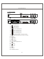
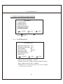
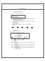
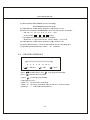
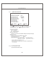
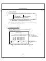
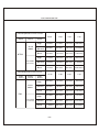
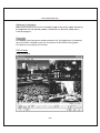
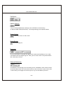
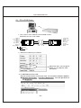
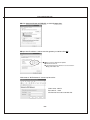
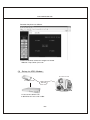
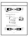
1
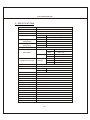
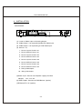
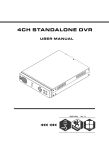
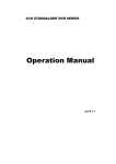
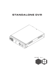
4CH STANDALONE DVR
四路單機數位錄影系統
USER MANUAL
2005 SEP.
4CH STANDALONE DVR
CONTENT
1、FEATURE
2
2、SPECIFICATIONS
3
3、INSTALLATION
4
4、FRONT PANEL
5
5、OPERATING MANUAL
6
6、VIEW CONTROL
11
7、PLAYBACK CONTROL
11
8、RECORD CONTROL
12
9、NTSC/PAL SETUP
12
10、Keypad Lock-up Setup
12
11、4 CHANNEL RECORDING HOURS
12
12、DVR Viewer User Guide
14
13、Video Server Board Installation (Option) 19
14、SXGA CARD FOR DVR USER MANUAL (Option) 25
-1-
4CH STANDALONE DVR
1、FEATURE
1、Definitely Standalone.
2、Real Time Refresh Rate.
3、Display While Recording.
4、Frame Recording & Quad Recording.
5、Compatible of NTSC/PAL format.
6、Advanced MJPEG.
7、Manual / Motion / Programmed / Sensor Recording.
8、4 Sensor by Time / Date.
9、Search by Time / Date.
10、Watch dog feature.
11、HDD Volume Indicator.
12、Can use USB to link PC, Player can search Time to Play、
saving and take photos functions.
13、Internal motion detect feature.
14、Auto switching function.
15、Looping Output.
16. Keypad Lock-up function.
-2-
4CH STANDALONE DVR
2、SPECIFICATIONS
OPERATION SYSTEM
Embedded RTOS
Video Input
NTSC/PAL
Video Input Channel
4CH Composite
Video Output Channel
Display Frame
Recording Frame
2CH Composite (VCR OUT / MONITOR OUT)
120 fps (4x30 fps)
NTSC
PAL
100 fps (4x25 fps)
NTSC
Max . 30 fps
Max. 25 fps
Rate(QUAD)
PAL
Recording Frame
NTSC
M a x. 7.5fps(30 fps/4)
PAL
Max. 6.25fps(25 fps/4)
Rate(EACH)
Recording Mode
Continuous / Motion / Programmed/ Sensor
Display
NTSC
720x480
PAL
720 x 576
Recording
NTSC
640x224
Advanced
Low
12K Bytes / Frame
Normal
15K Bytes / Frame
High
20K Bytes / Frame
Resolution
PAL
Compression Format
MJPEG
HDD
400G X 2
Backup Device
Search
640x272
(Max)
VCR
Time / Date / Event
Mode
Full screen
YES
Sensor
4 Input / 1 Output
MOTION DETECT
YES
LOSS DETECT
YES
AUTO SWITCHING
YES
BUZZER OUTPUT
YES
Brightness adjust
YES
Contrast adjust
YES
USB Output
YES
Looping Output
YES
Keypad Lock-up
YES
System a monitor
Power recover auto restore record mode
Power supply
DC 12V / 4A(AC110V-240V 50/60HZ)
Dimension
430mm x 300mm x 48mm (W x D x H)
Weight
3.5KG
LAN
10/100M
-3-
4CH STANDALONE DVR
3、INSTALLATION
REAR PANEL
VGA
VCR
MONITOR
(6)
VIDEO
IP
INIT
LOOP OUT
(3) (2)
LAN
IN ALARM OUT
(1)
DC 12V
(4)
(7)
(1) Cameras Video Input and Looping Output.
(2) Video Output : Corresponding to Monitor Video Input.
(3) Video Output : Corresponding to VCR Video Input.
(4) Sensor I / O:
1、Sensor Input of Camera #1
2、Sensor GND of Camera #1
3、Sensor Input of Camera #2
4、Sensor GND of Camera #2
5、Sensor Input of Camera #3
6、Sensor GND of Camera #3
7、Sensor Input of Camera #4
8、Sensor GND of Camera #4
9、Relay COM Output
10、Relay N/O Output
(5)Power Input : Please use the power supply attached
Adaptor : DC-12V / 4A
(6) VGA Output : Connect to VGA Monter ( o p tion )
(7)Ethernet RJ-45 ( o p tion )
-4-
(5)
4CH STANDALONE DVR
4、FRONT PANEL
(1) (2) (3)
TYPE A
(4)
( 5)
( 6)
(7)
(8)
(9)
( 10) ( 11) (12) (13)
USB
( 19 )
TYPE B
(14)
( 20 )
USB
(1)
Record Indicator
(2)
HDD #1 Indicator
(3)
HDD #2 Indicator
(4)
Camera #1 Display (Ch1)
(5)
Camera #2 Display (Ch2)
(6)
Camera #3 Display (Ch3)
(7)
Camera #4 Display (Ch4)
(8)
Quad Display (QUAD)、AUTO SWITCHING
(9)
MENU, Percentage of the Hard Drive recorded
(10)
UP
(11)
DOWN
(12)
SELECT
(13)
RECORD
(14)
PAUSE, Keypad Lock-up
(15)
RF
(16)
STOP
(17)
PLAY
(18)
FF
(19) USB Port
(20) HDD RACK (TYPE B)
-5-
(15) (16)
(17)
(18)
4CH STANDALONE DVR
5、OPERATING MANUAL(MAIN MENU)
MAIN MENU
SYSTEM SETUP
CAMERA SETUP
RECORD SETUP
RECORD SCHEDULE
HARD DRIVE SETUP
SYSTEM RESTORE
(
) : SELECT
Press
Press
(
):SET
(
to select items, use
to exit
):EXIT
to enter.
5-1 、SYSTEM SETUP
SYSTEM SETUP
BUZZER ALARM TIME
SENSOR ALARM TIME
LOSS ALARM
MOTION ALARM
SENSOR ALARM
PASSWORD SETUP
TIME SETUP
:02 S
:05 S
:ON
:ON-OFF
:ON
(
):SET
) : SELECT
(
(
):EXIT
(1)Buzzer Alarm Time Setup: 1-30 sec.
(2)Sensor Alarm Time Setup: 0-30 sec, CONT (Continue).
(3)Loss, Motion, Sensor Alarm:ON/OFF.
(4) Motion Alarm:ON-OFF(4 Type) ,front is Alarm, behind
is jump to alarm a picture.
-6-
4CH STANDALONE DVR
5-1-1 、PASSWORD SETUP
Select this item to change password :
OLD PASSWORD
:______
NEW PASSWORD
:______
PASSWORD CONFIRM :______
(1) When the new password is accepted, the board will flash the
following screen message.
“ PASSWORD CHANGING ”
(2) If the password was not accepted, you will receive a message
that inform you.
“ INCORRECT ”
* Use the view control button on the front panel to input
the umber.
is:" 1"
is: "2"
is:"3"
is: " 4"
is:"5"
5-1-2 、TIME SETUP
Select this item to set up current time.
TIME SET
2004/12/17 18:00:30
SHOW : UP 1
(
) : SELECT
* Press
Press
(
):SET
(
):EXIT
to setup time. Use
to increase value.
to exit and to save data.
Show Time setup:
UP 1 : Displayed on up-right corner of screen, date & time listed
in a rows.
UP 2 : Displayed on up-right corner of screen, date & time listed
in two rows.
DOWN1 : Displayed on down-right corner of screen, date & time
listed in a rows.
DOWN2 : Displayed on down-right corner of screen, date & time
listed in two rows.
-7-
4CH STANDALONE DVR
5-2 、CAMERA SETUP
CAMERA SETUP
CAMERA
RECORD SETUP
BRI SETUP
CON SETUP
SENSOR SETUP
MOTION SETUP
SENSITIVITY SETUP
AUTO SWITCHING
:CH1
:ON
:05
:05
:N-O
:ON
:05
:05 S
(
): SET
(
):SELECT
Press
Press
(
):EXIT
to select items. Use
to change data.
to exit and to save data.
(1)Camera select (default value Ch1).
(2)Record Set up : yes or no record.
(3)Brightness / Contrast Set up : default value is 5.
(4)Sensor Setup: Three items, N-O (normal-open),
N-C(normal-close), ----(not installed).
(5)Motion Set up : motion detector, ON/OFF.
(6)Sensitivity Set up : sensitivity setup of motion detector.
(7) AUTO SWITCHING : Switching time set up.
5-3 、RECORD SETUP
RECORD SET
RECORD SETUP
VIDEO QUALITY
RECORD FRAME RATE
SENSOR REC. FRAME RATE
SENSOR RECORD TIME
(
) : SELECT
(
):SET
-8-
:EACH MODE
:NORMAL
:30 fps
:15 fps
:05 SEC
(
):EXIT
4CH STANDALONE DVR
(1) Record Setup:EACH MODE (frame recording),
QUAD MODE (quad recording).
(2) Video Quality: video quality selection: High, Normal, Low
(3) Record Frame Rate: QUAD MODE frame rate alternatives as follows:
→30、20、15、10、7.5、6、5、4、3、2、1 fps.
→In this mode
、
、
、
invalid.
Each Mode frame rate alternatives as follows:
→Maximum : 7.5 fps each camera Totally :30 fps = 7.5 x 4 CH
(4) Video Quality: video quality selection: High, Normal, Low
(5) Sensor Record Time : maximum 60 seconds sensor recording time.
※(4)(5) Record Schedule only valid in “ S ” selection.
5-4 、RECORD SCHEDULE
RECORD SCHEDULE
TTTTTTTTTTTTTTTTTTTTTTTT
:
:
:
:
:
:
:
:
0
3 6 9 12 15 18 21
(
Press
Press
(1)Use
):SELECT
(
): SET
to select items. Use
to exit and to save data
(
): EXIT
to change record mode.
to change record mode.
(2)Range: 0-24 hrs.
(3)Set “T” for continuous recording.
(4)Set “S” for sensor recording. Please refer to 5-3 sensor setup.
(5)Set up “ - ” to disable the record time.
-9-
4CH STANDALONE DVR
5-5、 HARD DRIVE SETUP
HARD DRIVE SETUP
OVERWRITE ENABLED
MASTER HDD SIZE
MASTER HDD USED
MASTER HDD FORMAT
SLAVE HDD SIZE
SLAVE HDD USED
SLAVE HDD FORMAT
(
):SELECT
(
(YES )
80000MB
0MB0 %
N/A
N/A
): SET
(
): EXIT
Press
to select items. Use
to change data or to
execute function. Press
to exit and to save data.
(1)Overwrite Enabled
YES : Overwrite.
NO : Stop Recording.
(2)Master HDD Status
Indicates use of the master HDD including volume & percentage
(3)Master Format
Select this item to format HDD, screen show:
PASSWORD INPUT (6) ------ 6 digits.
If password correct, the screen shows : “ password correct “
Otherwise, it shows: “ password incorrect “
* Factory default password:111111
* HDD must be formatted before installation, replacement &
re-installation.
5-6、SYSTEM RESTORE
System Restore default value.
-10-
4CH STANDALONE DVR
6、VIEW CONTROL
(1)Can use the following view control to monitor images from cameras.
Camera #1 (Ch1)
Camera #2 (CH2)
Camera #3 (Ch3)
Camera #4 (CH4)
QUAD Display,Auto switching function.
(2)Prior to view control, HDD must be formatted. Either “EACH MODE”
or “QUAD MODE” should be selected. (Refer to 5-3)
(3)In mode of “QUAD MODE”, view control is only for quad display not
available for CH1, CH2, CH3, Ch4
7、PLAYBACK CONTROL
(1)Press , and the system shows the recorded period.
(2)Each period is as four hour
SEARCH TIME
HARD DRIVER: MASTER
04/04/01 02:47:56 - 04/04/01 02:47:56
01 TIME
02 TIME
03 TIME
(
(
Press
Select HDD
Select Start Date/
Time to End Date/Time
2004/12/10 02:47:50
2004/12/10 02:47:50
2004/12/10 02:47:50
):SELECT (
)EXIT (
)SET (
)PLAY
)SELECT EVENT/TIME
to select EVENT or DATE / TIME , Press
-11-
Event record
start Date/Time
to exit.
4CH STANDALONE DVR
(1)EVENT :
Press
choose one period, then press
to play.
(2)DATE / TIME :
The signal ”>” goes up to the “HARD DRIVER: MASTER”. Press
to select items. Use
select to change data, Then press
to play.
(3)PLAYBACK :
* Press
to speed forward. Continue to press
and show
x2、x4、x8 multiple playing.
* Press
to show x2 multiple back motion.
* Press
to pause.
* Press
to stop.
8、RECORD CONTROL
(1)Press
to start recording.
White
indicates recording.
(2) During recording, the mark ” * ” appears in status of overwriting
9、NTSC / PAL SYSTEM SETUP
(1) Replace the jumper to change system.
(2) J1 as follows:
PAL
J1
NTSC
10.Keypad Lock-up Setup:
Strike the button "pause" five times continually, "L" pops up on the left, to enable .
Keypad lock-up feature.
Strike the button "pause" five times again, "L" not found, to unlock keypad.
11. 4CH Recording Hours on 80GB Hard Drive
*Thereinafter a rough estimate a table for reference only, recording data
quantity can follow an image a variation a rate somewhat different.
-12-
4CH STANDALONE DVR
Recording Results in NTSC Format
Video
Signal
Display
Format
QUAD
MODE
NTSC
EACH MODE
(Full Screen)
30 fps
15 fps
7 fps
1 fps
Video
Quality
High
36Hours
72 Hours
144 Hours
1,080 Hours
Normal
48 Hours
96 Hours
192 Hours
1,440 Hours
Basic
58 Hours
116 Hours
232 Hours
1,740 Hours
High
64 Hours
128 Hours
256 Hours
1,920 Hours
Normal
90 Hours
180 Hours
360 Hours
2,700 Hours
448 Hours
3,360 Hours
Basic
112 Hours
224 Hours
Recording Results in PAL Format
25 fps
Video
Signal
Display
Format
QUAD
MODE
12 fps
6 fps
1 fps
Video
Quality
High
38 Hours
76 Hours
152 Hours
950 Hours
Normal
48 Hours
96 Hours
192 Hours
1,200 Hours
Basic
60 Hours
120 Hours
240 Hours
1,500 Hours
High
62 Hours
124 Hours
248 Hours
1,550 Hours
Normal
90 Hours
180 Hours
360 Hours
2,250 Hours
Basic
118 Hours
236 Hours
472 Hours
2,950 Hours
PAL
EACH MODE
(Full Screen)
-13-
12.DVR Viewer User Guide Revision V1.0.N.EN
Introduction
This document is the Operation Manual for DVR Viewer. The application will show
you stream image stored in the HDD which was previously formatted and recorded
by the DVR.
If any DVR HDD is connected to your PC, the application will automatically detect
the HDD and show the recorded stream. You can also save the current screen to a
BMP file, and save the current stream to a MYS stream file or an AVI file.
The application consists of two functional modules:
◆ DVR HDD PC Viewer
Shows stream stored in the HDD directly.
◆ MYS File Player
Plays captured stream MYS file.
Document History
◆ V1.0
Requirement
◆ OS
Windows 2000 / XP or later
◆ DirectX
DirectX 7.0 or later
Recommendation
◆ CPU
1.0 GHz or Higher
◆ RAM
256 MB or Greater
Installation
Hardware Installation
As stated above, the application shows stream which is stored in DVR HDD.
Before installing and executing the application, make sure that you connected DVR
HDD to the IDE cable of your PC directly, or via USB HDD adaptor
-14-
4CH STANDALONE DVR
Software Installation
Make sure that the OS of your PC is Windows 2000 or later [XP or 2003]. Otherwise,
the application will not operate properly. Double click on the DVR_Setup.exe to
install the program.
Execution
Just double click the shortcut of the execution file. The application first detects
physical HDDs installed at your PC and search for DVR HDD among them.
This process may take up to 1 minute.
DVR Viewer
User Interface
-15-
4CH STANDALONE DVR
Functions
Valid Stream Region Indication
Once a DVR HDD is selected, the application detects valid stream region where valid
video stream resides. You can drag this to access the whole streams of the DVR HDD.
Direct Access
If the stream stored in a DVR HDD is quite long, you may have difficulty to find the
exact scene you want to see. When you find a scene you would like to show your
friend or report to police officers later, please remember the number in the Direct
Access Input edit box, so that you can go there directly by entering the number in
the edit box and pressing “GO” button besides it.
Events List Button
You can access the latest 64 events and go to the event directly by this button.
-16-
4CH STANDALONE DVR
Configure
Options Button
You can change application settings such as MYS file save directory,
or default video mode (NTSC/PAL). To change setting, press Options button
Status Button
Show the status on the screen.
Reset Button
Reset the program.
Playback
Once a DVR HDD is selected, the application automatically displays first screen
recorded at the very beginning of it. Then, you can see stream at anywhere within
the valid stream reason.
Channel Selection
The default screen display channel setting is ALL CHANNEL, which shows all four
channel (if the stream has 4 channel streams) at the same time. If you want to see
a channel only or enlarge one channel, press any channel button you want.
-17-
4CH STANDALONE DVR
HDD Selection
Once the application detects one or more DVR HDDs, it automatically selects the
first DVR HDD. You can select any DVR HDD [the DVR HDDs are marked as "VY HDD ".
However, you cannot select the normal HDD, which may be Windows-formatted one.
Capturing Button
Screen Capturing
If you want to capture, or backup, current screen, press Capture Current Screen
button. Then it will capture the current screen and saves it as BMP file.
Stream Capturing Button
If you wan to capture, or backup, current stream, press Capture Current Stream
button.Then it will record the stream you want. It will create .MYS file, whose format
is Vineyard Technologies’ proprietary stream file format. You can play the recorded
file using MYS file player.
Stream Capturing Button
If you wan to capture, or backup, current stream, press Capture Current Stream button.
Then it will record the stream you want. It will create .AVI file. You can play the recorded
file using any player which support AVI file.
MYS File Player
You can play the recorded MYS file using MYS file player.
-18-
13. Video Server Board Installation (Option)
Illustration:
P10
1.Stop the power supply.
2.Remove the cross piece from LAN port.
3.Put the video server board against the LAN port.
4.Fix the board with the screws.
5.Pull out the cable P3 from mother board and slot it in P1 on video server board.
6.Slot one end of IDC-20P cable in P2 on video server board , the other end in
P3 on mother board.
7.Slot an other cable one end in P4 on video server board , the other in P10 on
mother board.
-19-
4CH STANDALONE DVR
DVR LAN Functional Specification
Network Interface
LAN Connector
Protocol
Link Me thod
10/100 Base T,Ethernet
RJ-45
HTTP,TCP/IP,UDP,ICMP,ARP,BPDU
ADSL, ISDN, LAN, Internet / Intranet
Remo te Control
Live ima ge、playback、set me nu、record
Remo te Access
Standard Browser : Mi crosoft IE Browser / Netscape Browser
with JAVA Support.
( 1)、TCP/IP Port as diagram below :
CH3
CH4
IP
INIT
G
1
G
2
IN
G 3
LAN
G
ALARM
(4)
4
C
NO
OUT
(3) (2)
(1)
1.Ethernet RJ-45
2.100Mbps/link/Active indicator. (orange)
3.10Mbps/link/Active indicator. (green)
4.IP-INIT SETUP : 192.168.0.100 the default IP for initialization
(IP INIT)
a.As shown jumper is to be
on the left
b.How we initialize the IP?
1.Put the jumper to the right.
2.Reboot the DVR.
3.Put the jumper to the left again.
-20-
4CH STANDALONE DVR
(2)、PC to DVR Setup :
1. Use a cross-over cable to connect DVR and PC.
Definition of cross-over cable:
Brown
Brown/White
Green
Blue/White
Blue
Green/White
Orange
Orange/White
8
7
6
5
4
3
2
1
1
2
3
4
5
6
7
8
Green/White
Green
Orange/White
Blue
Blue/White
Orange
Brown/White
Brown
COLOR
PIN#
2. Default IP and other parameters.
Above two items are changed IP
Routor or not subject to router
parameters.
3. IP AMENDED ON PC SIDE.
Domain of DVR and PC must be the same. For example of windows 2000/XP:
◆ Network Connections→Local Area Connection,Click the right button to
find Properties.
-21-
4CH STANDALONE DVR
◆Click Internet Protocol (TCP/IP) and click Properties.
◆Input the IP address ,subnet mask & gateway as below click OK.
◆Wait until data updated completed.
◆Execute IE browser.
◆Input the following IP address to start connection.
Http://192.168.0.100
Welcome to "DVR Network" comes up hereafter.
Username:admin
Password :1234
Click enter fo access remote site.
-22-
4CH STANDALONE DVR
Remote site picture as follows.
※Download JAVA software if images not found.
Website http://www.java.com
(3)、Setup via ADSL Modem :
61.222.12.123
12.234.123.123
Internet
1.Cross over cable in use.
2.definition of cross-over cable:
-23-
4CH STANDALONE DVR
Brown
Brown/White
Green
Blue/White
Blue
Green/White
Orange
Orange/White
8
7
6
5
4
3
2
1
1
2
3
4
5
6
7
8
Green/White
Green
Orange/White
Blue
Blue/White
Orange
Brown/White
Brown
COLOR
PIN#
3.Prior to installation,IP address setup must be well done.
(4)、Connection Via Router or Hub.
IP Router
Gateway
192.168.0.1
12.234.123.123
61.222.12.123
Internet
Port 80 →192.168.0.100
Port 81 →192.168.0.101
◆Setup procedure same as previous description.
◆In use of Router , distributor and Hub.
◆We connect DVR & devices above with the cable as follows:
Brown
Brown/White
Green
Blue/White
Blue
Green/White
Orange
Orange/White
8
7
6
5
4
3
2
1
1
2
3
4
5
6
7
8
-24-
Orange/White
Orange
Green/White
Blue
Blue/White
Green
Brown/White
Brown
14. SXGA CARD FOR DVR (Option)
∣、 Feature:
1.SXGA 1280*1024 High Resolution.
2.Supports LCD/CRT/Projector/Plasma TV.
3.Plug & Play free from driver & software.
4.NTSC/PAL jump swappable.
5.On Screen Display(OSD).
Ⅱ、Specification:
Signal input : digital signal input to DVR.
Signal output : VGA monitor output.
Power input : DC +5V from DVR.
Power consumption : 800mA.
Ⅲ、System Requirement:
LCD/CRT monitor with VGA input.
Projector with VGA input.
Ⅳ、Guideline on keypad:
1.
2.
3.
4.
5.
+
: entrance of VGA menu setup.
: exit.
: left/decrease.
: right/increase.
: swap/enter.
Ⅴ、Instruction:
The initial display on VGA monitor
OUTPUT TIMING
Press ENTER to setup
15 : 1280 x 1024@60Hz ?
1280 x 1024@60Hz
1.
2.
3.
4.
5.
OUTPUT TIMING: Resolution and Frequency Adjustment.
H ZOOM: Horizontal Zoom.
H PHASE: Horizontal Phase.
V ZOOM: Vertical Zoom.
V PHASE: Vertical Phase.
-25-
4CH STANDALONE DVR
#Press Menu and Pause to enter VGA.
#Press to move left and right setup menu.
#Press enter to swap decrease and increase feature.Press to decrease and increase.
#Press enter again to left and right feature or to confirm setup.
#Press Menu to exit VGA setup menu ,for DVR operation.
Ⅵ、Installation:
Procedure:
1.Uncover DVR.
2.Remove the block behind DVR.
3.Remove the connector linking to control board.
4.Unfasten two screws as diagram.
5.Mount two copper bolts on the cabinet bottom.
6.Connect motherboard and VGA board with two cables of 20pin IDC.
7.Insert VGA Card.
8.Fasten VGA connector screws.
9.Fasten VGA Card screws.
10.Plug in connector to VGA Card.
11.Connect to VGA monitor.
12.Test if VGA monitor works.
13.Put the DVR cover on the cabinet if ok.
14.Enter menu to get proper setup.
15.Done
P5
-26-