1
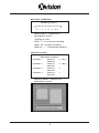
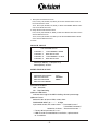
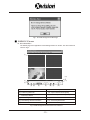
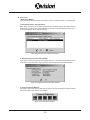
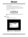
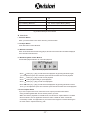
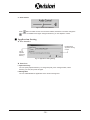
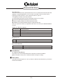
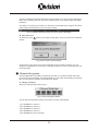
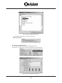
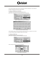
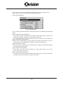
4 Channel
Standalone DVR
USERS MANUAL
CONTENT
FEATURE
1
FRONT PANEL
1
REAR PANEL
2
CONTROL PANEL BUTTON
3
SPECIFICATIONS
5
OPERATING MANUAL
6
VIEW CONTROL
10
PLAYBACK CONTROL
10
RECORD CONTROL
11
4 CHANNEL RECORDING HOURS
11
DVR PC VIEWER
12
REMOTE DVR CLIENT
19
ALARM & LOOPING CABLE
31
■ FEATURE
1、 Definitely Standalone.
2、 Real Time Refresh Rate.
3、 Display While Recording.
4、 Frame Recording & Quad Recording.
5、 Support Audio Recording.
6、 Small Size Design.
7、 Anti-Shock HDD Mobile Rack.
8、 Advanced MJPEG.
9、 Manual / Motion / Programmed Recording.
10、 Search by Time / Date.
11、Watch dog feature.
12、HDD Volume Indicator.
13、Internal motion detect feature.
14、Auto switching function.
■ FRONT PANEL
Removable HDD RACK
.1.
■ REAR PANEL
VIDEO OUT
AUDIO
MONITOR
VIDEO IN
CH1
CH3
CH2
CH4
IN
DC12~24V
VCR
★
OUT
The standard for car usage
VIDEO OUT
AUDIO
MONITOR
VIDEO IN
CH1
CH3
CH2
CH4
IN
DC12V
ALARM I/0
USB
◆
VCR
VIDEO LOOP
OUT
The standard for home usage
VIDEO OUT
AUDIO
MONITOR
LAN
VIDEO IN
CH1
CH3
CH2
CH4
IN
DC12~24V
ALARM I/0
USB
●
VIDEO LOOP
VCR
The advanced for home usage
.2.
OUT
■ CONTROL PANEL BUTTON
CONTROL BUTTONS in the VIEW MODE
Menu: Enter the MENU MODE for the system setup.
(Recording and Playback needs to be stopped before entering the MENU MODE)
Record: Activate the recording.
Play: Playback the latest video stream which you haven't seen before.
Auto Switching Channels: Enable / Disable the auto switching function.
Quad Display: Monitor will be displayed as a quad display.
Channel 1: Channel 1 will be displayed as full screen.
Channel 2: Channel 2 will be displayed as full screen.
Channel 3: Channel 3 will be displayed as full screen.
Channel 4: Channel 4 will be displayed as full screen.
CONTROL BUTTONS in the RECORD MODE
HDD USAGE: Show the usage of the hard drive.
Key lock: Push the button 5 times to lock/unlock the “STOP RECORDING” key.
(While the “STOP” Key is locked, there will be a letter “L” showed on the left-down corner)
Stop: Stop the recording.
Auto Switching Channels: Enable / Disable the auto switching function.
Quad Display: Monitor will be displayed as a quad display.
Channel 1: Channel 1 will be displayed as full screen.
Channel 2: Channel 2 will be displayed as full screen.
Channel 3: Channel 3 will be displayed as full screen.
Channel 4: Channel 4 will be displayed as full screen.
CONTROL BUTTONS in the MENU MODE
Save Setup: This button needs to be pressed to save all the setting information and exit
the setup pages after each setup is finished.
Select: Confirm the selection made or setting items.
UP: UP button for item selection.
RIGHT: RIGHT button for item selection.
Select: Confirm all the selection made or setting items
DOWN: DOWN button for item selection.
LEFT: LEFT button for item selection.
Save Setup: Save the setting information and exit the setup pages.
.3.
CONTROL BUTTONS in the PLAY MODE
Search Mode: Enter the PLAYBACK EVENTS SEARCH MODE.
Play: Play the video stream in normal speed.
Pause: Pause the playing.
Stop: Stop the playing, and go back to the VIEW MODE.
Channels Switching: Switch CH1→CH2→CH3→CH4 as full screen and press again
to show the quad display.
Forward Fast: There are 3 speeds for fast forward. (Ff1→ Ff2 → Ff3)
Steps Play: Play the video stream frame by frame.
Rewind Fast: Rewind Fast function.
CONTROL BUTTONS in the PLAYBACK EVENTS SEARCH MODE
Exit: Go back to the VIEW MODE.
Play: Playback the selected stream in normal speed.
Search Mode Switch: Switch between the TIME SEARCH MODE and the EVENTS
SEARCH MODE.
Select: Confirm the selection made or setting items.(TIME SEARCH MODE)
UP: UP button for item selection.
RIGHT: RIGHT button for item selection.
DOWN: DOWN button for item selection.
Select: Confirm the selection made or setting items. (TIME SEARCH MODE)
LEFT: LEFT button for item selection.
.4.
■ SPECIFICATIONS
NTSC
Video Input
PAL
4CH Composite
Video Input Channel
2CH Composite (VCR OUT / MONITOR OUT)
Video Output Channel
120 fps (4x30 fps)
100 fps (4x25 fps)
Recording Frame Rate(QUAD)
Max . 30 fps
Max. 25 fps
Recording Frame Rate(EACH)
M a x. 7.5fps(30 fps/4)
Max. 6.25fps(25 fps/4)
Display Frame
Recording Mode
Resolution
Continuous / Motion / Programmed
Display
720x480
720 x 576
Recording
640x224
640x272
Compression Advanced
MJPEG
Format
Low
12K Bytes / Frame
Normal
15K Bytes / Frame
High
20K Bytes / Frame
HDD
Max. 400GB
Audio Functions 1CH Audio Input/Output Real Time Recording And Playing
Search
Mode
Time / Date / Events list
4CH motion detect
Moition Detect
Video loss display
YES
Auto ch_switching
YES
Buzzer Output
Video loss,Motion,Sensor
Video adjust
Brightness,Contrast,Color
195mm x 265mm x 65mm (W x D x H)
Dimension
4ch sensor input /1ch alarm output
Alarm interface
◆ ●
Looping interface
◆ ●
4ch looping video output with 75 Ohm
USB interface
◆ ●
USB 2.0 H.D. Backup
LAN interface
Power type
Weight
●
(N.O,N.C Max:AC120V /0.5A)
MPG4 video output and DVR control
★
DC 10V ~DC26V /about 15W( add HD)
◆ ●
★ ◆
About 2.8KG
●
About 2.9KG
DC 12V±0.5V /about 15W( add HD)
★ The standard for car usage
◆ The standard for home usage
● The advanced for home usage
.5.
■ OPERATING MANUAL (MAIN MENU)
MAIN MENU
●
◆
SYSTEM SETUP
CAMERA SETUP
RECORD SETUP
RECORD SCHEDULE
MOTION SETUP
SENSOR SETUP
HARD DRIVE SETUP
NETWORK SETUP
SYSTEM RESTORE
PRESS(UP,DOWN), THEN(SELECT)
PRESS(MENU) TO EXIT
◆ For the standard for home usage only
● For the advanced for home usage only
SYSTEM SETUP
SYSTEM SETUP
:〔PAL〕
:
2
: 〔ON〕
:〔OFF〕
:〔OFF〕
:
1
SYS T EM STANDARD
BUZZER ALARM TIME
LOSS ALARM
AUDIO RECORD
AUDIO MUTE
AUDIO CHANNEL
PASSWORD SETUP
TIME SETUP
PRESS(UP,DOWN), THEN(SELECT)
PRESS(MENU) TO EXIT
PASSWORD SETUP
Select this item to change password :
CURRENT PASSWORD
NEW PASSWORD
CONFIRM PASSWORD
:______
:______
:______
(1) When the new password is accepted, you will receive a message
that inform you.
“ PASSWORD CHANGED ”
(2) If the password was not accepted, you will receive a message
that inform you.
“ NO PASSWORD CHANGED ”
*Use the view control button on the front panel to input
the umber.
.6.
is: " 1"
is: " 2"
is:" 3"
is: " 4"
is: "5"
TIME SETUP
Select this item to set up current time.
TIME SET
2004/12/17 18:00:30
PRESS(REW,FF), THEN(SELECT)
PRESS(MENU) TO EXIT
CAMERA SETUP
CAMERA SETUP
CAMERA
LIVE ON/OFF
RECORD O N/ OFF
BRI GHT SETUP
CON TRAST SETUP
COLORS SETUP
AUTO SWITCHING
: CH1
: ON
: ON
: 5
: 5
: 5
: 2
PRESS(UP,DOWN), THEN(SELECT)
PRESS(MENU) TO EXIT
RECORD SETUP
RECORD SET UP
RECORD SETUP
VIDEO QUALITY
RECORD FRAME RATE
:EACH
:NORMAL
:30
PRESS(UP,DOWN), THEN(SELECT)
PRESS(MENU) TO EXIT
(1) Record Setup:EACH MODE (frame recording),
Each Mode frame rate alternatives as follows:
Maximum : 7.5 fps each camera Totally :30 fps = 7.5 x 4 CH
QUAD MODE (quad recording).
In this mode
、
、
、
invalid.
(2) Video Quality: video quality selection: High, Normal, Low
(3) Record Frame Rate: QUAD MODE frame rate alternatives as follows:
Enable Audio Record → 30、15、10、7、5、4、3、2、1 fps.
Disable Audio Record → 30、15、10、7、5、4 fps.
.7.
RECORD SCHEDULE
RECORD SCHEDULE
TTTTTTTTTTTTTTTTTTTTTTTT
:
:
:
:
:
:
:
:
0
3 6 9 12 15 18 21
PRESS( REW,FF), THEN(SELECT)
PRESS(MENU) TO EXIT
(1)Range: 0-24 hrs.
(2)Set “T” for continuous recording.
(3)Set “M” for motion recording.
(4)Set up “ - ” to disable the recording.
MOTION SETUP
MOTION SETUP MENU
CHANNEL-1
CHANNEL-2
CHANNEL-3
CHANNEL-4
SENSITIV
AREA SET
SENSITIV
AREA SET
SENSITIV
AREA SET
SENSITIV
AREA SET
0
(OFF)
0
(OFF)
3
.
5
.
PRESS(UP,DOWN), THEN(SELECT)
PRESS(MENU) TO EXIT
MD CH 1 BLOCK 1
1
2
(UP,DOWN,FF,REW)MOVE (MENU)EXIT
(SELECT)SET UPPER-LEFT POINT
.8.
1. Setup the First Detective Area
First, Press (UP, DOWN, FF, REW ) to Set the UPPER-LEFT Point of
the First Detective Area.
Then, Press (UP, DOWN, FF, REW ) to Set the DOWNER-RIGHT Point
of the First Detective Area.
2. Setup the Second Detective Area
First, Press (UP, DOWN, FF, REW ) to Set the UPPER-LEFT Point of the
Second Detective Area.
Then, Press (UP, DOWN, FF, REW ) to Set the DOWNER-RIGHT Point
of the Second Detective Area.
3.Finish.
SENSOR SETUP
H/W SENSOR SETUP
CHANNEL-1
TYPY:NORMAL-OPEN
CHANNEL-2
NOT INSTALLED
CHANNEL-3
TYPY:NORMAL-CLOSE
CHANNEL-4
NOT INSTALLED
PRESS(UP,DOWN), THEN(SELECT)
PRESS(MENU) TO EXIT
HARD DRIVE SETUP
HARD DRIVE SETUP
OVERWRITE ENABLED
MASTER HDD SIZE
MASTER HDD USED
MASTER HDD FORMAT
(YES )
80000MB
0MB0 %
(1)Overwrite Enabled
YES : Overwrite.
NO : Stop Recording.
(2)Master HDD Status
Indicates the usage of the HDD including volume & percentage
(3)Master Format
Select this item to format HDD, screen show:
PASSWORD INPUT (6) ------ 6 digits.
If password correct, the screen shows :“ Password Correct“
“ Hard Disk Formatted“
Otherwise, it shows:“ Password Incorrect“
* Factory default password:111111
* HDD must be formatted before installation, replacement &
re-installation.
.9.
NETWORK SETUP
NETWORK MENU
ACCEPT CLIENT
MAC ADDRESS
IP ADDRESS
SUBNET MASK
GATEWAY
PORT NUMBER
( YES)
00:00:00:73:37:31
192.168.001.090
255.255.255.000
192.168.001.254
14337 14338
PRESS(UP,DOWN), THEN(SELECT)
PRESS(MENU) TO EXIT
SYSTEM RESTORE
System Restore t o the default value.
■ VIEW CONTROL
(1)You can use the following view control buttons to monitor the video from the cameras.
Camera #1 (Ch1)
Camera #2 (CH2)
Camera #3 (Ch3)
Camera #4 (CH4)
QUAD Display, Enable / Disable theAuto switching function.
(2)View Control is only valid while the RECORD MODE is in the EACH MODE.
■ PLAYBACK CONTROL
(1)Press
, and the system will play the latest event which you haven't seen before.
(2)Press
, and the system will enter the PLAYBACK EVENTS SEARCH MODE.
(3)Each period is as four hour
SEARCH TIME
04/04/01 02:47:56 - 04/04/01 02:47:56
01 TIME
02 TIME
03 TIME
2004/12/10 02:47:50
2004/12/10 02:47:50
2004/12/10 02:47:50
Selec t Start Date/
Time to End Date/
Time
(UP, DOWN) MOVE (PLAY) PLAY (MENU) EXIT
(STOP) SELECT MODE (SELECT) CHANGE
Press
Press
to switch between the TIME SEARCH MODE and the PLAYBACK
EVENTS SEARCH MODE,
to exit.
.10.
(1)EVENTS SEARCH MODE :
Press
choose one period, then press
to play.
(2)TIME SEARCH MODE :
The signal ”>” goes up to the “HARD DRIVER: MASTER”. Press
to select items. Use
select to change data, Then press
to play.
(3)PLAYBACK :
* Press
to speed forward. Continue to press
and show
FF(Fast Forward)1, FF2, FF3 playing.
* Press
to rewind the playback.
* Press
to pause.
* Press
to stop.
■ RECORD CONTROL
(1)Press
to start recording.
(2) During recording, the mark ” * ” appears in status of overwriting
■ 4CH RECORDING HOURS ON 80GB HARD DRIVE
*Thereinafter a rough estimate a table for reference only, recording data
quantity can follow an image a variation a rate somewhat different.
Re cording Re sults in NT SC Forma t
Video
Signal
Display
Format
Video
Quality
Hi gh
36Hours
QU AD
MOD E
Nor mal
48 Hours
Bas ic
58 Hours
116 Hours
232 Hours
1,740 Hours
Hi gh
64 Hours
128 Hours
256 Hours
1,920 Hours
NT SC
EA CH MODE
(Fu ll Sc reen)
30 fps
Nor mal
90 Hours
Bas ic
112 Hours
15 fps
7 fps
1 fps
72 Hours
144 Hours
1,080 Hours
96 Hours
192 Hours
1,440 Hours
180 Hours
224 Hours
360 Hours
2,700 Hours
448 Hours
3,360 Hours
6 fps
1 fps
Re cording Re sults in PA L Forma t
Vi deo
Si gnal
25 fps
12 fps
Di splay
Forma t
Vi deo
Qu ality
Hi gh
38 Hours
76 Hours
152 Hours
950 Hours
QU AD
MOD E
No rma l
48 Hours
96 Hours
192 Hours
1,200 Hours
PAL
EA CH MODE
(Fu ll Sc reen)
Basic
60 Hours
120 Hours
240 Hours
1,500 Hours
Hi gh
62 Hours
124 Hours
248 Hours
1,550 Hours
No rma l
90 Hours
180 Hours
360 Hours
2,250 Hours
Basic
118 Hours
236 Hours
472 Hours
2,950 Hours
.11.
DVR PC VIEWER
◆ For the standard for home usage only
● For the advanced for home usage only
Introduction
This document is the Operation Manual for the 4 CH Stand Alone DVR PC Viewer.
The application will show you stream image stored in the Storage Device (HDD, CF card, USB
Memory Stick, etc.), which was previously formatted and recorded by the DVR.
If any DVR-formatted Storage Device is connected to your PC, the application will automatically
detect the Storage Device and show the recorded stream. You can also save the current screen
to a JPEG file, and save the video/audio stream to a file [“MYS” file, the Vineyard's proprietary
video/audio stream file format.
The application consists of two functional modules:
DVR PC Viewer Shows stream stored in the DVR Storage Device.
MYS File Player Plays captured stream file.
Terms in This Document
Storage Device
Hard Disk, CF Card, USB Memory Stick
The Application
DVR Storage Device PC Viewer
DVR Storage Device Storage Device which was previously formatted and recorded by the
DVR base on Vineyard Technologies' DVR chip.
OS
Operating System
CPU
Central Processing Unit
RAM
Random Access Memory
GUI
Graphic User Interface
Requirement
OS
OS of your PC should be Windows 2000/XP or later.
DirectX
Your PC should be equipped with DirectX 7.0 or later.
Recommendation
Operating System (OS)
The application runs only on Windows 2000 or Later (XP, 2003).
CPU
1.0 GHz or Higher.
RAM
256 MByte or greater.
■ Installation
A. Hardware Installation
Before executing the application, connect the DVR Storage Device to the IDE cable of your
PC directly, or via USB adaptor
B. Software Installation
Run Setup.exe in the CD-ROM and follow the instruction to finish the installation.
[Make sure that the OS of your PC is Windows 2000 or later [XP or 2003].]
■ Execution
Just double click the icon of PC Viewer. The application will try to detect physical storage devices
installed at your PC and search for DVR storage device(s) among them.
If there is DVR Storage Device, the application will automatically start playing. However, If the
application fails to detect DVR Storage Device, which means that there is no DVR Storage
Device installed to your system, it will show following error message and set the default working
mode to MYS Player (See Section. 4).
.12.
Fig.1. No DVR Storage Device Message
■ DVR PC Viewer
A. User Interface
The default page of the application is DVR Storage Device PC Viewer. The user interface is
shown in Fig.2.
(1)
(12)
(11)
(2)
(3)
(4) (5)
(6)
(7)
(8)
(9)
(10)
(1) Screen
(7) PC Viewer Playback Control
(2) Positioning Slider Bar
(8) Capture Stream Button [MYS]
(3) MYS Player Button
(9) Screen Capture Button [JPEG]
(4) DVR Storage Device Change Button
(10) Audio Control
(5) DVR Storage Device Information
(11) Viewer Playback Mode
(6) Channel Selection
(12) Stream Time Display
Fig.2. DVR Storage Device PC Viewer User Interface
.13.
B. Functions
i. MYS Player Button
If you want to see MYS file which was stored in your PC, press this button or press [F2] key.
ii. DVR Storage Device Change Button
When there are more than one DVR storage devices, this button will be activated. Press this
button when you want to see video/audio stream stored in other DVR storage device. Fig.3
shows DVR storage device selection window.
Fig.3. DVR Storage Device Selection Window
iii. DVR Storage Device Information Button
If you want to know how big is the DVR storage device is, or how much stream data is stored
in the device, press this button. Fig.4 shows the DVR storage device information window.
Fig.4. DVR Storage Device Information Window
iv. Channel Selection Buttons
According to the record channel setting of the stream, each channel buttons will be enabled.
Select any channel you want to see enlarged.
Fig.5. Channel Selection Buttons
.14.
Press
button (or [ 5 or Numpad 5 ] Key) to see all 4 channels at the same time.
Press
button (or [ 1 or Numpad 1 ] Key) to see channel 1 enlarged.
Press
button (or [ 2 or Numpad 2 ] Key) to see channel 2 enlarged.
Press
button (or [ 3 or Numpad 3 ] Key) to see channel 3 enlarged
Press
button (or [ 4 or Numpad 4 ] Key) to see channel 4 enlarged.
v. Viewer Control Buttons
Use Viewer Control Buttons to control viewer playback.
Fig.6. Viewer Control Buttons
*Press
button (or [<-] Key) to start fast reverse playback. By pressing this button again,
you can adjust the speed. The maximum speed is 8 times faster than reverse playback.
*Press
button (or [<-] Key) to start reverse playback.
*Press
button (or [Space Bar]) to pause playback.
*Press
button (or [->] Key) to start normal playback.
*Press
button (or [->] Key) to start fast forward playback. By pressing this button several
times, you can adjust the speed. The maximum speed is 8 times faster than normal playback.
vi. Capture Stream Button
If you want to capture stream, follow the stream capture procedure listed below:
* Using “Positioning Slider Bar” find the stream position you want.
* Make sure that the playback is in PAUSE mode, and the Capture Stream Button is enabled.
* Press the button, then the application will start capturing. During capturing, Capturing
Indicator Window will be popped up.
Fig.7. Capturing Indicator Window
* To stop capturing, press “Stop Capturing” button on the window.
The captured file (an MYS file) will be stored in the “Capture Directory.” See the Application
Setting Section, to know more about the “Capture Directory” setting.
.15.
vii. Screen Capture Button
If you wan to capture the screen, follow the screen capture procedure listed below:
* Using “Positioning Slider Bar” find the stream position you want.
* Make sure that the playback is in PAUSE mode, and the Screen Capture Button is enabled.
* Press the button, then the application will start to make a JPEG file. When a JPEG file
successfully created. The application let you know that the image file is created showing
the file name and the “Capture Directory” path.
viii. Audio Control
Fig.8. Audio Control Buttons
Press
button to enable sound. Once sound is enabled, the button icon will be changed to
. Press it to disable sound again. Using the slider bar, you can adjust the volume.
■ MYS Player
A. User Interface
Fig. 9 shows the user interface of the MYS player.
(1)
(2)
(3)
(10)
(4)
(5)
(6)
(7)
.16.
(8)
(9)
(1) Screen
(6) MYS file information
(2) MYS File Select Dialog
(7) MYS File Playback Control
(3) Positioning Slider Bar
(8) Screen Capture Button [JPEG]
(4) PC Viewer Button
(9) Audio Control
(5) File Open Button
(10) Playback Status
Fig.9. MYS File Player User Interface
B. Functions
i. PC Viewer Button
When you want to back to PC Viewer function, press this button.
ii. File Open Button
Press this button to select MYS file.
iii. MYS file information
When an MYS file selected and being played, the file name and the file size will be displayed
in the MYS file information box.
iv. MYS file Playback Control Buttons
Use MYS file playback buttons to control the playback.
Fig.10. MYS file playback control Buttons
* Press
button (or [<-] Key) to start fast reverse playback. By pressing this button again,
you can adjust the speed. The maximum speed is 64 times faster than reverse playback.
* Press
button (or [<-] Key) to start reverse playback.
* Press
button (or [Space Bar]) to pause playback.
* Press
button (or [->] Key) to start normal playback.
* Press
button (or [->] Key) to start fast forward playback. By pressing this button several
times, you can adjust the speed. The maximum speed is 64 times faster than normal playback.
v. Screen Capture Button
If you wan to capture the screen, follow the screen capture procedure listed below:
* Using “Positioning Slider Bar” find the stream position you want.
* Make sure that the playback is in PAUSE mode, and the Screen Capture Button is enabled.
* Press the button, then the application will start to make a JPEG file. When a JPEG file
successfully created. The application let you know that the image file is created showing the
file name and the “Capture Directory” path.
.17.
vi. Audio Control
Fig.11. Audio Control Buttons
Press
button to enable sound. Once sound is enabled, the button icon will be changed to
. Press it to disable sound again. Using the slider bar, you can adjust the volume.
■ Application Setting
A. User Interface
Enable/Disable
Application Closing
Confirm
Change
Captured
File Saving
Directory
Fig.12. Application Setting Dialog
B. Functions
i. Capture Directory
You can specify Capture Directory. To change the path, press “Change” Button, select
directory you want, and press OK again.
ii. Message Box
You can enable/disable the application close confirm message box.
.18.
Remote DVR Client
● For the advanced for home usage only
Introduction
This document describes the operational behavior of the 4 CH Stand Alone Remote DVR Client
application. Using this application, you can access to your DVR, control it, and see what's
happening remotely. Moreover, you can capture the video on your PC.
The application consists of four main functions:
Remote Monitoring Shows incoming video/audio stream from your DVR.
Remote DVR Management Manage your DVR remotely.
Stream Capturing Captures incoming video/audio stream.
Playback for the Captured Stream Plays the captured stream file.
When you capture the stream, the application will create one stream (2YYYMMDDHHMMSS.
mys) file.
Terms in This Document
The Application
Remote DVR Client
OS
Operating System
CPU
Central Processing Unit
RAM
Random Access Memory
GUI
Graphic User Interface
Requirement
OS
OS of your PC should be Windows 2000/XP or later.
DirectX
Your PC should be equipped with DirectX 7.0 or later.
Recommendation
CPU
1.0 GHz or Higher.
RAM
256 MByte or greater.
■ Installation
A. Software Installation
Run Setup.exe in the CD-ROM and follow the instruction to finish the installation.
[Make sure that the OS of your PC is Windows 2000 or later [XP or 2003].]
.
■ Execution
Just double click the program icon. Then you will see a Remote Client Window. Fig.1 shows the
Remote Client Window.
.19.
Fig.1. Remote DVR Client
■ Connection
Before you connect to your DVR, make sure that your DVR is correctly configured for the
network connection. If your DVR is connected to the network and configured correctly, then you
can connect to your DVR now. For more information, please refer to DVR operation manual.
A. Connection
To connect to your DVR, you should know following information:
* The IP address of your DVR.
* The Password.
If you have the IP address and the password, press ! icon at the bottom of the application
(or press [Ctrl+C] key). Then you will see connection manager window.
Fig.1. Connection Window
NOTE. The IP address of your DVR will be different.
.20.
Type the IP address and Password and press Connect button. You can save the IP address for
future use by checking “Save IP.” Once an IP address saved, the IP address will be the default
IP address.
If the client is connected to your DVR, you will see the current DVR screen image on the screen
and the Status Window Show Current Connection Speed.
Fig.2. The Status Window [showing connection speed of 960 Kbps]
B. Disconnection
To disconnect, press ! button (or press [Ctrl+C] key) again. Then you will see the confirmation
window.
Fig.3. Disconnection Confirm Window
To disconnect, press “YES.” Press “NO” to maintain current connection. However, you can
configure the application not to show the confirmation window if you want. See Section 8.A.ii for
more information.
■ Channel Navigation
Once the application successfully connected to your DVR, you would see all four channels in
the screen (the channel display may differ depending on the record channel setting of the DVR).
Now, you can select a channel to see as full screen image.
A. Change Channel
Select one channel button shown in Fig.4.
Fig.4. Channel Navigation Buttons
You can also use keyboard to change view channel. The key is listed below.
* [1] or [NUMPAD 1] channel 1
* [2] or [NUMPAD 2] channel 2
* [3] or [NUMPAD 3] channel 3
* [4] or [NUMPAD 4] channel 4
* [5] or [NUMPAD 5] all four channels
.21.
■ Audio Control
A.Audio Sounding/Mute
Press
button, or press [Ctrl+M] Key, to activate audio when the client is connected to the
DVR or the client is playing pre-recorded stream file.
Press
button, or [Ctrl+M] Key to deactivate audio.
B.Volume Control
To adjust audio volume, use the audio volume slider or use [Up] and [Down] Key as well.
■ DVR Control
You can make your DVR state to start/stop recording and start/stop playback remotely. DVR
control buttons are shown in Fig.5.
DVR Control
Fig.5. DVR Control Buttons
A. Recording
Press
button (or press [Ctrl+Shift+R] key) to make your DVR start recording. Then you will
see recording status on the Status Window. The Status Window will indicate the current status
of your DVR as in Fig.6.
Fig.6. The Status Window [DVR Recording State]
Press
button (or press [Ctrl+Shift+S] key) to make your DVR top recording.
B. Playback
If you want to start DVR playback, press
button (or press [Ctrl+Shift+P] key) to get recorded
event log. The client will receive event log from your DVR and show you the list. Fig.7 shows the
DVR Event Log.
Fig.7. DVR Event Log.
.22.
There are two options for starting DVR playback.
i. Timed Play
The upper part of the window shows the time range of the stream stored in the DVR HDD.
You can specify the time when you are interested in. Fig.8 shows timed play.
Fig.8. Timed Play Window
ii. Event Play
The lower part of the window is event list. To see an event, select the event and double click
it or press “Start Event Play” Button.
Fig.9. Event Play Window
Once DVR play starts, the Status Window will show your DVR is now playing.
Fig.10. Status Window [DVR Play]
iii. Playback Buttons
Press
button (or press [Ctrl+Shift+F] key) to start Fast Forward. [FF1 -> FF2 ->FF3 -> Ff1]
Press
button (or press [Ctrl+Shift+V] key) to start Fast Rewind.
Press
button (or press [Ctrl+Shift+U] key) to pause the playback.
Press
button (or press [Ctrl+Shift+P] key) again to resume play when DVR is in FF,REW
or PAUSE.
Press
button (or press [Ctrl+Shift+S] key) to stop playback.
■ PC Capturing
You can capture incoming video/audio stream on your PC and play it later on. Fig.11 shows
buttons for PC Capturing.
.23.
Fig.11. PC Capturing Buttons
A. Capturing
Press
button (or press [Ctrl+R]) to start capturing. When it is capturing, the Status
Window will show the current PC Capturing State.
Fig.12. Status Window [PC Capturing]
The captured video/audio stream will be saved in an MYS file. You can specify where you want
the captured stream files will be stored.
The MYS file name has following information;
* Year [4 digit] DVR time
* Month [2 digit] DVR time
* Day [2 digit] DVR time
* Hour [2 digit] DVR time
* Minute [2 digit] DVR time
* Second [2 digit] DVR time.
B. Playback
Press
button (or press [Ctrl+P]) to see list of captured stream file.
Fig.13. MYS file list
Select one mys file to play. Then the Status Window shows PC playback status
Fig.14. Status Window [PC Playback]
.24.
i. PC Playback Status
When the application is in PC Playback mode, you will see playback state indication at the
bottom, left. It shows the current PC playback state and current position comparing the whole
file size.
Fig.15. PC Playback Indicator
ii. Stream Position Bar
Also, when the application is in PC Playback mode, the Stream Position Bar will appear.
Fig.16. PC Playback Stream Position Bar
You can specify any position of the file, and the corresponding image will be displayed.
iii. Playback Buttons
Press
button (or press [->] Key) to start Fast Forward.
[FF2 -> FF4 -> FF8 -> FF16 -> FF32 -> FF64 -> PLAY ->FF2]
Press
button (or press [<-] Key) to start Fast Rewind.
[REW2 -> REW4 -> REW8 -> REW16 -> REW32 -> REW64 -> REV -> REW2]
Press
button (or press [Space Bar]) to pause the playback.
Press
button (or press [->] Key) to resume play when DVR is in FF, REW, REV or PAUSE.
Press
button (or press [<-] Key) to start reverse playback.
Press
button (or press [Ctrl+S] Key) to stop playback.
■ Image Size
You can change the image size from the DVR. The default value is “High” resolution. However,
if you want to see images at higher frame rate, you may select “Low” resolution.
■ Configurations
The configuration of the client application and the configuration of the remote DVR can be
changed using configuration managers. Note that remote DVR configuration is available when
the client is connected to the DVR.
.25.
A. Change Client Setting
To change the configuration of the client application, select
[main menu -> Configuration ->Configure Client] or press [F9] key.
Fig.17. Configuration Menu [Client Configuration]
Then, you will see following dialog box, which is Client Configuration Manager. With this Client
Configuration Manager, you can change the configurations of the client application.
Fig.18. Client Configuration Window
i.Connection Port Numbers
The default connection port numbers are 14337 and 14338 for Control Message and Stream
Data respectively. However, if you changed the DVR connection port number setting for any
reason, you should change the connection port numbers at the client side as well. Choose
appropriate port numbers.
[NOTE] If the port numbers the client use are different from that of DVR, the connection will
not established.
ii.Reconnection
The connection between the client and the DVR can be closed for any reason. You can make
the client to reconnect whenever the connection closed.
Iii.Stream Capture Directory
You can specify the stream capture directory. To change, press “Change” button.
.26.
Fig.19. Stream Capturing Directory
Select folder and press OK to change directory.
iv.Message Boxes
Fig.20. On/Off the confirm message boxes.
B. Change DVR Setting
To change the configuration of the remote DVR, select
[main menu->Configuration->DVR Configuration] or press [F5] key.
Fig.21. Configuration Menu [DVR Configuration]
Fig.22. DVR Configuration Manager
.27.
i. Record Mode
You can change DVR recording mode. [EACH or QUAD]
ii. Record Quality
You can adjust stream picture quality. [HIGH NORMAL LOW]
iii. Record Frame Rate
You can change DVR recording frame rate.
iv. Alarm Sounding Duration
Select time duration of sounding alarm when a motion sensor is activated or the embedded
motion detector detects any movement.
v. Sensor Recording Duration
Select time duration of sensor recording when a motion sensor is activated or the embedded
motion detector detects any movement.
vi. Audio Recording
Enable/Disable DVR Audio Recording.
vii. Speaker On/Off
On/Off DVR Speaker
viii. Input Channels
You can change DVR input channels.
ix. Record Channels
Specify which channels are recorded among input channels.
If any of configuration change is made, “OK” button will be activated. Press “OK” button to
Apply the change. Press “Cancel” button to close the window without saving the setting.
C.View DVR Hard Disk Status
To see the status of the HDD of the remote DVR, select
[main menu->Configuration->HDD Information] or press [F6] key.
Fig.23. Configuration Menu [HDD Information]
Fig.24. Hard Disk Status Viewer
.28.
If you want to format the HDD, press “Format Master (or Slave) HDD” button. You should know
the DVR management password to format the HDD.
D.Change DVR Record Schedule
To change the record schedule of the remote DVR, select
[main menu->Configuration->Record Schedule Set] or press [F7] key.
Fig.25. Configuration Menu [Record Schedule]
Fig.26. DVR Record Schedule Manager
If any change is made, the “OK” button will be activated. Press “OK” to change. Press “Cancel”
to close the window without changing the DVR record schedule.
E. Change DVR Time
To Change DVR Time of the remote DVR, select
[main menu->Configuration->DVR Time Set] or press [F8] key.
Fig.27. Configuration Menu [DVR Time Set]
Select “Change DVR Time” to change the DVR time.
Fig.28. DVR Time Set Window
.29.
If any change is made, the “OK” button will be activated. Press “OK” to change the time.
Press “Cancel” to close the window without changing the DVR time.
F. Network Option
Fig.29. Network Options
You can change the stream transmission mode setting; Select one of following five transmission
modes:
Favor Highest Picture Quality [Shift+1]
In this mode, the DVR is supposed to send highest quality image stream, requiring more
transmission bandwidth. Therefore, the frame rate may decreases.
It is not recommended not to select this option when you connect to your DVR viaInternet.
Favor High Picture Quality [Shift+2]
In this mode, the DVR will trying to send relatively high quality image stream to the client.
Since it requires more bandwidth than “Moderate”, the frame rate will be lower.
Moderate [Shift+3] - Default
In this mode, the DVR will trying to send image stream according to network status changing
the image quality and frame rate.
Favor High Frame Rate [Shift+4]
In this mode, the DVR will send relatively low quality image stream to the client.
But you can get higher frame rate.
Favor Highest Frame Rate [Shift+5]
In shit mode, the DVR will send lowest quality image stream. But you can get the best frame
rate that the DVR can send with the connection environment.
.30.
■ ALARM & LOOPING CABLE
CH1
CH2
CH3
CH4
1
8
1
BROWN
ALM-CH1
2
RED
ALM-CH2
3
ORANGE
ALM-CH3
4
YELLOW
ALM-CH4
5
GREEN
ALM-GND
6
BLUE
RLY-COM
7
BLACK
RLY-NC
8
WHITE
RLY-NO
.31.
R12C403001