1
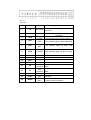
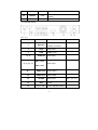
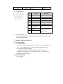
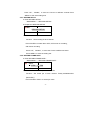
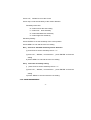
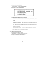
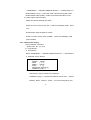
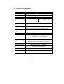
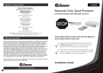
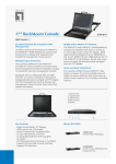
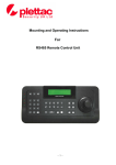
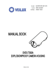
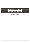
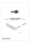
4CH STANDALONE DVR SERIES
Operation Manual
Ver75 1.1
INDEX
1、
、PRODUCT OVERVIEW .......................... 2
2、
、QUICK INSTALLATION INSTRUCTION 3
3、
、HARDWARE OVERVIEW ...................... 3
3.0 THE FRONT PANEL ............................................................................ 3
3.1 THE REAR PANEL .............................................................................. 5
3.2 REMOTE CONTROLLER .................................................................... 6
4、
、SYSTEM SETTING INSTRUCTION ....... 6
4.1 QUICK INSTALLATION.......................................................................... 6
4.2 DIRECT FAST SETTING : ..................................................................... 6
4.3 MENU SETUP ..................................................................................... 7
4.3.1 RECORD SETUP .................................................................... 8
4.3.2 RECORD FRAME RATE.......................................................... 8
4.3.3 VIDEO QUALITY ..................................................................... 9
4.3.4 RECORD SCHEDULE ............................................................. 9
4.3.5 SENSOR SETUP ................................................................... 10
4.3.6 HARD MANAGEMENT ........................................................... 11
4.3.7 MISCELLANEOUS SETUP ................................................... 12
4.3.8 NETWORK SETUP ................................................................ 15
4.3.10 LOAD DEFAULT .................................................................. 18
4.3.11 SEARCH VIDEO .................................................................. 18
5、
、TECHNICAL SPECIFICATIONS .......... 19
-1-
*Before installing and using the unit please read this manual carefully,
Be sure to keep it handy for later reference.
1、
、Product Overview
Thank you for purchasing our 4ch stand-alone DVR. Adopting the most
advanced DSP tech, they supply an entirely solution of video/audio storage and
monitoring. With the network image transmission and PTZ control, they offer a
cost-effective imaging solution with minimal installation and maintenance costs
· Compression format :MPEG-4 for local storage and network transmission
· Resolution:Max. 60(50) Field/sec, 720 x 240(288)
· HDD:1 SATA HDD ,Max 1 TB
( No support
IDE
HDD )
· Support network live view and playback
· Video input:4ch BNC;
· Video output :BNC, network and VGA (option)
· Audio input:2CH;Audio output:1CH
· Support Keyboard and remote control
· Live viewing:Quad or single full screen display
· Recording Mode: manual / Event / Alarm / Motion Detection Schedule
· Playback by schedule and event
· Jumper on board for NTSC/PAL selection
· Embedded operation system enables stable quality and provides a reliable
-2-
platform
2、
、Quick Installation Instruction
2.1 Checking the hardware Inventory
Check the accessories supplied with your DVR as the list below :
Item
Quantity
Digital video recorder
1
DC 12V power adaptor
1
Remote controller
1
CD and user manual
1
Power cable
1
2.2 Basic installation instruction:
:
a. Put the DVR on a dry, steady plat
b. Video input /output at the rear Panel, connect the input of cameras ,and
the output of Monitors or VGA
c. Audio input/output at the rear panel, connect the input of audio signal ,and
the output of audio record equipment
d. Attach the power supplier to the unit and connect it to your local power
supply
3、
、Hardware Overview
Input/Output port:Rear panel(power input,audio/video input and output,
VGA output,USB/Ethernet port)、Front Panel(keyboard)、Remote controller、
3.0 The Front Panel
-3-
Pic. 3_1
Table 3-1
No.
Button
Full name
Function
1
IR
IR receiver
2
REC
record
3
ALM
ALARM
4
HDD
HDD
The indicator lights up when Hard Disk
5
NET
NET
The indicator lights up when LAN
6
POW
POWER
The indicator lights up when turning
7-10
CH1-CH4
Channel
1ch full screen display
11
QUAD
Quad
Quad display
stop
Stop recording
Fast
1.recording fast revert when playing
Flash when receiving signal from remote
controller
The Indicator lights up when
recording
The indicator lights up when alarm in
12
REC
13
STOP
14
FR
15
FF
16
PAUSE
pause
17
PLAY
play
Playback
18
MENU
Main
1.Enter main menu
revert/left
Fast
play/right
Menu
back.
1.recording fast forward when playing
back
2.
Cursor
right
moving in system setting
Pause
play
back
2.Return and save settings
-4-
19
DOWN
down
20
ENTER
enter
21
UP
Up
Move the cursor Down on menu
Enter the submenu and save new
setting
Move the cursor up on menu
3.1 The Rear Panel
Pic. 3_2
No.
Button
1
Ethernet
function
reference
RJ-45 port for
network connection
2
VGA
VGA output
3
USB
USB 2.0 port
4、
、6
AUDIO IN
Audio input
CH1、
、CH2
5、
、7、
、9、
、11
Video input
CH3、
、CH4
8、
、
AUDIO OUT Audio output
10
VIDEO OUT
Video output
12
ALARM
Alarm Input
13
FAN
14
Power SW
Air fan
Power ON/OFF switch
-5-
refer:pic. 3_3
15
Power in
Power
DC12V
Pic. 3_3 Alarm input
No.
button
reference
1
Alarm input1
N.O. / N.C..
2
Alarm input2
N.O. / N.C..
3
Alarm input3
N.O. / N.C..
4
Alarm input4
N.O. / N.C..
5
Alarm input COM
6
Relay NO output
7
Relay NO output
common port
3.2
8
485A
9
485B
PELCO-P/PELCO-D
bitrate:9600
Remote Controller
The functions of buttons on remote controller are the same as the buttons
on the keyboard of DVR
4、
、System Setting Instruction
4.1 Quick installation
a.
HDD Installation
Cut off the power supply for DVR → remove the cover by using screw
tool
b.
→fix a HDD in the unit →properly connect the HDD cables
PAL/NTSC Standard Selection
Follow the instruction as below to select the standard you need:
find SW1 on main board → jump to NTSC or PAL → close the cover
C. connect the power supply
4.2 Direct Fast Setting :
a. Time Setting
-6-
"MENU" →"MISCELLANEOUS SETUP" →"SET TIME"
b. Password Setting
"MENU" →"MISCELLANEOUS SETUP" →" CHANGE PASSWORD "
c. HDD format
"MENU" →"HARD MANAGEMENT"→" HARD MANAGEMENT "
Please make sure of shutting down the power before install or change the
HDD
keyboard Lock: Exit menu mode, and then press FR button 5 times.
4.3 Menu setup
Press Menu to enter the main menu setup, as following :
CAMERA SETUP
RECORD SETUP
RECORD FRAMLRATE
VIDEO QUALITY
RECORD SCHEDULE
SENSOR SETUP
HARD MANAGEMENT
MISCELLANEOUS
SETUP
NETWORK SETUP
VIDEO BACKUP
LOAD DEFAULT
4.3.0 CAMERA SETUP
a. Enter CAMERA SETUP
"MAIN MENU" →"CAMERA SETUP"
b. Snapshot of CAMERA SETUP
1》
》ON
3 ON
2 ON
CAMERA SETUP
4 ON
c. CAMERA SETUP operation instruction
Function:Set live viewing of each channel on the monitor Press “ENTER”
to select ON or OFF;OFF means no display,ON means display
-7-
Press “UP”、“DOWN”、to move the Cursor to different channel Press
“MENU” to exit save setting and.
4.3.1 RECORD SETUP
a. Enter RECORD SETUP
" MAIN MENU " →"RECORD SETUP "
b. Snapshot of RECORD SETUP
2 ON
1》
》ON
RECORD SETUP
3 ON
4 ON
c. RECORD SETUP operation instruction
Function:Set recording of each channel
Press “ENTER” to select ON or OFF, OFF mean no recording,
ON means recording
Press “UP”、“DOWN”、to move the Cursor to different channel
Press “MENU” to save the setting exit
4.3.2 RECORD FRAME RATE
a. Enter RECORD FRAME RATE !
" MAIN MENU " →"RECORD FRAME/RATE"
1》
》
3
2 FPS
2
1 FPS
TOTAL: 5 FPS
1 FPS
4
1 FPS
b. RECORD FRAMERATE operation instruction
Function : Set record fps of each channel .Totally 50/60frame/sec
(PAL/NTSC)
Press “ENTER””STOP” to set the fps value
-8-
Press “UP”、“DOWN”、to move the Cursor to different channel
Press “MENU” to exit and saver the setting and.
4.3.3 VIDEO QUALITY
a. Enter VIDEO QUALITY
" MAIN MENU " →" VIDEO QUALITY "
b. VIDEO QUALITY operation instruction
Function:set the quality of the record; With high level ,you can get
better quality picture, Meantime, it takes more capacity of the HDD
Press “ENTER” to set the record level Record
Level: HIGHEST/HIGHER/HIGH/BETTER/NORMAL/LOW/LOWER/
LOWEREST
Press “MENU” to exit and save the new setting
4.3.4 RECORD SCHEDULE
a. Enter RECORD SCHEDULE
" MAIN MENU " → "RECORD SCHEDULE"
b. Snapshot of RECORD SCHEDULE
AM
PM
0 . . 3 . . 6 . . 9 . . 12. . 15. 18. . 21. .
■■■■■■■■■■■■■■■■■■■■■■■■
▲
■
NO-RECORD
■
RECORD
S
SENSOR-RECORD
c. RECORD SCHEDULE operation instruction
Function:set therecord mode, NO-RECORD/RECORD/NSOR-RECORD
Stands for 24 hours in a day
Press “ENTER” to set mode
Press “UP”、“DOWN” to move the cursor
Press “MENU” to exit and save the new setting
-9-
4.3.5 SENSOR SETUP
a. Enter SENSOR SETUP
" MAIN MENU " →"SENSOR SETUP"
b. Snapshot of SENSOR SETUP
》SENSORED RECORD TIME
05
ALARM ON TIME 05
H/W SENSOR SETUP
c. SENSOR SETUP operation instruction:
Function:set the parameter of sensor alarm
SENSORED RECORD TIME:set the record length (seconds),
ALARM ON TIME:set the time length of alarm output
H/W SENSOR SETUP:set the sensor setting and the statement ;NOT
INSTALLED /NORMAL-OPEN/ NORMAL-CLOSE
Press “MENU” to exit and save the new setting
MOTION DETECTOR SETUP:Set the area of motion detection
MOTION DETECTOR SETUP
》CH-1 OFF
AREA
CH-2 OFF AREA
CH-3 OFF AREA
CH-4 OFF AREA
Press “FR/LF”、“FF/RT”、“UP”、“DOWN” to move the Cursor
Select “AREA”,press “ENTER” to set the motion detection area,
MD AREA CH1 SENS *:0
- 10 -
:1
:2
:3
Press “UP”、“DOWN” to move the Cursor
Press “stop” to set the sensitivity of the motion detection
Sensitivity instruction:
" 0 "means cancel the area setting
" 1 "means low
level sensitivity
" 2 "means standard level sensitivity
" 3 "means high level sensitivity
Sensitivity Setting:
Press “ENTER” to set the sensitivity of the cursor position
Press “MENU” to exit and save the new setting
Ex.1、
、set area to standard sensitivity motion detection
i) press STOP to set the sensitivity level to " 2 "
ii) press “UP”、“DOWN”、to set the area ,press “ENTER” to finish the
setting
iii) Press “MENU” to exit and save the new setting
Ex.2、
、cancel the sensitivity setting
i)
press STOP to set the sensitivity level to " 0 "
ii) press “UP”、“DOWN”、to set the area ,press “ENTER” to finish the
setting
iii) Press “MENU” to exit and save the new setting
4.3.6 HARD MANAGEMENT
- 11 -
a. Enter HARD MANAGEMENT
" MAIN MENU " →"HARD MANAGEMENT"
b. Snapshot of HARD MANAGEMENT
》 OVERWRITE ENABLED [YES]
HDS728080PLA380
MASTER HDD SIZE 160000MB
MASTER HDD USED 80000MB
MASTER HDD FORMAT
SLAVE HDD SIZE N/A
SLAVE HDD USED N/A
SLAVE HDD FORMAT
50%
c. HARD MANAGEMENT operation instruction
Function:set the record overwrite mode of HDD、HDD status、HDD
format
OVERWRITE ENABLED:YES means the new record will cover the old
one ,old record will be lost;NO means the record will be stopped when
the HDD is full written
MASTER HDD FORMAT:Format the HDD All information will be lost
Press “MENU” to exit and save the new setting
4.3.7 MISCELLANEOUS SETUP
a. Enter MISCELLANEOUS SETUP
" MAIN MENU " →"MISCELLANEOUS SETUP "
b. Snapshot of MISCELLANEOUS SETUP
- 12 -
》CHANGE PASSWORD
SET TIME
HIDDEN CHANNEL [OFF]
AUDIO PORT1: CH=
[1]
AUDIO PORT2: CH=
[2]
AUDIO PORT1: REC
[YES]
AUDIO PORT2: REC
[YES]
PTZ SETUP
c. MISCELLANEOUS SETUP operation instruction
CHANGE PASSWORD:change the user password
SET TIME:set system time
HIDDEN CHANNEL:display live viewing or not
AUDIO PORT1: CH=
[1] select the video channel working with audio
AUDIO PORT2: CH=
[2]
AUDIO PORT1: REC
[YES] audio record same with video record
AUDIO PORT2: REC
[YES]
PTZ CONTROL:
Snapshot of PTZ control menu:
4.3.7.0 CHANGE PASSWORD
“MAIN MENU " →"MISCELLANEOUS SETUP " →"CHANGE PASSWORD "
default password: 111111
4.3.7.1 SET TIME
" MAIN MENU " →"MISCELLANEOUS SETUP " →"SET TIME "
4.3.7.2 AUDIO Setting
i). Audio channel and audio record setting
- 13 -
:" MAIN MENU " →"MISCELLANEOUS SETUP "→" AUDIO PORT1/2 "
"AUDIO PORT1:CH=[ 1 ] ":elect the video channel working with audio
"AUDIO PORT1:REC=[YES] ": audio record same with video record
ii). Audio output channel setting
Select the channel working with audio:
Under non-menu mode, press “UP”;under record-display mode,press
“UP”
Set the audio output enabled or closed:
Under non-menu mode, press “DOWN”;under record-display mode,
press “DOWN”
4.3.7.3 PTZ control setting
i).PTZ hardware connection
please refer“ pic. 3_3” (P4)
ii). " PTZ SETUP"
a. PTZ SETUP
Route:" MAIN MENU " →"MISCELLANEOUS SETUP "→" PTZ SETUP"
b. Snapshot of PTZ SETUP:
PTZ SETUP
SPEED
[9600]
DATA
[ 8]
PARITY [None]
STOP
[ 1]
PROTOCOL [PELCO-P]
CAMERA-[ 1] ID-[ 1 ]
c. PTZ SETUP operation instruction
PROTOCOL: PELCO-P/PELCO-D optioned
CAMERA-[ 1] ID-[ 1 ]:set the PTZ address code of each
channel
SPEED、DATA、PARITY、STOP can not be changed by user
- 14 -
iii). "PTZ CONTROL" setting
a. PTZ CONTROL
Route : " MAIN MENU " →"MISCELLANEOUS SETUP "
b. Snapshot of
PTZ CONTROL
PTZ CONTROL
》UP
DOWN
LEFT
RIGHT
ZOOMZOOM+
FOCUSFOCUS+
IRISIRIS+
c. PTZ CONTROL operation instruction
1). Press “UP”、“DOWN” to move the Cursor
2). Press “ENTER” to confirm the setting
3). Press “MENU” to exit and save the new setting
4.3.8 NETWORK SETUP
a. Enter NETWORK SETUP
" MAIN MENU " →"NETWORK SETUP"
b. Snapshot of NETWORK SETUP
》MAC ADDRESS..<FF:FF:FF:FF:FF:FF>
IP ALLOCATION..[DHCP]
IP ADDRESS……<0.0.0.0>
SUBNET MASK..<0.0.0.0>
GATEWAY……...<0.0.0.0>
DNS1 ADDRESS..[0.0.0.0]
DNS2 ADDRESS..[0.0.0.0]
HTTP PORT......
USER SETUP……
DDNS SETUP….
c. NETWORK SETUP operation instruction
MAC ADDRESS:Can not be changed by user
- 15 -
IP ALLOCATION:Input the IP address of the unit.
IP ADDRESS:set subnet mask address of the unit.
SUBNET MASK:set gateway of the unit.
GATEWAY:
DNS1 ADDRESS:
DNS2 ADDRESS:
HTTP PORT:
USER SETUP:set up of user name and password
DDNS SETUP:
d. Net live view operation instruction:Install the Active x:
- 16 -
4.3.9 VIDEO BACKUP
a. Enter VIDEO BACKUP
"MENU" →"VIDEO BACKUP "
b. Snapshot of
VIDEO BACKUP
》START:2000/00/00
00:00:00
END :2000/00/00 00:00:00
SIZE
:[]MB
FILENAME:[VID000.MCG]
BACKUP TO USB DEVICE
c. VIDEO BACKUP operation instruction
Function:backup the record by USB 2.0
START: start time, END, end time;
FILENAME: name of backup documents
Press “MENU” to exit and save the new setting
d. display of the backup record
Run “Dvr4ChBkViewerV1_0.exe,”in the CD,select and display the record
- 17 -
you have backup in the computer
4.3.10 LOAD DEFAULT
a. Enter LOAD DEFAULT
"MENU" →"LOAD DEFAULT "
b. Snapshot of LOAD DEFAULT
PUSH DVR SYSTEM PASSWORD
TO LOAD DEFAULT CONFIGURATION
EXCEPT OF
NETWORK
MENU
AND
SYSTEM
PASSWORD
〈
c.
LOAD DEFAULT operation instruction
Function:After input the correct password,All setting will be back to
factory setting except the Network menu and system password
4.3.11 SEARCH VIDEO
a. SEARCH VIDEO
Route : under non-menu
mode,press "PLAY" →"MENU"
b. Snapshot of SEARCH VIDEO
SEARCH VIDEO
DISK: MASTER
07/10/24 10:50:45- 07/10/24 10:53:45
TYPE: EVENT
TIME
PLAY: EVENTS
》00000 T 2007/10/24 10:50:45
c. SEARCH VIDEO operation instruction
Press “MENU” to exit
Press “UP”、“DOWN” to move the cursor to select the submenu,
Press “ENTER” to get into submenu
- 18 -
5、
、Technical Specifications
Model
No.
HDD
Standard Model
VGA Model
1 sata HDD ,Max 500 G
( No support
Video input
BNC X 4
Alarm input
4ch (N.O. or N.C.)
Video output
BNC
IDE
HDD )
BNC ;VGA
Audio input/output
2ch /1ch
Compression
MPEG-4
format
Resolution
NTSC: Max.60Frames/sec, PAL: Max. 50 frames/sec.
NTSC: 720 x 240 (HD1)
Alarm output
PAL: 720 x288 (HD1)
Relay NC or NO
Video standard
NTSC/PAL
Record event
Max . 1600 events
USB Backup
USB 2.0
View Mode
P/T/Z
Record mode
Net remote control
Operation Method
1ch full screen 、4ch quad display
PELCO-P/PELCO-D protocol
Manual、Alarm、Motion detection、schedule
Remote net live view / 5 user Max.
keyboard、remote controller
Work Temperature
-5℃--45℃
Power input
Measure
(RH 85%)
DC12V /3A
360mm(W)x220mm(D)x44mm(H)
- 19 -
Version:Ver75
1.1
Version:
Date:Jun.2008
Date:
Design and specifications are subject to change without notice.
-1-