1
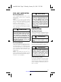
www.SeaDooManuals.net
smo9803a.fm5 Page -1 Thursday, January 29, 1998 8:38 AM
SEA-DOO GTX RFI (5666/5843)
OPERATOR’S GUIDE SUPPLEMENT
This Operator’s Guide Supplement contains information specifically applicable to
the GTX RFI (5666/5843) model.
This supplement must be used in conjunction with the 1998 Sea-Doo Operator’s
Guide (P/N 219 000 076), which contains all the general information. When a
specific model is discussed, refer to the information regarding the GTX Limited,
except for the following subjects covered in this supplement.
◆ SAFETY WARNING
Disregarding any of the safety precautions and instructions contained in
this Operator’s Guide Supplement, the Operator’s Guide, the Safety
Handbook and on Product Warning Labels could cause injury, including
the possibility of death.
This Operator’s Guide Supplement, the Operator’s Guide, the Safety
Handbook and Videocassette should remain with the watercraft at the
time of resale.
Litho’d in Canada (SMO-9803 FY)
®*Trademarks of Bombardier Inc.
All rights reserved © Bombardier Inc. 1998
www.SeaDooManuals.net
smo9803a.fm5 Page 0 Thursday, January 29, 1998 8:38 AM
TABLE OF CONTENTS
LOCATION OF THE IMPORTANT LABELS....................................
1
WATERCRAFT IDENTIFICATION ..................................................
COMPONENT FUNCTIONS .........................................................
3
3
FUEL AND LUBRICATION ...........................................................
5
OPERATING INSTRUCTIONS ......................................................
POST-OPERATION CARE.............................................................
5
6
SPECIAL PROCEDURES..............................................................
7
MAINTENANCE ..........................................................................
9
STORAGE ................................................................................... 11
10-HOUR INSPECTION CHECK LIST ........................................... 14
PERIODIC INSPECTION CHART .................................................. 15
PRE-SEASON PREPARATION CHART.......................................... 16
TROUBLESHOOTING................................................................... 17
SPECIFICATIONS ........................................................................ 20
www.SeaDooManuals.net
smo9803a.fm5 Page 1 Thursday, January 29, 1998 8:38 AM
LOCATION OF THE IMPORTANT LABELS
Please read the following labels carefully before operating this watercraft.
1
10
6
5
2
3
7
F07L0TL
1
www.SeaDooManuals.net
smo9803a.fm5 Page 2 Monday, January 26, 1998 3:55 PM
1
WARNING
Read all warning label, Operator Guide & safety documents before operating.
Severe injury or death can result from ignoring such information or improper use of the watercraft.
Check throttle & steering operation before starting engine.
Directional control is lost when throttle is released or engine shut off.
Do not splash others or jump waves or wakes with this watercraft.
Properly attach safety tether to your PFD.
Keep a safe distance from other water users. Observe boating regulations.
This watercraft is not design for night-time operation.
F00A0RL
2
7
CAUTION
TO AVOID POSSIBLE ENGINE FLOODING WHEN ROLLED OVER:
• CAUTION
MAKE SURE ENGINE IS OFF
USE BOMBARDIER-ROTAX INJECTION OIL OR
HIGHER QUALITY LOW ASH API TC INJECTION
OIL FOR 2 CYCLES ENGINES.
GRAB INLET GRATE AND STEP
ON BUMPER RAIL
ROLL BOAT COUNTERCLOCKWISE
NEVER USE NMMA TC-W, TC-WII or TC-W3 outboard motor oils.
F00L06Z
F06L0DY
"THIS BOAT IS NOT REQUIRED TO COMPLY WITH THE
FOLLOWING U.S. COAST GUARD SAFETY STANDARDS
IN EFFECT ON THE DATE OF CERTIFICATION:
3
Safe Loading
Flotation
Powered Ventilation
Fuel System
Display of Capacity
Information
AS AUTHORIZED BY U.S. COAST GUARD GRANT OF
EXEMPTION (CGB 88-001)."
Bombardier Corp.
7575 Bombardier Court, Wausau, WI 54401
Made in Canada/Fabriqué au Canada
Bombardier Inc. Rd./Enr.,1988
F02L2DZ
10
WARNING
ENGINE MUST BE OFF WHEN USING BOARDING STEP.
KEEP AWAY FROM JET OR INTAKE GRATE. STAY ON
CENTER OF THE STEP. ONLY ONE PERSON AT THE
TIME ON THE STEP. NEVER USE THE STEP FOR
PULLING, TOWING, DIVING OR JUMPING, BOARDING
A PWC THAT IS OUT OF WATER OR ANY OTHER
PURPOSE FOR WHICH IT WAS NOT DESIGNED.
F07L11Y
5
WARNING
WHILE FUELING, STOP ENGINE. FUEL TANK MAY BE
PRESSURIZED, SLOWLY TURN CAP WHEN OPENING.
KEEP WATERCRAFT LEVEL. DO NOT OVERFILL. CHECK
OIL LEVEL. PERIODICALLY, VERIFY FUEL SYSTEM.
F01L6VY
6
• WARNING
DO NOT BOOST BATTERY
WHILE INSTALLED.
F00L05Y
2
www.SeaDooManuals.net
smo9803a.fm5 Page 3 Monday, January 26, 1998 3:55 PM
WATERCRAFT
IDENTIFICATION
To lock the storage compartment cover, insert key and rotate it 1/2 turn.
Engine Identification Number
The Engine Identification Number
(E.I.N.) is located on the upper crankcase on PTO side.
1
F07L0VY
1. Insert key and rotate it 1/2 turn to lock cover
To unlock the storage compartment
cover, turn key in the opposite direction.
F01D87Y
1
1. Engine Identification Number
COMPONENT FUNCTIONS
Added Features
The following features have been added for this specific model.
Adjustable Handlebar
The handlebar height can be adjusted
to suit rider preferences.
To perform this adjustment, turn the
knob underneath the handlebar.
Storage Compartment Cover
Safety Lock
A convenient lock is provided to protect personal articles when the watercraft is unattended.
1
1
F07L0WY
1. Adjustment knob
Cargo Cleats
These cleats are provided for securing
baggage.
-
F07L0UY
1. Safety lock
CAUTION
Do not use the cleats as a tiedown point for transportation or
mooring.
3
www.SeaDooManuals.net
smo9803a.fm5 Page 4 Monday, January 26, 1998 3:55 PM
Bow Bag
A convenient watertight bow bag is
supplied with this watercraft. The bow
bag is tailor-made for the front storage
compartment.
Modified or Deleted Features
The following features have been either modified or deleted for this specific model.
1
F07L0XY
1. Cargo cleats (each side)
Stern Eyelet
This eyelet allows a rope with a hook,
a closed end or an open end to be attached.
Throttle Lever
When the engine is stopped, no fuel is
injected when depressing the throttle
lever. The carburetors are replaced by
a throttle body. Any reference to the
carburetors in the Operator’s Guide
should be disregarded.
Choke Lever
There is no choke lever. The enrichment of the air/fuel mixture is controlled by the electronic control unit
(ECU). Any reference to the choke cable in the Operator’s Guide should be
disregarded.
1
F07L0YY
1. Stern eyelet
Boarding Step
A convenient step to help reboarding
the watercraft.
◆
WARNING
Engine must be OFF when using
boarding step. Keep away from
jet or intake grate. Stay on center
of the step. Only one person at
the time on the step. Never use
the step for pulling, towing, diving or jumping, boarding a PWC
that is out of water or any other
purpose for which it was not designed.
Fuel Valve
With the Rotax Fuel Injection, there is
no need for a fuel valve.
There is no reserve. When the fuel is
low in the tank (1/8), the Info Center
displays a “LOW FUEL” warning message and the LED will blink. Every 55
seconds, the monitoring beeper will
also sound 5 seconds to warn the operator.
◆
WARNING
Always refill the fuel tank at the
first opportunity.
Any reference to the fuel valve in the
Operator’s Guide should be disregarded.
4
www.SeaDooManuals.net
smo9803a.fm5 Page 5 Monday, January 26, 1998 3:55 PM
FUEL AND LUBRICATION
Recommended Fuel
Use unleaded gasoline with a minimum of 87 octane (RON + MON/2)
specification.
NOTE: Look on service station pump
sticker for octane specification. Do not
mix oil with fuel except at engine
break-in. Always check injection oil
tank level when refueling.
The use of good quality fuel is necessary. A well known fuel brand is highly
recommended.
-
CAUTION
Never experiment with other fuels or fuel ratios. Never use fuel
containing more than 10% alcohol (ethanol or methanol). The
use of non-recommended fuel can
result in watercraft performance
deterioration and damage to critical parts in the fuel system and
engine components.
Recommended Oil
Use BOMBARDIER ROTAX INJECTION OIL which is available from authorized dealers. It is a blend of specially selected base oils and additives
which provides proper lubrication, engine cleanliness and minimum spark
plug fouling.
NOTE: High quality low ash API TC injection oil for 2-cycle engines can be
used if BOMBARDIER ROTAX INJECTION OIL is not available.
-
CAUTION
Never use 4-cycle petroleum or
synthetic motor oil and never mix
these with outboard motor oil.
Do not use NMMA TC-W, TC-W2
or TC-W3 outboard motor oils or
other ashless type 2-cycle oil.
Avoid mixing different brands of
API TC oil as resulting chemical
reaction may cause severe engine damage.
OPERATING
INSTRUCTIONS
Starting the Engine
Before unloading the watercraft from
the trailer, it can be started for about
10 seconds to verify proper operation.
◆
WARNING
Do not touch electrical parts or jet
pump area when engine is running.
Attach the safety lanyard to the operator’s PFD and snap the cap to the
switch before starting the engine.
◆
WARNING
Only start the watercraft once all
controls have been checked and
operate properly. Operator and
passenger (if applicable) should
be sitting on the watercraft seat
prior to starting the engine.
Cold and Warm Engine
Firmly grip handlebar with both hands
and place both feet on the floorboard.
To start engine, depress and hold the
button. Release immediately after engine is started.
5
www.SeaDooManuals.net
smo9803a.fm5 Page 6 Friday, February 20, 1998 3:40 PM
NOTE: Do not depress the throttle lever to start either a cold or warm engine.
Slowly accelerate to reach deeper
water. Do not apply full throttle until
the engine is at normal operating temperature.
◆
To flush engine, connect a garden
hose to the water outlet located at the
rear of watercraft near the jet pump.
NOTE: A quick connect adapter is
supplied with the watercraft and can
be used to ease hose installation.
WARNING
In shallow water, shells, sand,
pebbles or other objects could be
drawn up by the jet pump and
damage impeller, components or
clog the cooling system. Also, debris could be thrown rearward
into bystanders.
POST-OPERATION CARE
Cooling System Flushing and
Engine Internal Lubrication
Flushing the cooling system with
fresh water is essential to neutralize
corroding effects of salt or other chemical products present in water. It will
help to clean up sand, salt, shells or
other particles in water jackets (engine, exhaust manifold, tuned pipe)
and/or hoses.
Engine lubrication and flushing should
be performed when the watercraft is
not expected to be used further the
same day or when the watercraft is
stored for any extended time.
Proceed as follows:
◆
WARNING
Perform this operation in a well
ventilated area.
Clean jet pump by spraying water in its
inlet and outlet and then BOMBARDIER LUBE lubricant.
6
3
F07E01Y
2
1
TYPICAL
1. Water outlet
2. Quick connect adapter (supplied)
3. Garden hose
Start the engine then immediately
open the water tap.
◆
WARNING
Do not touch any electrical parts
or jet pump area when engine is
running.
-
CAUTION
Never flush a hot engine. Always
start the engine before opening
the water tap. Open water tap immediately after engine is started
to prevent overheating.
Run the engine about 3 minutes at a
fast idle around 3500 RPM.
www.SeaDooManuals.net
smo9803a.fm5 Page 7 Friday, February 20, 1998 3:41 PM
Spray BOMBARDIER LUBE lubricant
into air intake silencer keeping engine
at fast idle.
2
1
3
F07H0AY
1
1. Grounding device
F01F25Y
1. Air intake silencer
2. Pull plug
3. Spray BOMBARDIER LUBE here
NOTE: Lubrication of engine should
be done for at least 1 minute. Close
the water tap then stop the engine.
-
CAUTION
Always close the water tap before stopping the engine.
Disconnect the garden hose.
Wipe up any residual water from the
engine.
Remove spark plug cables and connect them on the grounding device.
◆
WARNING
Always use spark plug cable
grounding device when removing spark plugs.
Remove both spark plugs and spray
BOMBARDIER LUBE lubricant into
each cylinder.
NOTE: For the storage period, use
Bombardier storage oil (P/N 413 711
600).
Fully apply the throttle lever then depress the start/stop button to crank
the engine a few turns to distribute
the oil onto cylinder wall.
NOTE: No fuel is injected in the engine when the throttle lever is fully applied then the starter activated.
Apply anti-seize lubricant on spark
plug threads then reinstall them.
Reinstall plug on air intake silencer
cover.
NOTE: Engine fogging should be
done whenever the watercraft is to be
stored for a few days or a long period.
SPECIAL PROCEDURES
Submerged Watercraft
If the watercraft is submerged and engine is water-flooded, it is strongly recommended that the watercraft be serviced by an authorized dealer immediately.
In the event the engine cannot be serviced within a few hours, remove
spark plug cables and connect them
on the grounding device.
www.SeaDooManuals.net
7
smo9803a.fm5 Page 8 Monday, January 26, 1998 3:55 PM
◆
WARNING
Never crank engine with spark
plugs removed unless spark plug
cables are connected to the
grounding device.
Remove spark plugs and dry them
with a clean and dry cloth.
Cover spark plug holes with a rag.
Fully apply the throttle lever then depress the start/stop button to crank
engine for approximately 10 seconds.
This will allow water to escape from
spark plug openings.
Spray BOMBARDIER LUBE lubricant
into spark plug holes.
Crank engine again with the throttle
fully applied.
Reinstall spark plugs.
Towing the Watercraft in Water
Special precautions should be taken
when towing a Sea-Doo watercraft in
water.
Maximum recommended towing speed
is 24 km/h (15 MPH).
When towing your watercraft in water,
pinch the water supply hose from the
impeller housing to the engine with a
large hose pincher (P/N 529 030 400)
shown in the following illustration.
This will prevent the cooling system
from filling which may lead to water
being injected into and filling the exhaust system. Without the engine running there isn’t any exhaust pressure
to carry the water out of the exhaust
outlet.
-
CAUTION
Failure to do this may result in
damage to the engine. If you
must tow a stranded watercraft in
water and do not have a hose
pincher be sure to stay well below the maximum towing speed
of 24 km/h (15 MPH).
Snugly install the hose pincher on the
hose as shown.
1
F07E04Y
1. Hose pincher
-
CAUTION
When finished towing the watercraft, hose pincher must be removed before operating it.
F01B23Y
8
www.SeaDooManuals.net
smo9803a.fm5 Page 9 Friday, February 20, 1998 3:41 PM
Flooded Engine
If the engine does not start and it is
suspected to be flooded, proceed as
follows:
Remove spark plug cables and connect them on the grounding device.
◆
2
WARNING
Always use spark plug cable
grounding device when removing spark plugs.
Remove spark plugs and dry them using a rag.
Cover spark plug holes with a rag.
Install the safety lanyard cap on the
switch.
Depress and hold the throttle lever at
full throttle position.
Depress the start/stop button to crank
the engine approximately 10 seconds.
Proceeding in this order, no fuel is injected and the accumulated fuel in the
engine will be expelled.
Reinstall spark plugs and connect cables.
Start engine normally without applying
the throttle.
1
F01I0AY
1. Flywheel guard
2. Wing nuts
Using a grease gun, carefully lubricate
PTO flywheel at grease fitting until
boot is just beginning to expand.
-
CAUTION
Immediately stop lubricating as
soon as boot begins to expand.
MAINTENANCE
Lubrication
Use SEA-DOO synthetic grease and
lubricate the PTO flywheel every 10
hours. Proceed as follows:
Remove seats to expose engine compartment.
Remove the wing nuts, washers and
pull out PTO flywheel guard.
◆
F01I0BY
1
1. Grease PTO flywheel
Secure PTO flywheel guard.
WARNING
Always remove safety lanyard
cap from its receptacle to prevent
accidental engine starting before
r e mo vi n g th e PT O f l yw he e l
guard.
www.SeaDooManuals.net
9
smo9803a.fm5 Page 10 Monday, January 26, 1998 3:55 PM
Fuses
The electrical system is protected
with 5 fuses.
Three fuses are located on the MultiPurpose Electronic Module (MPEM)
and the other two fuses are in the rear
electrical box.
Two fuses protect the charging system. If the battery is regularly discharged, check the 15 A fuse on the
MPEM and the 20 A fuse in the rear
electrical box.
A 5 A fuse protects the power supply
of the MPEM. If the starter does not
operate, check the 5 A fuse.
The second 20 A fuse in the rear electrical box protects the power supply of
the Electronic Control Unit (ECU).
The 7.5 A fuse on the MPEM protects
the fuel pump. If the engine does not
start, check this fuse.
To access fuses on the Multi-Purpose
Electronic Module, open storage compartment cover and remove basket.
Locate MPEM on the left side of watercraft.
Unclip the fuse cover from the MPEM.
1
F06H1TY
NOTE: There is 2 spare fuses on the
MPEM.
To access the 20 A fuses in the rear
electrical box, remove seats.
Remove basket.
Unclip and remove cover of the rear
electrical box.
1
F07H08Y
1
1. Rear electrical box
1
F06H1SY
2
TYPICAL
1. MPEM
2. Fuse cover
Use the tabs of the fuse cover to remove and reinstall fuses.
2
1. Fuse cover
2. Fuse tabs
F07H09Y
REAR ELECTRICAL BOX OPENED
1. Fuse holders
10
www.SeaDooManuals.net
smo9803a.fm5 Page 11 Monday, January 26, 1998 3:55 PM
Unclip and pull out fuse holders to
check fuse condition.
If a fuse is defective, replace it by one
of the same rating.
-
CAUTION
Do not use a higher rated fuse as
this can cause severe damage.
Refer to SPECIFICATIONS section
for recommended fuse rating. If a
fuse is regularly burnt, refer to an
authorized dealer.
◆
WARNING
If any water is found in the rear
electrical box, immediately refer
to an authorized dealer before
operating the watercraft.
1
F07E05Y
1. Disconnect this hose
Water should flow out of the fitting
(magneto cooling circuit) and hose
(crankcase heat exchanger).
NOTE: Ensure to properly close cover
of the rear electrical box, making sure
seal is well positioned.
STORAGE
It is recommended that the watercraft
be serviced by an authorized dealer for
storage but the following operations
can be performed by you with a minimum of tools.
-
F07E06Y
Engine Draining
Disconnect the water supply hose
used to cool the magneto. It features
a quick connect fitting. Press both
tabs and pull fitting in order to disconnect hose.
This hose is located at the bottom of
the magneto cover beside the engine
support.
1
1. Make sure water flows out of fitting and
hose
-
CAUTION
Do not run the engine during the
storage period.
1
CAUTION
Water in engine must be free to
flow out. Should water freeze in
engine, severe damage will occur.
Fuel System
SEA-DOO fuel stabilizer (or equivalent), can be added in fuel tank to prevent fuel deterioration. Follow manufacturer’s instructions for proper use.
NOTE: Fuel stabilizer should be added
prior engine lubrication.
11
www.SeaDooManuals.net
smo9803a.fm5 Page 12 Monday, January 26, 1998 3:55 PM
Cooling System Flushing and
Engine Internal Lubrication
Refer to procedure in POST-OPERATION
CARE.
Propulsion System
Lubricant in jet pump reservoir should
be drained and reservoir cleaned. Refill with SEA-DOO synthetic polyolester oil (75W90 GL5 type C gear lube).
Refer to an authorized dealer for this
operation.
-
CAUTION
Use only SEA-DOO jet pump oil
or equivalent synthetic gear oil,
otherwise component service life
could be reduced. Do not mix oil
brands or types.
Grease PTO flywheel as explained in
the MAINTENANCE section.
Battery
Contact your authorized dealer or refer
to the appropriate Shop Manual for
proper storage procedure.
Watercraft Cleaning
Clean the bilge with hot water and detergent or with bilge cleaner. Rinse
thoroughly. Lift front end of watercraft
to completely drain bilge. If any repairs
are needed to body or to the hull contact your dealer. For paint touch up to
mechanical parts use Bombardier
spray paint. For small gelcoat repairs,
a Bombardier repair kit is available. Replace damaged labels/decals.
NOTE: Bilge cleaning should be done
prior to anticorrosion treatment.
Wash the body with soap and water
solution (only use mild detergent).
Rinse thoroughly with fresh water. Remove marine organisms from the hull.
Apply a good quality marine wax.
-
CAUTION
Never clean apparent fiberglass
and plastic parts with strong detergent, degreasing agent, paint
thinner, acetone, etc.
If the watercraft is to be stored outside, cover it with an opaque tarpaulin
to prevent sun rays and grime from affecting the plastic components, watercraft finish as well as preventing
dust accumulation.
-
CAUTION
The watercraft must never be left
in water for storage. Never leave
the watercraft stored in direct
sunlight.
Anticorrosion Treatment
Wipe off any residual water in the engine compartment.
Spray BOMBARDIER LUBE lubricant
over metallic components in engine
compartment.
Lubricate the throttle cable with BOMBARDIER LUBE lubricant.
The front seat should be partially left
opened during storage. This will avoid
engine compartment condensation
and possible corrosion.
Additional Recommended
Protection
In cool regions (where freezing point
may be encountered), cooling system
should be filled with an equal part of
water and antifreeze solution.
-
CAUTION
During winter storage in cold climates (where freezing may occur), always add antifreeze and
water solution to cooling system.
Mix in equal parts.
12
www.SeaDooManuals.net
smo9803a.fm5 Page 13 Monday, January 26, 1998 3:55 PM
-
CAUTION
Always use ethylene glycol antifreeze containing corrosion inhibitors specifically recommended
for aluminum engines.
Install a hose pincher to water return
hose of the magneto cooling circuit.
F06E0FY
1
TYPICAL
1. Hose pincher installed on the engine water
supply hose
F07E07Y
1
1. Hose pincher to water return hose
Disconnect the engine water return
hose.
F06E0EY
1
TYPICAL
1. Disconnect the engine water return hose
Install a hose pincher to engine water
supply hose.
Temporarily install a short piece of
hose to engine water return at cylinder head.
Insert a funnel into hose and pour antifreeze mixed with water in engine
until the colored solution appears in
the water return hose of the magneto
cooling circuit.
Remove temporary hose and reconnect engine water return hose.
Remove hose pinchers.
Most of the antifreeze will drain out
from fitting near the exhaust outlet
when removing the hose pinchers.
Use a container to recover it. DISPOSE OF ANTIFREEZE AS PER YOUR
LOCAL LAWS AND REGULATIONS.
NOTE: Although antifreeze will mainly
drain out, the antifreeze has mixed
with the water that was possibly
trapped in the cylinder water jackets,
crankcase heat exchanger and the
magneto cooling circuit, preventing
freezing problems.
At pre-season preparation, drain the
remaining antifreeze from cooling system prior using the watercraft.
13
www.SeaDooManuals.net
smo9803a.fm5 Page 14 Monday, January 26, 1998 3:55 PM
10-HOUR INSPECTION CHECK LIST
✓
DESCRIPTION
Engine ignition timing if required
Spark plug inspection, cleaning and adjustment
Fuel system lines and fasteners/pressurization test
Throttle cable adjustment if required
Oil lines and filter
Oil injection pump adjustment if required
Engine support and engine rubber mounts
Muffler, battery and reservoir fastening devices
Exhaust system hose clamps
Throttle body and flame arrester base
Steering system inspection
Steering cable adjustment if required
Reverse cable adjustment if required
Cooling system hose condition and fasteners
Bailer pick-ups, check for obstructions
Fuel injection sensors verification
Digitally Encoded Security System
Monitoring beeper
Ground connections (starter, battery, etc.)
Jet pump oil replacement
PTO flywheel lubrication
Seal carrier verification
Inspection of fasteners for tightness
Hull inspection
We recommend that this inspection chart be signed by an authorized dealer.
Date of 10-hour inspection
Authorized dealer signature
Dealer code
The 10-hour inspection is at the expense of the watercraft owner.
14
www.SeaDooManuals.net
smo9803a.fm5 Page 15 Thursday, January 29, 1998 8:37 AM
PERIODIC INSPECTION CHART
➀
Lubrication/corrosion protection
every
100 hours
or
seasonally
every
50 hours
DESCRIPTION
every
25 hours
every
10 hours
FREQUENCY
✔
OPERATOR
✔
Engine ignition timing
✔
Spark plug replacement
DEALER
✔
Fuel injection sensors verification
➀
Throttle cable, inspection/lubrication
✔
✔
Oil injection pump adjustment
✔
✔
✔
✔
Oil tank straps
✔
DEALER
DEALER
DEALER
Oil filter replacement
Fuel tank straps
DEALER
OPERATOR
Throttle cable adjustment
Oil filter inspection
DEALER
DEALER
✔
Fuel injector cleaning
To be
performed
by
DEALER
OPERATOR
OPERATOR
Engine head bolts, retorque
✔
DEALER
Engine counterbalance shaft oil level
✔
DEALER
✔
DEALER
✔
Steering system
Reverse system/reverse cable adjustment
Fastener tightening (flame arrester, throttle body,
engine mount, exhaust system, etc.)
✔
✔
✔
✔
OPERATOR
✔
✔
Fuel vent line pressure relief valve inspection
DEALER
✔
DEALER
✔
Monitoring beeper
✔
Jet pump reservoir oil level/oil condition
Jet pump cover pusher inspection
Impeller condition and impeller/wear ring clearance
✔➁
Drive shaft boot and spline condition
✔➁
DEALER
Replace
DEALER
✔
DEALER
DEALER
DEALER
✔
OPERATOR
Seal carrier inspection
Water intake grate condition
✔
DEALER
✔➁
OPERATOR
✔
Hull condition
✔➂
Cooling system flushing
DEALER
DEALER
✔
Battery condition
Ground connections (battery, starter, etc.)
PTO flywheel lubrication
DEALER
✔
Muffler, battery and reservoir fastening devices
Fuel lines, check-valve and fuel system pressurization
DEALER
OPERATOR
OPERATOR
➀ Every 10 hours in salt water use.
➁ These items have to be initially checked after 25 hours. Thereafter, servicing
to be made as specified in this chart.
➂ Daily flushing in salt water or foul water use.
15
www.SeaDooManuals.net
smo9803a.fm5 Page 16 Thursday, January 29, 1998 8:37 AM
PRE-SEASON PREPARATION CHART
NOTE: It is highly recommended that the dealer perform the annual safety inspection and factory campaigns in addition to the pre-season preparation all at
the same time.
OPERATIONS
Lubrication/corrosion protection
To be performed by
OPERATOR
Battery condition/charging and reinstallation
Battery, starter connections and routing ➁
Spark plug replacement ➀
DEALER
DEALER
OPERATOR
Jet pump oil inspection
DEALER
Propulsion system inspection
DEALER
Oil filter replacement
DEALER
Fuel tank straps
OPERATOR
Oil tank straps
OPERATOR
Oil injection tank filling
OPERATOR
Flame arrester inspection ➁
DEALER
Fuel line condition ➁
DEALER
Filler neck, fuel tank and fuel cap condition ➁
DEALER
Check valves, fasteners, fuel system pressurization ➁
DEALER
Throttle ➁ cable inspection/adjustment
DEALER
Oil injection pump adjustment and bleeding
DEALER
Engine ignition timing
DEALER
Fuel injection sensors verification
DEALER
Steering system adjustment/inspection ➁
DEALER
Reverse cable adjustment
DEALER
Inspection of bailer pick-ups
DEALER
Inspection of cooling system hoses
DEALER
Monitoring beeper
DEALER
Digitally encoded security system
DEALER
➀ Before installing new spark plugs, it is suggested to burn the excess BOMBARDIER LUBE lubricant by starting the engine using the old spark plugs.
➁ Safety item covered in the annual safety inspection.
16
www.SeaDooManuals.net
smo9803a.fm5 Page 17 Thursday, January 29, 1998 8:37 AM
TROUBLESHOOTING
The following chart is provided to help in diagnosing the probable source of simple troubles. You may be able to solve many of these problems rather quickly, but
others may require the skills of a mechanical technician. In such cases, consult
an authorized dealer for servicing.
Monitoring Beeper Coded Signals
CODED SIGNALS
2 short beeps (while
installing safety lanyard on
switch).
1 long beep (while
installing safety lanyard on
craft switch or when
pressing start/stop button).
POSSIBLE CAUSE
• Confirms safety lanyard
signal operation.
REMEDY
Engine can be started.
• Safety lanyard on switch
for more than 10 minutes
without starting engine.
• Bad connection.
Remove and reinstall safety lanyard
on switch.
• Wrong safety lanyard.
• Defective safety lanyard.
4 short beeps
A 2 seconds beep every 60
seconds intervals.
8 short beeps.
Continuously beeps.
• Salt water in safety lanyard
cap.
• Improper operation of
MPEM or defective wiring
harness.
• Discharged battery.
Reinstall safety lanyard cap correctly
over switch.
Use a safety lanyard that has been
programmed for the craft.
Use another programmed safety
lanyard.
Clean safety lanyard cap to remove
salt water.
Refer to an authorized dealer.
Refer to an authorized dealer.
• No communication
between ECU and MPEM.
• Fuel tank level is low.
Refill.
• Defective MPEM.
• Engine overheats.
Refer to an authorized dealer.
See ENGINE OVERHEATING.
POSSIBLE CAUSE
• Safety lanyard removed.
• Burnt fuse.
• Discharged battery.
• Battery connections,
corroded or loose.
• Water flooded engine.
REMEDY
Install cap over switch.
Check wiring then replace fuse.
Refer to an authorized dealer.
Refer to an authorized dealer.
Refer to an authorized dealer.
Engine will not Start
OTHER OBSERVATION
Engine does not turn over.
Engine turns slowly.
Engine turns normally.
• Discharged or weak battery.
• Fuel flooded engine.
• Fuel tank empty or watercontaminated.
• Burnt fuel pump fuse
• Fouled/defective spark
plugs.
• Electrical problem.
Refer to Submerged Watercraft in
SPECIAL PROCEDURES.
Refer to an authorized dealer.
Refer to Flooded Engine in
SPECIAL PROCEDURES.
Refill. Siphon and fill with fresh fuel.
Check wiring then replace fuse.
Replace.
Refer to an authorized dealer.
17
www.SeaDooManuals.net
smo9803a.fm5 Page 18 Friday, February 20, 1998 3:43 PM
Engine Misfires, Runs Irregularly
OTHER OBSERVATION
Weak spark.
Lean fuel mixture.
Rich fuel mixture
(high fuel consumption).
POSSIBLE CAUSE
• Fouled/defective/worn
spark plugs.
• Faulty rev limiter.
• Fuel: Level too low, stale
or water-contaminated.
• Clogged fuel injectors.
• Defective sensor or ECU.
• Flame arrester
dirty/clogged.
• Defective sensor or ECU.
REMEDY
Replace.
POSSIBLE CAUSE
• Clogged jet pump water
intake.
• Clogged coolant system.
REMEDY
Clean.
Refer to an authorized dealer.
Siphon and/or refill.
Refer to an authorized dealer.
Refer to an authorized dealer.
Clean or replace.
Refer to an authorized dealer.
Engine Overheats
OTHER OBSERVATION
Monitoring beeper sounds
continuously.
Flush cooling system.
Engine Continually Backfires
OTHER OBSERVATION
Weak spark.
Overheated engine.
POSSIBLE CAUSE
• Fouled/defective/worn
spark plugs.
• See ENGINE
OVERHEATS.
REMEDY
Replace.
Refer to an authorized dealer.
Engine Pinging or Knocking
OTHER OBSERVATION
POSSIBLE CAUSE
• Poor quality gasoline/low
octane.
• Spark plug heat range too
high.
• Ignition timing.
REMEDY
Use well known quality and
recommended gasoline.
Use recommended spark plugs.
Refer to an authorized dealer.
Engine Lacks Acceleration or Power
OTHER OBSERVATION
Overheated engine.
18
POSSIBLE CAUSE
• Clogged fuel injectors.
• Low fuel pressure.
• Stick RAVE valves.
• See ENGINE OVERHEATS.
REMEDY
Refer to an authorized dealer.
Refer to an authorized dealer.
Refer to an authorized dealer.
www.SeaDooManuals.net
smo9803a.fm5 Page 19 Monday, January 26, 1998 3:55 PM
Watercraft Can Not Reach Top Speed
OTHER OBSERVATION
Cavitation.
POSSIBLE CAUSE
• Jet pump water intake
clogged.
• Damaged impeller.
REMEDY
Clean.
Replace. Refer to an authorized dealer.
Abnormal Noise from Propulsion System
OTHER OBSERVATION
Cavitation.
POSSIBLE CAUSE
• Weeds or debris jammed
around impeller.
• Damaged impeller shaft
or drive shaft.
REMEDY
Clean and check for damage.
Refer to an authorized dealer.
19
www.SeaDooManuals.net
smo9803a.fm5 Page 20 Monday, February 2, 1998 9:43 AM
SPECIFICATIONS
ENGINE
Engine type
Induction type
Exhaust system
Exhaust valve
Lubrication
GTX RFI (5666/5843)
Bombardier-Rotax 787, 2-stroke
Rotary valve
Water cooled/water injected with regulator
Rotax Adjustable Variable Exhaust (R.A.V.E.)
Oil injection
BOMBARDIER-ROTAX injection oil
2
781.6 cm3 (47.7 in3)
7100 (± 50) RPM
Type
Oil type
Number of cylinders
Displacement
Rev limiter setting
COOLING SYSTEM
Type
Water cooled, total loss type.
Direct flow from propulsion unit.
ELECTRICAL SYSTEM
Magneto generator output
Ignition system type
Spark plug
Make and type
Gap
Starting system
Battery
Fuse
FUEL SYSTEM
Fuel type
Fuel injection
270 W @ 6000 RPM
Digital inductive type
NGK, BR8ES
1.0 mm
(.039 in)
Electric starter
12 V, 19 A
Starting
system
Charging
system
Fuel pump
MPEM
5A
15 A (1)
20 A (1)
7.5 A
5A
Regular unleaded gasoline
Rotax Fuel Injection,
single throttle body
20
www.SeaDooManuals.net
smo9803a.fm5 Page 21 Friday, February 20, 1998 3:43 PM
PROPULSION
Propulsion system
Jet pump type
Transmission
Impeller shaft reservoir oil type
Pivoting angle of direction (nozzle)
Minimum required water
level for jet pump
GTX RFI (5666/5843)
Bombardier Formula pump
Axial flow, single stage
Direct drive
SEA-DOO jet pump synthetic
polyolester oil 75W90 GL5
~ 23°
DIMENSIONS
Number of passengers ➀
Overall length
3
312 cm (122.8 in)
Overall width
Overall height
Weight
Load limit
(passengers + luggage)
CAPACITIES
Fuel tank
Impeller shaft
reservoir
90 cm (3 ft)
119 cm (47 in)
94 cm (37 in)
288 kg (635 lb)
242 kg (534 lb)
56.5 L (15 U.S. gal)
125 mL (4.2 U.S. oz)
Up to plug
6 L (1.6 U.S. gal)
Capacity
Oil level
Oil injection reservoir
➀ Refer to load limit.
N.A.: Not Applicable.
BOMBARDIER INC. reserves the right to make changes in design and specifications and/or to make additions to, or improvements in its products without imposing any obligation upon itself to install them on its products previously manufactured.
www.SeaDooManuals.net
21
smo9803a.fm5 Page 22 Tuesday, January 27, 1998 11:38 AM
NOTES
www.SeaDooManuals.net
www.SeaDooManuals.net