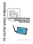
1
INSTRUCTION MANUAL
RF400/RF410/RF415 Spread
Spectrum Data Radio/Modem
Revision: 3/05
C o p y r i g h t ( c ) 2 0 0 1 - 2 0 0 5
C a m p b e l l S c i e n t i f i c , I n c .
Warranty and Assistance
The RF400 SERIES SPREAD SPECTRUM DATA RADIO/MODEMS are
warranted by CAMPBELL SCIENTIFIC, INC. to be free from defects in
materials and workmanship under normal use and service for twelve (12)
months from date of shipment unless specified otherwise. Batteries have no
warranty. CAMPBELL SCIENTIFIC, INC.'s obligation under this warranty is
limited to repairing or replacing (at CAMPBELL SCIENTIFIC, INC.'s option)
defective products. The customer shall assume all costs of removing,
reinstalling, and shipping defective products to CAMPBELL SCIENTIFIC,
INC. CAMPBELL SCIENTIFIC, INC. will return such products by surface
carrier prepaid. This warranty shall not apply to any CAMPBELL
SCIENTIFIC, INC. products which have been subjected to modification,
misuse, neglect, accidents of nature, or shipping damage. This warranty is in
lieu of all other warranties, expressed or implied, including warranties of
merchantability or fitness for a particular purpose. CAMPBELL SCIENTIFIC,
INC. is not liable for special, indirect, incidental, or consequential damages.
Products may not be returned without prior authorization. The following
contact information is for US and International customers residing in countries
served by Campbell Scientific, Inc. directly. Affiliate companies handle repairs
for customers within their territories. Please visit www.campbellsci.com to
determine which Campbell Scientific company serves your country. To obtain
a Returned Materials Authorization (RMA), contact CAMPBELL
SCIENTIFIC, INC., phone (435) 753-2342. After an applications engineer
determines the nature of the problem, an RMA number will be issued. Please
write this number clearly on the outside of the shipping container.
CAMPBELL SCIENTIFIC's shipping address is:
CAMPBELL SCIENTIFIC, INC.
RMA#_____
815 West 1800 North
Logan, Utah 84321-1784
CAMPBELL SCIENTIFIC, INC. does not accept collect calls.
– CAUTION –
Where an AC adapter is used, CSI recommends
Item # 15966. This AC adapter is included as part of
Item # 14220 RF400 Series Base Station Cable/Power Kit.
Any other AC adapter used must have a DC output not
exceeding 16.5 Volts measured without a load to avoid
damage to the RF400 Series radio!
Over-voltage damage is not
covered by factory warranty!
(See Power Supplies, Section 4.2 for AC adapter requirements)
Power plug polarity
This is a blank page.
RF400 Series Table of Contents
PDF viewers note: These page numbers refer to the printed version of this document. Use
the Adobe Acrobat® bookmarks tab for links to specific sections.
1. Introduction.................................................................1
2. RF400 Series Specifications ......................................2
3. Quick Start ..................................................................3
4. System Components ..................................................7
4.1 RF400 Series Data Radio..........................................................................7
4.1.1 Indicator LEDs................................................................................7
4.1.2 Setup Menu .....................................................................................8
4.1.3 Networking......................................................................................9
4.1.4 Error Handling and Retries ...........................................................10
4.1.5 Received Signal Strength ..............................................................12
4.2 Power Supplies .......................................................................................12
4.3 Serial Cables ...........................................................................................14
4.4 Antennas for the RF400 Series ...............................................................15
4.5 Antenna Cables and Surge Protection.....................................................19
4.5.1 Antenna Cables .............................................................................19
4.5.2 Electro-static Issues.......................................................................19
4.5.3 Antenna Surge Protector Kit .........................................................20
5. Software Setup..........................................................21
5.1 Point-to-Point..........................................................................................21
5.2 Point-to-Multipoint .................................................................................21
5.3 Example Setups.......................................................................................21
5.3.1 Direct PC to RF400 Series Base Station Setup .............................21
5.3.2 Remote Station Setup ....................................................................23
5.3.3 LoggerNet Configuration ..............................................................25
5.3.4 PC208W Configuration.................................................................26
6. Troubleshooting........................................................28
Appendices
A. Part 15 FCC Compliance Warning......................... A-1
B. Setup Menu ............................................................ B-1
i
RF400 Table of Contents
C. RF400 Series Address and Address Mask ........... C-1
D. Advanced Setup Standby Modes ......................... D-1
E. RF400 Series Port Pin Descriptions ..................... E-1
F. Datalogger RS-232 Port to RF400 Series Radio ... F-1
G. Short-Haul Modems ...............................................G-1
H. Distance vs. Antenna Gain, Terrain, and
Other Factors ..................................................... H-1
I. Phone to RF400 Series ............................................. I-1
J. Monitor CSAT3 via RF400 Series............................J-1
K. Pass/Fail Tests ....................................................... K-1
L. RF400/RF415 Average Current Drain
Calculations ....................................................... L-1
Figures
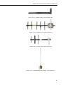
1. RF400......................................................................................................... 2
2. RF400 Basic Point-to-Point Network......................................................... 5
3. Point-to-Point LoggerNet Network Map.................................................... 6
4. Some 900 MHz FCC Approved Antennas .......................................... 16-18
5. Example COAX RPSMA-L Cable for Yagi or Omni Colinear................ 19
6. Antenna Surge Protector .......................................................................... 19
7. Enclosure with Antenna Surge Protector for RF400 ................................ 20
8. Point-to-Multipoint System ...................................................................... 26
9. PC208W Datalogger Generic Dial String ................................................ 27
G-1. Short-Haul Modem to RF400 Setup................................................... G-1
I-1. LoggerNet Point-to-Multipoint Setup....................................................I-4
K-1. Loop-back Test without Antennas...................................................... K-3
K-2. Vertically Polarized 9 dBd 900 MHz Yagi ........................................ K-5
K-3. 3 dBd 900 MHz Collinear Omni Antenna.......................................... K-6
Tables
1. Lacking 12 V on CS I/O Pin 8 ................................................................... 5
2. Standard Setup Menu ................................................................................. 8
3. 15966’s Voltage Regulation..................................................................... 14
4. RF400 Series 12 V Power Supply Options .............................................. 14
D-1. Advanced Setup Menu ....................................................................... D-1
H-1. 900 MHz Distance vs. Path Loss (Lp in dB) per Three Path Types .. H-6
H-2. Path Type vs. Path Characteristics Selector ....................................... H-6
ii
RF400 Table of Contents
K-1. 900 MHz Gain Antenna Test Distances..............................................K-6
L-1. Advanced Setup Menu ........................................................................ L-1
iii
RF400 Table of Contents
This is a blank page.
iv
RF400 Series Spread Spectrum Data
Radio/Modems
1. Introduction
This manual covers the RF400 series radios — the RF400, RF410, and RF415.
These radios differ from one another primarily in the radio frequencies at
which they communicate. In this manual the term “RF400” can refer to the
“RF400 series” or to that specific model. For clarity we will sometimes add
“900 MHz.”
The RF400 is a 900 MHz, frequency hopping, spread spectrum, data
radio/modem for point-to-point and point-to-multipoint communications. An
excellent receiver combined with 100 mW transmitter power make possible,
depending on path specifics, communication distances of 1/4 to 5 miles using
omni-directional antennas and 10 to 20 miles using 9 dBd directional antennas
(see Appendix H for a discussion of antenna gain and other factors affecting
distance).
The RF410 differs from the RF400 in that it operates at 922 MHz for regions
such as Australia, New Zealand, and Israel. The RF410’s communication
range is the same as that of the RF400.
The RF415 is a 2.4 GHz version with 50 mW transmitter intended mainly for
certain European and Asian markets. Communication distances vary from 300
feet (indoors) to ¼ mile (100 to 400 meters) with omni-directional antennas to
over 12 miles (19 kilometers) with gain antennas and optimal terrain.
Users do not normally need a communications authority license for the RF400
series configurations described in this manual including U.S. Government
Agencies regulated by NTIA Annex K. The 900 MHz and 2.4 GHz bands are
shared with other non-licensed services such as cordless telephones and with
licensed services including emergency, broadcast, and air-traffic control, so
band usage will vary from location to location as will man-made noise. Spread
spectrum technology resists noise and interference; however, the user may
wish to test communications on site using Quick Start (Section 3) before
committing to its use.
The RF400 operates from a 12 VDC power supply. The RF400’s low standby
current modes allow it to operate at remote sites on small power budgets.
The RF400 was designed for ease of installation. It works in many
applications “out of the box” with default settings.
1
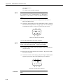
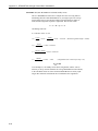
RF400 Series Spread Spectrum Data Radio/Modems
FIGURE 1. RF400
The RF400 has a 9-pin serial CS I/O port and a 9-pin serial DCE RS-232 port.
The CS I/O port allows the RF400 to connect to a datalogger. The RS-232 port
allows direct PC connection for Setup Menu access and to create a direct
connect RF400 “base station” for point-to-point and point-to-multipoint
communications. Where necessary, a more distant base station can be set up
using short-haul modems or phone modems between PC and RF400.
Base Station power is usually provided by a wall adapter. For a remote RF400,
power is normally provided by the datalogger.
A PC running LoggerNet, PC208W, or PC208 is used for data collection,
program transfer, and other datalogger supported functions. The PakOS
software or a terminal program is used to configure the RF400 radios.
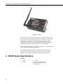
2. RF400 Series Specifications
POWER
•
•
2
Voltage
Current
9 – 18 VDC
75 mA typical during transmit
24 mA typical receiving a signal
(36 mA for RF415)
RF400 Series Spread Spectrum Data Radio/Modems
Quiescent Current in Standby Modes*
Avg. Quiescent
Advanced Setup
Current (mA)
Standby Mode
RF400/
RF410
RF415
24.0
33.0
0 (no duty cycling)
3.9
5.5
3
2.0
2.8
4
1.1
1.5
5
0.64
0.84
6
0.40
0.50
7
* Not receiving a signal nor transmitting
Standard
Setup
1
2
3
4
PHYSICAL
•
•
•
•
Size
Weight
Operating temp. range
Humidity
4.75 x 2.75 x 1.3 inches (12.1 x 7.0 x 3.3 cm)
0.5 lbs (225 g)
–25°C to +50°C
0 to 95% RH, non-condensing
RF/INTERFACE
•
Transceiver modules
•
Frequency bands
•
Interface ports
•
•
I/O Data Rates
Mode
•
•
•
Channel capacity
Transmitter output
Receiver sensitivity
•
•
Antenna impedance
Interference reject
•
•
RF packet size
Error handling
MaxStream
RF400 – 9XStream XO9-009
RF410 – 9XStream XH9-009
RF415 – 24XStream X24-009
RF400 – 910.5 to 917.7 MHz
RF410 – 920.0 to 927.2 MHz
RF415 – 2.45015 to 2.45975 GHz
1) CS I/O 9 pin
2) RS-232 9-pin (4 wire: Tx, Rx, CTS, GND)
38.4 K, 19.2 K, 9600, 4800, 1200 bps
Frequency hopping spread spectrum (FHSS), 25
hop channels, 7 hopping sequences, direct FM
frequency control
65,535 addresses
100 mW nominal (50 mW RF415)
−110 dBm at 10-4 bit error rate
(−104 dBm for RF415)
50 Ω, unbalanced (SMA male connector)
70 dB at pager and cellular phone frequencies
(RF400/RF410)
up to 64 bytes, half-duplex
RF packet CRC failure detection/rejection or
configurable retry levels
3. Quick Start
This section is intended to serve as a “primer” enabling you to quickly build a
simple system and see how it operates. This section describes in four steps
how to set up a pair of RF400s in a direct connect, point-to-point network. We
recommend that you do this before undertaking field installation. For
additional help on point-to-point networks and for help on creating point-tomultipoint networks, refer to Software Setup Section 5.
3
RF400 Series Spread Spectrum Data Radio/Modems
For this system you will need the following hardware or the equivalent:
1.
2.
3.
4.
5.
6.
7.
Two RF400s
Two RF400 antennas
AC adapter (Item # 15966 or part of kit #14220)
Serial cable (6 ft.) for PC COM port to RF400 RS-232 port (Item # 10873
or part of Item # 14220)
SC12 cable (included with RF400)
Datalogger (CR10X, CR510, or CR23X)
Field Power Cable (Item # 14291) if datalogger or wiring panel doesn’t
have 12 V on pin 8 of CS I/O port
You will also need:
1.
2.
An IBMTM compatible PC with one available COM port
LoggerNet or PC208W installed
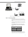
Step 1 – Set Up Base RF400
4
a.
Connect an antenna (or antenna cable with yagi or omni directional
antenna attached) to the RF400 antenna jack. Any RF400 antenna will
work at close range in any orientation. The main objective is to provide
an antenna. If you should transmit without an antenna attached, there will
be no equipment damage as the transmitter is protected against load
mismatch. The separation between the base RF400 antenna and the
remote RF400 antenna can be any convenient distance.
b.
Connect 6 ft. serial cable from PC COM port to base RF400 RS-232 port.
c.
Plug AC adapter into AC outlet and plug barrel connector into base
RF400 “DC Pwr” jack. You will see the red “Pwr/TX” LED light
immediately followed by the green RX LED in about 5 seconds. The
green LED goes off after a second and the red after ten seconds indicating
a successful power-up. The red LED then begins to flash on and off. The
red LED flashes once every half second in the default “< 4 mA, ½ sec
Cycle” standby mode as the RF400 wakes up briefly and listens for RF
transmissions with an average current consumption less than 4 mA.
d.
Use default settings of RF400.
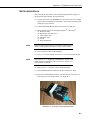
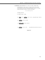
RF400 Series Spread Spectrum Data Radio/Modems
AC Adapter
apx
TECHNOLOGIES INC.
HICKSVILLE, NEW YORK
CLASS 2 TRANSFORMER
MODEL NO: INPUT:
OUTPUT:
UL
R
AP2105W
120VAC 60Hz 20W
12VDC 1.0A
LISTED
2H56
E144634
UL
R
MADE IN CHINA
RS-232
DC
Pwr
Logan, Utah
RF400
RS232
Spread Spectrum Radio
CS I/O
This device contains transmitter module:
FCC ID: OUR-9XTREAM
The enclosed device complies with Part 15 of the
FCC Rules.
Program
Operation is subject to the following two conditions:
(1) This device may not cause harmful interference,
and (2) this device must accept any intererence
Pwr/TX
received, including interference that may cause
Antenna
RX
undesired operation.
Serial #
14320
MADE IN USA
LoggerNet or PC208W
Datalogger CS I/O
Logan, Utah
SW 12V CTRL
7
SE
DIFF
RS232
RF400
8
9
L
AG H
G
H
10
11 12
6
L AG E3
5
4
G
DC
Pwr
Logan, Utah
L
AG H
SW 12V
AG G
G
5V 5V G
CS I/O
G 12V
POWER
IN
CS I/O
G
CR10X WIRING PANEL
MADE IN USA
Spread Spectrum Radio
CS I/O
This device contains transmitter module:
FCC ID: OUR-9XTREAM
SE
DIFF
1
2
3
L
AG H
G
H
4
5
L
AG H
2
1
G
The enclosed device complies with Part 15 of the
6
SDM
3
L
AG E1
AG E2 G
P1 G
P2 G C8 C7 C6 C5 C4 C3 C2 C1 G 12V 12V
FCC Rules.
Program
EARTH
GROUND
Operation is subject to the following two conditions:
(1) This device may not cause harmful interference,
and (2) this device must accept any intererence
Pwr/TX
received, including interference that may cause
Antenna
RX
undesired operation.
Serial #
14320
WIRING
PANEL NO.
MADE IN USA
FIGURE 2. RF400 Basic Point-to-Point Network
Step 2 – Set Up Remote RF400
a.
Connect an antenna (or antenna cable with yagi or omni directional
antenna attached) to the RF400 antenna jack. The separation between the
base RF400 antenna and the remote RF400 antenna can be any convenient
distance.
b.
Connect SC12 serial cable from datalogger CS I/O port to remote RF400
CS I/O port. Current datalogger/wiring panel CS I/O ports apply power to
the remote RF400.
With older dataloggers lacking 12 V on pin 8 (see Table 1), you can
power the RF400 using a Field Power Cable (see above hardware list)
between the datalogger’s 12 V (output) terminals and the RF400’s “DC
Pwr” jack.
TABLE 1. Lacking 12 V on CS I/O Pin 8
EQUIPMENT
CR500
CR7 700X Bd.
21X
CR10 Wiring Panels
PS512M Power Supply
SERIAL NUMBER
< 1765
< 2779
< 13443
All (black, gray, silver)
< 1712
When you connect power to the RF400 (through the SC12 cable or the
optional Field Power Cable) you should see the power-up sequence of red
and green LEDs described in Step 1 (assuming datalogger is powered).
5
RF400 Series Spread Spectrum Data Radio/Modems
Current dataloggers and wiring panels (not mentioned in Table 1) provide
12 V on pin 8. For older products not listed, check for 12 V between CS
I/O connector pin 8 and pin 2 (GND) or contact Campbell Scientific.
c.
Use default settings of RF400.
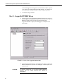
Step 3 – LoggerNet/PC208W Set-up
a.
The next step is to run LoggerNet/PC208W and configure it to connect to
the datalogger via the RF400 point-to-point network you have set up. The
RF400 in a point-to-point network can operate transparent to
LoggerNet/PC208W. Simply add a datalogger to a COM port in the
Device Map.
FIGURE 3. Point-to-Point LoggerNet Network Map
b.
CAUTION
6
Set the Maximum Baud Rate for 9600 baud which is the rate at which the
RF400 communicates by default. The datalogger “Extra Response Time”
can be left at 0.
For safety, maintain 20 cm (8 inches) distance between
antenna and any nearby persons while RF400 is
transmitting.
RF400 Series Spread Spectrum Data Radio/Modems
Auto Sense
The RF400 has a default feature called “Auto Sense” that automatically
configures certain RF400 settings. When you connect an RF400 to a
datalogger (CS I/O port to CS I/O port) the RF400 detects the presence of the
datalogger and makes its CS I/O port the active port. When you are not
connected to a datalogger’s CS I/O port, Auto Sense detects that and
configures its RS-232 port as the active port and configures certain other
settings so it can serve as a base RF400.
For point-to-point networks Auto Sense and default settings take care of
everything. An exception to this is where you have a neighboring network that
is also using the default RF400 settings. In this case, refer to Software Setup
Section 5 and change your RF400s to a hopping sequence different than the
default settings of “0” (zero). For this point-to-point network, configure both
RF400s the same.
Radio Address
Each RF400 has a “Radio Address” that can be changed by the user. In order
for two RF400s to communicate, their radio addresses must be set to the same
number. The RF400’s factory default radio address is “0” (zero) so a pair of
RF400s will be able to communicate out of the box (their network addresses
and hopping sequences are also “0” (zero) by default). See Section 4.1.3.1 and
Section 5 (Software Setup) for more details.
Step 4 – Connect
You are now ready to Connect to your datalogger using the
LoggerNet/PC208W Connect screen. After you connect, notice the flashing of
the green LEDs on both RF400s. This indicates that RF packets with the same
hopping sequence are being received by the RF400s. The red LEDs light solid
while the connection lasts. When you Disconnect, the red LEDs remain on for
five seconds, which is the default setting of the “Time of Inactivity to Sleep.”
Datalogger program transfer and data collection are now possible. Refer to
Appendix H for a treatment of communication distance vs. factors in the RF
path.
4. System Components
4.1 RF400 Series Data Radios
4.1.1 Indicator LEDs
The RF400 has a red LED labeled “Pwr/TX” and a green LED labeled “RX.”
When 12V power is applied the red LED lights for ten seconds. About 5
seconds after power-up the green LED lights for a second. Ten seconds after
power-up the selected standby mode begins to control the red LED. The red
LED lights to indicate when the receiver is actively listening. When the
receiver detects RF traffic (header or data with the same hopping sequence),
the red LED will light steadily. When the RF400 is transmitting, the red LED
will pulse OFF as the RF packets are transmitted (it will not be on solid).
7
RF400 Series Spread Spectrum Data Radio/Modems
Green LED activity indicates that there is an RF signal being received whose
hopping sequence corresponds to the configured hopping sequence of the
RF400. This does not necessarily mean that the network/radio address of the
received packet corresponds with that of the RF400 (where a neighboring
network exists it is a good idea to choose a unique hopping sequence).
4.1.2 Setup Menu
The RF400 has a built-in Setup Menu for configuring active interface, RS-232
properties, network/radio addresses, hopping sequence, power saving (standby)
modes, address masks, and other parameters. The Setup Menu is accessed by
connecting the radio’s RS-232 port to a PC running a terminal program such as
TM
TM
Hyper Terminal or Procomm (always 9600 baud, 8-N-1) and pressing the
“Program” button on the RF400 for one second. Changed settings are saved in
flash memory by selecting menu item “5” as you exit the Setup Menu. If left
idle, the Setup Menu will time out 60 seconds after the last received character
and exit without saving any parameter changes with the message “Config
Timeout.” A datalogger can remain connected to the CS I/O port while setting
RF400 parameters on the RS-232 port, although CS I/O communications
would be inactive until exiting the Setup Menu.
4.1.2.1 Auto Sense
The factory default setting for Active Interface is “Auto Sense.” It is designed
to automatically configure an RF400’s port and radio address mask for
common user situations. When selected, Auto Sense determines whether or
not a datalogger (or PS512M null modem) is connected to the RF400 by
monitoring for 5 V on CS I/O pin 1. If 5 V is present, Auto Sense selects the
RF400’s CS I/O port and a radio address mask appropriate for a remote station.
Not finding 5 V on CS I/O pin 1, Auto Sense selects the RS-232 port and a
radio address mask appropriate for a base station (see Section 4.1.3.1 and
Appendix C for more information on radio address masks).
4.1.2.2 Standby Modes
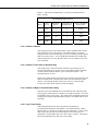
The RF400’s average idle current can be set with the following Standby Modes
(default setting shaded):
TABLE 2. Standard Setup Menu
Duty
Cycle
Standby
Mode
Menu
Selection
Advanced
Standby
Mode
Avg.
Receive
Current
Wake-up
Interval
(red LED
flash interval)
Maximum
Response
Delay*
100%
1
0
< 24 mA
0 sec (constant)
100 mS
17%
2
4
< 4 mA
½ sec
600 mS
4%
3
6
< 2 mA
1 sec
1100 mS
2%
4
7
< .4 mA
8 sec
8100 mS
*Maximum time it takes to get an RF Packet sent and for the other RF400 to respond.
8
RF400 Series Spread Spectrum Data Radio/Modems
The Standard Setup standby modes automatically configure:
•
•
•
Time of Inactivity to Sleep
Time of Inactivity to Long Header
Long Header Time
The default mode is the Standard Setup menu selection “2” for “< 4 mA and ½
sec Cycle.” There are standby modes available in addition to those in the
above table. They can be accessed in the Advanced Setup menu; however, if
you configure one of those, it will be necessary to also configure each of the
three bulleted parameters above. In any case, be sure to select the same
Standby Mode for all of the RF400s in the network. For more details see
Appendix D.
4.1.3 Networking
The RF400 acts as a transparent radio link. Each radio has a configurable
network address, radio address, and hopping sequence, and only radios that
have the same network address, radio address, and hopping sequence will
receive each other’s transmissions. The exception to this is that an RF400 base
station can receive packets from multiple remote station’s if the base station’s
Radio Address Mask is other than the maximum allowed number of 3ffh
(hexadecimal). When Auto Sense is selected, it sets the Radio Address Mask
to 0h if no 5 V is detected on its CS I/O port pin 1 (see Auto Sense Section
4.1.2.1).
4.1.3.1 Address and Address Mask
For simple point-to-point installations the RF400’s default settings (including
address settings) should work unless there is a neighboring network which uses
default settings. In that case the network address and, preferably, your hopping
sequence should be set to different numbers than the neighboring network uses.
A different network number is sufficient but a different hopping sequence
(there are 7 available) will result in fewer retries.
The RF400 has a two-part address. When the RF400’s Radio Address is
appended to its Network Address you have the complete 16-bit address.
Network Address
(0 – 63)
(0 - 11,1111)
(3f)
Radio Address
(0 – 1023)
(0 - 11,1111,1111)
(3ff)
decimal
binary
hexadecimal
When an incoming packet arrives from another RF400 using the same hopping
sequence, the receiving RF400 compares the packet header’s 16-bit address to
its own 16-bit address. If they match, and there are no packet errors, the
receiving RF400 sends the packet data to the configured active port (CS I/O or
RS-232). This assumes a receiving RF400 address mask of ffffh. If other than
ffffh (1111,1111,1111,1111 binary), only those address bits that correspond to
address mask “1” bits will be used in the comparison. See Appendix C for
details.
9
RF400 Series Spread Spectrum Data Radio/Modems
4.1.3.2 ATDT Command Mode
This mode is not required for basic point-to-point communication.
For point-to-multipoint operation the RF400 can temporarily be put into AT
Command Mode by sending a string of three ASCII characters. The default
sequence to enter AT Command mode is:
1.
2.
3.
4.
No characters sent for one second (before command character)
“+++”characters sent (default command mode entry character)
No characters sent for one second (after command mode character)
RF400 responds by sending “OK” <CR>
The AT Command mode characters are sent by PC208W along with other
commands to change the base RF400’s Radio Address to talk to the desired
remote RF400 (see point-to-multipoint example in Software Setup Section).
4.1.3.3 Combination Mode Communications
Besides the “direct” to PC communications described in the Quick Start and
Installation sections, it is possible to combine methods in datalogger
communications. Some examples:
•
Phone to RF400: PC to external modem to COM210 w/PS512M to RF400
to datalogger (see Appendix I)
•
Short Haul modem to RF400: PC to short haul modems to RF400s to
datalogger (see Appendix G)
•
Network to RF400: PC to Internet to NL100 to RF400 to datalogger (use
LoggerNet IPPort or PC208W socket, remote IP address, port number)
4.1.4 Error Handling and Retries
In the RF module received packets are analyzed for data corruption with an
embedded CRC. The RF400 rejects a received packet (doesn’t send it out a
port) if the packet’s header address fails to match the RF400 address, if an RF
module receive error is detected, or if the RF packet’s CRC test fails.
In early RF400s no notification was given when a packet was rejected, and
there were no retries nor guaranteed delivery of packets. Retries were handled
by protocols in LoggerNet and PC208W. Starting with SW Version 6.420 the
RF400 series radios themselves are capable of doing retries in a network with
an unlimited number of array-based stations or in a network consisting of two
PakBus stations.
4.1.4.1 Standard Retry Levels
There are four pre-programmed Retry Levels available in the Standard Setup
menu. All RF400s in the network should be configured for the same Retry
Level. The default setting is “None.” The standard settings should satisfy
most application requirements. Further choices are available in the Advanced
Setup menu. All radios in a network should have the same “Maximum
10
RF400 Series Spread Spectrum Data Radio/Modems
Retries”, “Time-slots for Random Retry”, and “Bytes Transmitted before
Delay” settings.
STANDARD RETRY LEVELS
Menu
Retry
Level
Maximum
Retries
Time-Slots for
Random Retry
Bytes Transmitted
Before Delay
1
None
0
0
65535
2
Low
3
2
1000
3
Medium
6
3
1000
4
High
10
5
1000
4.1.4.2 Number of Retries
This setting specifies the maximum number of times an RF400 will re-send a
packet failing to get an ACK response. The default setting is zero which
inactivates retries. The allowable range is 0 to 255. Entering a number greater
than zero activates retries. A receiving RF400 responds to the sending radio
with an ACK packet for every RF packet that it receives, addressed to it, that
has a valid CRC.
4.1.4.3 Number of Time Slots for Random Retry
This setting is active when the Number of Retries is greater than zero. It
specifies the number of 38 ms time slots to create among which to randomly
re-send a packet which has failed to get an ACK packet response. The
allowable range is 0 to 255.
If packets are failing because of periodic noise or signals, specifying more time
slots for random retries will improve the chances for successful retry packet
delivery. Increasing the number of time slots, however, results in longer
average retry delays which could lower data throughput.
4.1.4.4 Number of Bytes Transmitted before Delay
This feature prevents an RF400 Series radio which has lots of data to transfer
from tying up a network until it is finished. The range of settings is 1 to 65535.
The default value is 65535 (bytes). This setting forces an RF400 to pause long
enough, after sending the specified number of bytes, for another radio to send
some data.
4.1.4.5 Sync Timer Setting
This setting determines how often sent packets will include hop
synchronization information in the headers. The default setting is 0 which
specifies that every packet will contain hop sync information. A value greater
than zero specifies the interval at which a packet will contain hop sync
information. The allowable range is 0 to 255 in units of 100 ms. All radios in
the network should have the same Sync Timer Setting.
11
RF400 Series Spread Spectrum Data Radio/Modems
For example, if you input a value of 50, then packets with hop sync info will be
sent out every 5 seconds improving (shortening) the response time of a
transmit/response sequence. Even though this shortens the time required to
send x amount of data, the throughput is still determined by the CS I/O or
RS-232 port baud rate setting.
4.1.4.6 Number of Retry Failures
This reading is available in Setup Menu/Advanced Setup/Radio
Parameters/Radio Diagnostics. It indicates the number of times that the RF400
has re-transmitted the specified Number of Retries but failed to get an ACK
packet from the receiving radio. For example, if the Number of Retries is set
to 3, the transmitting radio will send the same packet up to 3 times; each time
looking for an ACK packet back from the receiving radio. If it does not
receive an ACK packet after sending the packet 3 times, the transmitting radio
will increment its Number of Retry Failures count. If a radio is configured to
do retries, it will produce an ACK packet for every RF packet that it receives,
addressed to it, that has a valid CRC. If 0 retries are configured, the receiving
RF400 will simply throw away any packet that fails the CRC. This reading is
cleared upon exiting Setup Menu or cycling RF400 12 V power.
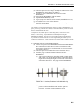
4.1.5 Received Signal Strength
Beginning with SW Version 6.420 the RF400 series radios provide a means of
knowing the signal strength of the last packet received, addressed to it, that had
a valid CRC. To see this reading enter the RF400’s Setup Menu /Advanced
Setup/Radio Parameters/Radio Diagnostics menu. RSS readings are cleared
upon exiting the Setup Menu or cycling the RF400’s 12 Volt power.
The RSS reading is a relative signal level indication expressed in dB (decibels).
Readings may vary up to 10 dB from radio to radio for a given received signal
level. The weakest signal reading is around 25 dB and the strongest signal
reading is near 86 dB. Although the RSS readings are not absolute, they will
be of value in such activities as:
•
determining the optimal direction to aim a yagi antenna
•
seeing the effects of antenna height, location
•
trying alternate (reflective) paths
•
seeing the effect of seasonal tree leaves
4.2 Power Supplies
The typical base station RF400 connected directly to a PC uses a 120 VAC
wall adapter to supply 12 VDC power. You can order the optional Base
Cable/Power Kit (CSI Item # 14220) to obtain the wall adapter with 6 ft. serial
cable. In a phone to RF400 base station configuration (without datalogger) the
RF400 can obtain power from a PS512M null modem.
The typical remote RF400 will be connected to a datalogger CS I/O port and
get its 12 V power from that. If your datalogger is an earlier unit without 12 V
on CS I/O pin 8 (see Table 1), there is an optional Field Power Cable available
12
RF400 Series Spread Spectrum Data Radio/Modems
(CSI Item # 14291) with tinned leads to connect to power at the datalogger 12
V output terminals and barrel connector to plug into the RF400’s “DC Pwr”
jack. If 120 VAC is available at the site, the 120 VAC adapter alone (CSI Item
# 15966) is an option.
A 12 V supply may connect to either the RF400’s “DC Pwr” jack or CS I/O pin
8 (or both, since there is diode isolation between supply inputs). The 12 V
supply inputs are diode protected against the application of reverse polarity
power.
CAUTION
There are many AC adapters available with barrel
connectors (plugs) that will fit the RF400. Some of these
(including the CSI AC adapter Item # 272) will cause
immediate damage if plugged into the RF400 even briefly.
It is also possible to damage the RF400 with an AC
adapter labeled as low as “12 VDC” because it may output
an open-circuit (no current drain) voltage exceeding the
maximum. The very low quiescent current (170 uA) of the
RF400 in its default and other standby modes allows the
supply voltage to rise at times virtually to its open-circuit
level.
The RF400 series radio will sustain damage if
the DC Pwr jack voltage ever exceeds 18
Volts!
120 VAC line voltages vary from location to location and
from time to time so observing a 16.5 VDC maximum is
wise. Unconsidered AC adapter selection raises the
specter of over-voltage damage to the RF400 and nonwarranty repairs!
There are several things to consider. Beware of AC
adapters outputting an AC voltage. An AC adapter can
output the correct voltage but the wrong polarity. The
center conductor of the barrel connector must be positive
(+). The AC adapter must also be capable of supplying the
instantaneous peak currents demanded by the RF400
transmitter. The best approach is to obtain the AC adapter
recommended by CSI (Item #15966 or the RF400 Base
Station Cable/Power Kit Item # 14220 which contains it). If
this is not possible, obtain an AC adapter that matches the
voltage vs. current characteristics shown below.
To be sure that the candidate AC adapter’s “no load” voltage is
below the 16.5 VDC recommended maximum, measure the
output with a DC voltmeter while the AC adapter is plugged into
the outlet but not powering anything.
13
RF400 Series Spread Spectrum Data Radio/Modems
CSI AC adapter Item # 15966 voltage regulation (typical) while plugged into
an AC outlet delivering 120.0 VAC:
TABLE 3. 15966’s Voltage Regulation
Current Drain
(mA)
0 (no load)
122
807
Resistive Load
(Ohms)
∞ (open circuit)
100 Ω
15 Ω
AC Adapter Output
(Volts)
12.22
12.20
12.11
The voltage regulation of the 15966 is exceptionally good.
Power connector polarity: inner conductor positive (+)
TABLE 4. RF400 Series 12 V Power Supply Options
Network
Role
RF400
Connection
Direct to PC
Base
Options — CSI Item #
− 14220 (with serial cable)
− 15966 (adapter only)
If 12V on pin 8*
CS I/O Port**
AC Adapter
Datalogger
PS512M
If no 12V on pin 8
Field Power Cable − 14291
AC Adapter − 14220 (in base cable/power kit)
− 15966 (adapter only)
PS512M null-modem connectors
If 12V on pin 8*
CS I/O Port
Remote
Datalogger
If no 12V on pin 8
Field Power Cable − 14291
AC Adapter − 14220 (in base cable/power kit)
− 15966 (adapter only)
* See Quick Start − Section 3, Step 2, Table 1
** If powering RF400 from CS I/O port but communicating via RS-232 port,
be sure to select “RS-232” as the Active Interface so CS I/O port is not auto
selected by Auto Sense.
4.3 Serial Cables
In an RF400 base station, a straight-through DB9M/DB9F RS-232 cable will
connect from the RF400’s RS-232 port to the PC COM port. This cable is part
of the optional Base Cable/Power Kit (CSI Item # 14220).
A remote RF400 normally uses the included SC12 cable to connect the
RF400’s CS I/O port to the datalogger’s CS I/O port.
14
RF400 Series Spread Spectrum Data Radio/Modems
A remote RF400 can be connected to a CR23X’s or CR5000’s RS-232 port
with a null modem DB9M/DB9M cable (CSI Item # 14392). See Appendix F
for details on power supply.
4.4 Antennas for the RF400 Series
Several antennas are offered to satisfy the needs for various base station and
remote station requirements. These antennas have been tested at an authorized
FCC open-field test site and are certified to be in compliance with FCC
emissions limits. All antennas (or antenna cables) have an SMA female
connector for connection to the RF400. The use of an unauthorized antenna
could cause transmitted field strengths in excess of FCC rules, interfere with
licensed services, and result in FCC sanctions against user.
NOTE
An FCC authorized antenna is a REQUIRED component. You
must pick one of the antennas listed below.
CSI Item Number
Description
14310
0 dBd ANTENNA, 900 MHZ, OMNI ¼ WAVE WHIP,
RPSMA STRAIGHT, LINX, 3.2 inches long.
14204
0 dBd ANTENNA, 900 MHZ, OMNI ½ WAVE WHIP,
RPSMA RT ANGLE, ASTRON, 6.75 inches long.
14221
3 dBd ANTENNA, 900 MHZ, OMNI COLLINEAR,
ANTENEX FG9023, 24 inches tall, W/FM2 MOUNTS,
fits 1 in. to 2 in. O.D. mast (requires COAX RPSMA-L
or COAX NTN-L)
15970
1 dBd ANTENNA, 900 MHZ, INDOOR OMNI ½
WAVE DIPOLE, 10 ft. cable with SMA connector to fit
RF400 Series, window or wall mounted by sticky back,
4 inches wide.
14205
6 dBd ANTENNA, 900 MHZ, YAGI, LARSEN
YA6900 TYPE N-F, boom length 17.25 inches, longest
element 7.25 inches, W/MOUNTS, fits 1 in. to 2 in.
O.D. mast (requires COAX RPSMA-L or COAX NTNL)
14201
9 dBd ANTENNA, 900 MHZ, YAGI, MAXRAD
BMOY8905 TYPE N-F, boom length 21.4 inches,
longest element 6.4 inches, W/MOUNTS, fits 1 in. to 2
in. O.D. mast (requires COAX RPSMA-L or COAX
NTN-L)
16005
0 dBd ANTENNA, 2.4 GHz, OMNI ½ WAVE WHIP,
RPSMA RT ANGLE, LINX ANT-2.4-CW-RCT-RP,
4.5 inches long.
16755
13 dBd ANTENNA, 2.4 GHz, ENCLOSED YAGI,
allows vertical or horizontal polarization, MAXRAD
15
RF400 Series Spread Spectrum Data Radio/Modems
WISP24015PTNF, boom length 17 inches, diameter 3
inches, W/ END MOUNT to fit 1 to 2 in. O.D. mast
(requires either (1) COAX RPSMA-L for short runs or
(2) COAX NTN-L with Antenna Surge Protector Kit)
COAX RPSMA-L
LMR 195 ANTENNA CABLE, REVERSE POLARITY
SMA TO TYPE N MALE
COAX NTN-L
RG8 ANTENNA CABLE, TYPE N MALE TO TYPE
N MALE CONNECTORS, REQUIRES 14462
14462
ANTENNA SURGE PROTECTOR KIT
FCC OET Bulletin No. 63 (October 1993)
Changing the antenna on a transmitter can significantly increase, or decrease,
the strength of the signal that is ultimately transmitted. Except for cable
locating equipment, the standards in Part 15 are not based solely on output
power but also take into account the antenna characteristics. Thus, a low
power transmitter that complies with the technical standards in Part 15 with a
particular antenna attached can exceed the Part 15 standards if a different
antenna is attached. Should this happen it could pose a serious interference
problem to authorized radio communications such as emergency, broadcast,
and air-traffic control communications.
CAUTION
In order to comply with the FCC RF exposure
requirements, the RF400 series may be used only with
approved antennas that have been tested with this radio
and a minimum separation distance of 20 cm must be
maintained from the antenna to any nearby persons.
Read Appendix A of this manual for important FCC information.
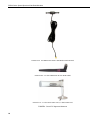
ITEM # 14310 900 MHZ OMNI ¼ WAVE WHIP 0 dBd
16
RF400 Series Spread Spectrum Data Radio/Modems
ITEM # 14204 900 MHZ OMNI ½ WAVE WHIP 0 dBd
ITEM # 14201 900 MHZ YAGI 9 dBd w/MOUNTS
ITEM #14205 900 MHz YAGI 6 dBd w/MOUNTS
ITEM # 14221 900 MHZ OMNI COLLINEAR 3 dBd w/MOUNTS
17
RF400 Series Spread Spectrum Data Radio/Modems
ITEM #15970 900 MHZ Indoor OMNI 1 dBd Window/Wall Mounted
ITEM #16005 2.4 GHz OMNI HALF WAVE WHIP 0 dBd
ITEM #16755 2.4 GHz ENCLOSED YAGI, 13 dBd w/MOUNTS
FIGURE 4. Some FCC Approved Antennas
18
RF400 Series Spread Spectrum Data Radio/Modems
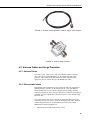
FIGURE 5. Example COAX RPSMA-L Cable for Yagi or Omni Colinear
FIGURE 6. Antenna Surge Protector
4.5 Antenna Cables and Surge Protection
4.5.1 Antenna Cables
The 14201, 14203, 14205, 14221, and 16755 antennas require an antenna
cable; either (1) the COAX RPSMA or (2) the COAX NTN with surge
protector. Indoor omni-directional antennas are either supplied with an
appropriate cable or connect directly to the RF400 series radio.
4.5.2 Electro-static Issues
Many RF400 series installations are out of doors and therefore susceptible to
lightning damage, especially via the antenna system. Also, depending on
climate and location, electro-statically charged wind can damage sensitive
electronics if sufficient electric charge is allowed to accumulate on the antenna
and cable. To protect against this CSI offers the Item # 14462 Antenna Surge
Protection Kit.
The COAX NTN-L cable is a low-loss RG8 coaxial cable that requires the
14462 surge protector in order to connect to an RF400 series radio. The RG8 /
Antenna Surge Protector are recommended in preference to the COAX
RPSMA in the following applications:
•
When the antenna cable length exceeds 10 feet
19
RF400 Series Spread Spectrum Data Radio/Modems
•
When use of COAX RPSMA would result in too much signal loss (see
page H-3)
•
When the RF400 series radio will be used in an environment susceptible to
lightning or electro-static buildup
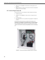
4.5.3 Antenna Surge Protector Kit
The Surge Protector Kit for the RF400 series radios includes the following:
•
Polyphaser protector
•
18 inches of COAX RPSMA to connect ‘tail end’ of surge protector to
RF400
•
Ground wire lead
•
Screw and grommet to secure ground wire and polyphaser to backplate of
enclosure
The surge protector has female type N connectors on both ends; one for
connection to the COAX NTN-L cable and the other for connection to the 18
inch length of COAX RPSMA cable included in the kit. The COAX RPSMA
cable is an LMR195 type that terminates in a type N Male connector on the
‘antenna end’ and a Reverse Polarity SMA (RPSMA) connector on the RF400
end.
FIGURE 7. Enclosure with Antenna Surge Protector for RF400
20
RF400 Series Spread Spectrum Data Radio/Modems
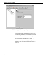
5. Software Setup
5.1 Point-to-point
Set-up parameters are configured the same for the two RF400s. The RF400
defaults to radio address “0” (zero) which works for many applications.
See Section 4.2 for power supply options.
5.2 Point-to-multipoint
The radio addresses for a base RF400 and its remotes are typically configured
to be different from one another. The base RF400 radio address might be 0,
the first remote’s radio address might be 1, and the second remote’s radio
address might be 2, etc.
For the base RF400 to be able to transmit to a remote RF400, the base’s Radio
Address must be temporarily changed to match that of the remote. The address
change is done by putting the base RF400 into command mode, changing the
address with an ATDT command, and then putting it back into data mode with
the ATCN command. You can accomplish this by entering these commands in
the Generic Dial String in PC208W’s datalogger Setup Connections screen (see
example below).
See Section 4.2 for power supply options.
5.3 Example Setups
The following procedures explain how to build a basic RF400 point-to-point
network and a point-to-multipoint network with base station connected directly
to the PC COM port. The PC should be running LoggerNet or PC208W. The
remote station can consist of an RF400 connected to a datalogger.
5.3.1 Direct PC to RF400 Series Base Station Setup
1.
Connect the RF400’s RS-232 port to a PC COM port using a straight
through serial cable Item # 10873, or equivalent. Use a 25-pin to 9-pin
adapter if necessary. This hardware configuration can serve (1) to do the
set-up of the RF400, and (2) for base station communications with
datalogger(s) in point-to-point or point-to-multipoint networks.
2.
Run Hyper TerminalTM, ProcommTM, or other terminal emulator program.
a.
c.
d.
e.
f.
3.
Baud rate: 9600, 8-N-1
Flow control: none
Emulation: TTY
ASCII (raw)
COM1 (direct connect)
Power up RF400 (wait two seconds) and press “Program” button for one
second to see the following display.
21
RF400 Series Spread Spectrum Data Radio/Modems
Main Menu
SW Version 6.425 (for example)
(1) Standard Setup
(2) Advanced Setup
(3) Restore Defaults
(4) Show All Current and Default Settings
(5) Save All Parameters and Exit Setup
(9) Exit Setup without Saving Parameters
Enter Choice:
4.
Press “1” for Standard Setup
Display:
Standard Setup:
Current Setting
(1) Active Interface
Auto Sense
(2) Net Address
0
(3) Radio Address
1
(Net + Radio Address 0h)
(4) Hopping Sequence 0
(5) Standby Mode
< 4 mA, ½ sec Cycle
(6) Retry Level
(9) Return to Main Menu
Enter Choice:
22
a.
Leave Active Interface in “Auto Sense” (default setting) for most
applications. In Auto Sense the RF400 will test for 5 V on CS I/O
port (pin 1) to determine if a datalogger is present and if so select the
CS I/O port.
b.
Select a Net Address from (0 – 63). Unless there is a neighboring
network, leave network address “0.” The Network Address must be
the same throughout the network of RF400s.
RF400 Series Spread Spectrum Data Radio/Modems
c.
Select a Radio Address (0 – 1023). The radio addresses must be the
same in point-to-point communications (for point-to-multipoint
communications you could set the base RF400 to 0 and the remotes to
1, 2, 3, etc.).
It is a good idea to label each RF400 indicating the configured
network address, radio address, hopping sequence, etc.
d.
Select a Hopping Sequence (0 – 6). The hopping sequence must be
the same for all RF400s in the network.
If there happens to be a neighboring RF400 network using the same
hopping sequence, you should change to a different one in case their
network and radio addresses happen to match yours and to reduce
retries.
- RX LED Test To determine if there is a neighboring RF400 network in operation
using the same hopping sequence as yours, stop communications on
your network and observe an RF400 green LED for activity. A
flashing green LED would indicate that there is a nearby network
using the same hopping sequence.
e.
Select desired Standby mode (< 24 mA Always on, < 4 mA ½ sec
Cycle, etc.) according to your power budget. All RF400s in the
network must be in the same Standby Mode. The default setting is a
good starting point (< 4 mA ½ sec Cycle).
f.
Select desired Retry Level (None, Low, Medium or High) according
to the level of RF ‘collisions’ you expect. This depends on how
many neighboring RF400s in and out of your network and the
frequency of transmissions. Retries can, for example, reduce pauses
in real-time monitoring of Input Locations.
g.
Press 9 to “Return to Main Menu”.
h.
There are other (“advanced”) parameters which typically remain
“default” or as set by Auto Sense.
i.
Press “5” to “Save All Parameters and Exit Setup.”
5.3.2 Remote Station Setup
1.
Point-to-point
a.
Complete steps 1 to 4 above making the remote station’s Network
Address, Radio Address, and Hopping Sequence the same as the base
station’s.
b.
While in Standard Setup verify that the Active Interface configuration
is “Auto Sense” and set the Standby Mode the same as the base
RF400 (default “2” ok).
c.
Exit and Save your configuration by pressing “5”.
23
RF400 Series Spread Spectrum Data Radio/Modems
2.
Point-to-multipoint
a.
Complete steps 1 to 4 above making the remote stations’ Network
Addresses and Hopping Sequences the same as the base station’s.
b.
While in Standard Setup verify that the active interface is “Auto
Sense” and give each remote RF400 a unique Radio Address.
You should label each RF400 (with masking tape) indicating the
configured network address, radio address, hopping sequence, etc.
c.
3.
Exit and Save your configuration by pressing “5”.
Antenna considerations
a.
Line of sight – the single most important factor in radio performance
is antenna placement. As Appendix H states, “height is everything.”
The two RF400s must be able to ‘see’ each other if distances over a
mile or two are required. This can be accomplished with a mast or
tower.
b.
Mounting – the higher the gain of a yagi antenna, the more important
it is to aim the yagi precisely and mount the yagi solidly to prevent
movement due to strong winds, large birds, etc.
c.
Antenna cable routing – the antenna cable should be routed in a
protected area and made secure against damage from wildlife, wind,
and vandalism.
d.
Antenna cable weather sealing – the presence of water inside the
antenna cable’s plastic sheath can attenuate your transmitted and
received signals significantly. The RF energy, instead of traveling
the length of the cable with little loss, is absorbed according to the
amount of water present (like in a microwave oven). A small amount
of water can ruin a once good communication link.
When moisture gets inside the sheath it is very difficult to remove.
Some careful cable handling (even pinholes can let in significant
amounts of water), thoughtful cable routing, and good weatherproofing can prevent this.
Apply a 1/8 inch thick coat of pure silicone rubber compound (RTV)
1) where the cable connector screws onto the antenna connector
(apply after the connector is in place allowing future removal) and
2) at the junction between plastic cable sheath and cable connector. If
carefully done this should last for years. An alternative approach is to
wrap self-vulcanizing rubber tape around these same areas of the
antenna connector, cable connector and cable sheath. This tape can
be purchased at most electrical supply stores (see Troubleshooting
Section 6, item 6).
4.
Site considerations
Location of an RF400 near commercial transmitters, such as at certain
mountaintop sites, is not recommended due to possible “de-sensing”
problems for the RF400 receiver. A powerful signal of almost any
frequency at close range can simply overwhelm a receiver. Lower
24
RF400 Series Spread Spectrum Data Radio/Modems
power and intermittent repeater sites may not be a problem. Test
such a site with a representative setup before committing to it (see
Troubleshooting Section 6). Keep in mind that commercial sites tend
to evolve. Such a site may work now but could change in the future
with the addition of new equipment.
5.3.3 LoggerNet Configuration
There are two ways of configuring the Setup map for a point-to-point
‘network.’ You can represent the RF400s in the Setup map or simply leave
them off. The simple map usually results in a quicker connection and requires
less typing.
(1) Point-to-point (not represented)
(a) Setup map:
ComPort_1
CR10X
(2) Point-to-point (represented)
(a) Setup map:
ComPort_1
RF400
RF400Remote
CR10X
(3) The station’s Maximum Baud Rate is typically 9600
(4) Extra Response Times are typically 0 s
In the case of point-to-multipoint, the RF400s are always represented in the
LoggerNet Setup map so that LoggerNet can temporarily change the base
RF400’s Radio Address to communicate with one out of a group of remote
RF400s.
(1) Point-to-multipoint
(a) Setup map:
ComPort_1
RF400
RF400Remote_1
CR10X_1
RF400Remote_2
CR10X_2
RF400Remote_3
CR10X_3
(2) All RF400Remotes have the same Network Address but each
RF400Remote must have a unique Radio Address.
(3) Extra Response Times are typically 0 s
25
RF400 Series Spread Spectrum Data Radio/Modems
3 dBd Omni Collinear
9 dBd Yagi
6 dBd Yagi
0 dBd Half-wave
CS I/O
CS I/O
CS I/O
RF400
RF400
DATALOGGER
DATALOGGER
RF400
RS-232
RF400
CS I/O
DATALOGGER
CS I/O
CS I/O
AC Adapter
FIGURE 8. Point-to-Multipoint System
5.3.4 PC208W Configuration
a.
Point-to-point
(1) Device Map -
COM1
CR10X1
(2) Set station CR10X1 baud rate to 9600 baud in network map
(3) Datalogger extra response time – 0 mS
b.
Point-to-multipoint
(1) Device Map -
COM1
Generic1
10X3001
10X3005
(2) Set Generic Modem baud rate to 9600 in device map.
(3) Generic Modem Settings
(a) √ “Make DTR Active”
(b) √ “Hardware Flow Control”
(c) Extra Response Time (Standby Mode Max Response Delay +
200 ms; see Table D-1)
(i) 0 mS with 24 mA Standby Mode
(ii) 1200 mS with 1/2 sec cycle default Standby Mode delay
(iii) 4200 mS with 2 sec cycle Standby Mode delay
26
RF400 Series Spread Spectrum Data Radio/Modems
(4) Datalogger Station Settings
(a) Example “Dialed Using Generic Dial String”:
D1000 T"+++" R"OK"9200 T"ATDT3001^m"R"OK"1200
T"ATCN^m"R"OK"1200
(i) D1000 creates a 1 second delay
(ii) T sends quoted string w/o waiting for a character echo
(iii) +++ is string sent to put RF400 in AT Command mode
(use other character if phone modems in path)
(iv) R”OK”9200 waits up to 9.2 sec for RF400 “OK” response
(v) ATDT3001 changes radio address to talk to remote RF400
with network address of 12 and radio address of 1. This is a
hexadecimal number (see Appendix C for example
combined hexadecimal network/radio addresses) and is
calculated by Setup Menu at Main Menu, Standard Setup,
Radio Address.
(vi) ATCN ends RF400 AT Command mode
(b) Datalogger extra response time – 0 mS
FIGURE 9. PC208W Datalogger Generic Dial String
27
RF400 Series Spread Spectrum Data Radio/Modems
6. Troubleshooting
If you can’t connect, check out these possible causes:
1.
Datalogger or Wiring Panel lacks 12 V power on pin 8 of CS I/O port
The RF400 should go through its initialization with red and green LEDs
lighting (see Section 4.1.1) when serial cable is connected if 12 V is
present on CS I/O connector (see Quick Start Table 1). If needed obtain
the optional Field Power Cable (CSI Item # 14291) to connect between
datalogger 12 V output terminals and RF400 “DC Pwr” jack to supply
power to the RF400.
2.
Active Interface set wrong
This setting should normally be “Auto Sense” unless you have a phone to
RF400 base station with PS512M and COM210 which requires the
“COM2xx to RF400” setting or you have a PakBus datalogger requiring
“Datalogger CSDC” due to another M.E. peripheral present. You could
set the Active Interface to RS-232 or Datalogger Modem Enable if that is
its permanent assignment, otherwise “Auto Sense” may be better.
3.
Low or weak battery voltage or 12 VDC supply voltage
The power supply battery may not be charging properly due to solar panel
orientation, poor connection, or due to a charging transformer problem.
The battery itself may have discharged too low too many times, ruining
the battery. Lead acid batteries like to be topped off.
Power supply must be able to sustain at least 9.6 V (datalogger minimum)
even during 75 mA transmitter bursts lasting only a few milliseconds.
4.
Lightning damage to RF400
Swap in a known good RF400 with the same settings and see if this cures
the problem. Lightning damage can occur leaving no visible indications.
A “near miss” can cause damage as well as a more direct hit with
evidence of smoke (see Appendix K for pass/fail tests).
5.
Lightning damage to antenna and/or cable
Swap in a known good antenna and/or cable. Hidden damage may exist.
6.
Moisture in coaxial antenna cable
It is possible that moisture has penetrated inside the plastic sheath of the
coaxial cable. Water inside the cable can absorb RF energy and attenuate
the transmitted signal; the received signal would also be attenuated. It is
difficult to dry out the interior of a coaxial cable. Substitution of a dry
cable is recommended.
Placing a wet cable in a conventional oven at 160°F for a couple of hours
should dry it out. Shield the antenna cable against damage from radiated
heat from the oven element by placing the coiled cable on a large cookie
sheet or a sheet of aluminum foil. See section 5.3.2 (3.d) for information
on weatherproofing the antenna cable.
28
RF400 Series Spread Spectrum Data Radio/Modems
7.
RF400 receiver “de-sensing” from nearby transmitter
This problem can be observed from LED behavior when operating a handheld radio near an RF400 that is receiving collected data from a remote
station. If you key a hand-held 150 MHz or 450 MHz transmitter, even
though its frequency of operation is far removed from the 900 MHz band,
its close proximity to the base RF400 can overwhelm (de-sense) the
RF400 receiver resulting in failed packets and LoggerNet/PC208W
retries. This problem could also occur if you located an RF400 at a site
containing commercial transmitters or repeaters. In general it is best to
avoid such sites, especially the high-power FM or AM transmitter antenna
sites which can change at any time with added equipment.
It is possible to avoid de-sensing in some cases if RF400 link is solid
enough due to: the proximity of your remote RF400(s); high antenna gains
and directionality; high elevation; and sufficient distance separation
between RF400 and commercial transmitter antenna. Try horizontal
polarization of antennas. A field test in such situations is essential.
8.
Insufficient signal strength
There are some things you can try to get that extra few dBs of signal
strength sometimes necessary for a dependable RF link. The drop in
signal going from Winter (no deciduous tree leaves) to Spring sometimes
requires a little more signal.
9.
a.
Raise the antenna height using a mast, tower or higher terrain. Often
a little extra height makes the difference.
b.
Change to a higher gain antenna
c.
If in a multi-path situation such as inside a reflective building or
canyon, try pointing the antenna in unlikely directions while looping
back data (see Pass/Fail Appendix K) from the remote RF400 and
typing characters in HyperTerminal. Sometimes a particular
reflected signal will be stronger than the direct wave.
d.
Change polarization (element orientation) of all antennas in your
network (yagi or collinear) from vertical to horizontal or vice versa.
Interference from 900 MHz transmitter
There are some measures you can take to reduce interference from
neighboring 900 MHz transmitters:
a.
Move base station as far as possible from offending transmitter
antenna.
b.
Install 9 dBd yagi and position station so that offending transmitter is
located behind or to the side of the yagi to take advantage of yagi’s
front-to-back or front-to-side ratio (back and side signal rejection).
c.
Change polarization (element orientation) of all yagi and collinear
antennas in your network to see if that reduces effects of offending
transmitter.
29
RF400 Series Spread Spectrum Data Radio/Modems
10. PC208W.dnd file corrupted
The remote possibility exists that this file has become corrupted in your
PC. After you create the Network Map in PC208W, you can back up
PC208W.dnd in case this should happen. If this appears likely, exit
PC208W and copy and paste your backup file over the suspect .dnd file
to restore proper operation.
11. RF400 has wrong Network Address, Radio Address, Hopping Sequence,
or Standby Mode
It is improbable that an RF400 that has been working would ever change
address, hopping sequence or other settings. However, check the settings
for the unlikely event this may have happened. Try “Restore Defaults”
and set up RF400 again from that point.
30
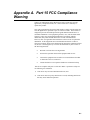
Appendix A. Part 15 FCC Compliance
Warning
Changes or modifications to the RF400 series radio systems not expressly
approved by Campbell Scientific, Inc. could void the user’s authority to
operate this product.
Note: This equipment has been tested and found to comply with the limits for a
Class B digital device, pursuant to part 15 of the FCC Rules. These limits are
designed to provide reasonable protection against harmful interference in a
residential installation. This equipment generates, uses, and can radiate radio
frequency energy and, if not installed and used in accordance with the
instructions, may cause harmful interference to radio communications.
However, there is no guarantee that interference will not occur in a particular
installation. If this equipment does cause harmful interference to radio or
television reception, which can be determined by turning the equipment off and
on, the user is encouraged to try to correct the interference by one or more of
the following measures:
•
Reorient or relocate the receiving antenna.
•
Increase the separation between the equipment and receiver.
•
Connect the equipment into an outlet on a circuit different from that
to which the receiver is connected.
•
Consult the dealer or an experienced radio/TV technician for help.
This device complies with part 15 of the FCC Rules. Operation is subject to
the following two conditions:
1) This device may not cause harmful interference, and
2) This device must accept any interference received, including interference
that may cause undesired operation.
A-1
This is a blank page.
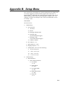
Appendix B. Setup Menu
Here is the structure of the RF400 series’ built-in Setup Menu system which can be
accessed by configuring a terminal emulator program such as ProcommTM or
HyperTerminalTM to 9600 baud (8-N-1) and pressing the “Program” button on the
RF400 with RF400’s RS-232 port cabled to appropriate COM port of PC. Also
displayed is a number representing the radio’s software and RF module versions.
For example: 6.425.
MAIN MENU
SW Version 6.425
1)
Standard Setup
a)
Active Interface
i)
Auto Sense
ii) RS-232
iii) Datalogger Modem Enable
iv) Datalogger SDC
(not for Table Based Loggers)
v) Datalogger CSDC
(only for Table Based Loggers)
vi) COM2xx to RF400
b) Net Address (0 – 63)
c)
Radio Address (0 – 1023)
d) Hopping Sequence ( 0 - 6)
e)
Standby Mode (select one of the following)
i)
<24 mA Always On
ii) < 4 mA 1/2 sec Cycle
iii) < 2 mA 1 sec Cycle
iv) < .4 mA 8 sec Cycle
2)
Advanced Setup
a)
Radio Parameters
i)
Radio Address Parameters
(1) Net Address
(0 – 63)
(2) Radio Address
(0 – 1023)
(3) Net Address Mask
(0 – 3fh)
(4) Radio Address Mask
(0 – 3ffh)
(5) Hop Table
(0 – 6)
B-1
Appendix B. Setup Menu
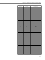
ii) Radio Standby Modes
(1) Standby Mode
(0 => 24 mA Always ON 3 => 4 mA 1/2 sec Cycle)
(4 => 2 mA 1 sec Cycle 5 => 1 mA 2 sec Cycle)
(6 => .6 mA 4 sec Cycle 7 =>.4 mA 8 sec Cycle)
(2) Time of Inactivity to Sleep
(units of 100 msec; 1 – 32767)
(3) Time of Inactivity to Long Header
(units of 100 msec; 0 – 65535)
Select 0 to always use long header
Select 65535 to never use long header
(4) Long Header Time
(units of 100 msec; 0 – 255)
iii) Radio AT Command Sequence Setup Menu
(1) AT Command Sequence Character
(any ASCII character)
(2) Silence time before Command Sequence
(units of 100 msec; 1 – 32767)
(3) Silence time after Command Sequence
(units of 100 msec; 1 – 32767)
(4) AT Command Mode Timeout
(units of 100 msec; 1 – 32767)
iv) Radio Diagnostics
Number of Retry Failures:
Received Signal Strength:
v) Radio Retry Settings
(1) Number of Retries
(0 – 255)
(2) Number of time slots for random retry
(units of 38 msec; 0 – 255)
(3) Number of bytes transmitted before delay
(1 – 65535)
(4) Sync Timer Setting;
(units of 100 msec; 0 – 255)
b) Interface Parameters
i)
CSDC Address (Not Active):
(7 or 8)
ii) RS-232 Auto Power Down Enable
0 => RS-232 always active to power RS-232 devices
1 => RS-232 TX automatically powers down when no activity for 30 sec
iii) RS-232 Parameters
(1) RS-232 Baud Rate:
0 => 1200
1 => 4800
2 => 9600
3 => 19.2k
B-2
Appendix B. Setup Menu
4 => 38.3k
(2) RS-232 Parity:
0 => None
1 => Odd
2 => Even
(3) RS-232 Character Length:
0 => 8 bits
1 => 7 bits
(4) RS-232 Stop Bits:
0 => 1
1 => 2
3)
Restore Defaults
4)
Show All Current and Default Settings
5)
Save All Parameters and Exit Setup
6)
Exit Setup without Saving Parameters
B-3
Appendix B. Setup Menu
This is a blank page.
B-4
Appendix C. RF400 Series Address and
Address Mask
Address
An RF400’s address is 16 bits:
(0 - 1111,1111,1111,1111)
(0 - ffffh)
0 – 65535)
binary
hexadecimal
decimal
The two parts of the address are the “Network Address” and the “Radio
Address.” The six most significant bits of the address are the “Network
Address”, and the ten least significant bits are the “Radio Address.”
Network Address
(0 - 11,1111)
(0 - 3fh)
(0 – 63)
Radio Address
(0 - 11,1111,1111)
(0 - 3ffh)
(0 – 1023)
binary
hexadecimal
decimal
Address mask
The RF400 has a user programmable 16-bit address mask. Like the address,
the address mask is divided into two parts. The six most significant bits are the
Network Address Mask and the remaining ten bits are the Radio Address
Mask.
When an incoming packet header’s address is compared with the RF400’s
address, only the address bits that correspond to address mask “1”s are used in
the comparison.
Example 1
Incoming Packet’s Header Address
RF400’s Network Address Mask
RF400’s Network Address
RF400’s Radio Address Mask
RF400’s Radio Address
xxxx xxxx xxxx xxxx
1111 11
yyyy yy
11 1111 1111
zz zzzz zzzz
Since the address mask is all “1”s, all of the incoming Packet Header Address
bits are compared against the corresponding RF400’s address bits.
Example 2
Incoming Packet’s Header Address
RF400’s Network Address Mask
RF400’s Network Address
RF400’s Radio Address Mask
RF400’s Radio Address
xxxx xxxx xxxx xxxx
1111 11
yyyy yy
11 1111 0000
zz zzzz zzzz
In this example, only the twelve most significant incoming Packet Header
Address bits are used in the comparison with the RF400’s twelve most
significant address bits because the entire address mask (Radio Address Mask
appended to Network Address Mask) is 1111,1111,1111,0000. Since the last
C-1
Appendix C. RF400 Series Address and Address Mask
four bits are not compared, any remote RF400 with Radio Address of 0 to 1111
(decimal 0 to 15) will be received by the base station.
This allows multiple remotes in a network to be received by the base without
changing the base Radio Address (the remotes cannot receive the base,
however).
Auto-Sense pre-configures as many settings as possible (including the address
mask). If you have an RF400 connected to a PC’s RS-232 port and a remote
RF400 connected to a datalogger’s CS I/O port, Auto-Sense will configure the
remote’s address mask to (3fh, 3ffh) so that it will only receive a 16-bit address
match (Network and Radio), but the base’s address mask to (3fh, 0h) so it will
receive any packet that has the same Network Address (and hopping sequence)
regardless of Radio Address.
Combined Network/ Radio Addresses
If programming PC208W for Point-to-Multipoint networks, the Generic Dial
Strings require the combined 16-bit addresses of the RF400s to be called. The
RF400 Setup Menu (in Standard Setup, Radio Address) calculates and displays
the combined network and radio address when you enter the network and radio
address values. Following are some examples.
C-2
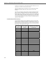
NET ADDRESS
(decimal)
RADIO ADDRESS
(decimal)
COMBINED 16-BIT ADDRESS
(hexadecimal)
0
0
0
0
0
0
0
0
0
0
0
0
0
0
0
0
0
0
0
0
0
0
0
0
0
0
0
0
0
0
1
2
3
4
5
6
7
8
9
10
11
12
13
14
15
16
17
18
19
20
21
22
23
24
25
26
27
28
0000
0001
0002
0003
0004
0005
0006
0007
0008
0009
000A
000B
000C
000D
000E
000F
0010
0011
0012
0013
0014
0015
0016
0017
0018
0019
000A
000B
000C
Appendix C. RF400 Series Address and Address Mask
NET ADDRESS
(decimal)
RADIO ADDRESS
(decimal)
COMBINED 16-BIT ADDRESS
(hexadecimal)
0
0
0
0
29
30
31
32
001D
001E
001F
0020
0
0
1022
1023
03FE
03FF
1
1
0
1
0400
0401
2
2
0
1
0800
0801
3
3
0
1
0C00
0C01
4
4
0
1
1000
1001
5
5
0
1
1400
1401
6
6
0
1
1800
1801
7
7
0
1
1C00
1C01
8
8
0
1
2000
2001
9
9
0
1
2400
2401
10
10
0
1
2800
2801
11
11
0
1
2C00
2C01
12
12
0
1
3000
3001
13
13
0
1
3400
3401
14
14
0
1
3800
3801
C-3
Appendix C. RF400 Series Address and Address Mask
C-4
NET ADDRESS
(decimal)
RADIO ADDRESS
(decimal)
COMBINED 16-BIT ADDRESS
(hexadecimal)
15
15
0
1
3C00
3C01
16
16
0
1
4000
4001
Appendix D. Advanced Setup Standby
Modes
The Standard Setup menu selections should fill the majority of user needs. The
following information is given in case you need to program a non-standard
standby mode.
The Standard Setup menu selections do not correspond with Advanced Setup
menu entries. For example: selecting a “3” in the Standard Setup menu selects
(< 2 mA 1 sec Cycle) whereas entering a “3” in the Advanced Setup menu
selects (< 4 mA 1/2 sec Cycle).
Table D-1. Advanced Setup Menu
STANDBY
MODE
STANDBY
AVG RECEIVE
CURRENT
Wake-up Interval
(red LED flash interval)
MAX.
RESPONSE
DELAY
01
< 24 mA
0 (constant)
0 sec
32
< 4 mA
½ sec
½ sec
3
< 2 mA
1 sec
1 sec
5
< 1 mA
2 sec
2 sec
6
< 0.6 mA
4 sec
4 sec
4
< 0.4 mA
8 sec
8 sec
1
2
4
7
Shaded modes 1, 2 not available
1
Standard Setup menu selection 1
Standard Setup menu selection 2
3
Standard Setup menu selection 3
4
Standard Setup menu selection 4
2
Standard Setup automatically configures the following three parameters
appropriately. If you configure a standby mode from the Advanced Setup
menu you must also manually configure these parameters according to the
following guidelines:
(1) Time of Inactivity to Sleep
(2) Time of Inactivity to Long Header
(3) Long Header Time
The first two parameters should be set to about the same value. What this
value is will depend upon the nature of the anticipated activity. The defaults
are 5 seconds and 4.8 seconds, so if you go more than 4.8 seconds without
activity, a long header is sent, and a corresponding 5 second receive delay will
be experienced.
D-1
Appendix D. Advanced Setup Standby Modes
In general, these inactivity timers should be set so that the RF400 stays on
(receiving or transmitting, not in standby mode) longer than the quiet times
during communication. You can experiment with this to see how it works.
TIME OF INACTIVITY TO SLEEP
The amount of receiver inactivity time desired before entering Standby Mode.
This number is only valid in receive and duty cycling modes. Valid numbers
range from 1 to 65535. The default number is 50 (for 5 seconds).
TIME OF INACTIVITY TO LONG HEADER
Set time before Long Header occurs. The time of inactivity on the wireless
modem’s receive pin before a long header is issued. The valid number range is
from 0 to 65535. 65535 selects no long header at all. The default is 48 (for 4.8
seconds).
LONG HEADER TIME
Sets long header duration in tenths of a second. The default is 7 (for 0.7
seconds). If changed from the default of 7, this number should be set to half of
the “Delay” indicated in the Standby Mode you are using + 200 ms. For
example, if your standby mode Delay is 4 seconds, set the Long Header Time
to 22 (tenths of a second) for 2.2 seconds. The valid number range is from 0 to
255. The longest long header time you should ever need is 8.2 seconds.
D-2
Appendix E. RF400 Series Port Pin
Descriptions
RS-232 Port
The “RS232” port is a partial implementation of RS-232C. It is configured as
Data Communications Equipment (DCE) for direct cable connection to Data
Terminal Equipment (DTE) such as an IBM-PC serial port.
RS-232 CONNECTOR, 9-PIN D-SUB FEMALE
PIN
1
2
3
4
5
6
7
8
9
I/O
DESCRIPTION
O
I
TX
RX
GND
O
CTS
I = Signal Into the RF400, 0 = Signal Out of the RF400
Only CTS is implemented for flow control. If data arrives (say from a PC)
faster than the RF400 transmits it, the RF400 will de-assert CTS when the 640
byte port buffer is full. If the PC continues to send data, the buffer will accept
it and may wrap around over-writing oldest data. PC208W and LoggerNet
monitor CTS to prevent buffer over-run.
The RF400 can transmit RF packets slightly in excess of 9600 baud. When RF
packets are received by the RF400, that data is immediately sent to the “active
interface” port without flow control (no RTS).
For many applications the RF400 works fine with no flow control. The need
for flow control arises when longer standby modes are used, where more data
could be sent than the 640 byte buffer can hold before transmittal. For
example, if the RF400s are in Standby Mode 6 (see Appendix D), an RF400
needs to buffer incoming RS-232 data for up to 8 seconds while waiting for
the other RF400 to wake up before transmitting it. Also, if the RF400 is doing
a lot of retries, that can take extra time and require flow control to avoid buffer
over-run.
CS I/O Port
The CS I/O port is Campbell Scientific's input/output port. It is not a standard
RS-232 pin-out. The following table provides pin-out information on the port
when connected to a datalogger.
E-1
Appendix E. RF400 Series Port Pin Descriptions
CS I/O CONNECTOR, 9-PIN D-SUB MALE
PIN
FUNCTION
I/O
DESCRIPTION
1
2
3
5V
GND
Ring
I
O
4
5
RX
Modem Enable
O
I
6
Synchronous Device
Enable
I
7
CLK/Handshake
I/O
8
12V supplied by
datalogger
TX
PWR
Sources 5 VDC to power peripherals
GND for pin 1 and signals
Raised by modem to put datalogger
into telecommunications mode
Serial data receive line
Raised when datalogger determines
that associated modem raised the
ring line
Used by datalogger to address
synchronous devices; can be used as
a printer enable
Used by datalogger with SDE and
TX lines to transfer data to
synchronous devices
Sources 12 VDC to power
peripherals
Serial data transmit line
9
I
I = Signal Into the RF400, 0 = Signal Out of the RF400
E-2
Appendix F. Datalogger RS-232 Port to
RF400 Series Radio
A connection from RF400 RS-232 port to CR23X or CR5000 RS-232 port
requires a 9-pin male to 9-pin male null-modem cable. This cable is available
as CSI Item # 14392.
A 12-Volt Field Power Cable (Item # 14291) or AC adapter (Item # 15966)
must be installed to furnish 12 V to the “DC Pwr” connector on the RF400.
The RF400 can operate with Active Interface in either the Auto Sense mode
(default) or in the RS-232 mode with this configuration.
With the CR23X, the *D 12 “--” setting (to turn datalogger RS-232 port on) is
not required.
F-1
This is a blank page.
Appendix G. Short-Haul Modems
Set SRM-5A at PC end to “DCE” mode.
Set SRM-5A at RF400 end to “DTE” mode.
The PC to SRM-5A cable is typically a 9-pin female to 25-pin male (CSI Item
# 7026). The SRM-5A to RF400 cable is 25-pin male to 9-pin male available
as CSI Item # 14413.
LoggerNet or PC208W Network Map:
COM1
CR10X1
AC Adapter
apx
TECHNOLOGIES INC.
HICKSVILLE, NEW YORK
CLASS 2 TRANSFORMER
MODEL NO: INPUT:
OUTPUT:
UL
R
AP2105W
120VAC 60Hz 20W
12VDC 1.0A
LISTED
2H56
E144634
UL
R
MADE IN CHINA
SRM-5A Short-haul Modems
RS-232
DC
Pwr
-
+
XMT
+ G
DCE
RCV
-
-
+
XMT
RF400
Spread Spectrum Radio
CS I/O
DTE
+ G
RCV
-
DTE
DCE
Logan, Utah
RS232
This device contains transmitter module:
FCC ID: OUR-9XTREAM
The enclosed device complies with Part 15 of the
FCC Rules.
Program
Operation is subject to the following two conditions:
(1) This device may not cause harmful interference,
and (2) this device must accept any intererence
Pwr/TX
received, including interference that may cause
Antenna
RX
undesired operation.
Serial #
DCE
14320
MADE IN USA
DTE
Datalogger CS I/O
CS I/O
G 12V
Logan, Utah
SW 12V CTRL
SE
DIFF
7
8
9
L
AG H
G
H
10
5
4
G
L
11 12
6
L AG E3
AG H
SW 12V
AG G
G
5V 5V G
DC
Pwr
Logan, Utah
G 12V
POWER
IN
CS I/O
G
CR10X WIRING PANEL
MADE IN USA
RS232
RF400
Spread Spectrum Radio
CS I/O
This device contains transmitter module:
FCC ID: OUR-9XTREAM
SE
DIFF
1
2
3
L
AG H
G
H
4
5
L
AG H
2
1
G
The enclosed device complies with Part 15 of the
6
SDM
3
L
AG E1
AG E2 G
P1 G
P2 G C8 C7 C6 C5 C4 C3 C2 C1 G 12V 12V
FCC Rules.
Program
EARTH
GROUND
Operation is subject to the following two conditions:
(1) This device may not cause harmful interference,
and (2) this device must accept any intererence
Pwr/TX
received, including interference that may cause
Antenna
RX
undesired operation.
Serial #
14320
WIRING
PANEL NO.
MADE IN USA
FIGURE G-1. Short-Haul Modem to RF400 Setup
Configure RF400s for point-to-point (see Software Setup Section 5.3). Default
settings should work unless there is a neighboring network (see Section 5.3.1,
4.d).
12 V power for the base RF400 can be supplied by an AC adapter as shown or
a Field Power Cable (see Power Supplies in Section 4.4). Current dataloggers
will supply remote RF400 power via serial cable.
G-1
Appendix G. Short-Haul Modems
NOTE
With short-haul modems it is necessary to configure the base
station RF400’s “RS-232 Auto Power Down Enable” (in the
Advanced Setup \ Interface Parameters menu) to mode "0" which
will maintain the radio's RS-232 port always active. This results
in an additional constant 2 mA current drain by the RF400. If
you don’t do this, the base RF400’s RS-232 port will turn off 30
seconds after activity and the attached SRM-5A which gets its
power from the port will not receive any messages from the PC.
This is a blank page.
G-2
Appendix H. Distance vs. Antenna
Gain, Terrain, and Other Factors
RF Path Examples
Distance
Achieved
(miles)
2
10
35
Antennas
14204 OMNI ½ Wave 0 dBd* Whip
to
14204 OMNI ½ Wave 0 dBd Whip
14204 OMNI ½ Wave 0 dBd Whip
to
14204 OMNI ½ Wave 0 dBd Whip
14204 OMNI ½ Wave 0 dBd Whip
to
14201 9 dBd YAGI
Path Between Radios
Virtual line-of-sight on valley floor with
wetland foliage.
Line-of-sight across a valley (on foothills
approximately 300 feet above the valley
floor on each end).
Line-of-sight across a valley (on foothills
approximately 300 feet above the valley
floor on each end).
* dBd = decibel level compared to a simple dipole antenna
LINE-OF-SIGHT
You should arrange for a line-of-sight signal path between RF400s. At 900
MHz or 2.4 GHz there is little signal bending, however, there is reflection from
hills, water, and conductive objects. Sometimes reflections provide a helpful
path around an obstacle. There can be some trees and bushes in the signal path
(with reduction in signal strength), but a hill will block the signal effectively.
Thick trees can limit range to as little as 800 feet. Where possible avoid
buildings and other man-made structures in the signal path as they absorb or
reflect some of the direct wave, possibly below the level needed for
communications.
ANTENNA HEIGHT
In situations where the RF400 antennas are situated virtually line-of-sight, the
elevation of antennas (by choice of site or by installing a tower or mast) can
substantially increase signal strengths. The amount of increase depends on
factors in the propagation path between the radios including terrain, foliage,
and man-made structures. Elevating one or both of the antennas essentially
raises the signal path allowing the direct wave to better avoid absorption or
reflection which can sometimes be more helpful than adding higher gain
antennas.
GAIN ANTENNAS
Increasing antenna gains improves signal strength and distance. For example,
the substitution of a 9 dBd yagi antenna where a 0 dBd OMNI existed
theoretically extends the attainable distance by a factor of 2.8. Adding 9 dBd
yagi antennas on both ends in place of 0 dBd OMNIs theoretically extends the
distance by a factor of 7.9. The higher the yagi’s gain, the narrower the beam
width and the more critical it is that it be aimed right on target.
H-1
Appendix H. Distance vs. Antenna Gain, Terrain, and Other Factors
How Far Can You Go?
Distance Estimates for Spread Spectrum Radios
Overview
There is a great deal of interest in estimating the distance you can expect to
achieve with the RF400 radios. Also of interest are the effects of cable length,
antenna gain, and terrain. Some of these items are easy to quantify (cable loss,
for instance); others are difficult to quantify (such as the effect of ground
reflections). They are all important, though, and affect how well the RF system
performs.
Probably the best approach to take in making range estimates is to do a site
survey that considers the topography, location of antennas and radios, and
cable lengths, make some assumptions about the path losses, and see if there is
still some net gain. If there is, or if it is close, the next course is to actually try
it out.
Link Analysis
In an RF system, there are gains (transmitter power, antenna gains, and
receiver sensitivity “gain”) and losses (cable loss and path loss). If the gains
exceed the losses, you have a connection; any excess is the “link margin”.
Parenthetical values pertain to 2.4 GHZ
EXAMPLE GAINS
EXAMPLE LOSSES
Transmitter Power
Transmitter Antenna
Receiver Antenna
Receiver Sensitivity “gain”
20 (17)
6
6
110 (104)
TOTAL GAINS
142 (133) dB TOTAL LOSSES
=
Transmitter Cable
Free Space
Receiver Cable
3
120
3
=
126 dB
Link Margin = (Total Gains) – (Total Losses) = 142 (133) – 126 = 16 (7) dB
A minimum of 6 dB of link margin is recommended.
Here is a block diagram of the various components of gain/loss:
Radio
Transmitter
Pt
Cable
Loss
-
Lt
Antenna
Gain
+
Gt
Free Space
Loss
-
Lp
Antenna
Gain
+
Gr
Cable
Loss
-
Lr
Radio
Receiver
=
Pr
Where:
Pt =>
transmitter output power, in dBm (20 dBm in the case of the RF400
or RF410)
Lt =>
cable loss between transmitter and antenna in dB (see Cable Loss section)
Gt => transmit antenna gain in dBi (dBi = dBd + 2.15)
Lp => path loss between isotropic antennas in dB (see Tables H-1, H-2)
Gr => receive antenna gain in dBi
Lr =>
cable loss between antenna and receiver in dB
H-2
Appendix H. Distance vs. Antenna Gain, Terrain, and Other Factors
Pr =>
signal power at the radio receiver in dBm
The signal power at the receiver (Pr) must exceed the receiver sensitivity
(−110 or –104 dBm) by a minimum of 6 dB for an effective link. The amount
that Pr exceeds –110 dBm or –104 dBm (2.4 GHz) is the link margin.
All of these elements are known, or are easily determined, with the exception
of Lp. Unfortunately, signal path loss can make the difference between a
marginal link ½ mile apart, and a reliable link 10 miles apart!
Transmitter Power
Transmitter output power is often expressed in dBm, which is a decibel power
rating relative to 1 milliWatt. The formula is: dBm = 10 log (Pt) with Pt
expressed in milliWatts.
Transmitter Power (Pt)
(milliWatts)
1
10
50 (RF415)
100 (RF400 or RF410)
1000
5000
dBm
0
10
17
20
30
37
Cable Loss
Cable loss is a function of cable type, length, and frequency and is usually
specified as attenuation (dB) per 100’ of cable. Using a low loss cable
becomes very important as the cable run distances increase. Here are some
typical cable types and their properties:
Cable Type
Outside Diameter
RG-58A/U
.195”
COAX RPSMA-L
.195”
RG-8
.405”
COAX NTN-L
.405”
LMR-400
.405”
*CSI stocked antenna cables are shaded.
Loss (dB/100’) @ 900 MHz
21.1
11.1
6.9
4.5
3.9
Loss (dB/100’) @ 2.4 GHz
18.8
8.1
6.7
CSI’s “COAX RPSMA-L” uses LMR-195 antenna cable. Cable loss is
proportional to length as the following table illustrates.
LMR-195 Cable Loss vs. Length @ 900 MHz
LENGTH
(ft.)
100
50
25
10
6
LOSS
(dB)
11.1
5.6
2.8
1.1
0.7
H-3
Appendix H. Distance vs. Antenna Gain, Terrain, and Other Factors
Antenna Gain
Antenna gain is specified either in dBi (decibels of gain relative to an isotropic
radiator) or in dBd (decibels of gain relative to a dipole). The relationship is:
dBi = dBd + 2.15
Some antennas that are FCC approved for use with the RF400 series are:
Mfg.
Antenna Type
Band
Model
CSI Item #
Astron
Antenex
MaxRad
LINX
MaxRad
Omni (1/2 wave)
Collinear
Yagi
Omni (1/2 wave)
Enclosed Yagi
900 MHz
900 MHz
900 MHz
2.4 GHz
2.4 GHz
AXH900 RP SMA R
FG9023
BMOY8905
ANT-2.4-CW-RCT-RP
WISP24015PTNF
14204
14221
14201
16005
16755
dBd
Gain
0
3
9
0
13
dBi
Gain
2.15
5.15
11.15
2.15
15.1
Size
6.75”
24”
21.4”
4.5”
17”
Receiver Sensitivity
Receiver sensitivity is usually specified in dBm for a specific bit error rate
(BER). The transceiver module used in the RF400 (either 900 MHz radio) is
-4
specified at –110 dBm at ~10 raw BER.
If the received signal strength is greater than the receiver sensitivity, a link can
be established. Any excess signal strength above the receiver sensitivity is
“link margin”, and is a very good thing; a minimum of 6 dB of link margin
should be sought.
Path Loss
We have combined in this section the normal “free space” path loss (only seen
in mountaintop to mountaintop scenarios) with loss due to ground reflections,
diffraction, leaf/forest absorption, etc. It is all loss!
A starting point is the “free space” path loss. Here are two equations for this:
Lp (dB) = 32.4 + 20 x log( f ) + 20 x log ( d ) dB
Lp (dB) = 36.6 + 20 x log( f ) + 20 x log ( d ) dB
(f in MHz, d in km)
(f in MHz, d in miles)
Here is a table showing the free space path loss (in dB). Note the effect of
frequency.
Frequency
400 MHz
915 MHz
2.4 GHz
1 mi.
89
96
104
2 mi.
95
102
110
4 mi.
101
108
116
8 mi.
107
114
122
Distance
10 mi.
16 mi.
109
113
116
120
124
128
22 mi.
115
123
131
26 mi.
117
124
133
30 mi.
118
125
134
Notice the relationship between path loss and distance: each time you double
the distance, you lose 6 dB of signal under free space conditions. Or, put
another way, if you add 6 dB of gain (for example with 6 dB of additional
antenna gain, or 6 dB less cable loss), you can double the distance for free
space conditions.
H-4
Appendix H. Distance vs. Antenna Gain, Terrain, and Other Factors
As mentioned before, free space conditions are the ideal, but seldom actually
seen. The higher the antenna height relative to the terrain in the line of sight
path, the closer to free space conditions. Antenna height is everything!
Here are some additional propagation effects that increase the path losses:
Diffraction
This is caused by objects close to the line of sight path. Real world examples
of this would be hills, buildings, or trees. The object may not be in the direct
line-of-sight, but if it is close enough, it will cause the RF to diffract around the
object, giving additional path loss. “Close enough” is a function of frequency,
path length, and position of the obstacle along the path.
An example at 900 MHz: a 10 mile path length with an obstacle halfway along
the path will see diffraction “losses” from an obstacle within ~70 ft. of line-of
sight. The amount of loss would be from 6 dB to 20 dB, depending on the
obstacle surface. A sharp edge (like a rock cliff) would give the minimum loss
(6 dB), while a rounded hill would give the maximum loss (20 dB).
Ground Reflections
These are caused by the RF signal being reflected from the ground (or water),
and undergoing a phase shift so that it destructively interferes with the line of
sight signal. The conditions that cause this the most are propagation over
water, or over a low-lying fogbank. The reflected signal suffers little
attenuation, gets out of phase, and interferes with the main signal. If antennas
need to be sited near water, they should be positioned away from the water’s
edge so that the ground vegetation attenuates the reflected RF.
The result of the reflection and interference (worst case) is that the path loss
increases as the 4th power of the distance, instead of the 2nd power. This
changes the distance term in the path loss equation to: 40 x log ( d ) dB.
Then, with each doubling of distance, the path loss increases by 12 dB, instead
of 6 dB.
Vegetation
Losses due to vegetation (trees, bushes, etc) cause the path loss to increase by
the 3rd to 4th power of the distance, instead of the 2nd power. This is just like in
the severe ground reflection case above.
Rain, Snow, and Fog
Below 10 GHz, these don’t have much effect on path loss (see Ground
Reflections).
Real World Distance Estimates
From the above discussion of departures from the ideal “free space” path loss,
it is clear that we should usually use something other than the 2nd power
distance table.
H-5
Appendix H. Distance vs. Antenna Gain, Terrain, and Other Factors
Here is a table which gives calculated path loss (Lp) values at 900 MHz for the
2nd, 3rd, and 4th powers of distance; the equations (for 915 MHz) are:
Lp (2nd power) = 95.8 + 20 × log ( d ) dB
Lp (3rd power) = 95.8 + 30 × log ( d ) dB
Lp (4th power) = 95.8 + 40 × log ( d ) dB
(d in miles)
(d in miles)
(d in miles)
Example calculated Lp values (in dB)
TABLE H-1. 900 MHz Distance vs. Path Loss (Lp in dB) per Three Path Types
Path Type
2nd power
3rd power
4th power
2 mi.
102
105
108
4 mi.
108
114
120
6 mi.
111
119
127
8 mi.
114
123
132
10 mi.
116
126
136
14 mi.
119
130
142
18 mi.
121
133
146
22 mi.
123
136
149
26 mi.
124
138
152
30 mi.
125
140
155
The following table helps select a Path Type in the above “Distance vs. Path
Loss” table to best fit your situation.
TABLE H-2. Path Type vs. Path
Characteristics Selector
Path Type
2nd power
3rd power
4th power
Path Characteristics
Mountaintop to mountaintop
or Tall antenna towers
Line-of-sight
Dominantly line-of-sight
Low antenna heights
Some trees
At water’s edge (very reflective)
Across field of grain (reflective)
Lots of Trees (absorptive)
Examples
Some examples will help illustrate the tradeoffs in a link analysis. These
examples will all use the RF400 900 MHz radio, and will use –107 dBm as the
required power level at the radio receiver. This is 3 dB higher than the quoted
sensitivity of –110 dBm, which will give us a 3 dB margin.
Here’s the equation we will use, from the first page:
Pt - Lt + Gt - Lp + Gr - Lr = Pr
Example #1
Antenex FG9023 antennas on each end, 20’ of LMR195 cable on one end, 10’
of LMR195 on the other end, antennas at 10’ height, fairly open terrain with a
few trees. How far can I go?
Pt = 20 dBm
Lt = 20’ x (11.1 dB/100 ft) = 2.22 dB
Gt = Gr = 3 dBd = 5.15 dBi
Lr = 10’ x (11.1 dB/100 ft) = 1.11 dB
H-6
Appendix H. Distance vs. Antenna Gain, Terrain, and Other Factors
Use –107 dBm for Pr, solve for Lp: Lp = 135 dB
Use the 3rd to 4th power tables: Range from ~9 (4th power) to ~22 (3rd power)
miles
Example #2
Base has MaxRad BMOY8905 Yagi, with 50’ of LMR195 cable on a 30’
tower, also a lightening protection device with a VSWR of 1:1.75; remote also
has a MaxRad BMOY8905 Yagi with 5’ of LMR195 cable on a 4’ pole.
Terrain is mostly flat, with sagebrush. How far can I go?
Pt = 20 dBm
Lt = 50’ x (11.1 dB/100 ft) = 5.55 dB
Gt = 9 dBd = 11.15 dBi
Lr = 5’ x (11.1 dB/100 ft) = .55 dB
Gr = 9 dBd = 11.15 dBi
Need to include the loss from the surge arrestor: VSWR of 1:1.75 = .34 dB loss
Use –107 dBm for Pr, solve for Lp: Lp = 143 dB
Use the 3rd to 4th power tables: Range from ~14 (4th power) to 30+ (3rd power)
miles
Example #3
You need to run 125’ of cable for the transmitter:
How much loss if I use LMR195 cable?
125’ x (11.1 dB/100’) = 13.9 dB
How much loss if I use LMR400 cable?
125’ x (3.9 dB/100’) = 4.9 dB
If I am using path loss from the 2nd power table, and operating fine at 8 miles
with LMR195 cable, how much more range could I expect if I use LMR400
cable (assuming similar terrain)?
13.9 dB – 4.9 dB => 9 dB more link margin
Loss at 8 miles: 114 dB; could tolerate 114 + 9 dB = 123 dB loss =>>> 22
miles (14 miles more)
H-7
Appendix H. Distance vs. Antenna Gain, Terrain, and Other Factors
This is a blank page.
H-8
Appendix I. Phone to RF400 Series
Where a phone to RF400 Base is desired, the following configurations will
provide Point-to-Point or Point-to-Multipoint communications. To have a base
datalogger in this configuration requires that another RF400 be added at the
base.
1.
HARDWARE REQUIREMENTS
a.
b.
c.
d.
e.
2.
RF400s
COM210
PS512M (or CH512R and battery)
(have built-in null-modems and supply power for RF400 and
COM210)
AC charger (CSI Item # 9591) or solar panel
Two SC12 cables (one included with RF400 and one with COM210)
POINT-TO-POINT COMMUNICATIONS
PC-Modem ------------ COM210-PS512M-RF400------------ RF400-DL
(null-modem)
LoggerNet SETUP
a.
Setup:
ComPort_1
PhoneBase
PhoneRemote
RF400
RF400Remote
CR10X
b.
ComPort_1 – default settings
c.
PhoneBase
1) Maximum Baud Rate – 9600
2). Modem Pick List – per PC’s phone modem
3) Extra Response Time – 0 s
d.
PhoneRemote – input base site’s phone number
e.
RF400 – make Attention Character: “-“ ; leave the rest defaults
f.
RF400Remote – Radio Address: “0” ; leave the rest defaults
g.
CR10X – default settings, schedule collections as desired
PC208W SETUP
a.
Device Map
COM1
Modem1
CR10X1
b.
COM port - Default settings
I-1
Appendix I. Phone to RF400 Series
c.
Phone Modem
1) Baud Rate – 9600
2) Modem Pick List – per PC’s phone modem
3) Extra Response Time – 2000 ms
d.
Datalogger – Dialed Using Phone # at Base site
RF400 CONFIGURATION
a.
Base RF400
1) Active Interface: “COM2xx to RF400”
2) AT Command (Attention) Character: “-“
3) All other settings: defaults
b.
Remote RF400 – leave all settings: defaults
Note: If there is a neighboring RF400 network, you should change
the Hopping Sequence of base and remote RF400s to a new setting to
avoid interference (see Section 5.3.1 for method to detect neighboring
network).
3.
POINT-TO-MULTIPOINT COMMUNICATIONS
PC-Modem ------------ COM210-PS512M-RF400 ------------ RF400-DL1
(null-modem)
------------ RF400-DL2
LoggerNet SETUP
a.
Setup:
ComPort_1
PhoneBase
PhoneRemote
RF400
RF400Remote
CR10X
RF400Remote_2
CR10X_2
b.
ComPort_1 – default settings
c.
PhoneBase
1) Maximum Baud Rate – 9600
2) Modem Pick List – per PC’s phone modem
3) Extra Response Time – 0 s
I-2
d.
PhoneRemote – input base site’s phone number
e.
RF400 – make Attention Character: “-“ ; leave the rest defaults
f.
RF400Remote – make Radio Address: “1“ ; leave the rest defaults
g.
RF400Remote_2 – make Radio Address: “2“ ; leave the rest defaults
h.
Dataloggers – default settings, schedule collections as desired
Appendix I. Phone to RF400 Series
PC208W SETUP
a.
Network Map
COM1
Modem1
Generic1
CR10X_1
CR10X_2
b.
COM port - default settings
c.
Phone Modem
1) Baud Rate – 9600
2) Modem Pick List – per PC’s phone modem
3) Extra Response Time – 2000 ms
d.
Generic Modem
1) Dialed Using phone # at base site
2) √ Make DTR Active and √ Hardware Flow Control
e.
Datalogger 1
1) Dialed Using Generic Modem Dial String:
D1000T"---"R"OK"9200T"ATDT0001^m"R"OK"1200T"ATCN
^m"R"OK"1200
2) Set up scheduled collections as desired.
f.
Datalogger 2
1) Dialed Using Generic Modem Dial String:
D1000T"---"R"OK"9200T"ATDT0002^m"R"OK"1200T"ATCN
^m"R"OK"1200
2) Set up scheduled collections as desired.
“0001” in the first ATDT command is the hexadecimal representation of
the combined Network Address / Radio Address chosen for this example
(i.e., Network Address = 0, Radio address = 1). The RF400 Setup Menu
calculates and displays this number for you in Standard Setup as “0001h”.
RF400 CONFIGURATION
a.
Base RF400
1) Active Interface: “COM2xx to RF400”
2) AT Command Character: “-”
3) All other settings: defaults
b.
Remote RF400s
1) Radio Addresses: 1, 2, etc. (unique for each remote RF400 and
must agree with respective RF400Remote settings)
2) All other settings: default
Note 1: Using a non “+” Command Character for the base RF400 is
necessary so the phone modem in the path passes the AT commands
on to the base RF400 rather than responding to them.
Note 2: If there is a neighboring RF400 network, you should change
the Hopping Sequence of base and remote RF400s to a new setting to
avoid interference (see Section 5.3.1 for method to detect neighboring
network).
I-3
Appendix I. Phone to RF400 Series
FIGURE I-1. LoggerNet Point-to-Multipoint Setup
4.
HARDWARE
After configuring LoggerNet or PC208W and the RF400s you are ready to
set up hardware. The PS512M null-modem connectors (it’s not important
which connector goes to which unit) connect via SC12 cables to the
COM210 and the base RF400 CS I/O port. Connect the site phone line to
COM210. Connect power to PS512M. Connect antenna to RF400.
When you turn on the PS512M supply, the RF400 receives 12V power
and you will see the LEDs light in their power-up sequence.
Remote RF400s normally connect to datalogger CS I/O ports via SC12
cables. Powering up the datalogger will start the RF400 operating. Install
an antenna (or antenna cable and yagi or collinear) and you are ready to
collect data.
I-4
Appendix J. Monitor CSAT3 via RF400
Series
Procedure for installing a pair of RF400 series spread spectrum radios for
monitoring a CSAT3 system at a distance. This function has traditionally been
implemented by running a short haul modem cable between CSAT3 and PC.
HARDWARE REQUIREMENTS
•
•
•
•
•
•
•
Two RF400s (mounting bracket option available)
Two RF400 antennas (and possibly cables, see Section 4.4 for
options)
Base Cable/Power Kit Item #14220 (contains 120V AC Adapter and
6 ft. PC to RF400 serial cable).
Remote station 12V Field Power Cable Item # 14291 or (if 120VAC
is available), AC adapter Item # 15966
9 pin male to 9 pin male null-modem serial cable (CSI Item # 14392)
PC with HyperTerminalTM or ProcommTM for RF400 setup (if
neighboring RF400s).
Spare PC COM port (COMx)
RF400 SETUP
(1) Plug AC adapter into 120VAC outlet; plug barrel connector into
“base” RF400 and wait 10 seconds for RF400 to initialize.
(2) Connect 6 ft. cable (from base kit) between PC COM port and base
RF400 RS-232 port.
(3) Run HyperterminalTM or ProcommTM on PC and configure for
(a)
(b)
(c)
(d)
(e)
Baud rate: 9600, 8-N-1
Flow control: none
Emulation: TTY
ASCII
COMx (direct connect)
Note: if using HyperterminalTM it will probably be necessary to do a
Call Disconnect and then a Call Connect for new settings to take
effect.
(4) Press “Program” button on RF400
The following text should be written to the terminal screen
Main Menu
SW Version XX.YYY
(1) Standard Setup
(2) Advanced Setup
(3) Restore Defaults
(4) Show All Current & Default Settings
(5) Save All Parameters & Exit Setup
(9) Exit Setup without Saving Parameters
Enter Choice:
J-1
Appendix J. Monitor CSAT3 via RF400 Series
(5) Select “1” for “Standard Setup” and configure the following
(a) Active Interface – leave at default “Auto Sense”
(b) Network Address – can be default “0” if no neighboring RF400
networks are operating; otherwise choose a different network
address (see RX LED Test below).
(c) Radio Address – can be default “0”
(d) Hopping Sequence – can be default “0” if no neighboring RF400
networks are operating; otherwise choose a different hopping
sequence (1 – 6).
- RX LED Test To determine if there is a neighboring RF400 network in
operation using the same hopping sequence as yours, stop
communications on your network and observe RF400 green
LEDs for activity. At this point, any green LED activity would
indicate that there is a nearby network using the same hopping
sequence.
The other network’s network and/or radio addresses might be
different than yours, so having the same hopping sequence isn’t
necessarily a serious problem but having an exclusive hopping
sequence results in fewer retries.
(e) Standby Mode – leave at default “2”
(f) Retry Level – if RF noise is a problem, try “Low” or a higher
level to see if response improves.
(6) Repeat steps 1 - 5 with “remote” RF400. Temporarily use 6 ft. cable
and AC adapter during the remote RF400 setup. CSAT3 monitoring
requires a Point-to-Point network so you should configure all remote
RF400 settings the same as you did for the base RF400.
CSAT3 SETUP
(1)
(2)
(3)
(4)
(5)
(6)
(7)
(8)
Power CSAT3 off and then back on
Connect CSAT3’s RS-232 cable to the desired PC COM port
Run CSAT32 software
Select correct COM port if necessary under Settings\Communication
Enter Terminal mode (bottom tab)
Open Port (if not already open)
Press [Enter] a couple of times to get “>“ prompt
Enter “br 0” and press [Enter] to send it to CSAT3 to configure RS232 communications to 9600 baud (the RF400 always communicates
at 9600 baud).
(9) Enter “ri 1” and press [Enter] to send it to CSAT3 to turn on RS-232
drivers (if you want to save this setting in non-volatile RAM, refer to
CSAT3 Instruction Manual, Appendix B).
(10) Return to Data mode (bottom tab)
HARDWARE SETUP
(1) Base station
(a) Plug AC adapter into 120 VAC outlet and barrel connector into
“DC Pwr” jack on base RF400.
(b) Connect 6 ft. cable (from base kit) between PC COM port of
choice and RF400 RS-232 port.
J-2
Appendix J. Monitor CSAT3 via RF400 Series
(2) Remote station
(a) Connect 12 V power supply to RF400 (can be either 120V AC
adapter or 12V Field Power Cable)
(b) Connect 9 pin male to 9 pin male null-modem cable from
CSAT3 RS-232 connector to RF400’s RS-232 connector.
(c) You are ready to start taking measurements
TROUBLESHOOTING
(1) If your readings appear off-scale, try closing CSAT32 and running it
again.
(2) If not communicating with anemometer, make sure RS-232 driver is
turned on (see CSAT3 SETUP).
J-3
Appendix J. Monitor CSAT3 via RF400 Series
This is a blank page.
J-2
Appendix K. RF400/RF410 Pass/Fail
Tests
This appendix describes a method to functionally test RF400/RF410 system
components including:
•
PC COM port
•
SC12 serial cable
•
RF400/RF410
•
RF400/RF410 Antenna
Hardware/Software Required
9
PC with one available COM port
9
Terminal Program (HyperTerminalTM or ProcommTM)
9
Two RF400/RF410s
9
Two SC12 serial cables
9
¼ wave OMNI antenna (CSI Item # 14310)
9
Two power supplies rated 12 Volts, 1 Amp
(recommend AC adapter Item # 15966 and any 12 V battery pack with
Field Power Cable Item # 14291)
The following descriptions tell how to build an RF400/RF410 loop-back test
system. Recommendations are given as to where to place the system to avoid
rf-reflections (see TESTING ¼ Wave Antenna footnote 2 in this appendix).
The basic parts of the system are:
1)
PC running a terminal program and a serial cable from PC COM port to
base RF400/RF410
2)
Base RF400/RF410
3)
Remote RF400/RF410 with RS-232 port jumper wire between TX (pin 2)
and RX (pin 3) for data loop-back.
Build the RF400/RF410 test system in the order shown:
1)
TESTING SC12 CABLE and PC COM PORT
2)
TESTING RF400/RF410s
3)
TESTING ANTENNAS
Label components of the system “known-good” as they pass the test.
TESTING SC12 CABLE and PC COM PORT
(1) Run a terminal program such as HyperTerminalTM or ProcommTM
(a) Baud rate: 9600
(b) Data, Parity, Stop Bits: 8-N-1
(c) Flow control: none
K-1
Appendix K. RF400/RF410 Pass/Fail Tests
(d) Emulation: TTY
(e) ASCII
(f) COM1 (or any available COM port)
NOTE
With some versions of HyperTerminalTM after changing a setting
it is necessary to do a “Call Disconnect” (or “Disconnect”)
followed by a “Call Connect” (or “Call”) for the new setting to
register.
(2) Connect an SC12 to the selected PC COM port either directly or via
known-good RS-232 cable.
(3) Temporarily short together pins 2 and 3 (RX and TX) of the SC12 cable’s
male connector using a small (22 - 24 gage) copper wire, PC card jumper,
or flat-bladed screwdriver. Take care to connect only pins 2 and 3.
End view of male SC12 Connector
(4) Press any alpha-numeric keys on PC keyboard.
NOTE
Make sure that Properties/Settings/ASCII Setup “Echo characters
locally” or the equivalent ProcommTM setting is NOT enabled.
(5) If the SC12 cable is good you will see characters “echo” to the screen as
you press the keys.
(6) Remove the short circuit from the SC12 connector. Key presses should
now cease to echo back.
(7) Test the SC12 cable’s female drop by gently inserting a u-shaped portion
of paper-clip into pins 2 and 3 and repeating steps 4 to 6 inclusive.
End view of female SC12 Connector
CAUTION
K-2
Be sure to remove shorts between pins 2 and 3 when
done.
Appendix K. RF400/RF410 Pass/Fail Tests
TESTING RF400/RF410s
After verifying the functionality of the terminal program and the integrity of
the serial cable and COM port, proceed as follows:
(1) Connect 12V power to an RF400/RF410. This can be from an AC adapter
(Item # 14220 or Field Power Cable (Item # 14291) with 12V battery pack
attached (see step 12 below).
(2) Connect first RF400/RF410’s RS-232 port to the PC COM port
(3) Run a terminal program such as HyperTerminalTM or ProcommTM
(a) Baud rate: 9600
(b) Data, Parity, Stop Bits: 8-N-1
(c) Flow control: none
(d) Emulation: TTY
(e) ASCII
(f) Desired COM port
NOTE
Make sure that Properties/Settings/ASCII Setup “Echo characters
locally” or the equivalent ProcommTM setting is NOT enabled.
(4) Press “Program” button on RF400/RF410
(5) Select “3” to restore defaults, then select “5” to save parameters and exit
NOTE
The presence of a neighboring RF400/RF410 network with
default settings could interfere with your tests (see Section 5.3.1.
(4.d) for detection method).
(6) Repeat steps 1 to 5 inclusive with second RF400/RF410
(7) Label the RF400/RF410 connected to the PC COM port as “Base”
(8) Place the two RF400/RF410s side by side with antenna connectors 1 1/8
inches apart on a non-metallic surface (see Figure K-1).
FIGURE K-1. Loop-back Test without Antennas
K-3
Appendix K. RF400/RF410 Pass/Fail Tests
(9) Make sure that no antennas are attached to the RF400/RF410s
(10) Label the other RF400/RF410, “Remote”
(11) Insert jumper into the Remote RF400/RF410’s RS-232 connector pins 2
and 3 (using a U-shaped portion of a paper clip) allowing data received
from base RF400/RF410 to be transmitted back to terminal screen by
remote RF400/RF410.
RF400/RF410’s RS-232 Connector (female)
(12) Connect 12V power to Remote RF400/RF410. This can be supplied by an
AC adapter (Item # 14220) or Field Power Cable (Item # 14291)
connected to a 12V battery (battery can be an 8 cell pack of alkaline A, C,
or D cells, or a lead-acid battery).
NOTE
If your 12V power supply is a battery pack or rechargeable
battery, make sure that the batteries are fresh or well-charged so
they can supply the 75 mA peak current needed when the
RF400/RF410 is transmitting in order to obtain valid test results.
CAUTION
For safety, people should maintain 20 cm (8 inches)
distance from antenna while RF400/RF410 is transmitting.
(13) Type 8 groups of 5 characters on the terminal (aaaaabbbbbccccc etc.)
(14) You should see 100% of the characters typed echo back to the screen
TESTING ANTENNAS
After setting up the terminal program and verifying the integrity of the COM
port, serial cable, and RF400/RF410s, you are ready to test an RF400/RF410
antenna. Prepare to test an antenna by:
•
Orienting RF400/RF410s so that the antenna connectors are on top
•
Fastening RF400/RF410s to cardboard boxes or other non-metallic
structures maintaining antenna connectors 20 inches above the floor.
(1) TESTING ¼ Wave Antenna
(a) Connect 12V power to base RF400/RF410 and remote RF400/RF410.
We recommend AC adapter Item # 15966 or a Field Power Cable
Item # 14291 connected to a 12V battery pack or 12V power supply.1
K-4
Appendix K. RF400/RF410 Pass/Fail Tests
(b) Choose an open area free of large2 metal objects within 10 feet of the
RF400/RF410s (can be indoors or outdoors).
(c) Attach a 1/4 wave omni antenna (Item # 14310) to base
RF400/RF410
(d) Set up remote RF400/RF410 with NO antenna
(e) Separate RF400/RF410s by 5 feet
(f) Type 8 groups of 5 characters on the terminal (aaaaabbbbbccccc etc.)
(g) You should receive 100% of the characters
(h) With bad or missing ¼ wave OMNI antenna you should get few to no
characters echoed back.
1
Be careful to not exceed maximum supply voltage of 18 VDC to RF400/RF410. Use
“quiet” power supply without noise or hum (a 12V lead-acid battery is fine, if no trickle
charger is attached during the tests).
2
Examples of “large metal objects”: a steel filing cabinet; steel trim on cubicle
dividers; or steel shelving. Especially avoid such metal objects facing the
RF400/RF410s broadside. The idea is to avoid significant reflected signals because
they can add to or subtract from the direct wave signal making test results vary a lot
according to exact location. A fully absorbent rf environment with no reflections would
be ideal.
(2) TESTING YAGI or COLLINEAR ANTENNA
(a) Connect 12V power to base RF400/RF410 and remote RF400/RF410.
We recommend AC adapter Item # 15966 or a Field Power Cable
Item # 14291 connected to a 12V battery pack or 12V power supply
(see footnote 1 above).
(b) Choose an open area to conduct the tests (see footnote 2 above).
(c) Attach the yagi or collinear antenna being tested to base
RF400/RF410
(i) A yagi can be mounted on a microphone stand or similar (metal,
wood or PVC ok). Orient antenna elements vertically as shown
in figure below and adjust height so the bottoms of the elements
are 20 inches above floor. Aim yagi at remote RF400/RF410.
FIGURE K-2. Vertically Polarized 9 dBd 900 MHz Yagi
(ii) A collinear antenna should be solidly mounted in a vertical
position so that its omnidirectional “pancake” pattern is
horizontal. A metal or wooden stand can be used.
K-5
Appendix K. RF400/RF410 Pass/Fail Tests
FIGURE K-3. 3 dBd 900 MHz Collinear Omni Antenna
(d) Set up remote RF400/RF410 with NO antenna and with antenna
connector 20 inches above floor.
(e) Arrange antenna distance apart according to following table.
TABLE K-1. 900 MHz Gain Antenna Test Distances
Distance Apart*
Gain
Power Ratio
Over ¼ Wave
vs. ¼ Wave
( 5 ft. × Power Ratio )
9 dBd
11.2 dB
13.18
18 ft.
6 dBd
8.2 dB
6.61
13 ft.
3 dBd
5.2 dB
3.31
9 ft.
-2.2 dBd
0 dB
1.0
5 ft.
* This assumes a signal strength vs. distance relationship of 1/d2
Antenna
(f) Type 8 groups of 5 characters on the terminal (aaaaabbbbbccccc etc.)
(g) 100% of characters should appear on screen with good yagi/collinear
antenna.
(h) Removing yagi/collinear antenna, you should get no echoed
characters.
K-6
Appendix L. RF400/RF410 Average
Current Drain Calculations
For remote sites with tight power budgets due to solar or battery power
supplies, the following will help determine average current consumption. The
RF400/RF410’s average current drain is based on:
•
•
•
•
Standby mode of RF400/RF410
Data collection interval
Number of data points collected
“Time of inactivity to sleep” selection
STANDBY MODES
TABLE L-1. Advanced Setup Menu
STANDBY
MODE
STANDBY
AVG RECEIVE
CURRENT
(Is)
DEFAULT
TIME OF INACTIVITY
TO SLEEP
(sec)
“LONG
HEADER”
LENGTH
(L)
01
< 24 mA
----
0 ms
32
< 4 mA
5
700 ms
3
< 2 mA
5
1200 ms
5
< 1 mA
5
2200 ms
6
< 0.6 mA
5
4200 ms
4
< 0.4 mA
5
8200 ms
4
7
1
2
3
4
Standard Setup menu selection 1
Standard Setup menu selection 2
Standard Setup menu selection 3
Standard Setup menu selection 4
CALCULATIONS
BASE
The average current drain of a base RF400/RF410 configured for scheduled
collections has 5 contributors:
1)
2)
3)
4)
5)
The STANDBY AVG RECEIVE CURRENT – Is
The average transmit current of LONG HEADER – Ih
The average transmit current of data request transmissions – Iq
The average receive current of data receptions – Ir
The average receive current of “time of inactivity to sleep” – Ii
L-1
Appendix L. RF400/RF410 Average Current Drain Calculations
The base RF400/RF410’s total average current (It) can be calculated over an
interval (T) as follows:
It = Is + Ih + Iq + Ir + Ii
Is = {table value}
Ih =
L (ms)
× 73 mA
T (ms)
Iq =
20 (ms)
× 73 mA
T (ms)
Ir =
[45 (ms) + 2 ms per data point]
× 24 mA
T (ms)
Ii =
5000 ms
× 24 mA
T (ms)
where L is the " long header" length
(4 ms per high - res data point)
(using default " time of inactivity to sleep" = 50)
REMOTE
The average current drain of a remote RF400/RF410 being collected on
schedule has 4 contributors:
1)
2)
3)
4)
The STANDBY AVG RECEIVE CURRENT – Is
The average transmit current from data transmission – Id
The average receive current of data request receptions – Ir
The average receive current from “time of inactivity to sleep” – Ii
The remote RF400/RF410’s total average current (It) can be calculated over an
interval (T) as follows:
It = Is + Id + Ir + Ii
Is = {table mA value}
L-2
Id =
[45 (ms) + 2 ms per data point]
× 73 mA
T (ms)
Ir =
20 (ms)
× 24 mA
T (ms)
Ii =
5000 ms
× 24 mA
T (ms)
(4 ms per high - res data point)
(using default " time of inactivity to sleep" = 50)
Appendix L. RF400/RF410 Average Current Drain Calculations
EXAMPLE #1 (Remote RF400/RF410 in default standby mode)
There is a Point-to-Point system with base RF400/RF410 and remote
RF400/RF410. The remote station senses weather conditions and sends lowresolution data to final storage. The base station collects 10 data points from
the remote station once per minute. Both stations are configured for “<4 mA,
½ sec Cycle” (the default standby mode). The remote station operates on solar
power and we are interested in knowing the average current drain contribution
of the RF400/RF410. From the above section:
It = Is + Id + Ir + Ii
Calculating each term:
Is = table mA value = 4 mA
Id =
[45 (ms) + 2 N (ms)]
65 ms
× 73 mA =
× 73 mA = 0.08 mA
T (ms)
60,000 ms
Ir =
20 (ms)
× 24 mA = 0.008 mA
60,000 (ms)
Ii =
5000 ms
× 24 mA = 2 mA
60,000 (ms)
It ≈ 6.1 mA
The dominant average current drain contributors are the standby mode current
and the “time of inactivity to sleep” currents. If large quantities of data per
minute were being generated/collected, then Id would become a significant
contributor. In this example the “time of inactivity to sleep” could be reduced
because only 10 data points are sent per collection. Try a value of 10 instead
of 50 reducing the Ii contribution from 2 mA to 0.4 mA.
L-3
Appendix L. RF400/RF410 Average Current Drain Calculations
EXAMPLE #2 (Base RF400/RF410 in default standby mode)
The base RF400/RF410 in the above example does more receiving and less
transmitting than the remote RF400/RF410 so you might expect less average
current drain, however, the amount of data being transmitted per minute is
small, and the long header required is significant. Here are the results:
It = Is + Ih + Iq + Ir + Ii
Calculating each term:
Is = table mA value = 4 mA
Ih =
L (ms)
700 ms
× 73 mA =
× 73 mA = 0.875 mA (default " long header" length = 700 ms)
T (ms)
60,000 ms
Iq =
20 (ms)
× 73 mA = 0.025 mA
60,000 (ms)
Ir =
[45 (ms) + 20 ms]
× 24 mA = 0.026 mA
60,000 (ms)
Ii =
5000 ms
× 24 mA = 2 mA
60,000 (ms)
(using default " time of inactivity to sleep" = 50)
It ≈ 6.9 mA
As in Example #1, the standby mode current, long header, and the “time of
inactivity to sleep” currents dominate the average RF400/RF410 current drains,
so the calculated values for remote and base RF400/RF410s are nearly equal.
Larger data collections would make the Ir contribution more significant.
L-4
Appendix L. RF400/RF410 Average Current Drain Calculations
EXAMPLE #3 (Base RF400/RF410 in “<0.4 mA, 8 sec Delay” standby mode)
The RF400/RF410s in this example are configured for the lowest possible
average standby mode current (Advanced Setup Menu selection 7). The same
amount and frequency of data are collected as in Example 1.
It = Is + Ih + Iq + Ir + Ii
Calculating each term:
Is = table mA value = 0.4 mA
Ih =
L (ms)
8200 ms
× 73 mA =
× 73 mA = 10 mA (" long header" length = 8200 ms)
T (ms)
60,000 ms
Iq =
20 (ms)
× 73 mA = 0.025 mA
60,000 (ms)
Ir =
[45 (ms) + 20 ms]
× 24 mA = 0.026 mA
60,000 (ms)
Ii =
5000 ms
× 24 mA = 2 mA
60,000 (ms)
(using default " time of inactivity to sleep" = 50)
It ≈ 12.4 mA
L-5
Appendix L. RF400/RF410 Average Current Drain Calculations
EXAMPLE #4 (Remote RF400/RF410 in “<0.4 mA, 8 sec Delay” standby mode)
The RF400/RF410s in this example are configured for the lowest possible
average standby mode current (Advanced Setup Menu selection 7). The same
amount and frequency of data are collected as in Example 1.
It = Is + Id + Ir + Ii
Calculating each term:
Is = table mA value = 0.4 mA
Id =
[45 (ms) + 2 N (ms)]
65 ms
× 73 mA =
× 73 mA = 0.08 mA
T (ms)
60,000 ms
Ir =
20 (ms)
× 24 mA = 0.008 mA
60,000 (ms)
Ii =
5000 ms
× 24 mA = 2 mA
60,000 (ms)
It ≈ 2.4 mA
In this example the dominant average current drain contributor becomes the
“time of inactivity to sleep” current.
L-6
Appendix L. RF400/RF410 Average Current Drain Calculations
EXAMPLE #5 (Base RF400/RF410 in default “<4 mA, 1 sec Delay” standby mode)
The RF400/RF410s in this example are configured for the default average
standby mode current. The same amount of data (10 data points) are collected
as in Example 1, however the frequency of collection is changed from once a
minute to once an hour.
It = Is + Ih + Iq + Ir + Ii
Calculating each term:
Is = table mA value = 4 mA
Ih =
L (ms)
700 ms
× 73 mA =
× 73 mA = 0.014 mA (" long header" = 700 ms)
T (ms)
3,600,000 ms
Iq =
20 (ms)
× 73 mA = 0.0004 mA
3,600,000 (ms)
Ir =
[45 (ms) + 20 ms]
× 24 mA = 0.0004 mA
3,600,000 (ms)
Ii =
5000 ms
× 24 mA = 0.033 mA
3,600,000 (ms)
(using default " time of inactivity to sleep" = 50)
It ≈ 4.1 mA
L-7
Appendix L. RF400/RF410 Average Current Drain Calculations
EXAMPLE #6 (Base RF400/RF410 in “<0.4 mA, 8 sec Delay” standby mode)
The RF400/RF410s in this example are configured for the lowest possible
average standby mode current (Advanced Setup Menu selection 7). The same
amount of data are collected as in Example 1, however the frequency of
collection is changed from once a minute to once an hour.
It = Is + Ih + Iq + Ir + Ii
Calculating each term:
Is = table mA value = 0.4 mA
Ih =
L (ms)
8200 ms
× 73 mA =
× 73 mA = .17 mA (" long header" length = 8200 ms)
T (ms)
3,600,000 ms
Iq =
20 (ms)
× 73 mA = 0.0004 mA
3,600,000 (ms)
Ir =
[45 (ms) + 20 ms]
× 24 mA = 0.0004 mA
3,600,000 (ms)
Ii =
5000 ms
× 24 mA = 0.033 mA
3,600,000 (ms)
It ≈ 0.6 mA
L-8
(using default " time of inactivity to sleep" = 50)
Appendix L. RF400/RF410 Average Current Drain Calculations
EXAMPLE #7 (Remote RF400/RF410 in “<0.4 mA, 4 sec Cycle” standby mode )
The RF400/RF410s in this example are configured for the lowest possible
average standby mode current (Advanced Setup Menu selection 7). The same
amount of data are collected as in Example 1, however the frequency of
collection is extended to once an hour.
It = Is + Id + Ir + Ii
Calculating each term:
Is = table mA value = 0.4 mA
Id =
[45 (ms) + 2 N (ms)]
65 ms
× 73 mA =
× 73 mA = 0.001 mA
T (ms)
3,600,000 ms
Ir =
20 (ms)
× 24 mA = 0.0001 mA
3,600,000 (ms)
Ii =
5000 ms
× 24 mA = 0.033 mA
3,600,000 (ms)
It ≈ 0.43 mA
SUMMARY
Choosing a lower current standby mode does not always result in an overall
lower average current for the base RF400/RF410 because, by selecting a lower
current standby mode, the base RF400/RF410 must generate a longer “long
header” which involves more transmit time at 73 mA. However, the remote
site will normally benefit from a lower standby mode current since it does not
usually transmit a “long header.”
If the remote station is doing call-backs, then the remote RF400/RF410 must
initiate the connection by sending a “long header” so the remote
RF400/RF410’s average current drain may be higher than that of the base
RF400/RF410. Data collection may be a mixture of scheduled calls and callbacks (possibly event driven).
As collection intervals become longer, the effects of “time of inactivity to
sleep” and data amount lessen and the average current drain approaches the
stated standby mode current.
L-9
Appendix L. RF400/RF410 Average Current Drain Calculations
This is a blank page.
L-10
This is a blank page.
Campbell Scientific Companies
Campbell Scientific, Inc. (CSI)
815 West 1800 North
Logan, Utah 84321
UNITED STATES
www.campbellsci.com
[email protected]
Campbell Scientific Africa Pty. Ltd. (CSAf)
PO Box 2450
Somerset West 7129
SOUTH AFRICA
www.csafrica.co.za
[email protected]
Campbell Scientific Australia Pty. Ltd. (CSA)
PO Box 444
Thuringowa Central
QLD 4812 AUSTRALIA
www.campbellsci.com.au
[email protected]
Campbell Scientific do Brazil Ltda. (CSB)
Rua Luisa Crapsi Orsi, 15 Butantã
CEP: 005543-000 São Paulo SP BRAZIL
www.campbellsci.com.br
[email protected]
Campbell Scientific Canada Corp. (CSC)
11564 - 149th Street NW
Edmonton, Alberta T5M 1W7
CANADA
www.campbellsci.ca
[email protected]
Campbell Scientific Ltd. (CSL)
Campbell Park
80 Hathern Road
Shepshed, Loughborough LE12 9GX
UNITED KINGDOM
www.campbellsci.co.uk
[email protected]
Campbell Scientific Ltd. (France)
Miniparc du Verger - Bat. H
1, rue de Terre Neuve - Les Ulis
91967 COURTABOEUF CEDEX
FRANCE
www.campbellsci.fr
[email protected]
Campbell Scientific Spain, S. L.
Psg. Font 14, local 8
08013 Barcelona
SPAIN
www.campbellsci.es
[email protected]
Please visit www.campbellsci.com to obtain contact information for your local US or International representative.