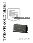
Download Campbell RTMS SYSTEMS Instruction manual
Transcript
RF FOR RTMS SYSTEMS INSTRUCTION MANUAL REVISION: 3/95 COPYRIGHT (c) 1995 CAMPBELL SCIENTIFIC, INC. WARRANTY AND ASSISTANCE The RF FOR RTMS SYSTEMS are warranted by CAMPBELL SCIENTIFIC, INC. to be free from defects in materials and workmanship under normal use and service for twelve (12) months from date of shipment unless specified otherwise. Batteries have no warranty. CAMPBELL SCIENTIFIC, INC.'s obligation under this warranty is limited to repairing or replacing (at CAMPBELL SCIENTIFIC, INC.'s option) defective products. The customer shall assume all costs of removing, reinstalling, and shipping defective products to CAMPBELL SCIENTIFIC, INC. CAMPBELL SCIENTIFIC, INC. will return such products by surface carrier prepaid. This warranty shall not apply to any CAMPBELL SCIENTIFIC, INC. products which have been subjected to modification, misuse, neglect, accidents of nature, or shipping damage. This warranty is in lieu of all other warranties, expressed or implied, including warranties of merchantability or fitness for a particular purpose. CAMPBELL SCIENTIFIC, INC. is not liable for special, indirect, incidental, or consequential damages. Products may not be returned without prior authorization. To obtain a Returned Materials Authorization (RMA), contact CAMPBELL SCIENTIFIC, INC., phone (435) 753-2342. After an applications engineer determines the nature of the problem, an RMA number will be issued. Please write this number clearly on the outside of the shipping container. CAMPBELL SCIENTIFIC's shipping address is: CAMPBELL SCIENTIFIC, INC. RMA#_____ 815 West 1800 North Logan, Utah 84321-1784 CAMPBELL SCIENTIFIC, INC. does not accept collect calls. Non-warranty products returned for repair should be accompanied by a purchase order to cover the repair. 815 W. 1800 N. Logan, UT 84321-1784 USA Phone (435) 753-2342 FAX (435) 750-9540 www.campbellsci.com Campbell Scientific Canada Corp. 11564 -149th Street Edmonton, Alberta T5M 1W7 CANADA Phone (403) 454-2505 FAX (403) 454-2655 Campbell Scientific Ltd. Campbell Park 80 Hathern Road Shepshed, Leics. LE12 9RP ENGLAND Phone (44)-50960-1141 FAX (44)-50960-1091 RF FOR RTMS SYSTEMS TABLE OF CONTENTS PAGE SECTION 1. GENERAL RADIOTELEMETRY NETWORK 1.1 1.2 1.3 1.4 Introduction............................................................................................................................. 1-1 Field Station............................................................................................................................ 1-2 Base Station ........................................................................................................................... 1-3 Repeater................................................................................................................................. 1-4 SECTION 2. ASSEMBLING THE RADIOTELEMETRY NETWORK 2.1 2.2 2.3 2.4 2.5 2.6 2.7 Final Layout ............................................................................................................................ 2-1 Install Base Station................................................................................................................. 2-1 Install Nearest Repeater/Field Station.................................................................................... 2-2 Test the Radiotelemetry Link.................................................................................................. 2-3 Troubleshooting Unsuccessful Communication Attempts...................................................... 2-3 Adding Stations to the Net Description................................................................................... 2-4 Radio Test Results ................................................................................................................. 2-4 SECTION 3. RADIOTELEMETRY NETWORK COMPONENTS 3.1 3.2 3.3 3.4 3.5 The RF95T Modem ................................................................................................................ 3-1 RF100/RF200 Radios............................................................................................................. 3-4 Antennas and Cables ............................................................................................................. 3-5 Tripods, Towers, Enclosures and Power Supplies................................................................. 3-7 RF232T Base Station ............................................................................................................. 3-8 SECTION 4. OPERATION OF THE RADIOTELEMETRY NETWORK 4.1 4.2 RTMS Notes ........................................................................................................................... 4-1 GraphTerm for DOS Version 2.2 or Newer ............................................................................ 4-3 APPENDICES APPENDIX A. SETTING THE STATION ID ...........................................................................A-1 APPENDIX B. ALTERNATE BASE STATION CONFIGURATIONS ..............................B-1 APPENDIX C. POWER CALCULATIONS ..............................................................................C-1 APPENDIX D. FUNDAMENTALS OF RADIOTELEMETRY .............................................D-1 GLOSSARY i SECTION 1. GENERAL RADIOTELEMETRY NETWORK 1.1 INTRODUCTION Data retrieval from a remote site can be difficult. To accomplish data collection from isolated sites Campbell Scientific, Inc. utilizes a radiotelemetry network. Dataloggers can be accessed by radiotelemetry which requires no physical connection from the computer to the datalogger. The radiotelemetry link reduces the number of visits to a remote site for data collection. The radiotelemetry network is designed for complete computer control. One computer can establish communication with up to 254 remote sites (150 per RF232T). The RTMS allows data collection from the datalogger, transmitting datalogger programs, and displaying current readings from the datalogger. The requirements specific to a radiotelemetry network include: • The distance between radio stations should not be greater than approximately 25 miles. • The stations should not have major obstacles between them, therefore, they should be within line-of-sight of each other. The stations communicate over a radio frequency which is specified in Megahertz (MHz). A data communication network must have its own specific frequency to prevent interference from other sources. Typical radio frequencies are either VHF (Very High Frequency) ranging from approximately 130 to 174 MHz or UHF (Ultra High Frequency) ranging from approximately 403 to 512 MHz. A typical RF system is shown in Figure 1-1. Telemetry network’s three basic components are: • • • Field Station Base Station Repeater Station FIGURE 1-1. A Basic Radiotelemetry Network 1-1 SECTION 1. GENERAL RADIOTELEMETRY NETWORK 1.2 FIELD STATION Purpose: The field station is where the measurements are made. The Campbell Scientific datalogger resides at this station taking the desired measurements. Any field station can also operate as a repeater. The only requirement is that the station’s antenna must be able to communicate in all desired directions. This may require an omnidirectional antenna. Equipment Required: • • • • • Radio RF Modem Antenna and antenna cable Datalogger Power supply, enclosure, sensors, and mounting needs ANTENNA FIGURE 1-2. CR10 Field Station 1-2 SECTION 1. GENERAL RADIOTELEMETRY NETWORK 1.3 BASE STATION Purpose: A base station utilizes a computer to collect data from the field station(s). Normally, all communication to the field stations originate at the base station. Data retrieval, remote programming, and system analysis can all be done from the base station. Equipment Required: • • • • • Radio RF Base Station OS/2 Computer with RTMS software Antenna and antenna cable AC power FIGURE 1-3. Base Station 1-3 SECTION 1. GENERAL RADIOTELEMETRY NETWORK 1.4 REPEATER Purpose: To act as relay between two communicating stations separated by too long of a distance or an obstacle which impedes direct communication. A repeater is not always required in a radiotelemetry network. A field station can also function as a repeater. Equipment Required: • • • • • Radio RF Modem Antenna and antenna cable 12V and 5V power supply (PS512M) Enclosure and other mounting needs FIGURE 1-4. Repeater 1-4 SECTION 2. ASSEMBLING THE RADIOTELEMETRY NETWORK This section provides a logical order for RF network assembly and deployment. Details of specific components in the system are described in Section 3 “Radiotelemetry Network Components.” This component section is cross-referenced throughout this assembly section. 2.1 FINAL LAYOUT The initial locations of the base, field, and repeater stations have likely been determined already. Locate RF stations on an area map, preferably a topographic map. Draw a line along every communication path. Each field station must have a path connecting it back to the base station. No path can be going through a mountain or large obstacle; this would negate the line-of-sight requirement. A station may need to be moved or a repeater station may need to be added if this requirement is not met. At each station there is an RF modem. Each modem requires a unique ID number (Station ID). The number may range from 1 to 254. On the map, label the base station as 1. Label the remaining stations with different ID numbers. Later, each modem will be set with the corresponding ID number. The Station ID, similar to a phone number, allows the base station to call many different field stations. 2.2 INSTALL BASE STATION 2.2.1 BASE STATION HARDWARE 4. Mount the base station antenna in a location that is higher than any surrounding buildings or obstacles. Refer to Section 3.3 for more information on mounting the antenna. 5. After the antenna is mounted, connect the coax cable between the antenna and the BNC connector mounted in Step 2. 6. Replace the cover of the RF232T. 7. Connect a large gauge (approximately 8 AWG) copper wire from the antenna to a good earth ground. This is for lightning protection. This is required for any antenna, especially if the coax cable from the antenna goes inside a building. 8. Connect a 25-pin RS232 cable from the computer serial port to the RF232T. 9. After verifying that the RF232T power switch is off, plug in the RF232T's wall transformer. 2.2.2 REAL TIME MONITORING SOFTWARE (RTMS) The major component of the base station is the RF232T Base Station. Refer to Section 3.5 for locational drawings and a description of the RF232T Base Station. With the base station hardware installed, RTMS must be setup if it is not already. Refer to the RTMS manual for specific information on installing RTMS and for specific information on the programs described here. 1. Remove the top of the RF232T by unscrewing the four screws on the sides. The major components of RTMS are: 2. Remove the radio and its cable from its mounting bracket. Mount the radio directly onto the bottom of the RF232T. Secure the BNC connector from the radio's cable to its hole on the back of the RF232T. See Figure 3-7 for assistance. • NetAdmin − Network administration and health • RTM − Real Time Monitor for graphical display of real-time data. • DBSelect − Data collection and routing. 3. Connect the radio to 12 V, ground, and the RF Modem. The RF modem is located behind the front panel above the "POWER ON" light. See Figure 3-8 for assistance. • DLSMGR − Provides the actual communication with dataloggers. CAUTION: Radio transmission without an antenna connected can damage the radio. 2.2.3 NET DESCRIPTION Ultimately, NetAdmin will be used to describe the entire network for ongoing communication with dataloggers in the RF network. However 2-1 SECTION 2. ASSEMBLING THE RADIOTELEMETRY NETWORK when a valid network description containing remote sites is “made active” attempts to communication with the various remote sites will begin. It is often convenient to test the individual field/repeater first and add them to the network description after proper RF communication is confirmed. This is the process described in this section. 2.2.4 ADDING THE RF BASE TO THE NET DESCRIPTION If the RF base is not already part of the network description, it is necessary to add it. Start the NetAdmin program and select NET DESCRIPTION from VIEW on the main menu. Add RF232T as a child of the computer (PC1). While all of the parameters will eventually need to be set, for now alter only the parameters described here: • Change the station name (STN NAME box) to a name meaningful to users of the system. The default name (RF2) will work but something more recognizable is suggested (i.e., RFBase or Office). Names must start with a letter, contain only letters, numbers, or the ‘_’ character. Names should be unique and be no longer than eight characters. • Check the PORT NAME parameter in the VIA COM PORT box, changing the COM port if necessary. • Set the baud rate to 9600. It is not necessary to add any remote stations (datalogger sites, etc.) to the net description at this time. They can be added after the radio links are tested. 2.2.5 TESTING COMMUNICATION WITH THE RF BASE When the RF base has been properly described, select MAKE THE OPEN NET DESCRIPTION ACTIVE under the FILE option on the main menu. NetAdmin will prompt for a file name to save the description if it was not already saved. Normally it is a good idea to save the description. Close the Net Description view. Notice the main NetAdmin screen. The RF base station should be shown on the display. Its color will indicate the last type of message about this station. If the site is black, no communication has been attempted yet. If the site is red or 2-2 blue than a warning or fault message has occurred. If the site is green, successful communication has occurred. Select STATUS/WARNING/FAULT under VIEW on the main menu to see the messages. If “Serline Timeout Retry On COM?” or a “Link Failed” fault message has occurred there maybe a communication problem. See Section 2.2.6. To verify communication with the RF base select RF LINK TEST found under VIEW on the NetAdmin main menu. Select the RF base station named in the box in the upper left area of the view. Move the cursor to the [REPEATER] SWITCH SETTING box. Enter the ID as set with switches for the RF232T base. RF232T bases are normally shipped from the factory with an ID of 1. Select the BEGIN button. If communication between the computer and the RF232T is successful the TEST STATUS/RESULTS box will show the PROM signature for the RF232T. If the test is successful, remote sites can be set up. 2.2.6 IF TEST FAILS Make sure the RF232T is plugged in and is turned on. When powered, the RF232T Carrier Detect Light should blink twice to indicate a successful memory check. If the light is blinking continuously, there is a hardware problem (see Section 3.1.4 for more information on the Carrier Detect Light). • Check the Net Description and verify the COM port and baud rate settings. If the description is changed it must be “made active” for the changes to take effect. • Check that the serial cable is properly attached to the computer and the RF232T. It should not be a “Null Modem“ cable. • Check that the SC12 9-pin ribbon cable inside the RF232T is connected from the small circuit board to the RF95T modem. 2.3 INSTALL NEAREST REPEATER/ FIELD STATION The order in which a general RF field station should be installed, follows. A repeater station is installed in the same order. For instructions on installing any particular component, refer to either Section 3 of this manual or the Weather Station Manual. SECTION 2. ASSEMBLING THE RADIOTELEMETRY NETWORK 1. Tripod or tower 2. Enclosure and datalogger - Turn on datalogger. 3. Antenna - Orient correctly; remember direction and polarization. 4. Solar Panel 5. Power Supply 6. Sensors 7. RF Modem - Set the Station ID according to the map. 8. Radio - Make sure to connect to RF Modem and to power supply. Connect to antenna before turning on. 2.4 TEST THE RADIOTELEMETRY LINK With a field station or repeater installed, return to the base station for initial testing of the communication link. An RF link can also be tested at the field site with a portable base station; hardware requirements for the portable base station are described in Appendix B. At the computer site, start NetAdmin. Select RF LINK TEST found on the VIEW menu. It is not necessary to add the field station or repeater to the net description to test the communication link. As before, select the RF base in the upper left box. Move the cursor to the [REPEATER] SWITCH SETTING box. Enter the ID for the remote site as set with its switches. Select the BEGIN button. If the test is successful the signature of the remote RF95T PROM along with the quality numbers will be displayed. The test may take several minutes to complete. The quality numbers should be examined as they will help indicate potential problems like outside interference on the frequency or marginal links. These numbers are explained in Section 2.7. 2.4.1 A SUCCESSFUL TEST After a successful test, set up the next nearest site and test that telemetry link. If a repeater is to be utilized to communicate with a site, enter the ID of the repeater followed by the ID of the field site in the [REPEATER] SWITCH SETTING box. Separate the ids with a space. When the BEGIN button is selected the entire link will be tested. The signature of the remote site will still be returned. An additional row of quality numbers will be returned for each repeater. 2.4.2 AN UNSUCCESSFUL TEST If the base cannot communicate with the remote, a TEST FAILED message will be displayed in the TEST STATUS/RESULTS box. For links not using a repeater, the problem could be at the base or the remote site. Section 2.5.1 gives some suggestions that can be tried. For links utilizing repeaters, start by testing the link between the RF base and the repeater. It is not necessary to have a datalogger at a repeater site to test communication with the RF TEST LINK. As each part of the link is verified, add the next segment and test again. With this method it should be possible to determine which segment is failing. 2.5 TROUBLESHOOTING UNSUCCESSFUL COMMUNICATION ATTEMPTS 2.5.1 TROUBLESHOOTING PHYSICAL LINK BETWEEN BASE AND REPEATER/FIELD STATION When communication is not established, troubleshooting begins with the simplest RF link in the system, which is usually communication with the nearest field station. There is NO substitute for first checking the hardware connections, Station IDs, and everything listed in the previous sections. Below are a few additional items to check: 1. Antenna is used in proximity of metal. 2. Transmission from inside a building. 3. Damaged or shorted cables. 4. Bad or improper connections. 5. Antenna frequency does not match the radio frequency. 6. Base and field station radios aren't using same frequency. 7. Datalogger power drops below 9.6 Volts during RF transmission. Use datalogger Instruction 10 or volt meter. If the field station's RF95T Modem's Carrier Detect light goes on during a test, then at least a signal is reaching the site. If this occurs, check the following: 2-3 SECTION 2. ASSEMBLING THE RADIOTELEMETRY NETWORK 1. RF modem's ID matches ID in the RF Path. 2. Field station's radio and datalogger have sufficient power. 3. Radio is connected to RF modem. 4. RF modem is the only thing connected to datalogger's 9-pin connector. 2.6 ADDING STATIONS TO THE NET DESCRIPTION It is possible to deploy the entire RF datalogger network, testing the RF links as they are installed, without adding any of the remote site to the Net Description. Some users find this technique desirable. On many other networks it may be desirable to start data collection from sites as soon as possible and the sites should be added to the Net Description after their links have been tested. The testing of RF links can continue concurrently with data collection and other RTMS functions. Some functions may be delayed slightly due to a RF test or the RF test may have to wait on other operations. These delays are usually not significant. Experience has shown that it is desirable to verify an RF link with the RF TEST LINK before adding stations to the Net Description that utilize that link. Before adding remote stations to the description, return to the parameter for the RF base and ensure that they are set correctly. The Polling Interval needs to be set for correct operation as it determines the rate at which the remote dataloggers are checked for data. Add the remote field sites as children of the RF base. Repeater only sites are not added as nodes. To utilize a repeater (either a repeater only site or another field site) simply precede the remote’s ID with the repeater's ID in the VIA RF MODEM box in the remote’s station parameters. Separate the IDs with a comma. Section 5.1 of the RTMS manual gives additional information on creating Net Descriptions. Be sure to make the current description active if any changes are made. 2-4 2.6.1 NETWORK HEALTH DISPLAY AND ERROR, WARNING, AND STATUS MESSAGES As remote sites are added to the network description, they also appear on the network health display (NetAdmin main screen). The color of the site indicates the type of the last message about that station. Red indicates a fault message, blue indicates a warning message, green indicates a status message (usually successful communication), and black indicates no communication has been attempted. Selecting STATUS/WARNING/ FAULT under VIEW on the main menu will display a box displaying these messages. See Section 5.5 of the RTMS manual. Messages regarding remote RF sites are: • Broadcast failure − A remote did not respond to a broadcast message. • Poll failure − A remote did not respond to a broadcast message or retries. • Bad link − A remote did not respond to a direct attempt to communicate with it. Link will be marked bad. • Communication restored − A link that was previously marked bad has been restored. See Section 3.1.5 for more information on how RF communication takes place. 2.7 RADIO TEST RESULTS Completed link test results are shown in the "Test Status/Results" box. If successful, test results show the PROM signature of the RF modem whose switch setting is last in the RF path, and a communication "Quality Report" with a record for each hop specified in the path. The number of "Quality Records" reported in the test response depends on the number of RF modems listed in the RF path. If one remote node is listed in the command then there will be two quality records. The first record shows how well the remote node was able to receive from the base, the second shows how well the base was able to receive from the remote. With two or more modems listed in the path, the first quality record will indicate how well the most remote modem received. The rest of the quality records show how well data was received with each hop going from the most remote node back to the base. So, if two RF modems were listed in the test path, there would be three quality records in the response. The SECTION 2. ASSEMBLING THE RADIOTELEMETRY NETWORK second quality record would apply to how well the repeater received from the remote, and the third record would apply to how well the base received from the repeater. A "Quality Record" is made up of five values as follows: First Value Second Value Third Value Fourth Value Fifth Value test packet size; front of 2T envelop; back of 2T envelop; front of 1T envelop; back of 1T envelop. The "test packet size" is usually around 238, but varies a little depending on network layout. This value will be half or less of the expected 238 if packets are being lost for one reason or another. For example, if packets are being walked on by outside RF activity, the test packet will not make it though and will be retransmitted at a smaller size. Over RF, data is transferred as a stream of bits encoded into short and long periods of time between transitions. We call the short time a "1T" period and the longer a "2T" period. Each transition is expected to fall within a certain window of tolerance to be valid. If there is too much error in the signal and the transition falls outside its allotted window, the packet will be in error and be retried. As a packet is received the RF95T keeps track of the transition that occurred closest to the front of the allowable window and closest to the back. These values are kept for both the 2T and 1T windows and are the last four values of the "Quality Record". Both windows are 204 ticks long, so if the transmission was perfect, the data envelope front and back would both be close to 102. The closer the front value gets to 0 and the closer the back value gets to 204, the worse the quality. 2-5 SECTION 3. RADIOTELEMETRY NETWORK COMPONENTS 3.1 THE RF95T MODEM As with the CR10 and CR10T datalogger, there are enough changes to the RF modems to warrant a new model name hence the RF95T and the RF232T. The RF95T and the RF232T differ from the RF95 and RF232 in the following respects: • The “T” versions use a new protocol requiring a different PROM. • The “T” versions are not supported by PC208. • The “T” versions use a larger capacity RAM chip. RF95 and RF232 modems can be updated by purchasing an upgrade kit with the new PROM and RAM chip for serial numbers starting at about 1491. RF95 modems that are older than this had the RAM chip soldered in place and should be returned to Campbell Scientific for the necessary modifications. The DC95 modem and SDC hardware can't be used or upgraded. The following capabilities are important when using RTMS, CR10T, and RF95T modems: • A maximum depth of four repeaters can be used. • 150 is maximum number of remote RF95TCR10T site that may be used with an RFBase. A maximum of 254 remotes can be used on a PC. • Phone to RFBase stations with a CR10T at the site are NOT supported • RF95T and RF232T modems can't be used in a network containing RF95 and RF232 modems. • CR10, 21X, and CR7 dataloggers can't be used with RF95T and RF232T modems. 3.1.1 PHYSICAL DESCRIPTION The front panel of the RF95T is shown in Figure 3-1. There are two ports for interfacing external devices. The port labeled TRANSCEIVER connects to the radio, and the port labeled SERIAL I/O connects to the datalogger, PS512M or CH512R in the case of a repeater or phone-to-RF base station. The red light labeled CARRIER DETECT is used primarily to indicate when a carrier frequency has been detected by the radio. This is explained later in further detail. FIGURE 3-1. The RF95T Modem 3-1 SECTION 3. RADIOTELEMETRY NETWORK COMPONENTS 3.1.2 RF95T STATES The ninth switch should be set in the RF95T-ME state (switch nine should be open, represented by a 1). Refer to Figure 3-2. The RF95T is shipped with the switch set for the RF95T-ME state. TABLE 3-1. A Sample of Station ID Numbers and the Corresponding Switch Settings * Station ID Switch Settings 56789 1234 0 10 20 30 40 50 60 70 80 90 100 110 120 130 0000 0101 0010 0111 0001 0100 0011 0110 0000 0101 0010 0111 0001 0100 0000X 0000X 1000X 1000X 0100X 1100X 1100X 0010X 1010X 1010X 0110X 0110X 1110X 0001X Station ID 255 is reserved for phone-to-RF base stations. 3.1.3 SETTING STATION ID Each RF95T must have a Station ID, which is similar to a phone number. This allows one base station to communicate with any one particular field station. The Station ID can be any number from 1 to 255, the Station ID is set with the switch inside the RF95T. The first eight dip switches are used to set the Station ID. Table 3-1 shows the switch setting for several Station IDs numbers, Appendix A shows all possible Station ID numbers. The dip switches can either be open, represented by 1, or closed, represented by 0; X in Table 3-1 refers to "don't care." The ninth dip switch is set according to the desired RF95T state, see Section 3.1.2 "RF95T States." The RF95T is shipped with a Station ID of 1, and is set in the RF95T-ME state. FIGURE 3-2. Setting the Station ID 3.1.4 THE CARRIER DETECT LIGHT The Carrier Detect Light on the front panel of the RF95T has several purposes. The primary function of the light is to indicate when data is being received or transmitted. The light will stay on when a network frequency originating from another RF95T is detected. If a signal is detected that isn't intended for that station, the light will shut off after about two-tenths of a second. The Carrier Detect Light can also be used to check the RAM (Random Access Memory) and ROM (Read Only Memory) of the RF95T. With the radio disconnected and the datalogger in the LOG (*0) Mode, connect the datalogger to the RF95T Serial I/O Port with a 9-pin ribbon cable. The sequence of the light flashing after connection indicates the RAM and ROM status. Both the RAM and ROM are good if the light goes on for one second, off for one second, and then back on for one second. The RAM is faulty if the light is on for one half second and off for one half second, continuously. The ROM is faulty if the light goes on for one second, off for one half second, on for one half second, and then off for one half second, continuously. 3.1.5 THEORY OF OPERATION Understanding how the radio network works will aid in both designing and maintaining a RF network. The communication between the computer and the dataloggers in a radio network are managed by the RFBase and occur somewhat independently of the computer. There are two basic packet delivery techniques provided by the RF232T (RFBase) and the RF95T (remote) modems; direct maintenance and polling. These are described in the following sections. 3-2 SECTION 3. RADIOTELEMETRY NETWORK COMPONENTS Packet are routed from the computer to the dataloggers on demand. These maintenance type operations include the following: • Clock set or check. • Datalogger program download. • Get table definitions (query the datalogger to see what data it has). • Data advise notification (start, stop, or modify a data collection session with datalogger). If the RFBase is busy when in receives one of these packets it will hold it until it is free. The RFBase will only hold one of these operations in its queue. These “transactions” conclude when the datalogger returns a valid result code. Packets generated by the dataloggers (other than response codes to computer initiated maintenance commands) are not routed on demand, rather the datalogger is periodically checked for any computer bound packets. The user-specified Polling Interval determines how often the dataloggers are checked. These type of packets include data and any status, warning or fault messages the datalogger generates. The RFBase provides this polling independently of the computer. 3.1.5.1 Areas The RFBase is given a description of the network along with the polling interval. For maintenance type transactions, the RFBase routes packet directly to and from the datalogger using the user specified repeaters if any. For polling, the RFBase divides the RF network into areas. An area consists of one or more remote RF95T and dataloggers sites that are accessed by the same communication path. If the number of remotes in a given area exceeds 40, then that area is broken into smaller areas. For example, if a network had five remotes all accessed directly from the RFBase then it would contain one area. If all five remote were accesses through a common repeater then there would still be one area. If three of the remotes were accessed directly and two were accessed through a common repeater there would be two areas. The RF network is polled one area at a time. 3.1.6 RF95T MODEM COMMUNICATION PROTOCOL Polling begins with the RFBase (or last common repeater) sending a single short broadcast to all remotes in the affected area. Each remote RF95T upon receiving the broadcast checks the local datalogger for any computer bound packets by raising the dataloggers ring line and enter telecommunications. The remote RF95T buffers any packets it receives and exits telecommunications with the datalogger. The remote RF95T modems will then send the packets to the RFBase or repeater that issued the broadcast. Each remote RF95T responds during a predetermined time window so the remotes do not conflict with each other. In the network example with five remotes, all accessed directly by the RFBase the sequence would be as follows: broadcast by base, response from first remote, response from second remote, and so on until all five have responded. The response windows are assigned by the base. If a remote has more data then it can send during its response window it responds with a special packet indicating it has too much data. The base (or broadcasting repeater) will then accessed this remote after the poll and collect its data directly. The RFBase holds all data it receives until it is checked for packets by the computer. A broadcasting repeater will return to the packets it received to the RFBase after the repeater finishes polling its area. 3.1.6.1 Retries on polling If a polled remote RF95T fails to respond to the broadcast, the RFBase or broadcasting repeater will attempt 3 retries at the end of each poll for all sites that did not respond. A “Broadcast failure” messages will also be sent to the computer. These retries take 2 to 3 seconds per site. If the retries also fail, a “Polling Failure” message is also sent. These retries take place after each polling cycle of the affected area. Normally a remote will fail to respond only if it is unable to receive or transmit due to a hardware or power supply problem. These retries may affect the polling of the network when the polling interval is close to the actual time required to poll the network. 3.1.7 RETRIES ON DIRECT MAINTENANCE TRANSACTIONS If a remote RF95T fails to respond to a direct maintenance transaction, retries will be attempted for approximately one minute. If the remote does 3-3 SECTION 3. RADIOTELEMETRY NETWORK COMPONENTS not respond during this time, a “Bad Link” error messages is returned. The RFBase marks that remote as bad and will return a “Bad Link” message each time the computer attempts to send packets to that site. The RFBase will continue to include the failed remote as part of the polling process. If the remote ever responds to a poll, a “Communication restored” message will be sent, and the RFBase will again accept direct maintenance packets for that remote. 3.1.8 RF95T CONNECTIONS 3.1.9 RF95T CURRENT DRAIN Quiescent Wait * Active 1.4 mA 3-4 mA 30 mA * Waiting to respond to broadcast. Usually the radio current drain is the relevant factor in battery power calculations. 3.2 RF100/RF200 RADIOS 3.2.1 RADIO DESCRIPTION The 9-pin Serial I/O connector is normally used to connect the RF95T to the datalogger, PS512M, or CH512R. Table 3-4 describes the 9-pin connections. The 10-pin rectangular connector is for connection to the transceiver. Table 3-6 contains the pinout for the radio to modem cable descriptions. TABLE 3-4. Serial I/O Connector Description Pin Description 1 2 3 4 5 6 7 8 9 +5 V: Supply from external source GND: Ground Ring: Ring to datalogger RXD: Transmit from RF95T ME: Modem Enable from datalogger Printer Enable: Not used Unload Enable: Not used Tape Enable: Not used TXD: Received by RF95T The RF100 and RF200 are used in Campbell Scientific's RF applications to transmit and receive data blocks. The radios shipped from Campbell Scientific are secured on a mounting bracket designed to fasten on the top of the RF modem (see Figure 3-3). The mounting bracket also supports a BNC Jack connector from the radio. The coax cable that is required to connect the radio to its antenna should be connected to the radio at this BNC connector. See Section 3.3 for more information on the antenna cable. The RF100/RF200 Radios are connected to the RF modem by a special radio cable. The first 10-pin connector on this radio cable has a red and black wire coming out of the connector. This is the 10-pin connector (labeled "radio") that should be connected to the radio. The red and black power wires should be connected to 12V and Ground respectfully. The second 10pin connector (labeled "modem") should be connected to the RF modem. Table 3-6 contains the pin out of this radio cable. FIGURE 3-3. RF100 On Bracket with Connector 3-4 SECTION 3. RADIOTELEMETRY NETWORK COMPONENTS 3.2.2 RADIO SPECIFICATIONS The RF100 and RF200 radios are manufactured by E.F. Johnson. Campbell Scientific modifies the radios to work with the RF95T Modem. Table 3-5 contains a list of the main radio specifications. TABLE 3-5. Main Radio Specifications RF100 VHF RF200 UHF Channel Capability Dimensions (w/o mounting) Operating Temperature Range Emissions Designator Deviation 3420 4W 132-142, 142-150, 150-162, 162-174 1 3.6" x 2.9" x 2.2" -30°C to +60°C 16KOF2D ± 2.5 kHz 3410 5W 403-430, 430-450, 450-470, 470-512 1 3.6" x 2.9" x 2.2" -30°C to +60°C 16KOF2D ± 2.5 kHz Current Drain Quiescent Active 30mA 1.7 A 30mA 1.5 A E.F. Johnson Model No. Power Output Frequency (MHz)* * DOC Compliance for 138-174 MHz and 403-470 MHz only. TABLE 3-6. Radio to RF Modem Pin Descriptions RF100/RF200 Radio 10-pin 1 2 3 4 5 6 7 8 9 10 RF95T RF Modem 10-pin 2 7 6 10 open +12V Red Wire 9 3 5 open GND Black Wire 1 3.2.3 RADIO INSTALLATION The RF100 and RF200 Radios are shipped from Campbell Scientific mounted on a special bracket with a cable going from the radio to a BNC connector (see Figure 3-3). The following steps will install a radio for a field or repeater station. 1. Secure the radio and its bracket using the four screws from the RF95T Modem's lid. 2. Connect the 10-pin connector (with the red and black power leads coming out of it) of the radio/RF modem cable into the radio. 3. Connect the second 10-pin connector of the cable into the RF modem. 4. Route the BNC end of the antenna cable through the enclosure conduit. Connect the cable to the BNC Jack connector secured on the radio mounting bracket. 5. Connect the red and black power leads from the radio cable to the 12V and Ground. 3.3 ANTENNAS AND CABLES Antennas radiate and receive the radio signals. Each radio in a radiotelemetry system must have an antenna. A 50 ohm coax cable is used to connect the antenna to the radio. 3.3.1 ANTENNA MOUNTS Antennas must be mounted above any surrounding buildings or obstacles. Antennas must be properly oriented in relationship to the other antennas for RF communications to work. Antennas have various mounting options. Table 3-6 lists mounting specifications for several common Celwave antennas. Specific questions regarding antennas can be directed to Campbell Scientific, Inc. or Celwave. Celwave's address and phone numbers are: Celwave Route 79 Marlboro, NJ 07746 (908) 462-1880 or (800) 321-4700 FAX (908) 462-6919 3-5 SECTION 3. RADIOTELEMETRY NETWORK COMPONENTS 3.3.2 ANTENNA ORIENTATION Antennas must be oriented correctly to allow communication between RF sites. First determine if your antenna is omnidirectional or unidirectional. An omnidirectional antenna will transmit/ receive in a full 360 degree circle. Generally, an omnidirectional antenna will be a straight cylindrical rod which is to be mounted vertically at the top of a tripod. A unidirectional antenna is designed to transmit/receive in a particular direction, or in a specified sector. There are various shapes of unidirectional antennas. The most common is the Yagi antenna (see Figure 1-2). The elements of a Yagi antenna can be mounted either vertically or horizontally, corresponding to either vertical or horizontal polarization. FIGURE 3-4. The PD237 Crossover Plate Antenna Mount Normally, all antennas will be mounted with vertical polarization. Whichever polarization is used, be sure to keep antennas at all sites identically polarized. 3.3.3 ANTENNA CABLES AND CONNECTORS The most common cable type to connect a radio to the antenna is a coaxial RG-8A/U cable. Two connectors are required for each length of cable. The connector for the radio is a BNC type connector. The connector for the antenna is usually either a Type-NM or TypeNF. The BNC, Type-NM, and Type-NF connectors are shown in Figure 3-6. The TypeNM (male) connector is for antennas with a female receptacle, and Type-NF (female) for antennas with male receptacles. FIGURE 3-5. The PD46 Clamp Mount A Campbell Scientific antenna cable complete with connectors is specified as either COAX NM-L or COAX NF-L. COAX NF-L is a coaxial RG-8A/U cable with a BNC connector on one end and a Type-NF connector on the other. See Table 3-7 for cable requirements for common antennas. Due to power loss through the cable, the length of coax cable cannot be extended to any desired length. The amount of power loss is dependent on the radio frequency. RG-8A/U will lose approximately 3.1 dB/100 ft. at 200 MHz and 5.0 dB/100 ft. at 400 MHz. Power loss calculations are reviewed in Appendix C. 3-6 FIGURE 3-6. Type-NM (male), BNC, and Type-NF (female) Connectors SECTION 3. RADIOTELEMETRY NETWORK COMPONENTS TABLE 3-7 Common Antennas and Characteristics VHF or Pipe UHF Cable Gain(dB) O.D. VHF Coax NM-L Unity 3/4" - 2 1/8" VHF Coax NM-L Unity 1" - 2 1/4" VHF Coax NM-L 3.0 1" - 2 1/4" UHF Coax NM-L Unity 1" - 2 1/4" UHF Coax NM-L Unity 3/4" - 2 1/8" Mounting Type U-Bolts U-Bolts U-Bolts U-Bolts U-Bolts Antenna BA1010 BA1012 BA1312 BA6012 BA6110 Type Omni Omni Omni Omni Omni BA6312 PD200 PD201 PD220 PD344 Omni Omni Omni Omni Dipole UHF VHF UHF VHF VHF Coax NM-L Coax NF-L Coax NF-L Coax NF-L Coax NF-L 3.0 5.8 5.0 5.25 4.5 1" - 2 1/4" 1" - 2 3/4" 1" - 2 3/4" 1" - 2 3/4" 2 1/2" U-Bolts PD46 (Fig 3-5) PD46 (Fig 3-5) PD46 (Fig 3-5) Clamps PD390S PD400 PD688S PD1107 PD1121 Yagi Omni Yagi Omni Dipole VHF VHF UHF VHF VHF Coax NF-L Coax NM-L Coax NF-L Coax NF-L Coax NF-L 8.0 7.5 10.0 3.0 3.0 1 5/16, 2 1/4, or 2 3/8 1" - 2 3/4" 1 5/16" - 2 1/4" 1" - 2 3/4" 2 1/2" PD37 (Fig 3-4) PD46 (Fig 3-5) U-Bolts PD46 (Fig 3-5) Clamps 3.4 TRIPODS, TOWERS, ENCLOSURES, AND POWER SUPPLIES There are several methods of mounting and housing sensors and other equipment for a station. 3.4.1 TRIPODS AND TOWERS FOR MOUNTING For the different mounting requirements, Campbell Scientific offers the CM6 Tripod, CM10 Tripod, UT3 Tower, and UT930 Tower. All mounting options available from Campbell Scientific are rugged instrument mounts that provide sturdy support for Campbell Scientific sensors, enclosures, and measurement electronics. The CM6 and CM10 Tripods can be used as a portable instrument mount in a variety of applications. The UT3 and UT930 Towers provide a more sturdy long-term support 3.4.2 ENCLOSURES Enclosures are needed to keep water and debris from damaging the data acquisition equipment. Campbell Scientific, Inc. enclosures are designated as “raintight,” and are designed to mount on a tripod. Following is a description of the standard enclosures. Campbell Scientific offers two enclosures for housing a CR10T and peripherals. The fiberglass enclosures are classified as NEMA 4X (water-tight, dust-tight, corrosion-resistant, indoor and outdoor use). A 1.25” diameter entry/exit port is located at the bottom of the enclosure for routing cables and wires. The enclosure door can be fastened with the clasp for easy access. The enclosure’s clasp door can be secured with a basic lock. Both enclosures are white for reflecting solar radiation, reducing the internal temperature. The Model ENC 12/14 fiberglass enclosure houses the CR10T and power supply, and one or more peripherals. Inside dimensions of the ENC 12/14 are 14" x 12" x 5.5", outside dimensions are 18" x 13.5" x 8.13" (with brackets); weight is 11.16 lbs. The model ENC 16/18 fiberglass enclosure houses the CR10T and power supply, and two or more peripherals. Inside dimensions of the ENC 16/18 are 18" x 16" x 8.5." Outside dimensions are 21.75" x 21" x 11" (with brackets); weight is 17.2 lbs. 3.4.3 POWER SUPPLY A radiotelemetry network requires a reliable power supply at each station. A solar panel or 110/220 VAC charging source is normally required due to the large current drain of the radio. 3.4.3.1 Lead Acid Batteries Lead acid batteries are designed to be float charged by a solar panel or AC power source. The role of the lead acid battery is to supply power when the charging source is absent, e.g. in case of power failures (AC charging), or during times of zero charge with a solar panel. 3-7 SECTION 3. RADIOTELEMETRY NETWORK COMPONENTS 3.4.3.2 PS12LA Lead Acid Power Supply The PS12LA power supply includes a 12V, 7.0 amp-hour lead acid battery, AC transformer, and a temperature-compensated charging circuit with a charge indicating diode. An AC transformer or solar panel should always be connected to the PS12. The charging source trickle charges the lead acid batteries which power the datalogger. The internal lead acid battery continues to power the datalogger if the charging source is interrupted. The PS12LA specifications are given in Table 3-8. incorporate this instruction into their data acquisition programs to keep track of the state of the power supply. If the system voltage level consistently decreases through time, some element(s) of the charging system has failed. Instruction 10 measures the voltage of the lead acid battery. External power sources must be disconnected from the CR10T and charging circuit in order to measure the actual lead acid battery voltage. TABLE 3-8. PS12LA Battery and AC Transformer Specifications The two leads from the charging source can be inserted into either of the CHG ports on the PS12LA wiring strip; polarity doesn’t matter. A tranzorb provides transient protection to the charging circuit. A sustained input voltage in excess of 40V will cause the tranzorb to limit voltage. Lead Acid Battery Battery type Float life @ 25°C Capacity Shelf life, full charge Charge time, (AC Source) Some solar panels are supplied with a connector. This connector must be clipped off so the two wires can be inserted into the two terminal ports. AC Transformer Input: Isolated output: The red charge light is on when AC power or a solar panel is connected to the PS12. If the input voltage is high enough, the battery will charge even when the datalogger is on. 3.4.3.3 PS512M Voltage Regulator with Null Modem Ports. CAUTION: Switch the power to OFF before disconnecting or connecting the power leads to the Wiring Panel. The Wiring Panel and PS12LA are at power ground. If 12V is shorted to either of these, excessive current will be drawn until the thermal fuse opens. The external port, labeled EXT, is not meant to be used with the PS12LA. The primary power source is the charging source, and the secondary power source is the internal lead acid battery. Connecting a lead acid battery to the external source is the same as connecting two lead acid batteries in parallel, causing one battery to drop voltage and the other to raise voltage. Alkaline batteries connected to the external port would be charged by the charging source, which can cause an explosion. CAUTION: Do not use the external port, labeled EXT, with the PS12LA. Monitor the power supply using datalogger Instruction 10. Users are strongly advised to 3-8 Yuasa NA 7-12 5 years typical 7.0 amp-hour Check twice yearly 40 hr. full charge 20 hr. 95% charge 120V AC, 60 Hz 18V AC @ 880 mA max. The PS512M 12 Volt Lead Acid Power Supply with Charging Regulator and Null Modem Ports is used when 5 volts is needed to power CSI's external modems through the 9-pin serial ports. The PS512M supplies 5 volts to pin 1 of the 9pin null modem ports, otherwise the capabilities and functions are identical to the PS12LA. A common use for the PS512M is in radiotelemetry networks. The PS12LA cannot be modified to the PS512M. The maximum current drain on the 5 volt supply of the PS512M is 150 milliamps. 3.5 RF232T BASE STATION 3.5.1 RF232T INTRODUCTION The RF232T Base Station provides a "single box" desktop base station with the following features: • Internal RF modem. • 25-Pin RS232 port for connection to IBM PC. • 110 VAC/12 VDC transformer and mount for the base radio. • Easy access to radio for antenna cable connection. SECTION 3. RADIOTELEMETRY NETWORK COMPONENTS The RF232T Base Station includes an RF95T Modem with a carrier detect light. The RF95T Modem sits directly behind the RF232T front panel. For a description of the Carrier Detect Light and the communication protocol, refer to Section 3.1 "RF95T Modem." The Station ID Number of the RF95T comes shipped from the factory at 1. Under most circumstances there is no need to change this address. The RF232's 25-pin female port connects to the computer's 25-pin RS232 port. The RF232T's 25-pin port is configured as Data Communications Equipment (DCE) for direct cable connection to Data Terminal Equipment (DTE), such as an IBM-PC serial port. Table 3-9 shows the pin description. 3.5.2 220, 230, AND 240 VAC CONVERSION TABLE 3-9. Pin Description for RF232's 25-Pin Port Pin I/O Description 1 2 3 4 20 22 − I O I I O Ground TX RX RTS DTR RING TABLE 3-10. RF232 Power Conversions Pins Jumpered 110 VAC 120 VAC 220 VAC 230 VAC 240 VAC 1-3, 2-4 1-3, 2-4 2-3 2-3 2-3 Apply AC 1-4 1-4 1-5 1-4 1-4 The RF232 can be used with 220, 230, or 240 VAC if a small wiring modification is done. 1. First, disconnect any AC power! 2. Lift the cover off the RF232 and locate the power supply (P/N 4918) as shown in Figure 3-8. 3. Unscrew the four Phillips-head screws on top of power supply and turn power supply upside down. 4. Clip the wire ties holding the power supply leads to the base. 5. With the power supply on its back, locate pins 1 through 5. The power supply is shipped from the manufacturer configured for 120 VAC with pins 1 and 3 jumpered, pins 2 and 4 jumpered, and AC power coming onto pins 1 and 4. These connections must be desoldered. 6. Resolder the pins as shown in Table 3-10 for the Power Conversion you require. FIGURE 3-7. The RF232T Base Station 3-9 SECTION 3. RADIOTELEMETRY NETWORK COMPONENTS FIGURE 3-8. Top View of the RF232T Base Station 3-10 SECTION 4. OPERATION OF THE RADIOTELEMETRY NETWORK All field stations can be accessed and monitored from the central base site. Regular visits to the field sites are required to ensure that all sensors are in place, enclosures are dry, solar panel is clean, and that the tripod and antenna are secure. Frequency of visits to the field sites are variable depending on environmental conditions and the sensors utilized. 4.1 RTMS RF NOTES The Real Time Monitoring Software is described in detail in the RTMS manual. This section gives a brief overview and provides specific RF application notes. RTMS is designed so a description of the physical datalogger network is only done once in the NetAdmin program. The programs used for display and archival of data have no RF-specific entries. The module that runs in the background, DlsMgr, provides all communication with the dataloggers and RF modems. NetAdmin provides DlsMgr with a description of the datalogger network. When specifying parameters and understanding the behavior and performance of RTMS, it is important to consider the effects of the communication devices used. 4.1.1 NETADMIN In addition to providing a “Net Description Editor," NetAdmin also provides tools to set and check datalogger clocks, send datalogger programs to the dataloggers, view status-warning-fault messages, do remote keyboard emulation, and test RF links. 4.1.1.1 NET DESCRIPTIONS NetAdmin is used to edit descriptions of the datalogger network in terms of hardware, phone numbers, ID switch settings, and communication addresses. Completed descriptions may be saved. One description is “made active." The active description is used as the basis for all communication with dataloggers in the network. Once a description is active, DlsMgr continues to use it until another description is made active, even if RTMS is completely stopped. If alternative communication paths exist (i.e., a backup repeater in case the main repeater fails), network descriptions utilizing these paths can be created but not made active until needed. Only the RFBase station and datalogger sites are entered as nodes in a RF network description. Repeater-only sites are not entered as nodes. Repeaters (repeater-only sites or sites serving as both a field site and a repeater) are utilized by entering their station ID (switch settings) as part of the path in the VIA RF MODEM box for the [REPTR,] SWITCH SETTING: parameter. Field sites are entered as children nodes of the RFBase. When filling out parameters for the RF network, the following need special RF consideration. POLLING INTERVAL: This determines how often the RFBase polls the remotes for data. It also determines how often the computer polls the RFBase for data. Both are polled at the same interval. The RFBase will attempt to poll its entire network at this rate. This is specified as part of the description of the RFBase. NOTE: Poll at least every 20 minutes. OFFSET: This determines when in the POLLING INTERVAL the computer checks the RFBase for data. Generally, this is used in conjunction with the RF POLL OFFSET parameter to minimize the time the data waits in the datalogger or RFBase. This is specified as part of the description of the RFBase. RF POLL OFFSET: This determines when in the POLLING INTERVAL the RFBase will begin its poll of the remote RF modems. This allows polling to begin after the datalogger has stored it data. For example, if data were being stored every five minutes and the network was polled every five minutes, setting the RF POLL OFFSET to one minute and the OFFSET to four minutes would allow the most recent data to be collected from the dataloggers and the RFBase on most networks. This parameter is specified as part of the description for the first child node of the RFBase. 4-1 SECTION 4. OPERATION OF THE RADIOTELEMETRY NETWORK Do _____ RETRIES USING A _______ SEC PERIOD THEN USE _______ SEC: This allows specifying the rate of reties for a maintenance operation that fails. The intervals must be long enough to allow the operation being retried to complete. Generally, it is a good idea to make these fairly slow as they are not needed unless an operation fails. These are specified as part of the description for the RFBase and the field stations. [REPTR,] SWITCH SETTING: Used to specify the communication path for radio communication. For direct links (no repeaters), enter the station ID set with the address switches at the remote. To utilize a repeater, precede the station ID with the station ID of the repeater(s) to be used. Separate the addresses with commas. This parameter is specified for each of the field stations. 4.1.1.2 SETTING AND CHECKING CLOCKS. NetAdmin has a screen for setting and checking clocks. The following describes some of the settings that are RF dependent. Include the RFBase in the list of stations to have their clocks checked, since the RFBase uses its clock to schedule polling. The RFBase always updates its clock when it receives a command to check or set its clock. It will always read that it was zero seconds off. The IF MORE THAN _____ SECONDS OFF. parameter specifies how far off the clock can be before it will be set. The DlsMgr will attempt to set a given clock (several times if necessary) until it sets the clock within this threshold. For RF networks a value greater than 5-10 seconds is practical. The RESCHEDULE WDOG [MIN]: parameter determines how long DlsMgr will attempt to set the clock at a site before giving up and moving on to the next site. This time should be large enough to accommodate the initial attempt and some retries. 4-2 4.1.1.3 NETWORK HEALTH AND STATUS-WARNING-FAULT MESSAGES The RF-specific messages are described in Section 2.6.1 of this manual. 4.1.1.4 DLD PROGRAM DOWNLOAD EDLOG (also supplied with RTMS) can be used to create and edit datalogger programs (DLD files). NetAdmin can then be used to download these programs to the datalogger. This saves the user from having to travel to the datalogger site to program the datalogger. A large DLD program may take several minutes to download. Several stations can have programs queued up for downloading thus the user can update the programming at several sites without being present to start a new download when the previous one ends. The user should check periodically to ensure that the downloads are progressing as expected. 4.1.1.5 REMOTE KEYBOARD NetAdmin provides remote keyboard emulation. This allows viewing of the datalogger programs and the datalogger * modes. It may take several seconds to see a response to the keys pressed depending on the communication paths and polling interval. If a poll is in progress, it will be finished before the key presses are sent to the datalogger. For this reason, networks that are busy, i.e., where the polling interval is close to the actual time required to poll the network, may be slower as polling is going on all the time. 4.1.2 DISPLAYING DATA WITH RTM (REAL TIME MONITOR) RTM is used to display data as it is collected from the datalogger. While none of the settings in RTM are RF specific, it is important to realize that the frequency of data updates will be directly tied to the polling interval and the RF communication. When strip chart displays are used, RTM will attempt to collect enough old data to backfill the strip chart. This can take several minutes or more when RF is in use. This can be disabled using the BACKFILL enable under OPTIONS on the RTM main menu. SECTION 4. OPERATION OF THE RADIOTELEMETRY NETWORK Enabling the HIPRIORITY flag will cause RTM, and in turn DlsMgr and the RFBase, to attempt to collect data as fast as possible from the station(s) used on the affected template. The RFBase will poll these sites as fast it can while maintaining polling on the other sites. The RFBase will continue polling at the hi priority rate for about one minute after RTM has stopped. This is also found under OPTIONS on the main menu. By default, the HIPRIORITY flag is not enabled. Unlike RTMS, GraphTerm can only be used with one site at a time and is not intended for unattended use. While it is possible to have a station communicating with RTMS and GraphTerm at the same time, more predictable behavior is exhibited if only one is used at a time. RTMS sites may be “turned off” without actually removing them from the net description. This is done by deselecting the ON check box; (part of the affected stations net description in NetAdmin). The net description should be “made active” after this change. 4.1.3 DATA ARCHIVE AND ROUTING (DBSELECT) As with RTM, none of the DBSelect settings are RF specific but the availability of data is tied to the polling interval and the RF communications. NOTE: GraphTerm cannot be used with COM 3 or 4 on an OS/2 computer. 4.2.1 THE GRAPHTERM STATION FILE. 4.2 GRAPHTERM FOR DOS VERSION 2.2 OR NEWER. While RTMS is used primarily with the CR10T dataloggers and RF95T modems, there may be occasions when it is desirable to access a site with an inexpensive DOS computer. For example, when doing a field site visit for maintenance, it is convenient to have a laptop computer on site to verify sensor performance before returning to the base. When installing a RF network, it may be useful to use a portable base station as described in Appendix B. For both of the situations, GraphTerm is very convenient. Like RTMS, GraphTerm may be used to collect data, set clocks, download datalogger programs, graph data, and test RF links. Telecommunication Parameters For Station: Datalogger Type: Use Asynchronous Communications Adapter: Communications Baud Rate: Data File Format: Station No: Interface Device: #1: RF Modem #2: End GraphTerm uses station files to describe the communication path and data collection options associated with a datalogger site. When GraphTerm is run, it will present a STATION NAME (ADD /E TO EDIT PARAMETERS): prompt. Enter the name of an existing station file to use that file or enter a new name to create a station file. Use the stationname/E to edit a station file. If GraphTerm is run on the OS/2 computer that is used for RTMS, GraphTerm should be run in a separate directory of GraphTerm and RTMS can create files with the same names. OS/2 does not support GraphTerm and RTMS with both using the same communication port (serial port) at the same time. A screen prompting for the following parameters will be displayed when editing a station file. RF1 CR10T Security Code: 0 COM1 9600 Comma w/International Date 1 Path: 2:1 4-3 SECTION 4. OPERATION OF THE RADIOTELEMETRY NETWORK Select CR10T as the DATALOGGER TYPE: parameters. Press the SPACE BAR to step through the options. Press ENTER to advance to the next parameter. Select the correct communication port by pressing the SPACE BAR at the USE ASYNCHRONOUS COMMUNICATION ADAPTER prompt. Select a baud rate of 9600 baud at the COMMUNICATIONS BAUD RATE prompt. Four combinations of two options are given for the DATA FILE FORMAT: parameter; two formats for the time stamp and two formats for data. The first time stamp format is SERIAL DAY that gives the year, month, day, hour, minute, and seconds as a single decimal number (e.g., 33850.4921296296 is equivalent to 1992-09-03 11:48:40). The second time stamp format is INTERNATIONAL DATE and lists the time stamp as YEAR-MO-DD HH:MM:SS. The two options available for data format are COMMA and REPORT. The COMMA selection gives the data in a comma delineated format while the REPORT aligns the data in columns. Usually COMMA is best for data to be imported, and REPORT is best for data that will be printed or viewed manually. The COMMA W/ INTERNATIONAL DATE selection is compatible with the RTMS DBSelect ASCII file format. The STATION NO: parameter is used to assign a number to each node for use by the communication protocols. GraphTerm normally uses two nodes; the datalogger and the RFBase in RF applications. The STATION NO: is specified as the NBR: parameter when editing net descriptions with NetAdmin. If the NBR: number used in NetAdmin is known, it should be entered here otherwise the default of 1 will work. Note that a CR10T datalogger will issue a warning message if its station number changes but otherwise there is no problem using a number different then assigned with NetAdmin. The station number should not be confused with the station ID number that is set with the switches in the RF95T. The PATH: parameter is the station number of the RFBase (see above STATION NO:) followed by a colon. As with the datalogger, if the NetAdmin NBR: parameter for the 4-4 RFBase is known it can be used. Otherwise, specify a number that is different from what was specified for the STATION NO: parameter. The remote station ID (This is the ID as set with switches at the datalogger site) follows the colon. If repeaters are to be used, their station ID numbers follow the colon and precede the remote station ID number. Separate the station ID numbers with a comma. For example, the path above assigns the base a station number of 2 and calls a remote with the station ID set to 1 with the switches. A path of 2:1,2 would also assign the base a station number of 2 and call a remote with its switches set to an ID of 2 via a repeater with its switches set to 1. To summarize station numbers and station ID numbers: a station number is unique number assigned to each node by the software. The datalogger's station number is assigned with the STATION NO: parameter. The RFBase station number is specified as the part of the PATH: parameter (the part preceding the colon). Station ID numbers are set with the switches at each RF95T site. They are used to specify the calling path to the datalogger. The repeater ID numbers follow the colon but precede the remote ID number. ID numbers are separated by commas. 4.2.2 GRAPHTERM OPTIONS With the station file selected, GraphTerm supports the following options. These are described in detail in the GraphTerm manual. Some of these options are only available for CR10T dataloggers. The LINK TEST FOR RF is only available when a station file using RF is in use. GraphTerm Options: C - Call station CR10T T - Terminal emulator D - Download program to datalogger S - Save program from datalogger K - PC time to datalogger clock M - Monitor Input Locations U - Collect uncollected data X - eXamine data tables L - Link test for RF E - Edit station parameters V - View graphics file Q - Quit SECTION 4. OPERATION OF THE RADIOTELEMETRY NETWORK The CALL STATION stationname option is used to initiate a connection with the field site. After the call, GraphTerm remain in telecommunications (on-line) with the remote site. The call option can be used to test the communication path to a field site. Note that the LINK TEST FOR RF can also be used to test communications. The other GraphTerm options will automatically call the station when selected if it is not already “online." The TERMINAL EMULATOR allows direct programming of the datalogger or viewing of the dataloggers * modes. The DOWNLOAD PROGRAM TO DATALOGGER is used to transfer a datalogger program (DLD file) from the computer to the datalogger. CAUTION: Downloading a program to a datalogger erases all data in the datalogger! Data should be collected BEFORE downloading a program. Datalogger programs are created with the EDLOG program. The SAVE PROGRAM FROM THE DATALOGGER option transfers the datalogger program to the computer. This is useful if the original program created with EDLOG is not available or if the program was created with the keyboard display or in terminal mode. The PC TIME TO DATALOGGER option sets the datalogger clock according to the PC clock. GraphTerm will prompt with the current PC time and confirm that the datalogger clock should be set. The datalogger uses its clock to schedule data storage and measurements. Changing the clock may alter the length of the interval used for processing output data. In addition, changing the datalogger clock such that it crosses an output interval may cause an output to be skipped or repeated. For example, changing the datalogger clock from 10:59 to 11:02 will cause the 11:00 hour output to be missed. The output at 12:00 will be correctly based on the entire two hour period. from the dataloggers Input Locations and other data tables. The values can be displayed digitally or graphically on strip charts and bar charts. The datalogger flags and ports may also be toggled. Values can also be directly loaded into Input Locations. Data can be collected for archiving while monitoring. GraphTerm also supports the display of data from user defined tables (created with Instruction P84 in the datalogger program). These other tables are selected in the location editor (press L at the graphical monitor mode screen). Change the GRAPH SETUP FILE: parameter adding _n where n is the number of the table to be monitored. For example, the station name where CR10T is changing the GRAPH SETUP FILE: to CR10T_1 would allow display of the first table. Each table has its own setup file. The tables are numbered in the order the P84 instructions appear in the datalogger program. The CR10T has 3 “built in” tables in addition to the Input Locations; STATUS, TIMESET, and ERRORLOG tables. These also may be selected although they are not typically graphed or monitored. GraphTerm allows the display of all data from the user defined data tables stored in the datalogger. Older data may be scrolled through or the strip charts may be allowed to “advance” as new data is stored. When a strip chart is started, GraphTerm will collect some older data to “backfill” the chart part way and then allow the chart to “advance." See the GraphTerm help screen for information on scrolling keys. The COLLECT UNCOLLECTED DATA allows the collection of data from the datalogger. GraphTerm prompts allow the selection of which tables and which individual fields within these tables should be collected. GraphTerm bases what data has not been collected on what data GraphTerm has collected with this station file. GraphTerm has no knowledge of what data may have been collected with RTMS or with GraphTerm using a different station file. All specified data that exists in the datalogger will be collected on the first call. GraphTerm stores the data in files with the station name for the name and the table number for the extension. Normally all fields from the tables should be collected. GraphTerm will append data to an existing data file. If the field selections have changed GraphTerm will insert a new header showing the currently selected fields. A header is also inserted at the start of a new file. The MONITOR INPUT LOCATIONS option is used to display the current measurement values 4-5 SECTION 4. OPERATION OF THE RADIOTELEMETRY NETWORK The EXAMINE DATA TABLES option allows the datalogger tables to be displayed in tabular form. GraphTerm prompts will allow the selection of which tables and fields within the tables will be examined. As in the MONITOR MODE (see above) these displays are limited to the data in the datalogger and data is collected on demand. Old data maybe scrolled through or the displays can be allowed to “advance." The LINK TEST FOR RF option allows the entry of an RF link or path to be tested. The path is entered just as in NetAdmin, giving the station ID of the remote repeater or field site for single links. Multiple site links may be tested by preceding the remote station ID with station ID from sites to be used as repeaters. Separate the station ID numbers with commas. Links, other than the one to the station specified in the station file, may be tested. The EDIT STATION PARAMETERS allows editing of the station file settings or the selection of a different station file to use. The VIEW GRAPHICS FILE allows “slide show” viewing of the GraphTerm graphical monitoring screens saved earlier. The QUIT option hangs up the telecommunication link to the remote site (if it was previously established) and exits GraphTerm. GraphTerm will automatically hang up with a site after a certain period of inactivity while at the main options screen. GraphTerm will give a warning before hanging up. 4-6 APPENDIX A. SETTING THE STATION ID Each RF modem has nine dip switches; the first eight must be set for a particular Station ID. Following is a list of all possible Station IDs with the corresponding setting of the dip switches. Here, 1 represents open, 0 is closed, and Switch 9 should be open. ID SWITCHES 56789 1234 ID SWITCHES 1234 56789 1 2 3 4 5 6 7 8 9 10 11 12 13 14 15 16 17 18 19 20 21 22 23 24 25 26 27 28 29 30 31 32 33 34 35 36 37 38 39 40 1000 0100 1100 0010 1010 0110 1110 0001 1001 0101 1101 0011 1011 0111 1111 0000 1000 0100 1100 0010 1010 0110 1110 0001 1001 0101 1101 0011 1011 0111 1111 0000 1000 0100 1100 0010 1010 0110 1110 0001 43 44 45 46 47 48 49 50 51 52 53 54 55 56 57 58 59 60 61 62 63 64 65 66 67 68 69 70 71 72 73 74 75 76 77 78 79 80 81 82 83 1101 0011 1011 0111 1111 0000 1000 0100 1100 0010 1010 0110 1110 0001 1001 0101 1101 0011 1011 0111 1111 0000 1000 0100 1100 0010 1010 0110 1110 0001 1001 0101 1101 0011 1011 0111 1111 0000 1000 0100 1100 0000X 0000X 0000X 0000X 0000X 0000X 0000X 0000X 0000X 0000X 0000X 0000X 0000X 0000X 0000X 1000X 1000X 1000X 1000X 1000X 1000X 1000X 1000X 1000X 1000X 1000X 1000X 1000X 1000X 1000X 1000X 0100X 0100X 0100X 0100X 0100X 0100X 0100X 0100X 0100X 0100X 0100X 0100X 0100X 0100X 1100X 1100X 1100X 1100X 1100X 1100X 1100X 1100X 1100X 1100X 1100X 1100X 1100X 1100X 1100X 1100X 0010X 0010X 0010X 0010X 0010X 0010X 0010X 0010X 0010X 0010X 0010X 0010X 0010X 0010X 0010X 0010X 1010X 1010X 1010X 1010X ID 86 87 88 89 90 91 92 93 94 95 96 97 98 99 100 101 102 103 104 105 106 107 108 109 110 111 112 113 114 115 116 117 118 119 120 121 122 123 124 125 126 SWITCHES 1234 56789 0110 1110 0001 1001 0101 1101 0011 1011 0111 1111 0000 1000 0100 1100 0010 1010 0110 1110 0001 1001 0101 1101 0011 1011 0111 1111 0000 1000 0100 1100 0010 1010 0110 1110 0001 1001 0101 1101 0011 1011 0111 1010X 1010X 1010X 1010X 1010X 1010X 1010X 1010X 1010X 1010X 0110X 0110X 0110X 0110X 0110X 0110X 0110X 0110X 0110X 0110X 0110X 0110X 0110X 0110X 0110X 0110X 1110X 1110X 1110X 1110X 1110X 1110X 1110X 1110X 1110X 1110X 1110X 1110X 1110X 1110X 1110X A-1 APPENDIX A. SETTING THE STATION ID ID 41 42 129 130 131 132 133 134 135 136 137 138 139 140 141 142 143 144 145 146 147 148 149 150 151 152 153 154 155 156 157 158 159 160 161 162 163 164 165 166 167 168 169 170 171 A-2 SWITCHES 56789 1234 1001 0101 1000 0100 1100 0010 1010 0110 1110 0001 1001 0101 1101 0011 1011 0111 1111 0000 1000 0100 1100 0010 1010 0110 1110 0001 1001 0101 1101 0011 1011 0111 1111 0000 1000 0100 1100 0010 1010 0110 1110 0001 1001 0101 1101 0100X 0100X 0001X 0001X 0001X 0001X 0001X 0001X 0001X 0001X 0001X 0001X 0001X 0001X 0001X 0001X 0001X 1001X 1001X 1001X 1001X 1001X 1001X 1001X 1001X 1001X 1001X 1001X 1001X 1001X 1001X 1001X 1001X 0101X 0101X 0101X 0101X 0101X 0101X 0101X 0101X 0101X 0101X 0101X 0101X ID 84 85 172 173 174 175 176 177 178 179 180 181 182 183 184 185 186 187 188 189 190 191 192 193 194 195 196 197 198 199 200 201 202 203 204 205 206 207 208 209 210 211 212 213 214 SWITCHES 1234 56789 0010 1010 0011 1011 0111 1111 0000 1000 0100 1100 0010 1010 0110 1110 0001 1001 0101 1101 0011 1011 0111 1111 0000 1000 0100 1100 0010 1010 0110 1110 0001 1001 0101 1101 0011 1011 0111 1111 0000 1000 0100 1100 0010 1010 0110 1010X 1010X 0101X 0101X 0101X 0101X 1101X 1101X 1101X 1101X 1101X 1101X 1101X 1101X 1101X 1101X 1101X 1101X 1101X 1101X 1101X 1101X 0011X 0011X 0011X 0011X 0011X 0011X 0011X 0011X 0011X 0011X 0011X 0011X 0011X 0011X 0011X 0011X 1011X 1011X 1011X 1011X 1011X 1011X 1011X ID 127 128 215 216 217 218 219 220 221 222 223 224 225 226 227 228 229 230 231 232 233 234 235 236 237 238 239 240 241 242 243 244 245 246 247 248 249 250 251 252 253 254 255 SWITCHES 1234 56789 1111 0000 1110 0001 1001 0101 1101 0011 1011 0111 1111 0000 1000 0100 1100 0010 1010 0110 1110 0001 1001 0101 1101 0011 1011 0111 1111 0000 1000 0100 1100 0010 1010 0110 1110 0001 1001 0101 1101 0011 1011 0111 1111 1110X 0001X 1011X 1011X 1011X 1011X 1011X 1011X 1011X 1011X 1011X 0111X 0111X 0111X 0111X 0111X 0111X 0111X 0111X 0111X 0111X 0111X 0111X 0111X 0111X 0111X 0111X 1111X 1111X 1111X 1111X 1111X 1111X 1111X 1111X 1111X 1111X 1111X 1111X 1111X 1111X 1111X 1111X APPENDIX B. ALTERNATE BASE STATION CONFIGURATIONS The basic base station consists of a computer and the RF232T Base Station. There are other options for a base station including a portable base station, a phone-to-RF base station, and a phone-to-RF base station with measurement capability. B.1 THE PORTABLE BASE STATION The portable base station is an aid in setting up a large radiotelemetry network, or in troubleshooting RF network communication problems. A portable base station allows any of the field or repeater stations to act as a base station. Therefore, to try any particular RF link, it is not necessary to travel to the fixed base station. The fixed base station computer should not be used when using a portable base station. This will simplify testing. If an OS/2 laptop is not available, a DOS laptop, loaded with GraphTerm, can be used to test RFLinks (see Section 4.2). Figure B-1 is a block diagram of a portable base station. The SC532 is the interface from the laptop computer to the RF95T Modem. The transformer on the SC532 should be cut 6" up the cable. The two leads on the SC532 should be stripped and tinned for connection to a battery. Most laptops have a 9-pin RS232 port, so a 9- to 25-pin RS232 cable is needed to connect the computer to the SC532. B.2 PHONE-TO-RF BASE STATION When an RF network is a great distance from the desired place of data collection, a phone modem can be used to call the RF base station. A computer and a Hayes phone modem can call a phone-to-RF base station. The configuration is shown in Figure B-2. The Station File at the computer must include the following interface devices: COM Port, Hayes Modem, and then RF Path. The PS512M Power Supply and Charging Regulator supplies 5 V to the RF95T and DC112, supplies 12 V to the RF100 or RF200 Radio, and acts as a null modem between the DC112 and the RF95T. The RF95T and DC112 are both connected to a separate 9-pin port on the PS512M. The RF95T Station ID at the phone-to-RF base station must be 255 to allow more than one field station to be called without terminating the initial phone link. The RF95T in the RF95T-ME State recognizes Station ID 255 as a command to answer the phone and hold the ring line high which keeps the Modem Enable line high after the Ring from the Hayes has quit. FIGURE B-1. Portable Base Station B-1 APPENDIX C. POWER CALCULATIONS There must be enough transmission power in any RF link to complete communication. The sources of power are the radio and the antennas. Conversely, power is lost both through the cables (coax loss) and over the distance of communication (path loss). The power of the signal received (Signal Power) can be calculated as stated below. The signal power must be greater than -95 dBm (-80 dBm @ 2.4K baud) to have a good radiotelemetry link. Decibel milliwatts (dBm) is a scale of power, 0 dBm represents one milliwatt of power. The lower limit of power for good data transmission is approximately 0.0000000000003 Watts (3X10-13), which represents -95 dBm. Signal Power SP = TP + AG - PL - CL where, SP TP PL AG and, CL = = = = = Signal Power (dBm) Power of the signal received, Transmit Power (dBm) Rated output power of transmitting radio, Path Loss (dB) Power lost over the distance of communication (calculated below), Antenna Gain (dB) Total power gained by both the transmit and receive antennas, Coax Loss (dB) Total power lost through both lengths of cable connecting the transmit and receive radios to the antennas. Path Loss PL = 36.6 + 20*Log(F) + 20*Log(D) where, PL = Path Loss, F = Frequency (MHz), and, D = Distance (miles). Coaxial Cable Loss Typical coaxial cable losses are listed below. 200 MHz Cable Type RG-8A/U RG-58A/U 400 MHz Loss/100 ft. 3.1 dB 6.2 dB 5.0 dB 9.5 dB Transmit Power 5 Watt Radio 4 Watt Radio 36.99 dBm 36.02 dBm Power Conversion Conversion of Watts to dBm can be done with the following formula. dBm = 10 * Log((Watts)/0.001) C-1 APPENDIX D. FUNDAMENTALS OF RADIOTELEMETRY D.1 RADIO WAVES Radiotelemetry is the process of transferring information (data) in the form of radio waves. The data is transferred on a carrier wave which normally has a sinusoidal form. Therefore, the carrier wave can be described entirely by the frequency, amplitude, and phase with respect to a reference. The commonly used term for radiotelemetry, RF, refers to radio frequency, which in actuality is the frequency of the carrier wave. Radio waves can be divided into three categories: 1) ground waves, 2) direct waves, and 3) sky waves. All communication with Campbell Scientific's RF networks are done via direct waves. Direct waves travel "line-of-sight" at a maximum distance of approximately 25 miles. Low frequency radio waves (5-10 mHz) can travel for thousands of miles using the ground wave portion of the radio wave. The ground wave is that portion of the radio wave which travels just above the surface of the ground. Conversely, the sky wave radiates to the ionosphere where a certain percentage of the energy is reflected back to earth. At the higher frequencies used for data transmission the ionosphere is penetrated by the radio wave and too small of a percentage is reflected back to earth. However, neither the ground wave or sky wave is used in Campbell Scientific's RF networks. Energy is lost from radio waves as they travel away from the transmitting antenna. One reason for this is the loss due to dispersion of energy over a larger area; analogous to water waves reducing in size (energy) as they get farther from the source. Second, is that energy is absorbed by the earth over the distance of travel. Eddy currents cut down signal power, and intervening terrain and buildings can prevent a signal from being strongly received. The higher the frequency, the stronger the radiation field. However, at higher frequencies more energy is absorbed by the surface. The VHF and UHF frequencies can travel only a short distance between radio stations. The direct wave, where there is no obstacles between stations, will transmit farther than any indirect waves which have been transmitted through or reflected from obstacles. The carrier wave can be thought of as the radio wave which "carries" the data from one radio to the next. The "data" consists of an electrical signal which rides with the carrier wave. The process of placing the signal on the carrier wave is called modulation. The signal is also in the form of a wave, but usually the signal has a much lower frequency. The carrier with the modulating signal is called the modulated carrier. The signal wave isn't used as a carrier wave because radio transmission must be of a high frequency to keep radio components small, antennas small, filtering efficient, and to isolate the radio waves from the common low frequency man-made noise. The main forms of modulation are amplitude, frequency, and pulse modulation. Frequency modulation (FM) is used by Campbell Scientific. D.2 ANTENNAS An antenna is a device which captures and radiates radio waves. The antenna at the transmitting station is excited by the transmitting radio. The antenna converts energy from the radio to radiated energy. Electrons within the antenna oscillate at the frequency of the radio thereby producing radio waves. These radio waves radiate out from the antenna at the speed of light (299,800 km/s). The transmitted radio wave will cause electrons in the receiving antenna to oscillate at the carrier frequency. The AC current thereby produced in the antenna is transferred to the radio for demodulation. The antenna is constructed for a particular frequency, operating radius, and gain. Length, diameter, number of elements, and element spacing are among the items that can be changed to alter antenna performance at the design stage. D-1 APPENDIX D. FUNDAMENTALS OF RADIOTELEMETRY Every antenna has a known horizontal and vertical pattern of radiation. The horizontal radiation pattern consists of any segment of a 360 degree circle surrounding the antenna. The horizontal pattern is important to consider when a RF station is to communicate with more than one other RF station. The vertical pattern is the radiating pattern in the upward and downward directions. Any two communicating RF stations must have a minimum level of signal power. Power is normally expressed in decibels (dB), or decibel milliwatts (dBm). Power is lost through transmission cables (transmitting and receiving) and over the communicating distance. Power is gained through the transmitting radio, and the two antennas. Antenna gain is specified in decibels in reference to a dipole, and can vary from 0 to 10 dB in common antennas. A unity gain antenna has a 0 dB gain, therefore no additional power is added by using these antennas. Antenna gain is accomplished by either concentrating the radiating power in a small sector, or using multiple radiating elements with additive patterns. D.3 RF95T MODEM The RF95T Modem is the main communication control device in a radiotelemetry network. The RF95T enables a central base site to communicate with up to 254 different RF stations. The RF95T is a microprocessor controlled device which codes all transmissions for a specific communication path. Each has a hardware ID switch for identifying different stations. The purpose of the RF95T Modem is to control operation of the radio and provide protection for data integrity. The modem controls the communication sequences, sets data to be transferred into data blocks, creates signatures of data blocks, modulates the radio's carrier wave, and stores information on communication quality. modem ID in sequence. After sending this information out through the RF system, all of the RF95Ts in the specified link will set themselves in the proper mode. The RF95T has different modes to distinguish responsibilities at various localities within a link. These modes are described in Section 3.1.6 "RF95T Modem Communication Protocol." D.4 TRANSCEIVER The purpose of a transceiver (radio) is to transmit and receive the modulated carrier wave. A radio is both a transmitter and receiver. The main component in the transmitter is the oscillator of which the frequency of oscillation is provided by a crystal. The crystal oscillates at a desired frequency, which is specific for the carrier frequency. The oscillator converts DC power to an AC signal. This signal is then amplified, modulated with the signal, and transmitted to the antenna system. The receiver consists of an amplifier, frequency converter to slow signal, limiter to give constant amplitude but same frequency, and discriminator or demodulator. The radio has a known impedance, or resistance. Maximum power is transferred if the impedance of the radio matches the impedance of the antenna and cable. This impedance is generally 50 ohms. Mismatching of impedance will cause a lesser transmit power and result in a higher VSWR (Voltage Standing Wave Ratio). When the transmission cable and antenna does not match the impedance of the output circuit of the radio, not all of the energy fed down the cable will flow into the antenna. A percentage of the energy will be reflected back forming standing waves on the cable. The ratio of voltage across the line at the high voltage points to that at the low voltage points is known as the VSWR. When the VSWR is 3.0:1 or greater, the percentage of errors per data value is greater than 50%. The VSWR should be kept below 1.5:1 for error free radiotelemetry. The user at the computer is responsible for naming the desired communication path with a setup string. This setup string contains any repeater modem IDs and the destination D-2


