1
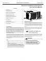
OWNER’S MANUAL Room Air Heat Pump with R-410A: RAH-183G Heat Controller, Inc. • 1900 Wellworth Ave. • Jackson, MI 49203 • (517)787-2100 • www.heatcontroller.com Heat Controller, Inc. Room Air Heat Pump with R-410A Contents Owner’s Manual Comfort ZoneTM Room Air Conditioner & Heat Pump Use and Care Manual Introduction. ............................................................. Introduction ..................................................................1 1 Safety Information................................................... Safety Information .......................................................1 1 Normal Care & Maintenance................................... Electrical Requirements ..............................................2 2 Normal Care and Maintenance ..................................2 3 Electrical Requirements.......................................... General Instructions ...................................................3. 5 Installation Requirements........................................ Installation Instructions ...............................................5 6 General Operating Instructions............................... OperatingInstructions............................................ Controls .................................................... 612 Installation Before Calling Service ..............................................1415 Vent Control. .......................................................... When Service Is Required ........................................1516 Troubleshooting. .................................................... Any Questions? .......................................................... 16 When Service is Required..................................... 15 Through-The-Wall Installation Instructions ............. 17 Any Questions....................................................... 15 Introduction Safety Information Be sure electrical service is adequate for chosen model of air conditioner. Complete electrical rating for unit is found on serial plate located behind front grille. Electrical outlet must be close enough to unit for power cord to reach without strain. Air conditioner should be the only appliance on individual circuit. Room air conditioners cool, dehumidify, and filter air inside dehumidify and Heatpump pumpmodels and electric both your home. Heat offer heat both models heating offer and coolheating cooling. Opening sections of manual ing. Theand opening sections of this manual providesprovide some general information room air conditioner models. The informationfor forallall room air conditioner models. Operating Operating Controls section describes operation of controls for each model. After After reading reading the the opening sections, turn to the Operating Controls section the panel layout Operating Controls section and and find find the panel layout that that matches your model. matches the model of your unit. For personal safety and to avoid possible damage to appliance or home, observe all safety instructions highlighted by symbol shown below. Read entire manual thoroughly before beginning installation and operation of your new room air conditioner. Be sure you have all necessary tools and materials on hand for the job. Study illustrations to familiarize yourself with important details of the installation process. Review manual for operating instructions. After installing unit, reread instructions to ensure each step is complete and that all parts are fastened in place. For best results and to minimize installation time, perform all procedures in the order shown. NOTE 1. Mechanical experience is required to install air conditioner. 2. Installation can take from 1 to 3 hours, depending on installer’s knowledge and skill. 3. If you you encounter encounter problems problemsduring duringinstallation, installation,call callour our 8617555. consumer information information line lineatat(86-756) (517) 787-2100 and ask for If your problem cannotdeparment. be resolvedIfby phone, contact an the technical service your problem cannot ® brand servicer. Contact andservicer. service authorized be resolvedGREE by phone, contact an authorized will be at your expense. 1 1 RECOGNIZE THIS SYMBOL AS A SAFETY PRECAUTION. WARNING To prevent preventheat heat related illness or death, do To related illness or death, do use this devicefor unattended. notnot use this device unattended cooling Failure of an or unattended air conditioner of persons animals unable to react to may result in extreme heatof in unattended area product failure. Failure air intended for cooling, causing heat related conditioner may result in extreme heat in illness or death of persons or animals. area intended for cooling, causing heatrelated illness or death of persons or animals. Room Air Heat Pump with R-410A Owner’s Manual WARNING WARNING To avoid death, personal injury or property damage due to electrical shock: HIGH TEMPERATURE STRESS HAZARD This room air conditioner is not meant to provide unattended cooling or life support for persons or animals that are unable to react to failure of the product. • • • • The failure of an unattended air conditioner may result in extreme heat in the conditioned space causing overheating or death of persons or animals. • • Precautions must be taken to ward off or guard against such an occurrence. • Unpacking Unpack and visually inspect the unit. Report any damage to Unpacking • the delivering carrier immediately. your Report unit is not damaged, Unpack and visually inspect theIfunit. any damage to remove and disgard all immediately. packing materials. On some the delivering carrier Remove andmodels discard all the air conditioner mountingthe kit air hardware may befront packing material.front On and/or some models conditioner packed mounting separately.kit hardware may be packed separately. and/or • • • • Record the and serial numbers of your unit in the space Record themodel model, serial and manufacturing numbers of your provided. information found on a nameplate visible afteron unit in theThis space providedisbelow. This information is found front of thevisible air conditioner has been The rated has athe nameplate after the front of removed. the air conditioner voltage, amperage and capacity for your specificand model can for been removed. The rated voltage, amperage capacity also be found on this nameplate. Read the warranty packaged your specific model can also be found on this nameplate. with the Register your unit with and keep the Keep warranty a Read theunit. warranty packaged the unit. theand warranty copy of your sales receipt for future reference. You may also and a copy of your sales receipt for future reference. You may want to record in the space provided the date purchased and also want to record in the space provided the date purchased the selling dealer. and the selling dealer. Grounding Instructions This appliance is equipped with a three-prong grounding plug for protection against possible shock hazards. If a two-prong wall receptacle is encountered, the customer is required to contact a qualified electrician and have the two-prong wall receptacle replaced with a properly grounded three-prong wall receptacle in accordance with the National Electrical Code. MODEL NUMBER SERIAL NUMBER Room air conditioners are designed to operate according to requirements on the nameplate and as shown in Table 1. Fuse or circuit breaker ratings must be according to the fuse instruction label and as shown in Table 1. Do not plug models marked “Use on Single Outlet Circuit Only” into a circuit with another appliance or light fixture. MANUFACTURING NUMBER Owner's Name Address State / Zip Receptacle Wiring Receptacle wiring must be of adequate size for unit. Refer to unit identification plate for exact power requirements. Minimum size of wiring, based on power requirements, is: / Date of Purchase Units up to 20 amps: 20–30 amp units: Authorized Dealer Address City ( State Observe all local codes and ordinances. Disconnect electrical power to unit before servicing. Ground appliance properly. Check with a qualified electrician if you are not sure this appliance is properly grounded. DO NOT ground to gas line. DO NOT ground to cold water pipe if pipe is interrupted by plastic, non-metallic gaskets, or other insulating (non-conducting) materials. DO NOT modify plug on power cord. If plug does not fit electrical outlet, have proper outlet installed by qualified electrician. DO NOT have a fuse in the neutral or ground circuit. A fuse in the neutral or ground circuit could result in an electrical shock. DO NOT use an extension cord with this appliance. DO NOT use an adapter plug with this appliance. DO NOT pinch power cord. DO NOT REMOVE warning tag from power cord. Electrical Requirements OWNER'S PRODUCT IDENTIFICATION City Heat Controller, Inc. 12 gauge 10 gauge LCDI or AFCI Power Cords Underwriters Laboratories (UL) and the National Electric Code (NEC) now require power cords that sense current leakage andbe can open the electrical circuit totothe leakage and able to open the electrical circuit theunit. unit. In In the the Zip ) Phone Number 2 2 Room Room Air Air Heat Heat Pump Pump with with R-410A R-410A Heat Heat Controller, Controller, Inc. Inc. Unit Unit Plug Plug Type Type Receptacle Receptacle Required Required Circuit Circuit Rating, Rating, Breaker, Breaker, Time Time Delay Delay Fuse Fuse Room Heat Pumps Voltage Voltage Rating Rating On On Nameplate Nameplate NEMA NEMA No. No. 5-15P 5-15P NEMA NEMA No. No. 5-15R 5-15R 125V-15AMP 125V-15AMP 115V 115V NEMA NEMA No. No. 6-15P 6-15P NEMA NEMA No. No. 6-15R 6-15R 250V-15AMP 250V-15AMP 230/208V 230/208V rated rated at at 12 12 amperes amperes or or less less NEMA NEMA No. No. 6-20P 6-20P NEMA NEMA No. No. 6-20R 6-20R 250V-20AMP 250V-20AMP 230/208V 230/208V rated rated over over 12 12 amperes, amperes, but not more but not more than than 16 16 amperes amperes NEMA NEMA No. No. 6-30P 6-30P NEMA NEMA No. No. 6-30R 6-30R 250V-30AMP 250V-30AMP 208V 208V rated rated over over 16 16 amperes, amperes, but but not not more more than than 24 24 amperes amperes Owner’s Owner’s Manual Manual Heat Heatpumps pumpswork workby bymoving movingheat heatinstead insteadof ofcreating creatingit. it. In Inthe the summer, the cool indoor coil absorbs heat from your room summer, the cool indoor coil absorbs heat from your room and and moves moves itit outdoors, outdoors, providing providing cooling. cooling. In In the the winter, winter, heat heat pumps pumps reverse reverse this this operation. operation. By By lowering lowering the the temperature temperature of of the the outdoor outdoor coil coil below below the the outdoor outdoor temperature, temperature, the the heat heat pump pump absorbs absorbs the the heat heat from from outdoors outdoors and and moves moves itit inside inside your your house. house. This This heat heat transferring transferring process process is is very very efficient. efficient. For For example, example, at at 45°F 45°F outdoor outdoor temperature, temperature, aa heat heat pump pump can can provide provide 22 ½ ½ watts watts of of heat heat for for every every watt watt of of electricity electricity itit consumes. consumes. As As outdoor outdoor temperatures temperatures drop, drop, the the heating heating capacity capacity and and efficiency efficiency of of the the heat heat pump pump declines. declines. At At temperatures temperatures below below 45°F, 45°F, itit is is likely likely that that ice ice will will form form on on the the outdoor outdoor coil. coil. Heat Heat pump pump units units are are designed designed to to operate operate as as aa heat heat pump pump above above approximately approximately 40°F. 40°F. Below Below 40°F, 40°F, these these units units switch switch autoautomatically matically from from reverse reverse cycle cycle heat heat pump pump to to auxiliary auxiliary electric electric heating. heating. No No defrost defrost is is required. required. There There is is no no minimum minimum operating operatingtemperature. temperature. event, event, the the unit unit does does not not operate, operate, check check the the reset reset button button located located on on or or near near the the head head of of the the power power cord cord as as part part of of the the normal troubleshooting procedure. normal troubleshooting procedure. Use Usecopper copperwire wireonly. only.Consumer’s Consumer’sresponsibility responsibilityis isto toprovide provide proper proper and and adequate adequate receptacle receptacle wiring wiring that that conforms conforms to to all all applicable applicable codes. codes. All All wiring wiring should should be be installed installed by by qualified qualified electrician. electrician. Normal Care and Maintenance WARNING To avoid property damage, personal injury To damage, personal injury Toavoid avoidproperty property damage, personal injury To avoid property damage, personal injury or shock, turn unit or death due electrical shock, turn or death due toto electrical shock, turn unitfan ordeath deathdue dueto toelectrical electrical shock, turn fan OFF and remove from wall before control and remove from OFF andOFF remove plug fromplug wall outlet outlet before control OFF andplug remove plug from wall wall inspecting unit or inspecting unitinspecting or performing performing maintenance. outlet unit or outlet before before inspecting unitmaintenance. or performing performing Installation Complete Completestep-by-step step-by-stepinstallation installationinstructions instructionsare arefurnished furnished with your unit. These instructions will be found on with your unit. These instructions will be found on aa separate separate page page included included with with this this manual manual or or in in the the mounting mounting kit kit assembly. assembly. Follow Follow these these instructions instructions carefully. carefully. Keep Keep these these instructions instructions with with this this manual manual for for future future reference. reference. Your Your unit unit will will be be one one of of the the following following three three designs: designs: •• Unit Unit with with aa window window mounting mounting kit kit These models are designed for These models are designed for mounting mounting though though an an opening opening in in aa wall. wall. These These units units can can be be adapted adapted to to window windowinstallation installationby byusing usingthe theoptional optionalwindow windowmountmounting ing kit kit supplied supplied with with your your unit. unit. •• Unit without a window Unit without a window mounting mounting kit kit No No window window mounting mounting kit kit is is supplied supplied with with the the unit. unit. These These models models are are designed designed for for mounting mounting through through an an opening opening in in aa wall. wall. These These units units can can be be adapted adapted to to window window installation installation by by purchasing purchasing an an optional optional window window mounting mountingkit. kit. Consult Consultyour yourdealer dealerto tochoose choosethe thekit kitthat that is is appropriate appropriate for for your your model model and and installation. installation. •• Unit Unit with with aa separate separate sleeve sleeve Some Builder Some Buildermodels modelsare aredesigned designedsuch suchthat thatthe theouter outer case case and and the the chassis chassis can can be be purchased purchased separately. separately. Through-the-wall Through-the-wallinstallation installationinstructions instructionsare areincluded included with with the the outer outer case. case. These These models models can can be be adapted adapted to to window window installation installation by by purchasing purchasing an an optional optional mountmounting ing kit. kit. maintenance. maintenance. Annual Annual Inspection Inspection ItIt is is suggested suggested that that your your unit unit be be inspected inspected by by your your dealer dealer or or servicer servicer once once aa year. year. ItIt is is advisable advisable to to have have the the outer outer case case removed removed and and the the unit unit thoroughly thoroughly cleaned. cleaned. Note: of may greatly reduced live aa Note: The The life life of your your unit unit may be bebe greatly reduced ifif you you live in in Note: life unit greatly ifif you live Note: The The life of of your yoursuch unit may may be greatly reduced reduced you live corrosive environment as an oceanside location with salty corrosive environment such as an oceanside location with salty in corrosive type environment. Under these in aa salt salt air air or or other other corrosive type environment. Under these air. conditions, the unit should removed from its air. Under Under these these conditions, thebe unit should be be removed fromand its conditions, the unit should removed from its case conditions, the unit should be removed from its case and case and completely cleaned at least once a year. At that time case and completely cleaned at least once a year. At that time completely cleaned at once aa year. At time completely cleaned at least least once year. At that thatshould time any any any or on the painted surfaces any scratches scratches or blisters blisters on the paintedsurfaces surfaces should should be be scratches or blisters on the painted be scratches or blisters on the painted surfaces should be sanded and repainted. Placing an algaecide tablet in the outdoor sanded and repainted. Placing an algaecide tablet in the outdoor sanded and repainted. Placing an algaecide tablet in the sanded and repainted. an algaecide tabletwhere in the side of unit’s basepan is in side of the the unit’s basepan Placing is suggested suggested in humid humid areas areas where outdoor side the unit’s outdoor side of of the unit’s basepan basepan is is suggested suggested in in humid humid algae formation is algae formation is common. common. areas areaswhere wherealgae algaeformation formationis iscommon. common. 33 33 Owner’s Manual Room Air Heat Pump with R-410A Front Grille and Filter Removal The front contains a removable grille that provides easy access to the air filter. To clean the filter use one of the following methods for filter removal: Heat Controller, Inc. Optional Air Filter Installation Remove air filter from plastic bag. Insert three tabs on right side of filter into three slots on filter frame. Carefully bow middle of filter until two tabs on filter can be inserted into two slots on filter frame. Relax bow. METHOD ONE Grasp filter handle and slide filter out of unit. Reinstall air filter and grille by reversing removal procedure. Front Grille and Cabinet Cleaning Grille and cabinet may be cleaned with warm water and mild soap or detergent. Cleaning and polishing compounds are not recommended, as they may damage plastic surfaces. Air Filter Cleaning A dirty air filter reduces operating efficiency of unit. Filter should be inspected at least once every week during operation. Clean filter with vacuum cleaner or wash in warm water and mild detergent. Filter should be thoroughly dried before replacing in unit. Do not operate unit without filter in place. Fan Motor Care The fan motor is permanently lubricated for long life. There is no need to oil the motor. Slide-out Chassis Removal from Outer Case 1. Remove front grille by sliding grille to left and pulling out. 2. Remove air filter by sliding to left. 3. Remove four screws holding plastic front to unit and remove front. 4. If the unit has a screw holding the basepan clip to the chassis, remove the screw. CAUTION To personal injury, be be To reduce reducethe therisk riskofof personal injury sure to have sufficient help when moving sure to have sufficient help when moving your airair conditioner cancan be your unit. unit.AAroom room conditioner excessivley heavy. weigh between 70 and 240 pounds. 5. Using basepan handle, pull chassis straight out, slowly and evenly, until approximately 9-12 inches extends 4 4 Room Air Heat Pump with R-410A Heat Controller, Inc. from outer case. Use both hands to grasp basepan and pull remaining chassis from outer case. PLASTIC FRONT BASEPAN CLIP Owner’s Manual Drain Cup Installation and Use (on some models) Your air conditioner uses a system where the water removed from the indoor air (condensate) is channeled to the outdoor side of the unit. The outdoor fan blade has a “slinger” ring attached to it that dips into the water and slings the water onto the outdoor coil surface. This is the sound of water you hear during normal operation. The water quickly evaporates on this warm surface and improves the efficiency of your air conditioner. In normal conditions the unit can evaporate the water as fast as it is removed from the indoor air. However, in very humid conditions excess amounts of water may drip off the unit chassis. If this proves to be a problem, install the condensate drain cup included with the unit to route excess water where it would not be a problem (see illustration below). To install, remove the unit chassis from the outer case. Insert the condensate drain cup through the recessed ½” hole on the right side bottom flange of the outer case. Once inserted, place a ½” diameter hose or tube on the drain cup bottom spout. The hose allows you to route where you want the excess water to go. Reinsert the unit chassis into the outer case. The unit basepan overflow hole will be positioned directly above the drain cup and will catch any water that might run out. CHASSIS NOTE: Basepan clip is shipped in plastic bag with mounting screw and condensate drain cup. Install clip after reinserting chassis into outer case to prevent accidental chassis removal. General Operating Instructions While operation of all units is similar, controls vary slightly from model to model. Operating Controls section shows control panel of unit purchased and gives detailed information about operation of controls. Initial Start-Up and Cooling Select the highest fan speed and set temperature control to its coldest position. When the desired temperature is reached, slowly move the temperature control toward a warmer setting until the compressor shuts off. The thermostat will then cycle the compressor on and off to maintain this selected temperature. Adjust the fan speed for desired air circulation. Outer Case Condensate Drain Cup BAFFLES 1/2" Diameter Hose Switchover Thermostat Control Emergency heat switch overrides heat pump (compressor) and starts auxiliary electrical heater. When switch is ON, heat pump is locked out. OUTDOOR LOUVERS INDOOR GRILLE • Changing Airflow Direction Baffles Airflow on unit may be diverted left or right from center by baffles. Upward and downward air discharge is provided by tilting louvers. Adjust baffles and tilt louvers for desired airflow pattern. Use emergency switch only when heat pump fails to provide adequate heat. Cause of heat pump malfunction should be determined by authorized servicer. Cost of operating unit will increase when emergency heat switch is engaged. To access and engage emergency switch: 1. Remove front grille, air filter, and plastic front, as described in Installation Instructions. 2. Remove basepan clip. 3. Slide chassis out of case about two inches. 4. Locate access hole for emergency switch above label on right front of control box. 5. To start emergency heat, insert flathead screwdriver into slot and turn counterclockwise until switch-stop is reached. Airflow Around Unit Check the indoor grille and outdoor louvers for obstructions to airflow. Do not block the airflow to and from the unit. If air is obstructed and/or deflected back into the unit, the air conditioner’s compressor may cycle on and off rapidly. This could damage your unit. 6. Return chassis to case. 7. Replace basepan clip, plastic front, air filter, and front grille. 5 5 IMPORTANT — Save these ● of this air conditioner. Aluminum house wiring may present special problem s —consult a qualified electrician. instructions for local inspector's use. IMPORTANT — Observe all ● Owner’s Manualgoverning codes and ordinances. Room Air Heat Pump with R-410A ● Installation Ins tructions ● ● ● ● ● ● Heat Controller, Inc. Note to Installer — Be sure to leave these instructions with the Consum er. TOOLS YOU WILL NEED Note to Consumer — Keep these instructions for future reference. Skill level — Installation of this appliance requires basic mechanical skills. Adjustable wrench Completion time — Approximately 1 hour We recommend that two people install this product. 517-787-2100 Question? Consumer line (86-756) 8617555(Customer Service Center) Proper installation is theinformation responsibility Phillips head screwdriver Flat-blade screwdriver of the installer. Product failure due to improper installation is notBEFORE covered under the BEGIN Warranty. YOU CAUTION: Air Conditioner Installation Ins tructions Air Conditioner Do not, under any circum stances, cut or Pencil Ruler orfrom tape mthe easure remove the third (ground) prong Read thes e ins tructions com pletely ELECTRICAL REQUIREMENTS power cord. and carefully. Do not change the plug on the power cord of this air conditioner. IMPORTANT these The 3-prong grounding— Save plug minimizes the Question? Consumer information line (86-756) 8617555(Customer Service Center) instructions for local inspector's use. AluminumLevel house wiring may present possibility of electric shock hazard. If the wall Scissors special or knife problem s —consult a qualified electrician. outlet you plan to use is only a 2-prong outlet, IMPORTANT — Observe all it is your responsibility have it replaced with governing codes and toordinances. a properly groundedYOU 3-prong wall outlet. BEFORE BEGIN CAUTION: Note to Installer — Be sure to leave these Power cord includes a current interrupter Some models require 230/208-volt a.c., instructions with the Consum er. TOOLS YOU WILL NEED Do not,Aunder anyreset circum stances, cut oron device. test and button is provided protected with a time delay fuse or circuit remove prong Notethes to Consumer — Keep these the plug the case.third The (ground) device should be from testedthe on a Read e ins tructions comshould pletelybe installed breaker. These models power instructions forown future reference. periodiccord. basis by first pressing the TEST button and carefully. on their single branch circuit for Do the plug on If thethepower Skill level — Installationand of this appliance and not thenchange the RESET button. TESTcord button best performance to prevent of this requires basic mechanical wrench IMPORTANT — Save these wiring overloading house orskills. apartment does notair tripconditioner. or ifAdjustable the RESET button will not stay instructions for local use.a possible circuits, which could cause engaged, discontinue use may of thepresent air conditioner Aluminum house wiring special Completion time — inspector's Approximately 1 hour fire hazard from overheating wires. problem s —consult a service qualified electrician. and contact a qualified technician. We recommend that — Observe two people all install IMPORTANT this product. governing codes and ordinances. Proper responsibility Note toinstallation Installer — is Bethe sure to leave these Phillips head screwdriver Flat-blade screwdriver of the installer. instructions with the Consum er. TOOLS YOU WILL NEED Product failure due— toKeep improper Note to Consumer theseinstallation is not covered Warranty. instructions forunder futurethe reference. ● ● ● ● ● ● ● ● ● ● ● ● ● Skill level — Installation of this appliance requires basic mechanical skills. ELECTRICAL REQUIREMENTS Completion time — Approximately 1 hour We recommend that two people install this product. The 3-prong grounding plug minimizes the Proper installation the responsibility possibility of electricis shock hazard. If the wall of the outlet youinstaller. plan to use is only a 2-prong outlet, it is your responsibility to have itinstallation replaced with Product failure due to improper a properly grounded 3-prong wall outlet. is not covered under the Warranty. ● Pencil Adjustable wrench Ruler or tape m easure ● ● 6 ● Level Phillips head screwdriver Scissors or knife Flat-blade screwdiver screwdriver Flat-head ● Power cord includes a current interrupter device. A test and reset button is provided on Pencil Ruler or tape m easure the plug case. The device should be tested on a periodic basis by first pressing the TEST button and then the RESET button. If the TEST button does not trip or if the RESET button will not stay engaged, discontinue use of theScissors air conditioner Level or knife and contact a qualified service technician. Some models require 230/208-volt a.c., protected with a time delay fuse or circuit breaker. These models should be installed ELECTRICAL REQUIREMENTS on their own single branch circuit for best performance and to prevent overloading houseplug or apartment wiring The 3-prong grounding minimizes the circuits, which shock could cause a possible possibility of electric hazard. If the wall fire plan hazard wires.outlet, outlet you to from use isoverheating only a 2-prong it is your responsibility to have it replaced with a properly grounded 3-prong wall outlet. Some models require 230/208-volt a.c., protected with a time delay fuse or circuit breaker. These models should be installed on their own single branch circuit for best performance and to prevent overloading house or apartment wiring circuits, which could cause a possible fire hazard from overheating wires. 6 6 Power cord includes a current interrupter device. A test and reset button is provided on the plug case. The device should be tested on a periodic basis by first pressing the TEST button and then the RESET button. If the TEST button does not trip or if the RESET button will not stay engaged, discontinue use of the air conditioner and contact a qualified service technician. Room Air Heat Pump with R-410A Heat Controller, Inc. Owner’s Manual Installation Instructions PARTS INCLUDED Window sash seal (A ppearance m ay vary) Left accordion panel Top mounting rail Foam top window gasket Right accordion panel V-support (2) Window locking bracket (2) Type A (6) Bolt (2) & nuts (2) Type B (4) Type D (6) Type C (7) 7 7 Type E ((4) Type F (2) Room Air Heat Pump with R-410A Owner’s Manual Heat Controller, Inc. Installation Instructions 1 WINDOW REQUIREMENTS ● ● 3 REMOVE THE AIR CONDITIONER FROM THE CASE These instructions are for a standard double-hung window. You will need to modify them for other types of windows. T he air conditioner can be ins talled without the accordion panels if needed to fit in a narrow window. See the window opening dim ens ions . All supporting parts must be secured to firm wood, m as onry or m etal. T he electrical outlet m us t be within reach of the power cord. Remove the screw andand locking thelocking locking screw lockA Remove bracket from the lower frame. Save to ing bracket from the lower frame. reinstall later. Save to reinstall later. Remove the save the ground ground screw screw.and Save toto B Remove reinstall later. reinstall later. ● ● 173/8" min. Remove the ground screw and save to reinstall later 30" to 38.1" (With accordion panels) 26” min. (Without accordion panels) Slide the air conditioner from the case by C gripping the base pan handle and pulling unit forward while bracing the case. 26" min. (Without accordion panels) 2 STORM WINDOW REQUIREMENTS A s torm window fram e will not allow the air conditioner to tilt toward the outs ide, and will keep it from draining properly. To adjus t for this , attach a piece of wood to the s tool. WOOD PIECESWIDT H: 2" LENGTH: Long enough to fit inside the window frame. THICKNESS : To determine the thickness, place a piece of wood on the stool to make it 1/2" higher than the top of the s torm window fram e. A ttach s ecurely with nails or s crews provided by the ins taller. 1/2" higher than fram e 4 PREPARE THE WINDOW Cut the window sash seal to the proper length. Peel off the backing and attach the seal to the underside of the window sash. W ood Stool Storm window fram e 8 8 Room Air Heat Pump with R-410A Heat Controller, Inc. Owner’s Manual Installation Instructions 6 INSTALL THE CASE 5 PREPARE THE CASE IN THE WINDOW A Install the top mounting rail with 4 type B screws from the inside of the case. A Carefully slide the case into the window and center the case. Lower the window behind the top mounting rail. Pull the bottom of the case forward so that the bottom mounting rail is tight against the back of the window stool. Mount the case to the window sill using 4 type E screws. Drill pilot holes, if necessary. B Insert the frames for the accordion panels into the top mounting rail and the bottom frame guides. Attach the accordion panels to the side of the case using 3 type A screws on each side. Note: When attaching the accordion panels, make sure to only screw the inner panels to the case sides. Top mounting rail 4 type E screws S tool B Make sure the bolts and nuts are all of the way in both the left and right V-supports. Bottom frame guides Bolt and nut C Position the V-supports on the case bottom so that they will be near the outside wall. Attach a V-support to each side of the bottom of the case using type C screws, 3 on each side. V-support 9 9 Room Air Heat Pump with R-410A Owner’s Manual Heat Controller, Inc. Ins tallation Ins tructions BRACKETS 7 INSTALL INSTALLSUPPORT SUPPORT BRACKETS 6 INSTALL THE CASE AND FOAM GASKET ANDTOP THEWINDOW FOAM TOP WINDOW IN THE WINDOW (cont.) GA S K E T D Adjust the leveling bolts and nuts against the outside wall so that the case has a slight tilt to the outside. Tighten nuts with an adjustable wrench. Use a level; about a 1/2 bubble will be the correct case slant to the outside. ttach the s upport brackets with two A A type D s crews , one on each s ide. Cutthe thetop foam top foam window to the window gasketgas to ket the window B Cut window width. width. Stuffthe thefoam foam between the glas s and the between the glass and the window C Stuff window to prevent air and ins ects from to prevent air from getting into the room. getting into the room . E Use a wood block (obtained locally) between the leveling bolts and the wall if the wall is weak or if the weight of the air conditioner falls between the studs in the wall. F Extend the left and right accordion panels to the vertical window sashes. Drill pilot holes and attach the top and bottom corners with 4 type D screws. Top mounting rail Type D screw Type D screw Type D screw Type D screw 10 10 Heat Controller, Inc. Room Air Heat Pump with R-410A Owner’s Manual Ins tallation Ins tructions 8 INS INSTALL CONDITIONER TALLTHE THEAIR AIR CONDITIONER 8 INSTALL THE AIR CONDITIONER A Slide the air conditioner into the case. Do not push on the controls or the finned coils. Make sure the air conditioner is firmly seated. G Pull the coiled power cord from its shipped IN THE IN THECASE CASE IN THE CASE CASE(cont.) (cont.) position in the air discharge area. Attach the front grille frame to the case by inserting the tabs on the grille frame into the slots on the front top of the case. Push the grille frame in. And install the 2 type F screws at bottom left and right side of front panel. B Reinstall the locking bracket and screw removed earlier. Guide the lever carefully through the grille fram e as you pus h it in. C Reconnect the ground wire to the air conditioner using the screw removed earlier. IMPORTANT: The ground wire must be reinstalled to ensure a proper ground. H Secure the front grille frame to the case with one type C screw. the front grille from its box and D Remove remove the shipping tape. I Reinstall the filter. the inlet grille at the bottom corners E Grasp and pull it forward. Unhook it from its top hinges and set it aside. J Reinstall the inlet grille. Connect power. Using the tab, pull up slightly on the filter F to release it and pull it down and out. 11 11 Room Air Heat Pump with R-410A Owner’s Manual Room Air Heat Pump with R-410A Owner’s Manual Operating Controls(For Electronic units) Operating your air conditioner properly helps you to obtain the best possible results. For Electronic units Electronic units This section explains proper For air conditioner operation. Operating your air conditioner properly helps you to obtain the IMPORTANT: best possible results. Operating your air conditioner properly helps you to obtain the ■ If you turn off the air conditioner, wait at least 3 units minutes For Electronic best possible results. This section proper conditioner operation. before turningexplains it back on. Thisair prevents the air conditioner IMPORTANT: This sectionfrom explains proper air or conditioner blowing a fuse tripping aoperation. circuit breaker. Operating your air conditioner properly helps you to obtain the ■ If you turn off the air conditioner, wait at least 3 minutes IMPORTANT: Do not try to operate your air conditioner thecooling cooling mode when ■ possible Do notbefore operate your air conditioner inin the mode best results. turning it back on. This prevents the air conditioner For Electronic units ■ If you offfrom the air conditioner, wait at least 3 minutes outside temperature is below 61°F (16°C). Do not try to when outside temperature is below 61°F (16°C). Do not try to This turn section explains proper air conditioner operation. blowing a fuse or tripping a circuit breaker. operate before turning backairon. This prevents the air conditioner your airitconditioner in the heating mode when outside temperature operate your conditioner in the heating mode when outside IMPORTANT: not try operate your airthe conditioner inthe the cooling mode when ■ Do not to conditioner operate your air conditioner in mode Operating your air properly helps evaporator you tocooling obtain the from blowing a86°F fuse or tripping a circuit breaker. is overDo (30°C). Otherwise, inside coil will freeze temperature is over 86°F (30°C). The inside evaporator coil ■ Ifbest you turn offoutside the airtemperature conditioner, wait least 3Do minutes outside temperature is will below 61°Fat61°F (16°C). not operate possible results. when isoperate below (16°C). Dotry nottotry to up, and the air conditioner properly. will freeze up, and the air conditioner will operate properly. ■ Do notbefore try to operate air conditioner inthe theheating cooling mode turning ityour back This prevents the air conditioner your airexplains conditioner in the heating mode when outside temperature operate your airon. conditioner in mode when outside This section proper air conditioner operation. from blowing fuse(30°C). or tripping a circuit breaker. is over a 86°F Otherwise, the inside evaporator coil when outside temperature below 61°F (16°C). Do not try to temperature isisa over 86°F (30°C). The inside evaporator coilwill freeze IMPORTANT: NOTE: Inup, theand event of power failure, your air conditioner will theup, airand conditioner willmode operate properly. operate air conditioner in the heating when outside will freeze the air conditioner will operate properly. ■operate Doyour not at try to operate your air conditioner in the cooling mode the previous settings whenwait the at power is restored. ■ If you turn off the air conditioner, least 3 minutes temperature is over 86°F (30°C). The inside evaporator coil whenbefore outside temperature is below 61°F (16°C). Doair not try to it back This prevents the conditioner NOTE: Inturning theair event of aon. power failure, your air conditioner will will freeze up, and the conditioner will operate properly. operate your air conditioner heatinga mode outside from blowing a fuse in orthe tripping circuitwhen breaker. Operating Controls( Operating Controls( ) ) Operating Controls( ) Operating Controls( ) operate at the previous settings when the power is restored. temperature is over 86°F (30°C). The inside evaporator coil ■ event Do not to operate your air conditioner the cooling NOTE: In the oftry aand power failure, your airoperate conditioner will mode will freeze up, the air conditioner will properly. Lights next to the touch pads on61°F thein(16°C). air conditioner outside temperature is below Do not try to operate at the when previous settings when the power is restored. when Heat/Cool/Energy Saver mode. is in the temperature or Lights next to in the touchshows pads on the air conditioner The display thethe setdelay temperature time Set mode. NOTE: the event of a on power failure, yourdelay airLight conditioner indicates the will unit ShowsIn time remaining timer. when inthe Heat/Cool/Energy Saver is in the temperature or control panel indicate the selected settings. Lights next touch pads on the airthe conditioner operate at the previous settings when power is restored. Shows theto room temperature when inmode. delay time Set mode. Fanshows Only mode control panel the selected The display theindicate setroom temperature Shows the temperature whensettings. in indicates the unit Light indicates Light the unit Fan Only mode when inThe Heat/Cool/Energy Saver mode. is in theortemperature or istemperature in the temperature display shows the set indicates the unit POWER Light indicates the unit time Set Lights next tothe thedelay touch pads onisLight the airmode. conditioner Shows when time remaining on timer. delay time Set delay mode. in Heat/Cool/Energy Saver in theortemperature or Set is inmode. the temperature POWER Shows Shows thecontrol room when in delay time Set mode. timetemperature remaining on the delay timer. delay time Set mode. + TEMP/TIMER panel indicate the selected settings. Set AUTO HEAT Fan Only modethe room temperature when in Shows TEMP/TIMER + + - -- HIGH + COOL HEAT Themode display shows AUTO the set temperature Fan Only MED HIGH ENERGY SAVERLight indicates the unit COOL when in Heat/Cool/Energy Saver mode. is in the temperature or POWER FAN ONLY LOW MED ENERGY SAVER delay time Set mode. ShowsPOWER time remaining on the delay timer. Set FAN ONLY LOW TIMER FANtemperature TEMP/TIMER Shows the room when in Set MODE SWING 1-24 HR AUTO SPEEDHEAT TIMER FAN TEMP/TIMER MODE SWING FanHIGH Only mode 1-24 HR AUTO SPEED COOLHEAT MED HIGH LOW MED POWER COOL ENERGY SAVER ENERGY SAVER FAN ONLY MODE SWING SWING is on. delay timer is .5-24 HR 0.5 TIMER TIMER 1-24 HR MODE 1-24 HR Air Air Conditioner Controls Conditioner Controls SPEED AUTO HIGH HEATSWING .5-24 HR COOL MED ENERGY SAVER LOW FAN ONLY set. - FAN SPEEDFAN Light indicates Light indicates the Set Light indicates delay Light indicates SWING is on. timer is set. the TIMER TIMER TEMP/TIMER FAN ONLY LOW indicates the the Light indicatesLightLight indicates TIMER FAN timer is set. MODE SWING is on. delaydelay timer is set. 1-24 HR SPEED SWING Air Conditioner Controls Air Conditioner Controls Air Conditioner Controls Light indicates Light indicates the Delay 1–24hr Delay timer Increase Delay timer Decrease Swing Mode select Delay 1–24hr Delay timer Fan speed Delay 0.5–24hr Delay timer Decrease Decrease Decrease Temperature Mode select Delay timer set Increase Mode select Decrease Decrease Fanand speed Decrease Mode select Fan speed DecreaseTemperature set FanIncrease speed Temperature and Decrease Decrease set Increase and Decrease Temperature set Increase and Decrease Delay timer Increase Fan speed Increase Swing Delay timer Increase Swing Auto FanUnit on power on/off Auto Fan on Fan speed Increase Fan on Fan speedAuto Increase Unit power on/off speed Increase Remote Control Unit powerFanon/off Unit power on/off Remote Control Remote Control Remote Control Power Pad Controls Controls Turns air conditioner on and off. Power Pad Power Turns Pad air conditioner on and off. Controls Turns air conditioner on and off. Display Power Pad Shows the set temperature when in Heat/ Controls Turns air conditioner on andmode. off. Shows time Cool/Energy Saver Display remaining on the delay timer. Shows Shows the set temperature when in Heat/ Display the room temperature when in Fan Only Power Pad Cool/Energy Saver mode. Shows time Shows the setconditioner temperature when in Heat/ modes. Theon Setthe light willoff. turn on while Turns air ondelay and remaining timer. Shows Cool/Energy mode. when Showsintime Display setting. the roomSaver temperature Fan Only remaining timer. Shows the set on temperature in Heat/ modes. Thethe Set delay lightwhen will turn onShows while the room temperature when in Fan Cool/Energy Saver mode. Shows timeOnly setting. Temp Increase ▲ /Decrease ▼ Pads remaining timer. Shows modes. The on Set the lightdelay will turn on while Display Use to set temperature when in Heat the room temperature when in Fan Only setting. Shows the set temperature when in Heat/ Low, Med or High. Use the Auto pad to Mode Pad Use turn to TIMER setAuto thePads air conditioner to Cool, fan Use to TIMER set the airon. conditioner to Cool, Timer/Delay Pads Energy Saver,Fan OnlyPads or Heat (on some Energy Saver,Fan Only or Heat (on some is off, it TIEMR ON—When the air conditioner models) mode. Mode PadON—When Timer/Delay On—When the airon conditioner TIEMR the aircome conditioner models) mode. can be set to automatically in 0.5istooff, 24isitoff, it Usecan to be set set theto airautomatically conditioner to Cool,on in 0.5 to 24 come hours at its previous mode and fan settings. TIMER PadsSaver,Fan Energy Only ormode Heat (on some hours at its previous and fan settings. TIMER Pads models) mode. the air conditioner is off, it TIEMR ON—When SWING Pad TIEMR ON—When the aircome conditioner istooff, can be set to automatically on in 0.5side-to-side 24it SWING Turn on Pad to provide continuous TIMER Pads can be set to automatically come on in 0.5side-to-side to hours atair itscirculation. previous fanside-to-side settings. Forand fixed air24 Turn on tomode provide continuous Auto Fan on Delay timer Increase Delay 1–24hr Controls Delay Timer Increase (+) /Decrease (Æ-)delay + / Decrease –Pads pads on the unit or�the Increase Use to set temperature when in will Heat(on some pads on the remote control set�the Delay Timer Increase � (+) /Decrease �the(Æ-)delay Pads pads on the remote control will set models)/Cool/Energy Saver mode. The Set light timer . time when using the Delay 1–24hr timer 0.5-24hr time using the turn Delay 1–24hr timer .5-24hr timer turnwhen onthe while setting. Eachwill touch of Increase � / on Decrease �( ). The Set light will while setting. Each touch the Increase � / on Decrease � – The Set light willIncrease turn setting. +while / Decrease pads on theof unit or the + / Decrease – � (Æ-) Pads pads on the unit orIncrease thecontrol Increase �will (+) /Decrease padsDelay onFan theTimer remote set the delay Speedcontrol Pads will set the delay pads onFan the Speed remote Pads time when using the Delay 1–24hr timer ( ). time when using thethe Delay 1–24hr timer ( ).Med, High Use toset set fan speed Low, touch ofthe the Increase � /to Decrease TheEach SetUse light will turn on while setting. towill fan speed to Low, Med, � High The Set light turn on while setting. or Auto on the unit. NOTE: On remote + / Decrease – pads on the unit or the Increase or Auto on the unit. NOTE: On thethe remote +/ control, usethe thefan fan speed pads on theuse remote control willIncrease setIncrease the delay control, speed + / Fan Speed Speed Pads – pads to set the fan speeds to Fan Pads Decrease time when using theto Delay 1–24hr ( to). – pads set the fantimer speeds Decrease Use to toset set the fan speed to Low, Med, High The Set light will turn on while setting. Low, Med or High. Use the Auto pad Use the fan speed toUse Low, Med, High Low, Med or High. the Auto pad to to Autoturn onthe the unit. NOTE: remote or Auto on unit. NOTE: thethe remote turn Auto fan on.OnOn Auto fan on. control, fan Increase + /+ / control, usethe thePads fanspeed speed Increase Fan use Speed – pads to set the fan speeds to Decrease – pads to set the fan speeds Decrease UseMode to setPad the fan speed to Low, Med,to High Mode PadUse Low, Med or High. the Auto pad to to Low,or Med or High. Use the Auto pad Auto on the unit. NOTE: On the remote Use to set the air conditioner to Cool, Use to set the air conditioner to COOL, ENERGY Use to set the air conditioner to Cool, Use to set the air conditioner to COOL, ENERGY turn Auto fan on. turncontrol, Auto fan on. + / use the fan speed Increase Energy Saver,Fan Only or Heat (on some SAVER, FAN ONLY or HEAT mode Energy Saver,Fan Only or Heat (on SAVER, FAN ONLY or HEAT mode some Decrease pads to set the fan speeds to models) models)–mode. mode. Mode Pad - + Heat Controller, Inc. modes. The light models)/Cool/Energy will turn on while (onSet some Saver Cool/Energy Saver mode. Shows time setting. The Set light will turn on while setting. remaining on the delay timer. Shows the room when in Fan Only Presstemperature Increase(+) and Decrease (-) Pads modes. The Set light will turn on while Temp Increase � /Decrease � Pads at the same time for 3 seconds,Temperature setting. Use to set set temperature temperature when in Heat(on Use when in Heat/Cool/Energy display will change between ∞oÑF some and oC. models)/Cool/Energy Saver mode. The Set light Saver. The SET light will turn on while setting. Temp Increase � /Decrease � Pads will turn on while setting. Use toIncrease set temperature when in Heat(on some � (Æ-) Pads Delay Timer Increase (+) /Decrease Timer/Delay Temp � /Decrease �� Pads models)/Cool/Energy Saver mode. Set light Use to set temperature when in Heat(on some Delay Timer Increase � (+)The /Decrease � (Æ-) Pads will turnEach on while setting. models)/Cool/Energy Saver mode. The Set light touch of the Increase � / Decrease � will turn onIncrease while setting. Each touch ofunit Increase � Decrease � Temp �the /Decrease �/ Pads + / Decrease – pads on the or the Increase your the heating mode when NOTE: Inoperate the event of air a power failure, your air conditioner willoutside control panel indicate theinselected settings. Lights next toconditioner the touch pads on the airrestored. conditioner operate at the previous settings when the temperature is over 86°F (30°C). Thepower inside is evaporator coil Thewilldisplay the setairtemperature control panel indicate the selected freezeshows up, and the conditioner will operate properly. Lightsettings. indicates the unit Shows time remaining on the delay timer. Heat Controller, Inc. 12 12 12 12 12 12 12 hours atdirection,turn itsON—When previous mode and fandesired settings. TIEMR theFor air conditioner is off, on until the air it air air circulation. fixed side-to-side SWING Pad candirection be set to automatically come on in 0.5 24 is obtained,then turn it off. direction,turn on until the desiredtoair Turn onPad toatprovide continuous side-to-side SWING hours its previous mode and fan turn settings. direction is obtained,then it off. air circulation. For fixed side-to-side air Turn on to provide continuous side-to-side direction,turn on until the desired air SWING Pad air circulation. For fixed side-to-side air direction turn it off. Turn is onobtained,then to provide side-to-side direction,turn on untilcontinuous the desired air air circulation. For fixed side-to-side air direction is obtained,then turn it off. direction,turn on until the desired air direction is obtained,then turn it off. Room Air Heat Pump with R-410A Heat Controller, Inc. Owner’s Manual Timer/Delay OFF—the When air conditioner TIMER OFF—When airthe conditioner is on,is on, Cooling Descriptions it can be set to automatically turn off in 0.5 to 24 hours. For Normal Cooling—Select the Cool mode and High or Med fan with a middle set temperature. How to set: For Maximum Cooling—Select the Cool mode and High fan with a lower set temperature. Press the TIMER TIMER 0.5 1–24hr -24hr pad on the unit or the pad on the remote control. Each touch of the Increase � / Decrease � pads on the unit or the Increase + / Decrease – pads on the remote control will set the timer in 0.5 hour or 1 hour intervals (the intervals is 0.5 hour as the delay timer below 10 hours; the intervals is 1 hour as the delay timer above 10 hours ). The Set light will turn on while setting. To review the remaining time on the TIMER -24hrtimer, timer,press press the the TIMER -24hr pad 1–24hr TIMER0.5 1–24hr padon onthe the 0.5 unit or the pad on the remote control. Use the Increase � / Decrease � pads on the unit or the Increase + / Decrease – pads on the remote control to set a new time if desired. To cancel the timer, press the TIMER TIMER 0.5-24hr 1–24hr pad until the light on theTIMER TIMER0.5-24hr 1–24hr pad goes off. TIMER 0.5-24HR For Quieter & Nighttime Cooling—Select the Cool mode and Low fan with a middle set temperature. DELAY TIMER 0.5-24HR Energy Saver Mode Controls the fan. ON—The fan will cycle on and off with the compressor. This results in wider variations of room temperature and humidity. Normally used when the room is unoccupied. NOTE: The fan may continue to run for a short time after the compressor cycles off. DELAY OFF—The fan runs all the time, while the compressor cycles on and off. Fan Only Mode Use the Fan Only Mode at Low, Med or High fan speed to provide air circulation and filtering without cooling. Since fan only settings do not provide cooling, a Set temperature cannot be entered. The room temperature will appear in the display. Remote Control � To ensure proper operation, aim the remote control at the signal receiver on the air conditioner. � The remote control signal has a range of up to 20 feet. � Make sure nothing is between the air conditioner and the remote control that could block the signal. � Make sure batteries are fresh fresh and installed correctly as indicated on the remote control. NOTE: Auto Fan Speed cannot be used when in the Fan Only Mode. Heat Mode (On some models) Use the Heat mode at Low, Med, High or Auto Fan Speed for heating. Use the Temperature Increase /Decrease pads to set the desired temperature between 61°F and 86°F in 1°F increments. Cool Mode Auto Fan Speed Use the Cool mode at Low, Med, High or Auto Fan Speed for cooling. Use the Temperature Increase � /Decrease � pads to set the desired temperature between 61°F and 86°F in 1°F increments. Set to Auto fan speed for the fan speed to automatically set to the speed needed to provide optimum comfort settings with the set temperature. If the room needs more cooling, the fan speed will automatically increase. If the room needs less cooling, the fan speed will automatically decrease. The compressor will cycle on and off to keep the room at the set level of comfort. Set the thermostat at a lower number and the indoor air will become cooler. Set the thermostat at a higher number and the indoor air will become warmer. NOTE: Auto Fan Speed cannot be used when in the Fan Only Mode. NOTE: If the air conditioner is off and is then turned on while set to a Cool setting or if turned from a fan setting to a Cool setting, it may take approximately 3 minutes for the compressor to start and cooling to begin. Power Outage Recovery Feature In the case of a power outage or interruption, the unit will automatically re-start in the settings last used after the power is restored. If the Timer/Delay0.5-24hr feature was set, it will resume countdown. You may need to set a new time if desired. This time delay is required to protect the compressor. 13 13 Temperature Control blowing Slide this control to the left for a warmer room temperature, before Owner’s to the right for a cooler room temperature. Manual Room Air Heat Pump with R-410A the fan d dehus setting the fan d dehus setting the fan while the etting for the fan while the s setting Vent Control Choose one of the following two settings by sliding the vent control under the appropriate marking: OPEN – Exhausts room air to the outdoors. Also circulates and filters room air. This position can be used to exhaust stale or smoky air. To conserve energy, it is advised that the Fan Control be in the Fan Only setting when using this feature. CLOSE – Exhaust damper is closed. Unit circulates and filters room air. This position should be used for normal cooling operation. hausting 14 14 Heat Controller, Inc. Heat Controller, Inc. Room Air Heat Pump with R-410A Owner’s Manual Troubleshooting Before Calling Service WARNING To reduce the risk of electric shock, personal injury, or death, turn the fan control to the off position and remove the unit plug from the wall outlet before doing any inspection or maintenance work. The following is a list of problems that are sometimes encountered when using a room air conditioner. Possible cause and suggested remedies are given for each problem. If the problem cannot be fixed using the suggested remedies, see WHEN SERVICE IS REQUIRED section. PROBLEM UNIT WILL NOT RUN POSSIBLE CAUSE SUGGESTED REMEDY No power to unit Push reset button on power cord. position other OFF. Set Fan Control Control to to any position other thanthan OFF. Make sure plug is firmly seated in outlet. Check for blown fuses, tripped circuit breakers. LITTLE OR NO COOLING Fresh air/exhaust damper open Set vent to CLOSED. LITTLE OR NO HEATING (fan and compressor run) Obstructed indoor or outdoor airflow Remove obstruction from indoor grille or outdoor louvers. Dirty air filters Dirty air filter. Clean or replace, as needed. Unit undersized for application Check with dealer to determine proper capacity unit for application. Temperature Control not set properly For cooling, turn Temperature Control to cooler setting. LITTLE OR NO COOLING For heating, turn Temperature Control to warmer setting. LITTLE OR NO HEATING (only fan runs) Front be loose assembly Loosepanel front may on mounting Tighten any loose parts. Weak building construction Provide additional support for unit. Water hitting fan blade Normal in high humidity. Stop noise by removing drain plug or adding condensate drain cup. Unit oversized for application: compressor cycles on and off frequently Check with dealer to determine proper capacity unit for application. MOUNTING SUPPORT NOT INSTALLED Storm window frame installed in window Some models require removal of storm window frame before installation. FROST ON INDOOR COIL Dirty air filter Clean air filter by vacuuming or washing with water and mild soap. Normal for low outdoor temperatures Turning Temperature Control to warmer setting reduces occurrence and duration of frost. FROST ON OUTDOOR COIL (heat pump models only) Normal for outdoor temperatures at or below 45°F Call for service only if unit does not heat room and you have checked all problems and remedies listed under LITTLE OR NO HEATING. ODORS IN COOLING Mold, mildew, or algae formation on wet surfaces To reduce algae growth, use algaecide tablet in base pan; remove drain plug; add condensate drain cup and hose. Thoroughly clean unit. ODORS IN HEATING Normal for first time electric heater is used each season Caused by dust accumulation during unused months. NOISY UNIT Odor dissipates quickly with heater use. When Service Is Required Any Questions? Your room air conditioner dealer can give you the name of Call for service andCenter. warranty. Help them your866-557-1865 nearest Authorized Service Help them give give you prompt service by providing: you prompt service by providing: Most questions can be answered by your local dealer. If you have other matters that cannot be resolved locally, or you need additional information regarding other heating and cooling products offered by us - please call: • • An accurate description of problem. Complete model, serial, andnumber manufacturing Complete model and serial from (P) numserial plateserial plate. bers from • Proof of purchase (sales receipt) upon request. Repair by unauthorized servicer that results in subsequent failure of unit voids warranty. Warranty details are contained in warranty certificate enclosed with unit. Keep accurate records of service calls, including what was done, servicer’s name, and date of service. Heat INFORMA Controller, CONSUMER TIONInc. LINE Customer or Technical Service Department Tel: (86-756) 8617555 (Customer Service Center) 517-787-2100 Web Site: http://www.gree.com.cn 17 15 Owner’s Manual Room Air Heat Pump with R-410A This Page was Left Intentionally Blank 16 Heat Controller, Inc. Heat Controller, Inc. Room Air Heat Pump with R-410A This Page was Left Intentionally Blank 17 Owner’s Manual 07/2010 04/2009 66129905195