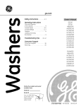
1
User- and installation manual
Lucius 140 T, Lucius 140 R
Lucius 140 CR 1/3, Lucius 140 CR 2/3
WARNING - THE COMBUSTION CHAMBER OF THIS
STOVE SHOULD ONLY BE OPENED AND SERVICED BY A
REGISTERED GAS INSTALLER
(i.e. GAS SAFE REGISTERED ENGINEER[GB])
These instructions should be left with the customer
for future reference
This Manual Covers the following appliances:
Lucius 140 T, Lucius 140 R, Lucius 140 CR 1/3, Lucius 140 CR 2/3
Contents
GENERAL INFORMATION............................................................................................................3
Important Safety Notice..................................................................................................................3
General Fitting Information....................................................................................................4
USER INFORMATION...................................................................................................................5
Remote Control Electronic Ignition System RCE GV60................................................................5
INSTALLER INFORMATION.......................................................................................................10
Ventilation............................................................................................................................10
General Balanced Flue Notes / Appliance Fireplace installation.........................................10
Terminal Locations Wall Mounting.......................................................................................12
Terminal Locations Roof Termination...................................................................................13
Concentric Flue Parts Identification.....................................................................................14
Flue restrictor.......................................................................................................................21
Wall Terminal Terminations..................................................................................................22
Vertical Roof Terminations...................................................................................................23
Installing Remote Control Electronic Ignition System GV60........................................................26
Arranging The Ceramic Fire-bed..................................................................................................27
Log Arrangements...............................................................................................................27
Gravel Arrangements...................................................................................................................30
COMMISSIONING THE APPLIANCE..........................................................................................30
Installing the fire ..IMPORTANT INSTALLATION TIPS............................................................31
Servicing Instructions...................................................................................................................34
Troubleshooting............................................................................................................................35
TECHNICAL INFORMATION.......................................................................................................37
Dimensions...................................................................................................................................37
Technical Details..........................................................................................................................41
Warranty.......................................................................................................................................44
2
GENERAL INFORMATION
Important Safety Notice
ing regulations. It is therefore recommend that
a registered gas installer be employed for this
task. The engineer will provide you with information about the safety limits of the installation and
should fix a notice plate in a place where it can
be readily seen.
This appliance has a ceramic Fire-bed arrangement; this contains Refractory Ceramic Fibres,
which are man-made vitreous silicate fibres. Excessive exposure to these materials can cause
irritation to eyes, skin and respiratory organs.
Hence we recommend that when handling these
materials the release of dust should be kept to
a minimum. During installation and servicing we
recommend that a HEPA filtered vacuum be used
to remove any dust and soot in and around the
fire. If any of the ceramic fire-bed components
need to be replaced we recommend that the removed parts be sealed in a heavy-duty polythene
bag, and be labelled as RCF waste. RCF is not
“Hazardous waste” and can be disposed of at a
licensed tipping site for the disposal of industrial
waste.
This appliance is designed as an efficient heating
device and consequently all body parts become
very hot in use. Except for the control knob and
control access door, which are designed to stay
cool, all other parts are working surfaces and
should not be touched.
The glass and frame on this appliance acts as
a fireguard conforming to BS: 1945 – 1971 and
satisfies the Heating Appliance (Fireguards)
regulations 1991. No part of the window or frame
should be permanently removed. It does not give
protection for young children aged or infirm,
extra guarding(conforming to BS8423: 2002)
should be considered so the special hazards that
exist in nurseries and other places where there
are young children, aged or infirm persons are
minimized.
The appliance incorporates a permanent pilot.
This is located on the front of the burner, and
must not be adjusted by the installer. This system
must not be put out of operation, and if any parts
require changing, only original manufacturer parts
shall be used.
Bearing in mind that the heat given off by this
appliance may affect articles placed close to it,
curtains should not be placed within 30cm.
This appliance is designed to be used either Natural or LPG gas however, each individual appliance
is only capable of running off the type of gas
specified at the time of purchase. It is important
to note that once a type of gas has been specified the stove cannot run off any other type. The
type of gas that your stove is capable of burning
is stated on the data information panel.
The appliance is not designed as a dryer. It is not
therefore recommended that the appliance be
used in such a manner. Do not place any articles
within 30cm of this appliance as this may result
in damage to the articles.
This appliance has been designed, tested and
approved to meet standards in place for product use, performance and safety. Installation of
your appliance must comply with current build-
The installation must be carried out in accordance
with the following regulations:
The Building Regulations issued by the Depart
3
GENERAL INFORMATION
General Fitting Information
ment of the Environment, the Building Standards
(Scotland) (Consolidation) Regulations issued by
the Scottish Development Department.
Inlet pipe connection
8mm compression
Chimney requirements Balanced Flue
Flue monitor
Permanent Pilot
BS 5440 part 1, BS 5871 part 2 and BS 6891.
User control: Variable rotary control inc. integrated
Piezo ignition, Permanent pilot facility, Flame failure device and Oxygen Depletion Cut-out.
In the Republic of Ireland the installation must
also conform to the relevant standards, particularly in regard to flue sizing and ventilation. Refer
to documents IS813, ICP3, IS327 and any other
rules in force.
Before installation of these appliances, the area
into which the fire is to be fitted must be cleared
of all debris (including dust), in particular combustible material.
This appliance must be installed in accordance
with the rules in force and used only in a sufficiently ventilated space, and is intended for use
on a gas installation with a governed meter.
The appliance must sit on a hearth (or base surface) sufficient to support the weight of the fire.
The firebox must then also be secured. Adjustable brackets are supplied on the firebox for this
purpose.
Before installation, ensure that the local distribution conditions (identification of the type of gas
and pressure) and the adjustment of the appliance
are compatible. The technical specification of this
appliance is given on the rear page of this manual.
Prevention of rust: Always switch the Fire completely off after use. This saves gas and prevents
corroding of your fire.
Do not use the appliance if the glass front door
or panel has been broken, removed or is open.
Note:
Since the appliance is a source of heat, circulation
of air occurs. Therefore it is of importance that you
do not use the appliance shortly after a renovation
of the home. Because of the natural circulation
of air, moist and volatile components from paint,
building materials, carpet etc. will
be attracted. These components can settle themselves down onto cold surfaces in the form of soot.
4
Remote control electronic ignition
system RCE GV60
- temperature display in degrees Celsius or
Fahrenheit;
- time;
thermostat function;
The appliance
supplied with
a remotesyscontrol. - -temperature
display in degrees Celsius or
Remote
control is
electronic
ignition
- temperature
in degrees
Celsius or
- timer for display
thermostat
function.
Remote
control
ignition
Ignition,
controllingelectronic
the flame height
and switchFahrenheit;
tem
RCE GV60
Fahrenheit;
system
GV60 by the remote control that
ing offRCE
are performed
- time;
- time;
the function;
communication code
operates a
the
control control.
hatch. For
- Setting
thermostat
The appliance
is receiver
supplied in
with
a remote
- thermostat
function;
the application
The some
appliance
is supplied
with
a remote
appliances,
control
hatch
isswitchsupplied.
- Prior
timerto
forputting
thermostat
function. into operation, a
Ignition,
controlling
the no
flame
height
andcontrol.
- timer
for thermostatcode
function.
communication
must be set between the
Ignition,
controlling
theby
flame
height
and
switchIn are
that
case, the
receiver
is placed
under
ing
off
performed
the remote
control
that the
USER INFORMATION
USER INFORMATION
remote control
and the receiver.
The code is choing off
are
performed
by control
the remote
control
that are Setting
appliance.
Theinreceiver
andhatch.
remote
the communication
code
operates
a receiver
the
Forcontrol
some
Setting
communication
codeavailable
sen the
randomly
from
the 65000
codes.a
operates
a no
receiver
thereceiver
control
hatch.
battery
powered.
The
requires
4
Prior
to putting
the application
into operation,
appliances,
controlin
hatch
is supplied.
In For
that
Prior
toaputting
application
into
operation,
a the
As
result, the chance
that other
remote
controls
some
appliances,
control
hatch
supplied.
penlite
(AA type)
batteries,
the
control
communication
code must
be set
between
case,
the
receiver
isno
placed
under
theisremote
appliance.
communication
be set
between
the
near you
arecode
using
the receiver.
same
code
and
affect
the
In that
case,and
the
receiver
is placed
underpowthe the
requires
3 xremote
AAA
penlites
.At battery
normal
use,
remote
control
andmust
the
The
code
is choThe
receiver
control
are
remote
control of
and
the appliance
receiver.
codesmall.
iscodes.
cho- As
operation
your
is
very
appliance.
The
receiver
and
control
areyear.
batteries
will
have
an
average
of one
sen
randomly
from
the
65000The
available
ered.
The receiver
requires
4 remotelife
senarandomly
from
the 65000
available
codes.
battery
powered.
receiver
4control
You(AA
cantype)
also The
use
an
optional
adapter.
Ask your
result, the
chance
that other
remote
controls
penlite
batteries,
therequires
remote
As anear
result,
chance
other remote
controls
Follow
the
procedure
penlite
(AA
batteries,
the
remote
control
installer
for
information.
Innormal
that case
you
youthe
are
using that
the described
same
codebelow:
and
affect the
requires
3 xtype)
AAA
penlites .At
use,
the will
you are
using
the
same
code
and
affect
the
Hold
down
the
reset
button
on the
receiver,
requires
3
xhave
AAA
penlites
.Atnear
normal
use,
the near
needwill
a 230
V connection
your
appliance.
operation
of your
appliance
is very
small.
batteries
an
average
life of
one
year.
of your
is very small.
until you
hearappliance
two consecutive
sound signals
batteries
will use
havean
anoptional
averageadapter.
life of one
You
can also
Askyear.
your operation
(see fig.
After the
second,below:
longer signal,
You canfor
also
use an optional
your
Follow
the2).
procedure
described
installer
information.
In that adapter.
case youAsk
will need
procedure
described
below:
let the
godown
of
thethe
reset
button.
for information.
In that
case you will Follow
Hold
reset
button
on the receiver,
ainstaller
230 V connection
near your
appliance.
down
the
reset
on thesound
receiver,
Press
button
need a 230 V connection near your appliance. Hold
until
you
hear
two button
consecutive
signals
until
youfig.
hear
consecutive
sound
signals
(see
2).two
After
the second,
longer
signal, let
(see
fig.
2).
After
second,
longer
on
control
within
20signal,
seconds,
go
ofthe
theremote
resetthe
button.
let Press
go
of the
until
youreset
hearbutton.
a sound signal: this is the
button
Press
button
confirmation
of a correct communication.
!Caution
When
installing
a new
remote conon
the remote
control
within
20 seconds,
until
on you
the
remote
control
within
20
trolhear
or receiver,
you
must
set
a seconds,
newconfirmacommua sound
signal:
this
is
the
until
you
a sound
signal: this is the
nication
code.
tion
of ahear
correct
communication.
confirmation
of a correct
communication.
!Caution When
installing
a new remote control
!Caution
When you
installing
a new
remote
conor receiver,
must set
a new
communicatroltion
or receiver,
The appliance’s standard functions such as ignicode. you must set a new communication code.
tion, controlling the flame height, standby (pilot
1
1
burner) position and switching off ,are performed
in the MAN position.
the display
of as
theigniremote
The appliance’s
standardIn
functions
such
The you
appliance’s
standard
functions
such as (pilot
ignican seethe
theflame
letters
MAN. standby
tion,
controlling
height,
tion,In
controlling
the remote
flame
height,
standby
addition,
the
control
canperformed
also(pilot
be used
burner)
position and
switching
off ,are
position
and switching
off ,are
performed
set
aposition.
number
of the
additional
functions:
inburner)
thetoMAN
In
display
of the
remote
in the
MAN
In the
display of the remote
you
can
seeposition.
the letters
MAN.
can see
theremote
letterscontrol
MAN. can also be used
Inyou
addition,
the
addition,
the remote
controlfunctions:
can also be used
toInset
a number
of additional
to set a number of additional functions:
2
2
5
5
5
USER
USERINFORMATION
INFORMATION
USER INFORMATION
I gI gn ni ti et e t ht hee aappppl li iaannccee aass ffoollll oo w
MAN MAN
position
position
w ss ::
eet b
uet t oanp p
AA
nn ctethe
h ea g
a sf o clcontrol
o
By
briefly
pressing
the SET
button,
you will
MAN
position
g nSi tSet
th
l io
aon
sgas
loonwt sr o: l tto
By
briefly
pressing
the SET
button,
you go
will Igo
button
controlled
automatically).
through
the
following
functions:
By briefly
pressing
the
SETfunctions:
button, you will go SetON
button
A Bon
gas control
to
through
the following
ON(button
(button
Bisisthe
controlled
automatically).
is is
located
in
thethe
control
hatch
or
MAN
→ the→
TEMPTEMP
→functions:
TEMP
→ (P*)TIMER
→ ON The
through
following
(button
Bcontrol
is controlled
automatically).
MAN
→ TEMP
→ (P*)TIMER
Thegas
gascontrol
located
in
control
hatch
placed
under
the appliance.
MAN →
→ MAN TEMP → TEMP → (P*)TIMER The isgas
isunder
located
the control hatch
or
iscontrol
placed
theinappliance.
✹
where,
depending
on theon
timer
setting:
→ MAN
or is placed under the appliance.
where,
depending
the timer
setting:
(P*)
is(P*)
displayed
ason
P1the
, P1
where,
depending
timer
is displayed
as ,P1
, setting:
, P1, P2 , P2 ,
,
P2
.
(P*) isP2
displayed
, P2
,
. as P1 , , P1
P2
.
You can
go back
to the
position
by by
Youalso
can also
go back
to MAN
the MAN
position
pressing
the button
(large
flame)flame)
or
You can
also
go
back
to the MAN
position
by or Simultaneously
pressing
the
button
(large
Simultaneouslypress
pressthe
thebuttons
buttons
and
on
remote
control.
(small
flame).
pressing
theflame).
button
(large flame) or Simultaneously
press
buttons
(small
and
onthe
thethe
remote
control.
✹
✹
(small flame).
and
on the remote control.
Let
!Caution
- When -pressing
the buttonsthe
(withbuttons
the
!Caution
When pressing
Letgo
goofofthe
thebuttons
buttons when
when aa short
short sound
sound
signal
indicates
that
the
ignition
process
exception
of
the
SET
button),
the
transmission
!Caution
When
pressing
buttons
Let go
of the
buttonsthat
when
a short process
sound has
(with -the
exception
of thethe
SET
button), the
signal
indicates
the ignition
has
started.
symbol
) willsymbol
appear
indicate
that signal
(with transmission
the( exception
of
the SET
the
indicates
that the ignition process has
( to button),
) will appear
to been
been
started.
InIn
succession:
transmission
takingtransmission
place
the
remote
transmission
symbol
( between
) will is
appear
toplace
been
started.
indicateis that
taking
succession:
- the
continuous
signals
will will
indicate
that the
control
and
thetransmission
receiver;
indicate
that
is taking
place
In succession:
between
the
remote control
and the
receiver;
- the
continuous
signals
indicate
thatignithe
tion
process
is
active;
-between
The- receiver
acknowledges
the
transmission
the
remoteacknowledges
control and the
- the ignition
continuous
signals
will indicate that the
The
receiver
thereceiver;
transmission
process
is active;
- a- a
short
sound
signal
willwill
indicate
thatthat
thethe
ignition
with
sound
signal;
- Theareceiver
acknowledges
process
is active;
with
a sound
signal; the transmission ignition
short
sound
signal
indicate
igniprocess
has
finished;
-with
Thea- appliance
will
automatically
enter
the
sound
signal; will automatically enter the
- a short
signal
indicate that the igniThe
appliance
tionsound
process
has will
finished;
the
will
standby
position,
if there
no transmission
for tion -process
- Thestandby
appliance
will
automatically
the
has finished;
position,
ifisthere
is noenter
transmission
- theappliance
appliance
willautomatically
automaticallyswitch
switch through
through
to
the
highest
position
of
the
main
burner,
6
hours.
standby
position,
will automatically
throughwhich
for 6
hours. if there is no transmission - the appliance
to the highest
position of theswitch
main burner,
which
will
start
few
seconds.
for 6 hours.
to the
highest
ofa a
the
main
burner, which
will
starttoposition
toburn
burninin
few
seconds.
Set the
remote
controlcontrol
to the MAN
position.
will start to burn in a few seconds.
Set
the remote
to the
MAN position.
Caution
- If- the
pilot
burner
is not
after
Set the remote control to the MAN position.
Caution
If the
pilot
burner
isburning
not burning
3 after
ignition
attempts,
you must
close
the gas
Ignition
Caution
- If
the
pilotattempts,
burner
isyou
notmust
burning
Ignition
3 ignition
close
the
and
the
installer;
Caution
- During
the ignition
are not you
Ignition
aftertap
3
ignition
attempts,
must close the
Caution
- During
theprocess,
ignitionyou
process,
gas
tapcall
and
call
theyou
installer;
When
allowed
operate
control
buttonprocess,
Bcontrol button
Caution
During
theto
ignition
you gas
andigniting
call
thethe
installer;
areto-not
allowed
operate
B -tap
- When
igniting
thepilot
pilotburner,
burner,you
youwill
will hear
hear
sound
signals.
After
thethe
lastyou
short
sound
sigon
gas
control
manually
arethe
not
allowed
operate
control button B - When
igniting
the pilot
burner,
will
hear
on
the
gas to
control
manually
sound
signals.
After
last
short
sound
nal,
the main
burner
should
be largely
-on
Always
wait
5wait
minutes
afterafter
the pilot
burner
the
gas
control
sound
signals.
last should
short
sound
- Always
5manually
minutes
the pilot
burner
signal,
the After
main the
burner
be ignited
largely
within
10
seconds.
If be
thislargely
isIfnot
has
gone
out,5before
you
re-ignite
- Always
minutes
after
there-ignite
pilot burner signal,
theabout
main
burner
should
haswait
gone
out, before
you
ignited
within
about
10 seconds.
thisthe
is
case,
you
must
close
the
gas
tap
and
warn
the
appliance;
has gone
out, before you re-ignite
ignited
about
seconds.
If this
is and
the appliance;
notwithin
the case,
you10
must
close the
gas tap
installer;
the appliance;
not your
the
case,
youinstaller;
must close the gas tap and
warn
your
- If-your
the
appliance
ignites
withwith
a pop
sound,
you
warn
installer;
If the
appliance
ignites
a pop
sound,
must
close
theignites
gas
and
- If the
appliance
with
a pop
you
must close
thetap
gas
tap
and sound,
your
installer.
youcontact
must
close
the
gas tap and
contact
your
installer.
3
B
3
A
A
contact your installer.
!Tip
!TipAAlittle
littlemotor
motorwill
willstart
start to
to run
run when
when the
the
burner
operates,
will
be
able
to hear
!Tipmain
Amain
little
motor
will
startyou
toyou
run will
when
burner
operates,
bethe
able
to
it.
main hear
burner
it. operates, you will be able to
B
6
hear
6 6 it.
USER INFORMATION
Flame height / standby
The flame height can be adjusted continuously by
using the buttons
and
Time
The display can indicate time.
After placing the battery or simultaneously press(large flame) and
ing
By continuing to lower the flame height, the appliance can be set to the standby position; this
means that only the pilot burner will still be burning.
Press button
(small flame) to lower the
flame height and/or to set the appliance in the
standby position.
Press the button
(large flame) to raise the
flame height and/or to switch on the main burner
from the standby (pilot burner) position.
(small flame), the time indication will flash on
the display and you will be able
to adjust the time.
Simultaneously press and until the time indication flashes on the display.
Press the button
(large flame)
to set the hours.
Press the button
minutes.
(small flame) to set the
Caution - If you continue to press down button
Press OFF
to return to the MAN position, or wait for the system to automatically return
to the MAN position.
(large flame) on the remote control,
the main burner should be largely ignited
within about 10 seconds. If this is not the
case, you must close the gas tap and warn
your installer;
- If the appliance ignites with a pop sound,
you must close the gas tap and contact your
installer.
Thermostat function
Using the thermostat function you can set
two temperatures, which can be controlled
thermostatically. These temperatures are
referred to as day temperature and night
temperature.
The
TEMP and
TEMP symbols on the
display refer to day and night temperature
respectively.
The room temperature is compared to the set
day/night temperature and then the flame height
is automatically controlled in order to reach the
set temperature.To be able to use the day/night
temperature function, the appliance must be
in the standby position.
✹
Switching off
Switch the appliance off by pressing the OFF
The pilot burner will also go out.
button.
Temperature display
The room temperature can be indicated on the
display in degrees Celsius (°C) using a 24 hour
clock or degrees Fahrenheit (°F) using a 12 hour
clock.
Simultaneously press OFF
(small flame)
appears.
and
, until the correct display
7
!Caution - Always leave the remote control
at the same place, so that the thermostat is
able to ‘feel’ the room temperature;
- Make sure this place is free from influences
such as draught, heat from radiators
and direct sunlight.
USER INFORMATION
Timer for thermostat function
Using the timer enables you to set two times per
24 hours for switching on the day temperature
and two times per 24 hours for switching on the
night temperature.
In order to control the night temperature, it should
be set to at least 5 °C / 40 °F.
If the night temperature is set to the “-- ” position,
the appliance will remain in the standby position.
The appliance will only switch on at the next
switch-on time of the day temperature.
The appliance must be in standby position in order
to be controlled by the timer.
Example
By using the Y TEMP function you can keep the
day temperature at 20 °C; while
you use the 4 TEMP function at night to maintain
a temperature of 15 °C.
Setting day/night temperature
By using the SET button, you will go through the
following functions:
MAN →
TEMP →
TEMP → (P*)TIMER
→ MAN
✹
Briefly press the SET button to enter
the
TEMP or the
TEMP position.
Press the SET button until the temperature on the
display flashes.
Set the required temperature by using the buttons
and
✹
Example of switch times
You have set a day temperature and night
temperature of, for example, 20 °C and 15 °C.
P1
TIMER = 7 hours; the temperature will
go to 20 °C at 7 am.
P1
TIMER = 9 hours; the temperature will go
to 15 °C at 9 am.
P2
TIMER = 17 hours; the temperature will
go to 20 °C at 5 pm.
P2 TIMER = 22 hours; the temperature returns
to 15 °C at 10 pm.
✹
!Caution - The minimum temperature you can set
is 5 °C / 40 °F;
- Control of the night temperature is switched off
by lowering the temperature
until two stripes (“--”) appear on the display.
Press the OFF button or wait until position
TEMP or
TEMP appears on the
display.
✹
✹
Activating the thermostat function
For activating the thermostat function, you must
proceed with the following
steps:
Place the appliance in the standby (pilot burner)
position using button
(small flame).
Set the day/night temperature.
✹
Choose the
TEMP or
the SET button.
TEMP function using
8
USER INFORMATION
Replacing the battery
If the battery is almost empty, the display will
show “BATT”.
Setting times for the timer
To set the timer, proceed as follows:
Set the day and night temperature as described
above
Briefly press the SET button to enter the (P*)
TIMER position.
Press the SET button until P1
TIMER is
displayed and the time flashes.
Set the first switch on time of the day temperature
To replace the battery, proceed as follows:
Remove the cover at the back side of the
remote control.
Disconnect the 9V block battery from / connect
the 9V block battery to the connector.
✹
large flame) and
using the buttons
(small flame)
.
Briefly press the SET button to set the next time
of the cycle, P1
TIMER.
Successively set the times P2
TIMER and
P2
TIMER.
Press the OFF button or wait until position (P*)
TIMER appears on the display.
!Caution - Observe the “+” and “-” poles of the
batteries and the connector;
- Use alkaline batteries;
- Batteries are regarded as “small chemical
waste” and may therefore not be disposed
with the household rubbish.
✹
Place the battery in the holder.
Replace the cover.
Activating the timer function
Follow the steps below for activating the timer
control:
Place the appliance in the standby (pilot burner)
(small flame).
position using button
Set the day/night temperature if you have not yet
done so;
Set the timer times P1
TIMER, P1
TIMER,
P2
TIMER and P2
TIMER.
✹
✹
Choose the (P*) TIMER function using the SET
button.
9
INSTALLER INFORMATION
InstallatIon
restricted to the Flue systems as specified by
the supplier, thus the appliance must only be
installed with the original flue system, no others
may be used
Before beginning the installation, check that the
details on the rating plate correspond to the gas
type and pressure to which the appliance will be
connected.
This appliance can be installed in a completely
sealed or mechanically ventilated house without
extra ventilation and/or fume extraction.
The gas fire, in combination with the concentric
flue system , has been approved in accordance
with the European CE-norm for gas appliances
and may therefore be used only with this system.
The guarantee is invalidated if the appliance is
(completely or partially) installed using a different system.
General Balanced Flue Notes
The concentric flue systems can be used with
either a newly-built or existing chimney.
Ventilation
These appliances are designed with the “Firebox” raised up off the ground level by the built in
“Base unit”.
There are many possibilities for installing this
Concentric Balanced Flue system into a building,
both Roof and Wall terminations are possible,
and the flue can either be built into an existing
chimney or a completely new flue system may
be constructed.
Thus these appliances require no special Hearth
arrangements, as the floor will not get hot and is
protected by the steel construction of the “Base
unit”.
The system is based upon a Concentric Flue
system which utilises an inner flue of 100 or 130
mm diameter which passes through an outer flue
of 150 or 200 mm diameter. The flue gasses that
are the products of combustion of the fire, pass
through the inner flue and are safely vented to
the outside environment. The gap between the
inner and outer flues is the channel by which the
stove is supplied with air for combustion.
The appliance must not be fitted against a rear
wall constructed from a combustible material; a
gap of 300mm should be given all round the stove
before combustible materials may be used in the
wall construction.
If the appliance has to be located in an opening,
a minimum clearance of 50mm should be allowed
to non-combustible materials.
These concentric flues terminate outside of the
property in a terminal, this terminal will keep the
expelled gasses and the fresh air for combustion
separate. It is important that the terminal is not
blocked, a suitable guard maybe required if the
terminal is located at a “Low” level (usually when
the terminal is within 2m of floor level).
If the appliance is located in a recess, then the
recess must have adequate ventilation, we recommend a minimum total vent area of 400 cm².
The stove must be located at least 300 mm from
any combustible materials outside the chimney
breast.
The Balanced Flue gas appliance can be installed
as an insertion into an existing or new fireplace.
If an existing Flue or Chimney is to be utilised,
then the installation engineer must be consulted.
If the chimney has been previously used it must
be professionally cleaned and certified as being
sound and fit for use.
Appliance Fireplace Installation
After selecting the appliance location, install a gas
connection for the appliance in approximately the
desired location of the gas controls.
The European CE approval on this appliance is
The gas controls are already connected to the
10
INSTALLER INFORMATION
appliance. The controls need to be located in the
control access box, so an appropriate position for
the access box need to be determined.
This appliance has adjustable legs, these must
me set to stabalise the fire before flue position is
finalised.
completely open and unobstructed sides. The
distance between the lowest part of the roof and
the top of the terminal should be at least 600mm.
Note: A covered passageway should not be
treated as a carport. Flues should not be sited in
a covered passageway between properties.
Do not make any adjustments to the appliance,
except the leg length.
Basements,Lightwells and Retaining
walls
The appliance and Flue system should be fitted
with a minimum clearance of 500mm from any
combustible objects or materials, this includes
any combustible materials used for the fireplace
construction.
Flue terminals should not be sited within the confines of a basement area, light well or external
space formed by a retaining wall, unless steps
are taken to ensure the products of combustion
can disperse safely at all times. It may be possible to install this Balanced Flue system in such a
location provided that it is not sited lower than 1m
from the top level of that area to allow combustion
products to disperse safely.
As this is a room sealed appliance and the appliance stands on appropriate legs, a hearth is not
required for this appliance.
The Fireplace should be ventilated with openings
giving a total free vent area of 400 cm².
Flue terminals should be sited to ensure total
clearance of the combustion products in accordance with the inclosed information.
A gap of 50mm should be left all round the appliance.
When the products of combustion are discharged,
they should not cause a nuisance to adjoining or
adjacent properties and they should be positioned
so that damage cannot occur to other parts of the
building. If the outer wall surface is constructed
of combustible material, a non-combustible plate
should be fitted behind the terminal projecting
25mm beyond the external edges of the terminal.
If a shelf is to be fitted above the fireplace opening,
a gap of 150mm minimum should be left between
the opening and the shelf.
The brackets supplied may be used fore securing
the appliance to a rear wall.
Timber Frame Construction
Whilst it is possible to install room-sealed appliances in timber frame properties, great care needs
to be taken to ensure that the flue assembly does
not interfere with the weather proofing qualities
of any outer wall which it may penetrate. Before
attempting this work, further details need to be
referenced, (e.g. “Gas Installations in Timber
Frame Buildings” from the CORGI installer series
in the UK).
Carport or Building Extension
Where a flue terminal is sited within a carport or
building extension, it should have at least two
11
INSTALLER INFORMATION
INSTALLER INFORMATION
Terminal Locations Wall Mounting
Dimension
TerminalTerminal
PositionPosition
Dimension
A*
below anbelow
opening,air
brick, opening
window window
etc.
A*Directly Directly
an opening,air
brick, opening
etc.
B
DistanceDistance
(mm) (mm)
600
600
opening,air
brick, opening
window window
etc.
BAbove an
Above
an opening,air
brick, opening
etc.
Adjacent
to
an
opening,air
brick,
opening
window
etc.
C
Adjacent to an opening,air brick, opening window etc.
300
300
400
400
soil pipes
orpipes
drain or
pipes
DBelow gutters,
Below gutters,
soil
drain pipes
EBelow eaves
Below eaves
300
300
300
300
of car port
roofport roof
FBelow balconies
Below balconies
of car
pipe
or soil
GFrom a vertical
From a drain
vertical
drain
pipepipe
or soil pipe
600
600
300
300
600
600
I
internal
external
corner corner
HFrom anFrom
an or
internal
or external
or balcony
level
I Above ground
Above roof
ground
roof or balcony
level
300
300
J
terminal
JFrom a surface
From a facing
surfacethe
facing
the terminal
600
600
K
facing the
terminal
600
KFrom a terminal
From a terminal
facing
the terminal
opening
in the car
(e.g.port
door
, window
into the dwelling)
LFrom anFrom
an opening
in port
the car
(e.g.
door , window
into the dwelling) 1200
600
C
D
E
F
G
H
L
M
N
P
Q
1200
from a terminal
on the same
wall
MVerticallyVertically
from a terminal
on the
same wall
Horizontally
from
a
terminal
on
the
same
wall
N
Horizontally from a terminal on the
same wall
1500
1500
300
300
on the roof
PFrom a vertical
From a structure
vertical structure
on the roof
with roofwith roof
QAbove intersection
Above intersection
600
600
150
150
* I addition, the terminal should not be nearer than 300mm to an opening in the building fabric
* I addition, the terminal should not be nearer than 300mm to an opening in the building fabric
formed for the purpose of accomodating a built in element such as a window frame.
formed for the purpose of accomodating a built in element such as a window frame.
12
12
INSTALLER INFORMATION
Terminal Locations Roof Termination
“Distance” = minimum distance required for positioning of the outlet to avoid adverse effects with
respect to:
A.
A ventilation opening serving an occupied room, a toilet or a bathroom
B.
A heating air supply, when the supply flows through an occupied room.
C.
A window that can be opened and that is near an occupied room, a toilet or a bathroom.
To avoid adverse effects
(*)
Distance: outlet A,B or C
At the same roof level
>6 m (*)
At a different roof level
>3 m (*) (**)
At a lower positioned wall
>2 m (**)
At a higher sloping surface
>6 m (***)
If the required distance cannot be achieved, the outlet position rules take precedence.
(**)
If the outlet is positioned at least 1 m higher than the intake supply opening, or a window that
can be opened.
(***) If the required distance cannot be achieved, the position of the outlet must be at least 1 m above
the highest facade/roof.
Important note for Roof Terminations (C31).
When installing the appliance with a roof termination (classification C31), it is important to fit a flue
restriction strip across the flue outlet inside the stove, see notes page 21.
Minimum Vertical Length notes.
Roof terminations may be installed from a minimum height 1.0 m this is shown on the pages that follow.
13
INSTALLER INFORMATION
Concentric Flue Parts Identification
The following pages identify the parts that may be used in the Balanced Flue installation of this
appliance.
The Item number in the table refers to the item number of the part in the Identification pages, this
Item number is also the number that will be used to identify parts in the Installation suggestion
diagrams.
Item
Description
A
B
C
D
E
F
G
1
2
3
4
5
6
7
8
9
10
11
12
13
14
15
16
Appliance
Appliance Connector
Flue Adaptor
Chimney or Flue, Fully Gas Tight Ø150 minimum
Chimney or Flue, Fully Gas Tight Ø160 minimum
Stainless Steel Flexible Chimney Liner Ø100, AISI 316Ti
Stainless Steel Flexible Chimney Liner Ø150, AISI 316Ti
Concentric Flue Pipe 250mm Length
Concentric Flue Pipe 500mm Length
Concentric Flue Pipe 1m Length
Locking Band
Protection Band
Concentric Flue Pipe Adjustable Length 50 - 300mm
Vertical Terminal
Horizontal Terminal (Excentric Exit) Ø100
Mounting Band
Wall Band Adjustable
Concentric Flue 90°
Concentric Flue 45°
Concentric Flue 15°
Storm Collar
Flat Roof Flashing (Aluminium)
Flat Roof Flashing
18
19
20
21
22
23
24
25
Slope Roof Flashing 5° - 30°
Slope Roof Flashing 20° - 45°
Adjustable Roof Plate (Supplied as pair)
Wall Cover
Flue reducer Ø130 - Ø100
Horizontal Terminal (Excentric Exit) Ø130
Concentric Flue 90° with Inspection Cover
Inspection Element
14
Ø100
Part No.
US 25 100
US 50 100
US 100 100
USKB 100
USAB 100
USPP 100
USDVC2 100
USDHCE 100
USEB 100
USMB 100
USB 90 100
USB 45 100
USB 15 100
USSR 100
USDPAL 100
USDP 100
USDH 100
USLS 100
USCP 100
USMPG 100
USBI 100
USI 100
Ø130
US 25 130
US 50 130
US 100 130
USKB 130
USAB 130
USPP 130
USEB 130
USMB 130
USB 90 130
USB 45 130
USB 15 130
USSR 130
USDPAL 130
USDP 130
USDH 130
USLS 130
USCP 130
USMPG 130
USVK 10 130
USDHC 130
USBI 130
USI 130
INSTALLER
INSTALLERINFORMATION
INFORMATION
15
15
INSTALLER
INSTALLERINFORMATION
INFORMATION
16
16
INSTALLERINFORMATION
INFORMATION
INSTALLER
17
17
INSTALLER
INSTALLER INFORMATION
INFORMATION
18
18
INSTALLER INFORMATION
INSTALLER INFORMATION
22
USVK 100 130
REDUCER Ø130 - Ø100
23
USDHC 130
HORIZONTAL TERMINALØ130
19
INSTALLER INFORMATION
INSTALLER INFORMATION
24
USBI 100 130
Elbow 90° with inspection cover
25
USI 100 130
Inspection Element
20
20
INSTALLER INFORMATION
FLUE RESTRICTOR
- When using Flue system (200/130) with a wall terminal DON’T use any restrictor
- When using Flue system (200/130) and vertical is > 1.25 m and then direct through the wall
(and no more horizontal) use flue restrictor 35 mm.
- When using a roof terminal Flue system (150/100) and vertical is between1.25 m and 2.0 m
use restrictor 35 mm.
- When using a roof terminal Flue system (150/100) and vertical is > 2.0 m use restrictor 60 mm.
The 60 mm Flue restrictor is located on the inside of the Fire near the Flue outlet. Undo 1 of the
bolds and turn the restrictor over the flue outlet.
The 35 mm flue restrictor is packed seperately with the Fire.
21
INSTALLER INFORMATION
Rigid
RigidBalanced
BalancedFlue
FlueConnection
ConnectionPossibilities
Possibilities
Horizontal
HorizontalWall
WallTermination
Termination
Lucius
Lucius140
140T,T,Lucius
Lucius140
140R,R,Lucius
Lucius140
140CR
CR1/3,
1/3,Lucius
Lucius140
140CR
CR2/3
2/3
Diameter
DiameterConcentric
ConcentricFlue:
Flue:200/130
200/130
Lucius
LuciusFires:
Fires:
Minimal
vertical
Minimal verticalheight
height“V”
“V”isis5050cm
cmplus
plusbent.
bent.
Maximum
Maximumheight
height“V”
“V”whilst
whilstusing
usinga awall
wallterminal:
terminal:3 3meter
meter
Horizontal
Horizontalpossibilities:
possibilities:
0,5
meter
0,5meter
metervertical
verticalgives
givesmaximum
maximumhorizontal
horizontal0,5
1 meter
1.0
meter
vertical
gives
maximum
horizontal
1,0
meter
1.0 meter vertical gives maximum horizontal 2 meter
1,5
meter
vertical
gives
maximum
horizontal
1,5 meter
1,5
meter
vertical
gives
maximum
horizontal
3 meter
2,0 meter vertical gives maximum horizontal 2,0 meter
2,5 meter vertical gives maximum horizontal 2,5 meter
3,0 meter vertical gives maximum horizontal 3,0 meter
22
22
INSTALLER INFORMATION
Vertical Roof Terminations
When installing the appliance with a roof termination (classification 31) it is important to fit a flue
restrictor across the flue outlet inside the fire.
Roof terminations will need the 60 mm flue restrictors fitting. This is delivered with the fire.
Distance “V” = 1m– 11m (min – max)
We recommend using flue reducer
USVK to flue dimension 150/100.
23
INSTALLER INFORMATION
Vertical
Roof
Mounted
Termination
with
Elbow
Rigid
Concentric
Flue
Vertical
Roof
Mounted
Termination
with
Elbow
forfor
Rigid
Concentric
Flue
We recommend using flue reducer
USVK to flue dimension 150/100.
24
24
INSTALLERINFORMATION
INFORMATION
INSTALLER
Vertical
VerticalRoof
RoofMounted
MountedTermination
Terminationwith
withAngled
AngledElbow
Elbowfor
forRigid
RigidConcentric
ConcentricFlue
Flue
We recommend using flue reducer
USVK to flue dimension 150/100.
2525
INSTALLER
INSTALLERINFORMATION
INFORMATION
Installing
the controls
Installing
the controls
Electronic
Ignition
System
RCERCE
GV60)
Electronic
Ignition
System
GV60)
This requires
no external
electrical
powerpower
to
This requires
no external
electrical
to
operate.
The receiver
unit hasunit
onlyhas
oneonly
lead.one
Thislead.
operate.
The receiver
lead has
plug.
Thisplug.
plugThis
fits into
Thisone
leadsingle
has one
single
plug the
fits into
connector
block on block
the front
of the
Control
the connector
on the
frontGas
of the
Gas Conunit, the
of this plug
is important.
trolorientation
unit, the orientation
of this
plug is important.
InstallInstall
the batteries
into the
and and
the the
the batteries
intoreceiver
the receiver
handset;
these these
will bewill
4 x 1,5V
alkaline
handset;
be 4AA
x 1,5V
AA and
alkaline
3 x AAA
andalkaline
3 x AAArespectively.
alkaline respectively.
Setting
the electronics
code:code:
Setting
the electronics
The receiver
has to has
select
code
the handset,
The receiver
to the
select
theofcode
of the handpleaseset,
follow
the follow
procedure:
please
the procedure:
1) Power
up handset
1) Power
up handset
2) Power
up receiver
(LED (LED
flashes)
2) Power
up receiver
flashes)
3) Push
“reset”“reset”
buttonbutton
on receiver
till long
3) Push
on receiver
tillbeep
long beep
4) Push
“flame“flame
low” button
on sender
till short
4) Push
low” button
on sender
till short
beep beep
5) Gas5)fire
isfire
nowis ready
for ignition.
See See
options
Gas
now ready
for ignition.
options
in userinpart.
user part.
The receiver
unit can
becan
hidden
away under
The receiver
unit
be hidden
away or
under
behind
stove,
that thethat
receiver
is
or the
behind
theensure
stove, ensure
the receiver
located
in an area
thatarea
hasthat
a temperature
beis located
in an
has a temperature
low 60ºC,
and
that the
where
below
60ºC,
andcustomer
that the knows
customer
knows
the receiver
future battery
replacement.
where is
theforreceiver
is for future
battery replacement.
Check the system.
Check the system.
26 26
INSTALLER INFORMATION
Log Arrangements - Lucius 140
Only the ceramics supplied with this appliance are to be used. The ceramics must be laid only as shown
on this page. Replacement parts are available from your dealer, but should only be installed by a qualified installation engineer. Ensure that the grate is sitting firmly in the base of the fire box, with the long
slot in the centre of the Grate aligning with the centre slots on the Burner. The Pilot flame must be visible
through the grate and the cut-out in the Pilot Shield.
27
INSTALLER INFORMATION
28
INSTALLER INFORMATION
Please make sure that
pilot area and second
pilot couple area are
completely free of any
ceramic materials.
Finally check if the
cross lighting of pilot
flame to main burner
is correct before the
glass is being placed!
29
Gravel Arrangements / Blackstones /
Brilliants
Commissioning the appliance
A soundness test MUST be made before the
INSTALLER INFORMATION
installed stove is left with the customer.
Ensure that the Grate , is sitting firmly in the base
of the fire box, with the long slot in the centre of
the Grate aligning with the centre slots on the
Gravel Arrangements / Blackstones /
Burner Tube. The Pilot flame must be visible
Brilliants
through the
Ensure that the Grate , is sitting firmly in the base
grate and the cut-out in the Pilot Shield.
of the fire box, with the long slot in the centre of the
Grate aligning with the centre slots on the Burner
Scatter evenly the Gravel over the top of the
Tube. The Pilot flame must be visible through the
Grate and Burner. Make sure that some holes
grate and the cut-out in the Pilot Shield.
of grate are still visible. Ensure that none of the
gravel enters the pilot enclosure.
Scatter evenly the Gravel over the top of the Grate
and Burner. Make sure that some holes of grate
are still visible. Ensure that none of the gravel
enters the pilot enclosure.
Commissioning the appliance
Ensure that the fire is burning at full rate for a
minimum of 5 minutes to warm the flue.
A soundness test MUST be made before the installed stove is left with the customer.
If there are problems, the flue may require
attention.
Ensure that the fire is burning at full rate for a
minimum of 5 minutes to warm the flue.
The stove will produce an odour and/or smoke
for the first few hours of use. Please ventilate
If there are problems, the flue may require
the room. Also please note that during this initial
attention.
burning period, a grey dust deposit will be formed
on the inside of the window, please clean this
The stove will produce an odour and/or smoke
before leaving the appliance with the customer.
for the first few hours of use. Please ventilate the
room. Also please note that during this initial burning period, a grey dust deposit will be formed on
the inside of the window, please clean this before
leaving the appliance with the customer.
Gravel Arrangement
The Gravel arrangement is now complete, HowThe Gravel arrangement is now complete, However, it is important to check that no stones
ever, it is important to check that no stones
have entered the pilot area and the cross
have entered the pilot area and the cross
lighting is good before the glass is replaced.
lighting is good before the glass is replaced.
The LPG log arrangement is now complete, However, it is important to check that the Pilot Flame
is still visible.
30
30
INSTALLER INFORMATION
INSTALLATION TIPS
Please read first the general fitting information which one can find on page 4 of this booklet.
IMPORTANT INSTALLATION TIPS FALSE CHIMNEY BREAST:
The false chimney breast must always be constructed of an non-combustible material;
Always ventilate the space above the appliance by means of grills or a comparable
alternative with a minimum air supply of 400 cm2;
For the finish, use special stucco (min 100 degrees C resistant) or glass fibre wallpaper
to prevent discoloration or cracks;
The false chimney breast and its construction may not rest on the appliance.
Always use a lintel if the chimney breast is constructed of brickwork. These should not be
placed directly on the appliance.
IMPORTANT: EXTENSION DUE TO HEAT:
Due to the heat the frame of the fire will extend
Always keep in mind that the topframe of the appliance must be able to rise a bit, e.g.
make the false chimney breast wider and leave some mm space between breast and
frame.
In order to limit the extension to max 5 mm, it is important to loose the two red travel nuts
with one full swing, at the moment the appliance has been reached its final position.
The red nuts (one at each side can be reached between the glass and frame.
(see next page)
31
INSTALLER
INFORMATION
INSTALLER
INFORMATION
INSTALLER
INFORMATION
TENTION
! - TRAVEL
LOCK NUTS
- RED.
! ATTENTION
! - TRAVEL
LOCK
NUTS - RED.
! ATTENTION ! - TRAVEL LOCK NUTS - RED.
re two travel locking nuts (one either side)
There are two travel locking nuts (one either side)
must be releasedThere
by one
before
thenuts
appliance
is fired.
areturn
twoeach
travel
locking
(one either
side)
These must be released by one turn each before the appliance is fired.
These must be released by one turn each before the appliance is fired.
en kunnen
ook bereikt
De bouten
kunnenworden
ook bereikt worden
het glas
en
het
frame.
De
bouten
tussen het glas en het kunnen
frame. ook bereikt worden
tussen het glas en het frame.
32
32
32
INSTALLER INFORMATION
INSTALLATION OF THE GLASS WINDOW
Remove the window trims left, right and bottom like shown in figure 1, 2, 3
Figure 1
Figure 2
Figure 3
Unscrew the crosshead screws and remove the metal clamps which hold the glass window in
place (top and bottom glass window). See figure 4.
Figure 4
Figure 4
Figure 5
Now remove the glass window by lifting the
glass and then bring it forward. See figure 5.
When the glass window is placed back again,
DON’T tighten the screws of the metal clamps
too tight.
This brings tension and might cause the glass
window to break.
33
SERVICING
SERVICINGINFORMATION
INFORMATION
servicing
instructions
servicing
instructions
Troubleshooting
Troubleshooting
The The
following
outlines
only the
minimum
work that
following
outlines
only
the minimum
work
should
be
performed
on
an
annual
basis.
This
that should be performed on an annual basis.
service
like any
other
the appliance,
Thiswork,
service
work,
likework
anyon
other
work on the
mustappliance,
only be done
by
a
qualified
and
competent
must only be done by a qualified and
engineer
who isengineer
Gas Safe
registered.
competent
who
is Gas Safe registered.
Open
the
door
and
remove
all
Open the door and removeceramics.
all ceramics.
Remove
Grate
fromfrom
the firebox.
Remove
Grate
the firebox.
Remove
any
debris
from
the the
top top
of the
burner
Remove any debris from
of the
burner
usingusing
a vacuum
cleaner
and and
brush.
a vacuum
cleaner
brush.
Inspect
the
burner
unit.
Inspect the burner unit.
Perform
an ignition
check.
Perform
an ignition
check.
Perform
a
flame
failure
check
Perform a flame failure check
There
should
be no
to service
the burner.
If
There
should
beneed
no need
to service
the burner.
however
this is required,
then the engineer
If however
this is required,
then the should
engineer
check
the setting
pressure
inlet to burner;
should
check the
settingatpressure
at inlet to
the correct
pressure
is
shown
at
the
rear
therear
burner; the correct pressure is shown atofthe
manual.
of the manual.
Brush
off and
replace
ceramic
arrangement
as as
Brush
off and
replace
ceramic
arrangement
earlier
in this
manual,
replacing
anyany
broken
or or
earlier
in this
manual,
replacing
broken
damaged
pieces.
damaged
pieces.
Check
all seal
on door
glass)glass)
and re-and
Check
all seal
on (including
door (including
placereplace
the Door.
the Door.
Check
the installation
for gas
Check
the installation
for leaks.
gas leaks.
Check
flue
for
clearance
of
products
of combusCheck flue for clearance of products
of combustion.tion.
On
On the
the next
next pages
pages you
you will
will find
find remedies
remedies for
for
problems
which
may
accur
when
using
fires
problems which may accur when using fires
with
with full
full electronic
electronic ignition
ignition RCE
RCE GV60
GV60
If any
partsparts
need
to be
useuse
onlyonly
genuIf any
need
to replaced
be replaced
genuine manufacturer
parts,
non-standard
parts
will
ine manufacturer parts, non-standard parts will
invalidate
the guarantee
andand
maymay
be dangerous.
invalidate
the guarantee
be dangerous.
3434
Figures
Figures troubleshooting
troubleshooting
Figure 1
A
Figure 2
TROUBLE SHOOTING
"Problem”
"Possible cause”
"Remedy”
A. No transmission
(motor will not run)
1. The (new) communication code
between receiver and remote control
must still be confirmed.
1. Hold down the reset button of the
receiver, until you hear a long beep
. Let go of the reset button after the
second, longer sound signal and press
button
(small flame) on the remote
control within 20 sec., until you hear a
sound signal confirming that the new
code has been set.
2. Replace batteries.
!Caution Avoid short circuit between
the batteries and metal parts of the
appliance.
3. Replace the receiver and confirm
the code (remedy 1).
4. Replace the remote control and
confirm the code (remedy 1).
5. Replace the motor cable.
6. Make sure that the pins of the
8-wire connector are straight.
7. Change the position of the antenna.
2. Empty batteries.
3. Receiver is damaged.
4. Remote control is damaged.
5. Motor cable at valve/receiver is
broken.
6. Bent pins of the 8-wire connector.
7. If the receiver is surrounded by
metal, this could decrease the transmission range.
B. No ignition (spark)
1. Button A in position MAN.
2. Ignition cable runs over and/
or alongside metal parts.
3. Ignition pen corroded.
4. 60-second delay before the full
restart is not yet finished.
1. Receiver is damaged.
C. No sound signal
D. One continuous sound signal of 5
sec.
(Possible 7 short beeps prior to the 5
sec. sound signal)
2. 60-second delay before the full
restart is not yet finished.
1. Loose wiring between receiver and
gas control.
2. Receiver is damaged.
3. Bent pins of the 8-wire con- nector.
4. Damaged magnetic valve.
1. Air in the pilot burner pipe.
E. No pilot burner flame
2. Wires of thermocouple have been
cross-connected.
3. No spark at the pilot burner.
4. Injector is blocked up.
35
1. Switch button A on the gas control
to
ON (figure 1)
2 Do not place the ignition cable over
and/or along metal parts. This will
weaken the spark;
If necessary, replace the ignition cable.
3. Replace the ignition pen.
4. Wait until the delay time has
passed.
1. Replace the receiver and confirm
the code (remedy 1 at A)
2. Wait until the delay time has
passed.
1. Connect the wiring properly.
2. Replace the receiver and confirm
the code (remedy 1 at A)
3. Make sure that the pins of the
8-wire connector are straight.
4. Replace the gas control.
1. Flush the pipe or start the ignition
process several times.
2. Check the polarity of the thermocouple wiring.
Connect the thermocouple wiring properly, if necessary.
3.1 Check if the ignition cable is lying
free from metal parts;
If necessary, move it away from the
metal parts.
3.2 If necessary, replace the ignition
cable.
3.3 If necessary, replace the ignition
pen.
4.1 Clean the injector.
4.2 If necessary, replace the injector.
TROUBLE SHOOTING
“Problem”
“Possible cause”
F. Electronics keep sparking while the
pilot burner is ignited
1. Receiver is damaged.
1. Replace the receiver and confirm
the code
(remedy 1 at A)
G. Pilot burner is burning, but magnetic valve closes after ca. 10 seconds
or when the appliance gets hot
1. Thermocouple does not function.
1.1 Measure the voltage, using a
digital mul- timeter, set to mV range,
by connecting the cables to the cable
shoe. The cable shoe is located on the
outside, directly next to the magnet nut
at the rear of the gas control;
The voltage should be at least 5mV
within
20 seconds.
It may not be lower when the appliance is warm.
If the voltage is too low:
- the thermocouple should be placed
bet- ter in the flame or
- the thermocouple should be replaced.
1.2 Check the size of the pilot burner
flame.
Correct a flame that is too small.
1.3 Check the wiring of the thermocouple to the receiver.
If necessary, replace the wiring.
2. Replace the receiver’s batteries.
!Caution Avoid short circuit between
the batteries and metal parts of the
appliance.
2. Batteries (almost) empty.
H. There are short sound sig- nals,
but no sparks and no sound / clicks
can be heard of the magnet opening
the valve
I. Pilot burner is burning, but there is
no gas flow to the main burner
1. Batteries (almost) empty.
1. Button A in position MAN.
2. Appliance in the pilot flame position.
3. Pre-pressure of the gas is too low.
J. Main burner ignites, but goes out
again after approx. 22 seconds
4. Damaged magnetic valve.
1. Wiring of 2nd thermocouple is
loose.
2. Wires of 2nd thermocouple have
been cross-connected.
3. Short-circuit in the wiring of 2nd
thermocouple
4. Broken wire in the wiring of thermocouple
5. 2 nd Thermocouple is dirty.
6. 2 nd Thermocouple is not positioned correctly in the flame
7. 2 nd Thermocouple is defective.
8. Receiver is defective.
36
“Remedy”
1. Replace the receiver’s batteries.
!Caution Avoid short circuit between
the batte- ries and metal parts of the
appliance.
1. Turn button A on the gas control to
ON
2. Increase the flame height by pressing button (large flame) on the remote
control.
3. Check pre-pressure.
If necessary, contact gas company.
4. Replace the gas control.
1. Connect the wiring properly.(figure
2)
2. Connect the wiring properly. (figure
2)
3. Replace wiring.
4. Replace wiring.
5. Clean the thermocouple.
6. Position the thermocouple correctly in the flame.
7. Check the voltage across thermocouple just before the main burner
goes out.
If the voltage is lower than 1.8 mV, replace thermocouple
8. Check the voltage across thermocouple just before the main burner
goes out.
If the voltage is higher than 1.8 mV,
replace the receiver.
TECHNICAL INFORMATION
Technical drawings
Lucius 140 R
394
1532
364
288
422
426
626
172
1417
1419
1547
15
1419
364
36
1419
304
1386
172
834
804
1386
1417
180
200
170
422
626
345
15
1419
37
TECHNICAL INFORMATION
Lucius 140 CR 1/3
394
1532
288
1417
304
517
519
1547
1419
364
36
1419
486
422
426
626
1386
172
170
834
804
200
170
422
345
626
180
364
519
38
TECHNICAL INFORMATION
Lucius 140 CR 2/3
394
364
288
834
804
1386
1417
304
947
949
1547
1419
364
1419
916
422
426
626
180
200
36
422
626
345
172
170
1532
949
39
TECHNICAL INFORMATION
Lucius 140 T
394
364
288
304
1405
1409
1409
422
426
626
1370
172
170
1370
1405
180
200
1552
1409
364
36
422
626
345
834
804
1552
1409
40
TECHNICAL INFORMATION
Countries of Destination
The following table gives detail of the Countries that these appliances are approved for use
within. The tables following immediately on give the technical characteristics of the appliances.
AT
BE
CH
CZ
Austria
Belgium
Switzerland
Czech Republic
DE
DK
EE
ES
FI
FR
GB
GR
HR
HU
IE
IT
LT
LU
LV
NL
NO
PL
PT
RO
SE
SL
SK
TR
Germany
Denmark
Estonia
Spain
Finland
France
United Kingdom
Greece
Croatia
Hungary
Ireland
Italy
Lithuania
Luxembourg
Latvia
The Netherlands
Norway
Poland
Portugal
Romania
Sweden
Slovenia
Slovakia
Turkey
Natural
ü I2H G20@20mbar
ü I2E+ G20/G25@20/25mbar
ü I2H G20@20mbar
ü I2H G20@20mbar
ü
ü
ü
ü
ü
ü
ü
ü
ü
I2E G20@20mbar; I2ELL G20/G25@20mbar
I2H G20@20mbar
I2H G20@20mbar
I2H G20@20mbar
I2H G20@20mbar
I2E+ G20/G25@20/25mbar
I2H G20@20mbar
I2H G20@20mbar
I2H G20@20mbar
ü
ü
ü
ü
ü
ü
ü
ü
ü
ü
ü
ü
ü
ü
I2H G20@20mbar
I2H G20@20mbar
I2H G20@20mbar
I2E G20@20mbar
I2H G20@20mbar
I2L G25@25mbar
I2H G20@20mbar
I2E G20@20mbar
I2H G20@20mbar
I2H G20@20mbar
I2H G20@20mbar
I2H G20@20mbar
I2H G20@20mbar
I2H G20@20mbar
41
TECHNICAL INFORMATION
AT
BE
CH
CY
CZ
DE
DK
EE
ES
FI
FR
GB
GR
HR
HU
IE
IT
LT
LU
LV
MT
NL
NO
PL
PT
RO
SE
SL
SK
TR
Austria
Belgium
Switzerland
Cyprus
Czech Republic
Germany
Denmark
Estonia
Spain
Finland
France
United Kingdom
Greece
Croatia
Hungary
Ireland
Italy
Lithuania
Luxembourg
Latvia
Malta
The Netherlands
Norway
Poland
Portugal
Romania
Sweden
Slovenia
Slovakia
Turkey
LPG
ü I3B/P G30/G31@50mbar
ü I3+ G30/G31@28-30/37mbar
ü I3B/P G30/G31@50mbar, I3+ G30/G31@28-30/37mbar
ü I3B/P G30/G31@30mbar
ü I3B/P G30/G31@50mbar, I3+ G30/G31@28-30/37mbar
ü I3B/P G30/G31@50mbar
ü I3B/P G30/G31@30mbar
ü I3B/P G30/G31@30mbar
ü I3+ G30/G31@28-30/37mbar
ü I3B/P G30/G31@30mbar
ü I3B/P G30/G31@30mbar, I3+ G30/G31@28-30/37mbar
ü I3B/P G30/G31@30mbar, I3+ G30/G31@28-30/37mbar
ü I3B/P G30/G31@30mbar, I3+ G30/G31@28-30/37mbar
ü I3B/P G30/G31@30mbar
ü I3B/P G30/G31@30mbar
ü I3+ G30/G31@28-30/37mbar
ü I3+ G30/G31@28-30/37mbar
ü I3B/P G30/G31@30mbar
ü I3B/P G30/G31@30mbar
ü I3B/P G30/G31@30mbar
ü I3B/P G30/G31@30mbar
ü
ü
ü
ü
ü
ü
I3+ G30/G31@28-30/37mbar
I3B/P G30/G31@30mbar
I3B/P G30/G31@30mbar
I3B/P G30/G31@30mbar
I3B/P G30/G31@30,50mbar, I3+ G30/G31@28-30/37mbar
I3B/P G30/G31@30mbar
42
TECHNICALINFORMATION
INFORMATION
TECHNICAL
Element4, a manufacturer of gas heating appliances, develops and produces products that comElement4,
manufacturer
of gas
heating appliances,
develops
and produces products that comply witha the
highest quality,
performance
and safety
requirements.
ply with
highest quality,
requirements.
Thisthe
guarantees
that theperformance
user will be and
ablesafety
to enjoy
using his product for many years to come.
This guarantees that the user will be able to enjoy using his product for many years to come.
This appliance has a CE marking, which means that it complies with the essential requirements
Thisofappliance
has agas
CE appliance
marking, which
means that it complies with the essential requirements
the European
directive.
of the
European
gas
appliance
directive.
As an installer, you must be competent in the field of atmospheric gas heating.
As an installer, you must be competent in the field of atmospheric gas heating.
This manual discusses the installation of the appliance and the regulations that apply to the
Thisinstallation.
manual discusses
the installation
the appliance
andthe
theappliance
regulations
apply to the
In addition,
you will findoftechnical
data for
andthat
information
on mainteinstallation.
In addition,
you will
find
technical
for the
appliance
and information on maintenance, any
malfunctions
that
might
occur data
and their
possible
causes.
nance,
any carefully
malfunctions
occur
and theirmanual.
possible causes.
Please
readthat
andmight
use this
installation
Please carefully read and use this installation manual.
We hereby declare that the design and construction of Element4’s atmospheric gas heating apWe hereby
and
constructionofofthe
Element4’s
atmospheric
gas heating appliance declare
comply that
with the
the design
essential
requirements
Gas Appliance
Directive.
pliance
comply
with the essential
requirements
Product:
atmospheric
gas heating
applianceof the Gas Appliance Directive.
Product:
atmospheric
gas
heating
appliance
Type: Lucius 140 T, Lucius 140 R, Lucius 140 Cr 1/3, Lucius 140 CR 2/3
Type:
Lucius 140
T, directives:
Lucius 140
R, Lucius 140 Cr 1/3, Lucius 140 CR 2/3
Applicable
EEC
90/396/EEC
Applicable
directives:
90/396/EEC
AppliedEEC
harmonized
standards:
NEN-EN-613
Applied
harmonized
standards:
NEN-EN-613
NEN-EN-613/A1
NEN-EN-613/A1
Internal measures by the company guarantee that appliances produced in series comply with
Internal
measuresrequirements
by the company
guarantee
appliances
in series comply
the essential
of the
prevailingthat
EEC
directivesproduced
and the standards
derivedwith
from
the essential
requirements
of the
prevailing
EEC
directives and
standards
derived from
them. This
declaration will
lose
its validity
if adjustments
arethe
made
to the appliance,
without prior
them.
This declaration
lose its validity if adjustments are made to the appliance, without prior
written
permission will
by Element4.
written permission by Element4.
43
43
Warranty
The warranty for your Element4 appliance will be provided by your supplier. In case of complaints,
you must always contact him. Your supplier will contact Element4 if necessary.
The factory warranty is valid for 24 months after date of purchase.
September 2014
Element4 B.V.
Paxtonstraat 23
8013 RP Zwolle
The Netherlands