1
User Guide
Matrix Switchers
MMX 32 VGA MTP
3x2 VGA and Audio Matrix Switcher with MTP Twisted Pair Output
68-2268-01 Rev. A
06 12
Safety Instructions • English
This symbol is intended to alert the user of important operating and maintenance (servicing) instructions in the literature provided with the equipment.
This symbol is intended to alert the user of the presence of uninsulated
dangerous voltage within the product’s enclosure that may present a risk of
electric shock.
Caution
Read Instructions • Read and understand all safety and operating instructions before using
the equipment.
Retain Instructions • The safety instructions should be kept for future reference.
Follow Warnings • Follow all warnings and instructions marked on the equipment or in the
user information.
Avoid Attachments • Do not use tools or attachments that are not recommended by the
equipment manufacturer because they may be hazardous.
Consignes de Sécurité • Français
Ce symbole sert à avertir l’utilisateur que la documentation fournie avec le
matériel contient des instructions importantes concernant l’exploitation et la
maintenance (réparation).
Ce symbole sert à avertir l’utilisateur de la présence dans le boîtier
de l’appareil de tensions dangereuses non isolées posant des risques
d’électrocution.
Attention
Lire les instructions• Prendre connaissance de toutes les consignes de sécurité et
d’exploitation avant d’utiliser le matériel.
Conserver les instructions• Ranger les consignes de sécurité afin de pouvoir les consulter
à l’avenir.
Respecter les avertissements • Observer tous les avertissements et consignes marqués sur
le matériel ou présentés dans la documentation utilisateur.
Eviter les pièces de fixation • Ne pas utiliser de pièces de fixation ni d’outils non
recommandés par le fabricant du matériel car cela risquerait de poser certains dangers.
Sicherheitsanleitungen • Deutsch
Dieses Symbol soll dem Benutzer in der im Lieferumfang enthaltenen
Dokumentation besonders wichtige Hinweise zur Bedienung und Wartung
(Instandhaltung) geben.
Dieses Symbol soll den Benutzer darauf aufmerksam machen, daß im Inneren
des Gehäuses dieses Produktes gefährliche Spannungen, die nicht isoliert sind
und die einen elektrischen Schock verursachen können, herrschen.
Achtung
Lesen der Anleitungen • Bevor Sie das Gerät zum ersten Mal verwenden, sollten Sie alle
Sicherheits-und Bedienungsanleitungen genau durchlesen und verstehen.
Aufbewahren der Anleitungen • Die Hinweise zur elektrischen Sicherheit des Produktes
sollten Sie aufbewahren, damit Sie im Bedarfsfall darauf zurückgreifen können.
Befolgen der Warnhinweise • Befolgen Sie alle Warnhinweise und Anleitungen auf dem
Gerät oder in der Benutzerdokumentation.
Keine Zusatzgeräte • Verwenden Sie keine Werkzeuge oder Zusatzgeräte, die nicht
ausdrücklich vom Hersteller empfohlen wurden, da diese eine Gefahrenquelle darstellen
können.
Instrucciones de seguridad • Español
Este símbolo se utiliza para advertir al usuario sobre instrucciones importantes de operación y mantenimiento (o cambio de partes) que se desean
destacar en el contenido de la documentación suministrada con los equipos.
Este símbolo se utiliza para advertir al usuario sobre la presencia de elementos con voltaje peligroso sin protección aislante, que puedan encontrarse
dentro de la caja o alojamiento del producto, y que puedan representar
riesgo de electrocución.
Precaucion
Leer las instrucciones • Leer y analizar todas las instrucciones de operación y seguridad,
antes de usar el equipo.
Conservar las instrucciones • Conservar las instrucciones de seguridad para futura
consulta.
Obedecer las advertencias • Todas las advertencias e instrucciones marcadas en el equipo o
en la documentación del usuario, deben ser obedecidas.
Evitar el uso de accesorios • No usar herramientas o accesorios que no sean
especificamente recomendados por el fabricante, ya que podrian implicar riesgos.
安全须知 • 中文
这个符号提示用户该设备用户手册中有重要的操作和维护说明。
这个符号警告用户该设备机壳内有暴露的危险电压,有触电危险。
注意
阅读说明书 • 用户使用该设备前必须阅读并理解所有安全和使用说明。
保存说明书 • 用 户应保存安全说明书以备将来使用。
遵守警告 • 用户应遵守产品和用户指南上的所有安全和操作说明。
避免追加 • 不要使用该产品厂商没有推荐的工具或追加设备,以避免危险。
Warning
Power sources • This equipment should be operated only from the power source indicated
on the product. This equipment is intended to be used with a main power system with a
grounded (neutral) conductor. The third (grounding) pin is a safety feature, do not attempt
to bypass or disable it.
Power disconnection • To remove power from the equipment safely, remove all power cords
from the rear of the equipment, or the desktop power module (if detachable), or from the
power source receptacle (wall plug).
Power cord protection • Power cords should be routed so that they are not likely to be
stepped on or pinched by items placed upon or against them.
Servicing • Refer all servicing to qualified service personnel. There are no user-serviceable
parts inside. To prevent the risk of shock, do not attempt to service this equipment yourself
because opening or removing covers may expose you to dangerous voltage or other
hazards.
Slots and openings • If the equipment has slots or holes in the enclosure, these are provided to
prevent overheating of sensitive components inside. These openings must never be blocked
by other objects.
Avertissement
Alimentations • Ne faire fonctionner ce matériel qu’avec la source d’alimentation indiquée sur
l’appareil. Ce matériel doit être utilisé avec une alimentation principale comportant un fil de
terre (neutre). Le troisième contact (de mise à la terre) constitue un dispositif de sécurité :
n’essayez pas de la contourner ni de la désactiver.
Déconnexion de l’alimentation• Pour mettre le matériel hors tension sans danger,
déconnectez tous les cordons d’alimentation de l’arrière de l’appareil ou du module
d’alimentation de bureau (s’il est amovible) ou encore de la prise secteur.
Protection du cordon d’alimentation • Acheminer les cordons d’alimentation de manière à ce
que personne ne risque de marcher dessus et à ce qu’ils ne soient pas écrasés ou pincés par
des objets.
Réparation-maintenance • Faire exécuter toutes les interventions de réparation-maintenance
par un technicien qualifié. Aucun des éléments internes ne peut être réparé par l’utilisateur.
Afin d’éviter tout danger d’électrocution, l’utilisateur ne doit pas essayer de procéder luimême à ces opérations car l’ouverture ou le retrait des couvercles risquent de l’exposer à de
hautes tensions et autres dangers.
Fentes et orifices • Si le boîtier de l’appareil comporte des fentes ou des orifices, ceux-ci servent
à empêcher les composants internes sensibles de surchauffer. Ces ouvertures ne doivent
jamais être bloquées par des objets.
Lithium Batterie • Il a danger d’explosion s’ll y a remplacment incorrect de la batterie. Remplacer uniquement
avec une batterie du meme type ou d’un ype equivalent recommande par le constructeur. Mettre au reut les
batteries usagees conformement aux instructions du fabricant.
Vorsicht
Stromquellen • Dieses Gerät sollte nur über die auf dem Produkt angegebene Stromquelle
betrieben werden. Dieses Gerät wurde für eine Verwendung mit einer Hauptstromleitung mit
einem geerdeten (neutralen) Leiter konzipiert. Der dritte Kontakt ist für einen Erdanschluß,
und stellt eine Sicherheitsfunktion dar. Diese sollte nicht umgangen oder außer Betrieb
gesetzt werden.
Stromunterbrechung • Um das Gerät auf sichere Weise vom Netz zu trennen, sollten Sie
alle Netzkabel aus der Rückseite des Gerätes, aus der externen Stomversorgung (falls dies
möglich ist) oder aus der Wandsteckdose ziehen.
Schutz des Netzkabels • Netzkabel sollten stets so verlegt werden, daß sie nicht im Weg liegen
und niemand darauf treten kann oder Objekte darauf- oder unmittelbar dagegengestellt
werden können.
Wartung • Alle Wartungsmaßnahmen sollten nur von qualifiziertem Servicepersonal
durchgeführt werden. Die internen Komponenten des Gerätes sind wartungsfrei. Zur
Vermeidung eines elektrischen Schocks versuchen Sie in keinem Fall, dieses Gerät selbst
öffnen, da beim Entfernen der Abdeckungen die Gefahr eines elektrischen Schlags und/oder
andere Gefahren bestehen.
Schlitze und Öffnungen • Wenn das Gerät Schlitze oder Löcher im Gehäuse aufweist,
dienen diese zur Vermeidung einer Überhitzung der empfindlichen Teile im Inneren. Diese
Öffnungen dürfen niemals von anderen Objekten blockiert werden.
Advertencia
Alimentación eléctrica • Este equipo debe conectarse únicamente a la fuente/tipo de
alimentación eléctrica indicada en el mismo. La alimentación eléctrica de este equipo debe
provenir de un sistema de distribución general con conductor neutro a tierra. La tercera pata
(puesta a tierra) es una medida de seguridad, no puentearia ni eliminaria.
Desconexión de alimentación eléctrica • Para desconectar con seguridad la acometida de
alimentación eléctrica al equipo, desenchufar todos los cables de alimentación en el panel
trasero del equipo, o desenchufar el módulo de alimentación (si fuera independiente), o
desenchufar el cable del receptáculo de la pared.
Protección del cables de alimentación • Los cables de alimentación eléctrica se deben instalar
en lugares donde no sean pisados ni apretados por objetos que se puedan apoyar sobre
ellos.
Reparaciones/mantenimiento • Solicitar siempre los servicios técnicos de personal calificado.
En el interior no hay partes a las que el usuario deba acceder. Para evitar riesgo de
electrocución, no intentar personalmente la reparación/mantenimiento de este equipo, ya
que al abrir o extraer las tapas puede quedar expuesto a voltajes peligrosos u otros riesgos.
Ranuras y aberturas • Si el equipo posee ranuras o orificios en su caja/alojamiento, es para
evitar el sobrecalientamiento de componentes internos sensibles. Estas aberturas nunca se
deben obstruir con otros objetos.
警告
电源 • 该设备只能使用产品上标明的电源。 设备必须使用有地线的供电系统供电。 第三条线(
地线)是安全设施,不能不用或跳过 。
拔掉电源 • 为安全地从设备拔掉电源,请拔掉所有设备后或桌面电源的电源线,或任何接到市电
系统的电源线。
电源线保护 • 妥善布线, 避免被踩踏,或重物挤压。
维护 • 所有维修必须由认证的维修人员进行。 设备内部没有用户可以更换的零件。为避免出现触
电危险不要自己试图打开设备盖子维修该设备。
通风孔 • 有些设备机壳上有通风槽或孔,它们是用来防止机内敏感元件过热。 不要用任何东西
挡住通风孔。
锂电池 • 不正确的更换电池会有爆炸的危险。必须使用与厂家推荐的相同或相近型号的电池。按
照生产厂的建议处理废弃电池。
FCC Class A Notice
This equipment has been tested and found to comply with the limits for a Class A digital
device, pursuant to part 15 of the FCC rules. The Class A limits provide reasonable
protection against harmful interference when the equipment is operated in a commercial
environment. This equipment generates, uses, and can radiate radio frequency energy and,
if not installed and used in accordance with the instruction manual, may cause harmful
interference to radio communications. Operation of this equipment in a residential area is
likely to cause interference; the user must correct the interference at his own expense.
NOTE: This unit was tested with shielded I/O cables on the peripheral devices. Shielded
cables must be used to ensure compliance with FCC emissions limits.
For more information on safety guidelines, regulatory compliances, EMI/EMF
compatibility, accessibility, and related topics, see the “Extron Safety and
Regulatory Compliance Guide” on the Extron website.
Conventions Used in this Guide
Notifications the following are used:
WARNING: A warning indicates a situation that has the potential to result in death or
severe injury.
CAUTION:
A caution indicates a situation that may result in minor injury.
NOTE: A note draws attention to important information.
Copyright
© 2012 Extron Electronics. All rights reserved.
Trademarks
All trademarks mentioned in this guide are the properties of their respective owners.
Contents
Introduction ...................................................................1
About This Manual ............................................. 1
About the MMX 32 VGA MTP ............................ 1
Features .............................................................. 2
Installation and Operation ................................. 3
Mounting the MMX 32 VGA MTP ....................... 3
Tabletop Use ................................................... 3
UL Requirements for Rack Mounted Devices ... 3
Rack Mounting ............................................... 4
Furniture Mounting ......................................... 5
Rear Panel Features and Cabling ......................... 5
Inputs ............................................................. 6
Outputs .......................................................... 6
Pre-Peaking and Sync Selection ....................... 7
Remote Control Connections .......................... 7
Power Connection .......................................... 8
TP Cable Termination ...................................... 9
Front Panel Features and Operation .................. 10
Front Panel Security Lock Out
(executive mode) ........................................... 10
System Reset ................................................. 11
Audio Switching ........................................... 11
Using the help system .............................. 21
Contact Closure Control ................................... 21
Connecting an MMX 32 AAP or MMX 32
MAAP Control Panel ..................................... 22
Input selection connector ......................... 22
Contact closure connectors ...................... 23
Reference Information ....................................... 24
Specifications .................................................... 24
Part Numbers .................................................... 27
Remote Control ................................................... 12
Output Control ................................................. 12
RS-232 Control ................................................. 12
Simple Instruction Set control ........................ 13
Host-to-switcher instructions ...................... 13
Switcher-initiated message ......................... 13
Switcher error responses ............................ 13
Using the command/response table ........... 13
Symbol definitions...................................... 14
Command/response table for
SIS commands............................................ 14
Loading firmware using an SIS command.... 16
®
Windows -Based Control Program ................ 18
Installing the software............................... 18
Using the software ................................... 19
Resetting the switcher .............................. 20
Updating the firmware ............................. 20
Technical Publications Standards and Styles • Introduction
v
Introduction
This section provides information on the following topics:
•
About this Manual
•
About the MMX 32 VGA MTP
•
Features
About this Manual
This manual discusses how to install and operate the Extron MMX 32 VGA MTP matrix
switcher.
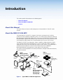
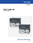
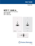
About the MMX 32 VGA MTP
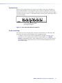
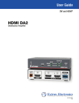
The Extron MMX 32 VGA MTP is a compact, three-input, two-output matrix switcher
suitable for small installations or portable systems. The switcher routes computer video and
both balanced and unbalanced audio signals, and features a bandwidth of 300 MHz (-3 dB)
to accommodate signals of all resolutions, from VGA to UXGA. The switcher/transmitter can
switch computer signals locally or to a remote location up to 750 feet (230 m) away.
The MMX 32 VGA MTP has two outputs. Output 1 provides a video output on a female
15-pin HD connector and an audio output on a 3.5 mm stereo jack. Output 2 provides a
video output on an RJ-45 UTP connector that requires an MTP receiver. The audio output is
summed stereo to mono on the same RJ-45 UTP connector, with an additional
balanced/unbalanced stereo output on a 5-pole captive screw connector.
The switcher can be controlled via the front panel buttons, through remote contact closure,
or by RS-232 control.
Extron
MMX 32 VGA MTP
3x2 VGA Matrix Switcher
with Twisted Pair Output
Document
Camera
Extron
SI 3CT LP
Output 1
3
SE
INP
3
2
1
Output 2
Full-range Ceiling Speaker
with Low Profile Back Can
CT
LE
UT
2
1
CT
LE
UT
INP
SE
Extron
MMX 32 AAP
Extron
SPK 16 Plenum
Controllers
OTE
REM
IO
IO
AUD
SYNC - TRI
PRE PEAK - ON
3
+5V
1
2
3
CONTACT
1
T2
TPU
DIO
AU
R
UT
1
AUD
Rx
2
L
UD
B/A
RG
Extron
MTP RL 15HD A
IO
AUD
INP
T1
TPU
OU
IO
AUD
ER
POW
12V MAX
0.5A
UT
16 AWG Plenum Rated
Speaker Cable
232
RS-
Tx
OU
UT
INP
IO
2
INP
Twisted Pair
Receiver
V
-70
A 401
MP
NG
WIRIUND
S2
!
GRO
RT
CLAS
NOTSHO PUTS
DO OR OUT
A
KER
50m
US
®
UTS
INP
D
SPEA
10V
LISTE O
17TT
/VIDE
ATUS
AUDIO
APPAR
PUT
OUT
MUTE
VOL/
70V
NO)
OTE
(MO
REM
R
L
NO)
L (MO
ER
POW
R
H SYNC +
V SYNC +
C SYNC
SOG
VIDEO
SPARE
12V MAX
1.5A
O
IO
AUD2
MON
1
ON
MT
RL
P
R
WE
PO
15
HD
INP
UT
A
D
RE
FFE T
BU TPU
OU
1
OU
TPU
2
3
4
5
6
T
Mono Power
Amplifier
X
12V MA
.5A
Podium
Computer
Local Monitor
with Audio
Extron
Laptop
Extron
MPA 401
Enhanced Skew Free
A/V UTP Cable
Maximum Distance
XGA: 500’ (150m)
UXGA: 300’ (90m)
Projector
Figure 1. Typical MMX 32 VGA MTP Application
MMX 32 VGA MTP • Introduction
1
Features
•
Inputs — The MMX VGA MTP has three female 15-pin HD input connectors, each with
a 3.5 mm stereo jack.
•
Outputs — The unit routes computer video and audio signals to two outputs:
•
Output 1 is a local output, using one female 15-pin HD connector with a 3.5 mm
stereo jack.
•
Output 2 is a transmitted output, using an RJ-45 UTP connector for RGBHV video
and summed audio, with an additional audio output on a 5-pole captive screw
connector.
•
Stereo audio — The unbalanced stereo audio input can be output as either balanced or
unbalanced stereo audio, or it can be output as dual mono audio.
•
Bandwidth — The switcher features 300 MHz (-3 dB) bandwidth to accommodate any
signal resolution.
•
Peaking option — To compensate for signal loss due to long distance transmission, the
MMX 32 VGA MTP offers DIP switch selectable peaking capability.
•
Bi-level/tri-level sync — Output 2 is compatible with virtually any sync signal. Bi-level
or tri-level sync transmission is DIP switch selectable.
•
Front panel control — Each output has a set of input selector buttons and LEDs for
easy input selection.
•
Remote control — Operate the switcher via optional contact closure and RS-232
remote controllers.
•
Portability — The switcher is light and compact, with rubber feet for tabletop
operation.
•
Rack and furniture mounting — The MMX 32 VGA MTP can be mounted on a rack
shelf or under a desk or podium.
•
Power — An external 12 VDC power connector is included with the switcher.
•
Optional accessory compatibility — The MMX 32 VGA MTP is compatible with
MMX 32 AAP and MMX 32 MAAP contact closure panels. See the application diagram
(figure 23) on page 23.
•
Additional accessories — Extron twisted pair receivers—MTP U series and
MTP RL 15HD A (sold separately)—are required for use with the MMX 32 VGA MTP for
output 2. See the application diagram (figure 1) on page 1.
MMX 32 VGA MTP • Introduction
2
Installation and
Operation
This section covers the following topics:
•
Mounting the MMX 32 VGA MTP
•
Rear Panel Features and Cabling
•
Front Panel Features and Operation
Mounting the MMX 32 VGA MTP
The MMX 32 VGA MTP can be set on a table, mounted on a rack shelf, or mounted under a
desk, podium, or tabletop.
Tabletop Use
Four self-adhesive rubber feet are included with the switcher. For tabletop use, attach one
foot at each corner of the bottom of the unit, and place the unit in the desired location.
UL Requirements for Rack Mounted Devices
The following Underwriters Laboratories (UL) requirements pertain to the safe installation of
the MMX in a rack.
1. Elevated operating ambient temperature — If the equipment is installed in a closed
or multi-unit rack assembly, the operating ambient temperature of the rack environment
may be greater than room ambient temperature. Therefore, install the equipment in an
environment compatible with the maximum ambient temperature
(Tma = +122 °F, +50 °C) specified by Extron.
2. Reduced air flow — Install the equipment in a rack so that the amount of air flow
required for safe operation of the equipment is not compromised.
3. Mechanical loading — Mount the equipment in the rack so that a hazardous condition
is not achieved due to uneven mechanical loading.
4. Circuit overloading — Connect the equipment to the supply circuit and consider the
effect that circuit overloading might have on overcurrent protection and supply wiring.
Appropriate consideration of equipment nameplate ratings should be used when
addressing this concern.
5. Reliable earthing (grounding) — Maintain reliable grounding of rack-mounted
equipment. Pay particular attention to supply connections other than direct connections
to the branch circuit (e.g. use of power strips).
MMX 32 VGA MTP • Installation and Operation
3
Rack Mounting
For optional rack mounting, mount the switcher on any of the following rack shelves:
•
RSU 126, 6” deep 1U rack shelf kit (part number 60-190-10)
•
RSB 126, 6” deep basic 1U rack shelf (part number 60-604-10)
•
RSU 129, 9.5” deep Standard universal 1U rack shelf kit (part number 60-190-01)
•
RSB 129, 9.5” deep Basic universal 1U rack shelf (part number 60-604-01)
On the standard rack shelf, the switcher mounts in one of four locations to the rear of the
rack or in one of four locations to the front of the rack. To rack mount a MMX 32 VGA MTP,
do the following:
1. Remove rubber feet if they were previously installed on the bottom of the switcher.
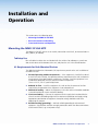
2. Mount the switcher on the rack shelf, using two 4-40 x 3/16 inch screws in opposite
(diagonal) corners to secure it to the shelf (see figures 2 and 3 below).
3. Install blank panels or other units on the rack shelf.
4. Attach the rack shelf to the rack using the supplied bolts.
6" Deep Rack Shelf
1/2 Rack Width Front False
Faceplate
Front false
faceplate
uses 2
screws.
(2) 4-40 x 3/16"
Screws
Use 2 mounting holes
on opposite corners.
Figure 2. Mounting the MMX 32 VGA MTP on a 6 Inch Rack Shelf
1U Universal Rack Shelf
1/2 Rack Width Front False
Faceplate
Front false
faceplate
uses 2
screws.
(2) 4-40 x 3/16"
Screws
Use 2 mounting holes
on opposite corners.
NOTE: Using screws longer
than 3/16” will damage the
unit and void the warranty.
Figure 3. Mounting the MMX 32 VGA MTP on a Standard Rack Shelf
MMX 32 VGA MTP • Installation and Operation
4
Furniture Mounting
Use the optional MBU 125 mounting kit (part number 70-077-01) to mount the MMX as
follows:
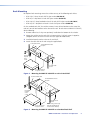
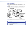
1. Remove the feet from the bottom of the MMX, if installed.
2. Attach the mounting brackets to the MMX with the provided machine screws
(figure 4).
Figure 4.
Mounting the MMX 32 VGA MTP Under Furniture
3. Hold the device with the attached brackets against the underside of the mounting
surface. Mark the bracket screw hole locations on the mounting surface.
4. Drill 3/32 inch (2 mm) diameter pilot holes, 1/4 inch (6.3 mm) deep in the mounting
surface at the marked locations.
5. Insert #8 wood screws into the pilot holes. Tighten the screws until just less than
1/4 inches of the head protrudes.
6. Align the mounting screws with the slots in the brackets and place the MMX against the
surface, with the screws through the bracket slots.
7. Slide the device slightly forward or back, then tighten all four screws to secure it in
place.
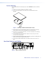
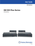
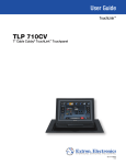
Rear Panel Features and Cabling
AUDIO
INPUT 3
OUTPUT 2
AUDIO
1
1
AUDIO
L
2
3
R
+5V
CONTACT
RGB/AUDIO
POWER
12V
0.5A MAX
REMOTE
SYNC - TRI
PRE PEAK - ON
INPUT 1
RS-232
2
AUDIO
9
1
OUTPUT 1
2
Tx Rx
BI
OFF
INPUT 2
AUDIO
3
4
6
5
7
8
Figure 5. MMX 32 VGA MTP Rear Panel
MMX 32 VGA MTP • Installation and Operation
5
Inputs
a Video and audio inputs — Connect computer video sources to these female 15-pin
HD connectors. Connect audio sources to these 3.5 mm stereo jacks. Wire the audio
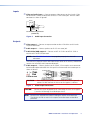
connectors as shown in figure 6.
Tip (L)
Ring (R)
Sleeve ( )
3.5 mm Stereo Plug Connector
(unbalanced)
Figure 6.
Audio Input Connection
Outputs
b Video output 1 — Connect an output monitor or other VGA device to this female
15-pin HD connector.
c Audio output 1 — Connect speakers to this 3.5 mm stereo jack.
d Audio/Video (RGB) output 2 — Connect an MTP R 15 HD A or MTP RL 15HD A
receiver to this RJ-45 UTP connector.
NOTE: See “TP Cable Termination” on page 9 to properly wire the RJ-45
connectors.
Then connect a projector or other RGB video output device to the receiver, and connect
speakers for summed (L and R) mono audio output.
e Audio output 2 — Connect speakers to this 5-pole, 3.5 mm captive screw connector
for balanced/unbalanced audio. Wire the captive screw connector for stereo output as
shown in figure 7.
CAUTION:
Figure 7.
CAUTION:
For unbalanced audio, connect both sleeves to the center (ground)
contact. DO NOT connect the sleeves to the negative (-) contacts.
Audio Output Connections
Connect the sleeve to ground (Gnd). Connecting the sleeve to a negative
(-) terminal will damage the audio output circuits.
NOTE: Do not tin the stripped wires before installing the captive screw connector.
Tinned wires are not as secure in the captive screw connectors and could be
pulled out.
MMX 32 VGA MTP • Installation and Operation
6
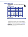
f Pre-peaking selection — To select the correct peaking option to compensate
for signal loss over long cable runs, set the DIP switch position as shown in the
table below:
Video
Format
Pre-Peak
off
Pre-Peak
on
Composite,
S-video,
Component
BI
OFF
Pre-peaking settings table
SYNC - TRI
PRE PEAK - ON
Pre-Peaking and Sync Selection
Max. distance Max. distance
(high quality) (variable quality)
800 ft.
(245 m)
1000 ft.
(300 m)
640 x 480
<300 ft.
(90 m)
<350 ft.
(105 m)
700 ft.
(215 m)
750 ft.
(240 m)
800 x 600
<300 ft.
(90 m)
<350 ft.
(105 m)
550 ft.
(165 m)
650 ft.
(200 m)
1024 x 768
<300 ft.
(90 m)
<350 ft.
(105 m)
500 ft.
(150 m)
600 ft.
(185 m)
1280 x 1024
<250 ft.
(75 m)
<300 ft.
(90 m)
350 ft.
(105 m)
450 ft..
(135 m)
1600 x 1200
<250 ft.
(75 m)
<300 ft.
(90 m)
300 ft.
(90 m)
450 ft.
(135 m)
Sync selection — To select either bi-level sync or tri-level sync on output 2, set the sync DIP
switch to the desired setting.
NOTE: Set when transmitting tri-level sync component video.
Remote Control Connections
g Contact closure connectors — These two 5-pole captive screw connectors provide
remote contact closure control of outputs 1 and 2 by connecting an Extron MMX 32
AAP (part number 70-277-11) or MMX 32 MAAP (part number 70-277-12, or -22)
contact closure remote control panel. Connect the 5 V and Gnd (-) 2-pole captive screw
connector on the AAP or MAAP to either of these connectors. See “Remote Control”
on page 12 for more information.
h RS-232 connector — Connect an RS-232 control module to this 3-pole captive screw
connector to allow remote control using the Extron Simple Instruction Set (SIS™) or the
Extron Universal Switcher Control Program.
MMX 32 VGA MTP • Installation and Operation
7
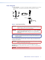
Power Connection
i Power connector — An external 12 VDC power supply is included with the unit. Plug it
into this 2-pole 3.5 mm captive screw connector. Wire the connector as shown in
figure 8.
G
Smooth
Ridges
A
A
SECTION A–A
Power Supply
Output Cord
Tie Wrap
Figure 8. Power Connection Wiring
CAUTION:
Power supply voltage polarity is critical. Incorrect voltage polarity can
damage the power supply and the MMX. Identify the power cord negative
lead by the ridges on the side of the cord (figure 8).
CAUTION:
The length of the exposed (stripped) copper wires is important. The ideal
length is 5/16 inches (7 mm). Longer bare wires can short together.
Shorter wires are not as secure in the captive screw connectors and could
be pulled out.
NOTE: Do not tin the stripped power supply leads before installing the captive screw
connector. Tinned wires are not as secure in the captive screw connectors and
could be pulled out.
To verify the polarity before connection, plug in the power supply with no load and check
the output with a voltmeter.
WARNING: The two power cord wires must be kept separate while the power supply is
plugged in. Remove power before wiring.
As an alternative, an Extron P/S 123 Universal 12 V DC Power Supply, part number
60-814-01, can power multiple MMXs or other Extron 12 V DC devices, using only one AC
power connector.
CAUTION:
Do not daisy chain power to this unit.
MMX 32 VGA MTP • Installation and Operation
8
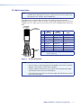
TP Cable Termination
NOTE: RJ-45 termination must comply with the TIA/EIA T 568A or TIA/EIA T 568B wiring
standards for all connections. If you are using Skew-Free™ A/V UTP cable, then
you should use the TIA/EIA T 568A standard only.
Figure 9 details the recommended termination of TP cables with RJ-45 connectors in
accordance with the TIA/EIA T 568A or TIA/EIA T 568B wiring standards. You can use either
standard with CAT 5 cable, but ensure that you use the same standard on both ends of the
cable.
Clip Down
Pins 1 2 3 4 5 6 7 8
RJ-45
connector
568 A
Wire color
Pin
12345678
Twisted
Pairs
1&2
Signal
1
White-green
White-orange
Red+/V. sync+
2
Green
Orange
Red-/V. sync-
3
White-orange
White-green
Mono audio+
4
Blue
Blue
Green+
5
White-blue
White-blue
Green-
6
Orange
Green
Mono audio-
7
White-brown
White-brown
Blue+/H. sync+
8
Brown
Brown
Blue-/H. sync-
NOTE:
7&8
568 B
Wire color
If you use Skew-Free™ A/V cable, use the TIA/EIA T
568A standard only.
3&6 4&5
Figure 9. TP Cable Termination
NOTES: • Skew-Free A/V cable is not recommended for Ethernet/LAN applications.
• Skew-Free cable is specially designed for compatibility with Extron Twisted Pair
products, wired using the TIA/EIA 568 A standard.
• The green, brown, and blue pairs of this cable have virtually identical lengths
and should be used to transmit the RGB signals.
• The orange pair of this cable has a different length and should not be used to
transmit the RGB signals.
MMX 32 VGA MTP • Installation and Operation
9
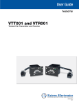
Front Panel Features and Operation
OUTPUT 1
1
2
OUTPUT 2
3
1
2
3
MMX 32 VGA MTP
1
2
Figure 10.Front Panel Features
a Input selector buttons and LEDs for output 1 — Press the button corresponding to
the desired input. The LED for that input lights.
b Input selector buttons and LEDs for output 2 — Press the button corresponding to
the desired input. The LED for that input lights.
NOTE: When power is applied, the LEDs light sequentially from left to right. For first
time power up, the default configuration of the unit is input 1 tied to both
outputs 1 and 2, so that the input 1 LEDs for both output 1 and for
output 2 are lit. If this is not a first time power up, then the LEDs
corresponding to the last valid input selections light.
NOTE: Tying input 0 to an output is done only using RS-232, and it is reflected on
the front panel and any optional MMX 32 AAP/MAAP installed. When a tie
is made between an input and an output, if that output was previously tied
to another input, the older tie is broken when the new input is selected.
NOTE: Audio breakaway is done by RS-232 through the Extron Simple Instruction
Set (SIS) or the Universal Switcher Control Program. The LED corresponding
to the audio source flashes during breakaway.
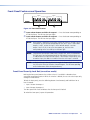
Front Panel Security Lock Out (executive mode)
Locking the front panel protects the switcher when it is installed in a location where
unwanted tampering may occur. While the switcher is locked, the user can select inputs only
through a remote device.
To lock the front panel, press the following buttons simultaneously and hold them for at
least 3 seconds:
•
Input 1 button for output 1
•
Input 3 button for output 2
The front panel LEDs flash to indicate that the front panel is locked.
To unlock the front panel, repeat this procedure.
MMX 32 VGA MTP • Installation and Operation
10
System Reset
To clear all user settings and reset the switcher to its factory settings, press and hold the
input 3 button for output 1 while you power up the switcher (see figure 11). Continue to
hold the button while the switcher lights the front panel LEDs sequentially from left to right.
The default settings are: input 1 is tied to both outputs, the front panel is not locked, and all
states are unmuted.
OUTPUT 1
1
2
OUTPUT 2
3
1
2
3
MMX 32 VGA MTP
Press and hold this button while
powering up the switcher.
Figure 11.Press and Hold to Reset the Switcher
Audio Switching
When you select an input by pressing a front panel selector button, the audio and video
signals from that input are routed together to the appropriate output.
•
The MMX 32 VGA MTP also features audio breakaway through the Extron Simple
Instruction Set or the Extron Universal Switcher Control Program (see “Remote
Control” on page 12 for details). When audio breakaway is active, the front panel LED
corresponding to the audio source flashes, while the LED corresponding to the video
source lights steadily.
MMX 32 VGA MTP • Installation and Operation
11
Remote Control
This section covers topics relating remote control operation, including:
•
Output Control
•
RS-232 Control
•
Contact Closure Control
The rear panel Remote connectors of the switcher can be connected to the serial port output
of a host device such as a computer or control system, or to a contact closure device such
as the Extron MMX 32 AAP panel (part number 70-277-11) or MMX 32 MAAP panel (part
number 70-277-12 or -22). The contact closure connectors are two 5-pole captive screw
connectors, which control outputs 1 and 2 separately.
Output 1 control
REMOTE
1
2
3
+5V
CONTACT
1
RS-232
2
RS-232
connection
Tx Rx
Output 2 control
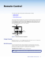
Figure 12.Remote Connectors Arrangement
Output Control
Momentarily short pin 1, 2, or 3 to ground to switch to that input. Use the +5 V port when
controlling the output with an MMX 32 AAP/MAAP panel.
RS-232 Control
The RS-232 connection makes software control of the switcher possible via the Extron
Simple Instruction Set (SIS) or the Extron Windows®-based control program. The RS-232
connector on the MMX 32 VGA MTP is a 3-pole captive screw connector.
The protocol for this connector is:
•9600 baud •8-bit •1 stop bit •no parity •no flow control
NOTE: For RS-232 connect transmit, receive, and ground connectors to control system
or PC.
MMX 32 VGA MTP • Remote Control
12
Simple Instruction Set Control
Host-to-switcher instructions
The switcher accepts SIS commands through the remote connector. SIS commands consist
of one or more characters per command field. They do not require any special characters to
begin or end the command character sequence. Each switcher response to an SIS command
ends with a carriage return and a line feed (CR/LF = ), which signals the end of the
response character string. A string is one or more characters.
Switcher-initiated message
The following copyright message is initiated by the switcher when it is first powered on.
Vx.xx is the latest firmware version number.
(c) Copyright 2005, EXTRON ELECTRONICS
“MMX 32 VGA MTP”, Vx.xx
Switcher error responses
When the switcher receives an SIS command and determines that it is valid, it performs the
command and sends a response to the host device. If the switcher is unable to perform
the command because the command is invalid or contains invalid parameters, the switcher
returns an error response to the host. The error response codes are:
E01 — Invalid input channel number (out of range)
E10 — Invalid command
E12 — Invalid output number (out of range)
E13 — Invalid value (out of range)
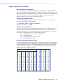
Using the command/response table
The SIS command/response table begins on the next page. Lower case letters are acceptable
in the command field only where indicated(B/b, for example). Symbols are used throughout
the table to represent variables in the command/response fields. Symbol definitions and an
ASCII-to-hexadecimal (HEX) conversion table are provided below. Command and response
examples are shown throughout the tables.
ASCII to HEX Conversion Table
Esc 1B CR ØD LF
ØA
2Ø
!
21
“ 22 # 23 $ 24 %
25 &
26
‘
27
28
)
29
* 2A + 2B ,
2C -
2D .
2E
/
2F
3Ø 30
1
31
2 32 3 33 4 34 5
35 6
36
7
37
8
38
9
39
:
3B < 3C =
3D >
3E
?
3F
@
40
A
41
B 42 C 43 D 44 E
45 F
46
G
47
H
48
I
49
J
4C M
4D N
4E
O
4F
P
5Ø Q
51
R 52 S
53 T
54 U
55 V
56
W
57
X
58
Y
59
Z 5A [
5B \
5C ]
5D ^
5E
-
5F
`
6Ø
a
61
b 62 c
63 d 64 e
65 f
66
g
67
h
68
i
69
j
6A k
6B l
6C m
6D n
6E
o
6F
p
7Ø
q
71
r
72 s
73 t
74 u
75 v
76
w
77
x
78
y
79
z
7A {
7B l
7C }
7D ~
7E
DEL 7F
(
3A ;
4A K 4B L
MMX 32 VGA MTP • Remote Control
13
Symbol definitions
•
= Space
] = Carriage return/line feed
} = Carriage return (no line feed)
E = “Escape key” or W
|
= Pipe (vertical bar) character. Has the same function as }.
W
= Has the same function as E.
X!
X@
X#
X(
X1(
X2)
= Input number
1–3
= Input number (for tie)
0 – 3, 0 = disconnected
= Output number
1 or 2
= Mute/lock
0 = off/unlocked, 1 = on/locked
= Controller software version number to second decimal place
= Audio/Video mute status 0 = no mute, 2 = audio mute
1 = video mute, 3 = video and audio mute
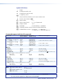
Command/response table for SIS commands
Command
(host to switcher)
ASCII Command Response
(switcher to host)
Additional description
Tie input X@ to output X#, A & V
Example:
X@*X# !
1*2!
OutX#•InX@•All]
Out02•In01•All]
Tie input 1 audio and video to output 2.
Tie input X@ RGB to output X#
Example:
X@*X# %
3*1%
OutX#•InX@•RGB]
Out01•In3•RGB]
Tie input 3 RGB to output 1.
Tie input X@ audio to output X#
Example:
X@*X#$
1*2$
OutX#•InX@•Aud]
Out02•In1•Aud]
Tie input 1 audio to output 2.
RGB mute
X#*1B/b
VmtX#*1]
Mute RGB output X#.
RGB unmute
X#*0B/b
VmtX#*0]
Unmute RGB output X#.
Read RGB mute
X# B/b
X(]
Show RGB mute status
Create ties
RGB mute
Global (Where X# is not included, global RGB mute is activated.)
RGB mute all
1*B/b
Vmt1]
RGB unmute all
0*B/b
Vmt0]
X9
(0 = off and 1 = on).
Mute all RGB.
Unmute all RGB.
Audio mute
Audio mute
X#*1Z/z
AmtX#*1]
Mute audio output X#.
Audio unmute
X#*0Z/z
AmtX#*0]
Unmute audio output X#.
Read audio mute
X#Z/z
X(]
Show audio mute status X( (0 = off and 1 = on).
Global (Where X# is not included, global Audio mute is activated.)
Audio mute all
1*Z/z
Amt1]
Audio unmute all
0*Z/z
Amt0]
NOTE:
Mute all audio.
Unmute all audio.
X@ = Input number (for tie)
0 – 3
0 = disconnected
X# = Output number 1 or 2
X( = Mute status
0 = off
1 = on
NOTES:• Tie commands can be made back-to-back with no spaces. Example: 1*1!02!03*03!...
• The matrix switcher supports the 2-digit numeric format (01*02).
MMX 32 VGA MTP • Remote Control
14
Command
ASCII Command
Response
Additional description
Lock front panel
1 X/x
Exe1]
Lock front panel.
Unlock front panel
0 X/x
Exe0]
Unlock front panel.
Lock status
X/x
X(]
Show lock status (0 = unlocked and 1 = locked)
System reset (factory default)
EZXXX}
Zpx]
Clear all ties and unmute audio and video.
Unmute RGB
EZZ}
Zpz]
Unmute all.
View RGB output tie
Example:
X#%
2%
X@]
3]
Output 2 video is tied to input 3 video.
View audio output tie
Example:
X#$
1$
X@]
2]
Output 1 audio is tied to input 2 audio.
Output mute
X#VM
X2)]
(host to switcher)
(switcher to host)
Front panel security lock out
Reset to factory defaults
View ties and output mute
Output mute X2) (0 = no mute, 1 = video
mute, 2 = audio mute, 3 = video and audio
mute).
“VM” must be upper case
Information requests
Information request
I/i
Example:
i
V1*X@•A1*X@•V2*X@•A2*X@•Vmt1*X(•Amt1*X(•Vmt2*X(•Amt2
*X(]
V1*1•A1*1•V2*2•A2*2•Vmt1*0•Amt1*0•Vmt2*0•Amt2*0
ab c d
See note below for
explanation
Request part number
N/n
xx-xxx-xx]
60-565-01 = MMX 32 VGA MTP switcher.
Query firmware version
Q/q
X1(]
Show firmware version number.
NOTES: X@ = Input number (for tie)
0–3
0 = disconnected
X# = Output number 1 or 2
X( = Lock status
0 = unlocked
1 = locked
X1( = Controller software version number to second decimal place
X2) = Mute 0 = no mute 2 = audio mute
1 = video mute 3 = video and audio mute
a Input 1 supplies video and audio for output 1.
b Input 2 supplies video and audio for output 2.
c Output 1 does not mute video or audio.
d Output 2 does not mute video or audio.
MMX 32 VGA MTP • Remote Control
15
Loading firmware using an SIS command
Firmware can be uploaded two ways:
1. Using the Universal Switcher Control Program.
2. Using the “Eupload” SIS command entered via a communications utility such as
HyperTerminal.
NOTE: Extron recommends that you upload firmware using the Universal Switcher
Control Program (see “Updating the firmware” on page 21) and reserve this
SIS procedure for correcting firmware that has been corrupted and is unable to
respond to the Universal Switcher Control Program.
Firmware can be loaded using SIS commands as follows:
1. Visit the Extron Web site, www.extron.com, select the MMX switcher product
category, select the latest firmware file for download, and run the executable file. This
installs the firmware to your computer. Follow the instructions on the screen. Note the
folder where the firmware file is saved.
2. Start a communications utility such as HyperTerminal. Select the Com port that is
connected to the switcher’s RS-232 port. Use 9600 bits per second, 8 data bits, no
parity, 1 stop bit, and no flow control.
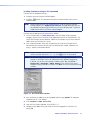
NOTE: If you are performing this procedure to recover from corrupted firmware, the
switcher responds only to the “n”, “q”, and “Eupload” SIS commands.
NOTE: The firmware upload can take several minutes. If the HyperTerminal echo
function is turned off, there is no indication that the upload is progressing.
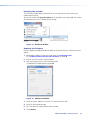
If desired, turn on the echo function as follows (figure 13): Select File >
Properties > Settings > ASCII Setup. Ensure that the Echo typed
characters locally check box is checked. Click OK on the ASCII Setup and Settings
windows.
Figure 13.Turn on the Echo Function
3. Press and release the Esc key on the keyboard and then type upload. The computer
responds with the “Go” prompt.
4. Click Transfer > Send text file.
5. From the Files of type: drop box, select All files (*.*).
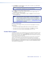
6. Navigate to the folder where you saved the firmware upgrade file. Select the file
(figure 14).
MMX 32 VGA MTP • Remote Control
16
NOTE: Ensure that the firmware upgrade is for the MMX Series switcher. Valid firmware
files must have the file extension “.s19”. Any other file extension is not a
firmware upgrade for your switcher.
7. Click Open. The firmware upload begins. If the HyperTerminal echo function is turned
on, HyperTerminal displays a scroll of the text of the firmware file as it uploads to the
switcher (figure 15).
Figure 14.Select the Firmware Upgrade File
Figure 15.Upload Progress Display
8. After several minutes, the switcher reports the start-up copyright message:
(c) Copyright 2005, EXTRON ELECTRONICS
“MMX 32 VGA MTP”, Vx.xx ]
This message indicates that the firmware upload is complete.
9. Exit HyperTerminal.
MMX 32 VGA MTP • Remote Control
17
Windows®-Based Control Program
The Universal Switcher Control Program is compatible with Windows 98 and later, and
provides remote control of the input selection for each output (including video/audio
breakaway), audio gain and attenuation adjustments, and front panel lock out.
Updates to this program can be downloaded from the Extron Web site
(www.extron.com).
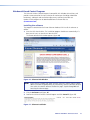
Installing the software
The program is contained on the Extron Software Products DVD. Install the software as
follows:
1. Insert the DVD into the drive. The installation program should start automatically. If it
does not self-start, run Launch.exe from the DVD.
The Extron software DVD window appears (figure 16).
Figure 16.Software DVD Window
NOTE: Either select the product tab (page) and then select the switcher from the dropdown list or from the group names; or, alternatively, select the software tab and
then select the switcher software listed on the page. Steps 2 through 4 detail
accessing the software page.
2. Click the Software tab (figure 16).
3. Scroll to the Universal Switcher Control Program and click Install (figure 17).
Figure 17.Software Installation
MMX 32 VGA MTP • Remote Control
18
4. Follow the on-screen instructions. The program prompts you to choose to either “run”
or “save” the software. Click Run for the default installation, which creates a
C:\Program Files\Extron\UNIVSW folder and places three files (UNIVSW.exe,
UNIVSW.hlp, and UniversalSwitch_update.exe) into the folder. A shortcut for the Control
Program may also be placed on the PC Desktop for quick access.
Click Save if you want to save the software installer on your PC.
NOTE: In some installations, you may be prompted to restart your PC before you can
use the software.
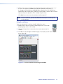
Using the software
To run the software after it has been installed, follow these steps:
1. Double-click the Universal Switcher Control Program icon in the Extron
program group, or on the PC Desktop.
2. Click the COM port that is connected to the remote connector of the
switcher.
3. Click OK. The Control Program window displays the selected inputs for each
output (figure 18).
Figure 18. Universal Switcher Control Program Window
MMX 32 VGA MTP • Remote Control
19
Resetting the switcher
The Unit Reset window allows you to clear all user settings and reset the switcher to its
factory default settings.
To reset the switcher, click System Reset on the Configure menu (figure 19). The switcher
will automatically reset to its factory default settings.
Figure 19. Unit Reset Window
Updating the firmware
Firmware updates periodically become available on the Extron Web site. To load a firmware
update:
1. Download the update file from the Extron Web site (www.extron.com).
See “Loading Firmware Using an SIS Command” on page 16.
2. Run the Universal Switcher Control Program.
3. From the Configure menu, select Firmware Loader.
The Add Device window appears (figure 20).
Figure 20. Add Device Window
4. Select the device—MMX 32 VGA MTP—in the Device Name field.
5. Select the Connection Method.
6. Fill in the Com Port and Baud Rate fields if needed.
7. Click Connect.
MMX 32 VGA MTP • Remote Control
20
8. Click Browse in the New Firmware File field. Locate the update file you downloaded
from the Web site and click Open.
NOTE: The firmware update file must have an .s19 extension. If it does not have
that extension, it could cause the unit to stop functioning.
9. Click Add. The Firmware Loader window will appear.
10.Click Begin on the upper right hand corner of the Firmware Loader window. The
program will begin to load the update.
11.When the program is finished loading the update, click Exit. The Universal Switcher
Control Program closes.
NOTE: If the firmware loader utility exits before the status bar has progressed
completely across the indicator window, the firmware may be corrupted
and may no longer respond to the Universal Switcher Control Program or
the Firmware Loader utility. In this condition, the firmware upload can be
accomplished only by using SIS commands. See “Loading Firmware Using
an SIS Command” on page 16.
Using the help system
For information about program features, you can access the help program in any of the
following ways:
•
From the Extron program group, double-click the Universal Switcher Help icon.
•
From within the Universal Switcher Control Program, click Help on the task bar.
•
From within the Universal Switcher Control Program, press the F1 key.
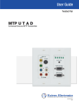
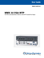
Contact Closure Control
The MMX 32 VGA MTP can be controlled remotely using the optional Extron MMX 32 AAP
contact closure control panel (part number 70-277-01, -11, or -21) or the MMX 32 MAAP
contact closure panel (part number 70-277-12 or -22). Each panel controls one output and
has three input selector buttons and LEDs.
The contact closure system uses the two 5-pole captive screw connectors, which control
outputs 1 and 2 separately. Each contact closure pin corresponds to an input/output
connection, or tie. A tie is made when one pin is momentarily connected to ground. Each
pin returns a signal to the remote control panel after a tie is made, lighting the control panel
LED corresponding to the selected input. A +5 V port is used when controlling the output
with an MMX 32 AAP/MAAP panel.
MMX 32 VGA MTP • Remote Control
21
Connecting an MMX 32 AAP or MMX 32 MAAP Control Panel
Each Extron MMX 32 AAP and MMX 32 MAAP contact closure remote control panel can
control one of the two outputs on the switcher.
To connect a panel to the switcher, wire the captive screw connectors on the rear of the
panel as follows:
3
4
2
5
1
Figure 21.MMX 32 AAP Rear Panel
3
4
5
2
1
Figure 22.MMX 32 MAAP Rear Panel
Input selection connector
1 pole — Connect this pole of the captive screw connector to pin 1 of the captive
aInput
screw connector on either output 1 or output 2 on the MMX 32 VGA MTP Remote.
2 pole — Connect this pole of the captive screw connector to pin 2 of the captive
bInput
screw connector on either output 1 or output 2 on the MMX 32 VGA MTP Remote.
3 pole — Connect this pole of the captive screw connector to pin 3 of the captive
cInput
screw connector on either output 1 or output 2 on the MMX 32 VGA MTP Remote.
MMX 32 VGA MTP • Remote Control
22
Contact closure connectors
pole — Connect this pole of the captive screw connector to the 5 VDC pole of
d5theVDC
captive screw connector on either output 1 or output 2 on the MMX 32 VGA MTP
Remote.
pole — Connect this pole of the captive screw connector to the ground pole of
eGND
the captive screw connector on either output 1 or output 2 the MMX 32 VGA MTP
Remote.
Control
Extron
MMX 32 VGA MTP
Document
Camera
Matrix Switcher
OTE
REM
AUD
O
UDI
B/A
RG
SYNC - TRI
PRE PEAK - ON
3
+5V
1
2
3
CONTACT
1
T2
TPU
RS-
Tx
OU
IO
UT
INP
IO
AUD R
Audio System
232
Rx
2
L
IO
UT
1
AUD
IO
AUD
INP
T1
TPU
OU
IO
AUD
UT
2
INP
MT
O
IO
AUD2
MON
1
P
R
15
ON
1
R
WE
PO
12V MAX
.5A
3
2
INP
T
UT
TPU
OU
HD
H SYNC +
V SYNC +
C SYNC
SOG
VIDEO
SPARE
ER
POW
12V MAX
0.5A
2
3
4
5
6
A
Extron
MTP RL 15HD A
Twisted Pair
Receiver
CT
LE
T SE
INPU
1
Extron
AAP 102 w/
MMX 32 AAP
Podium
Computer
LCD Monitor
with Audio
Laptop
Projector
Extron
Enhanced Skew Free
A/V UTP Cable
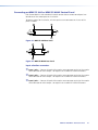
Figure 23.Typical MMX 32 VGA MTP Application Using Contact Closure Remote
Control
NOTE: Only one MMX 32 AAP or MMX 32 AAP control panel can be used to control
each output.
NOTE: Extron recommends shielded twisted pair cable, such as STP 22 dual plenum
cable, number 22-162-03 (or equivalent).
Unsheilded cable can allow crosstalk and interference between the MMX and
the control panel.
MMX 32 VGA MTP • Remote Control
23
Reference
Information
This section covers the following topics:
•
Specifications
•
Part Numbers
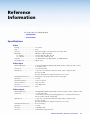
Specifications
Video
Routing������������������������������������������ 3 x 2 matrix
Gain����������������������������������������������� Unity
Protocols���������������������������������������� ARP, ICMP (ping), IP, TCP, UDP, DHCP, HTTP, SMTP, Telnet
Bandwidth������������������������������������� 300 MHz (-3 dB), fully loaded
0 – 10 MHz����������������������������� no more than +0.1 dB to -0.1 dB
0 – 130 MHz��������������������������� no more than +2 dB to -0.1 dB
Crosstalk���������������������������������������� -55 dB @ 10 MHz, -45 dB @ 30 MHz, -37 dB @ 100 MHz
Switching speed����������������������������� 200 ns (max.)
Video input
Number/signal type������������������������ 3 universal multiformat RGBHV, RGBS, RGsB, RsGsBs, component video, S-video,
or composite video
Connectors������������������������������������ (3) 15-pin HD female
Nominal level��������������������������������� 1 Vp-p for Y of component video and S-video, and for composite video
0.7 Vp-p for RGB
0.3 Vp-p and R-Y/B-Y of component video for C of S-video
Minimum/maximum levels�������������� Analog: -0.5 V to 2.0 Vp-p with no offset at unity gain
Impedance������������������������������������� 75 ohms
Horizontal frequency���������������������� 15 kHz to 145 kHz
Vertical frequency��������������������������� 30 Hz to 170 Hz
Return loss������������������������������������� <-42 dB @ 5 MHz
DC offset (max. allowable)������������� 4.0 V
Video output
Number/signal type������������������������ 2 analog RGBHV, RGBS, RGsB, RsGsBs, component video, S-video, composite video
Connectors������������������������������������ (1) 15-pin HD female
1 RJ-45 female (for proprietary analog signals to be received by MTP U R Series,
MTP RL 15HD A, MTP RL 15HD A SEQ)
Nominal level��������������������������������� 1 Vp-p for Y of component video and S-video, and for composite video
0.7 Vp-p for RGB
0.3 Vp-p and R-Y/B-Y of component video for C of S-video
Minimum/maximum levels�������������� 0.3 V to 2.0 Vp-p
Impedance ������������������������������������ 75 ohms
Return loss ������������������������������������ <-30 dB @ 5 MHz
DC offset��������������������������������������� <±20 mV with input at 0 offset
MMX 32 VGA MTP • Reference Information
24
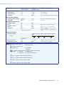
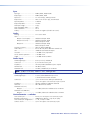
Sync
Input type�������������������������������������� RGBHV, RGBS, RGsB, RsGsBs
Output type����������������������������������� RGBHV, RGBS, RGsB
Input level�������������������������������������� 2.5 V to 5.0 Vp-p, 4.0 Vp-p normal
Output level����������������������������������� AGC to TTL: 4 V to 5 Vp-p, unterminated
Input impedance���������������������������� 510 ohms
Output impedance������������������������� 75 ohms
Max input voltage�������������������������� 5 Vp-p
Max. propagation delay������������������ 30 ns
Max. rise/fall time��������������������������� 4.2 ns
Polarity������������������������������������������� Positive or negative (selectable at receiver)
Audio
Routing ����������������������������������������� 3 x 2 stereo matrix
Gain����������������������������������������������� Output 1 (local output)������������ Unbalanced output: 0 dB
Output 2a (reciever)����������������� Unbalanced output: 0 dB;
balanced output: +6 dB
Output 2b������������������������������� Unbalanced output: 0 dB;
balanced output: +6 dB
Frequency response������������������������ 20 Hz to 20 kHz, ±0.05 dB
THD + Noise����������������������������������� 0.15% @ 1 kHz, 0.3% @ 20 kHz nominal level
S/N������������������������������������������������� >90 dB at rated maximum output
Crosstalk���������������������������������������� <-76 dB @ 1 kHz, fully loaded
Stereo channel separation�������������� >-76 dB @ 1 kHz
CMRR�������������������������������������������� >-75 dB @ 20 Hz to 20 kHz
Audio input
Number/signal type������������������������
Connectors������������������������������������
Impedance�������������������������������������
Nominal level���������������������������������
Maximum level ������������������������������
3 stereo, PC level, unbalanced
(3) 3.5 mm mini stereo jacks
>3k ohms, balanced/unbalanced, AC coupled
-10 dBV (316 mV)
+8.5 dBu, (unbalanced) at 1%THD+N
NOTE: 0 dBu = 0.775 Vrms, 0 dBV = 1 Vrms, 0 dBV
2 dBu
Audio output
Number/signal type������������������������ 2 stereo, balanced/unbalanced, PC level
1 summed stereo-to-mono on RJ-45
Connectors������������������������������������ (1) 3.5 mm mini stereo audio jack (unbalanced)
(1) 3.5 mm captive screw connector 5-pole (1) RJ-45
Impedance������������������������������������� 50 ohms unbalanced, 100 ohms balanced
Gain error�������������������������������������� ±0.1 dB channel to channel
Maximum level (Hi-Z)
Output 2��������������������������������� >+17 dBu, balanced or unbalanced at 1%THD+N
Maximum level (600 ohm)
Output 2��������������������������������� >+14 dBm, balanced or unbalanced at 1%THD+N
Control/remote — switcher
Serial control port �������������������������� RS-232, 3.5 mm captive screw connector, 3 pole
Baud rate and protocol ������������������ 9600 baud, 8 data bits, 1 stop bit, no parity
Serial control pin configurations����� 1 = TX, 2 = RX, 3 = GND
Contact closure������������������������������ (2) 3.5 mm captive screw connector, 5 pole
MMX 32 VGA MTP • Reference Information
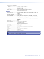
25
Contact closure pin configurations
Output 1:�������������������������������� 1= input 1, 2 = input 2, 3 = input 3,
4 = GND, 5 = 5 VDC
Output 2:�������������������������������� 1= input 1, 2 = input 2, 3 = input 3,
4 = GND, 5 = 5 VDC
Program control����������������������������� Extron control/configuration program for Windows®
Extron Simple Instruction Set (SIS™)
General
External power supply�������������������� 100 VAC to 240 VAC, 50/60 Hz, external, autoswitchable; to 12 VDC, 1 A,
regulated
Power input requirements�������������� 12 VDC, 0.7 A
Temperature/humidity�������������������� Storage: -40 to +158 °F (-40 to +70 °C) / 10% to 90%, noncondensing
Operating: +32 to +122 °F (0 to +50 °C) / 10% to 90%, noncondensing
Rack mount������������������������������������ Yes, with optional 1U rack shelf, part number 60-190-01 or 60-604-01; or
number 60-190-10 or number 60-604-10.
Also furniture mountable with optional under-desk mounting kit number
70-077-01.
Enclosure type�������������������������������� Metal
Enclosure dimensions��������������������� 1.75 in. H x 8.75 in. W x 6.0 in. D
(1U high, half rack wide)
4.4 cm H x 22.2 cm W x 15.24 cm D
(Depth excludes connectors.)
Product weight������������������������������� 2.5 lbs (1.1 kg)
Shipping weight����������������������������� 5 lbs (2.3 kg)
Vibration���������������������������������������� ISTA 1A in carton (International Safe Transit Association)
Listings������������������������������������������� UL, CUL
Compliances���������������������������������� CE, FCC Class A, VCCI, AS/NZS, ICES
MTBF��������������������������������������������� 30,000 hours
Warranty���������������������������������������� 3 years parts and labor
NOTE: All nominal levels are at ±10%.
NOTE: Specifications are subject to change without notice.
MMX 32 VGA MTP • Reference Information
26
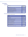
Part Numbers
Included Parts
Included Parts
Replacement
Part Number
MMX 32 VGA MTP
60-769-01
12 VDC, 1.0 A external power supply
28-071-01
3.5 mm, 5-pole captive screw connector (3)
100-457-01
3.5 mm, 2-pole captive screw connector (2)
100-454-01
3.5 mm, 3-pole captive screw connector (1)
100-456-01
Universal Switcher Control Program (on DVD)
Tweeker (small screwdriver)
MMX 32 VGA MTP User Guide
Accessories
These items can be ordered separately:
Accessories
Part Number
MTP U R A
60-869-03
MTP U R RS
60-869-04
MTP U R RSA SEQ
60-869-01
MTP RL 15HD A
60-690-01
Non-Plenum Enhanced Skew-Free A/V UTP
22-141-03
Plenum Enhanced Skew-Free A/V UTP
22-142-03
RSU 129, 19” 1U Universal Rack Shelf
60-190-01
RSB 129, 19” 1U Basic Rack Shelf
60-604-01
RSU 126, 6” deep 1U rack shelf
60-190-10
RSB 126, 6” deep basic 1U rack shelf
60-604-10
MBU 125, Under-desk mounting kit
70-077-01
MMX 32 AAP panel (black)
70-277-11
MMX 32 MAAP (black, white)
70-277-12, -22
P/S 124 multiple output 12 V power supply
60-1022-01
MMX 32 VGA MTP • Reference Information
27
Extron Warranty
Extron Electronics warrants this product against defects in materials and workmanship for a period of three years
from the date of purchase. In the event of malfunction during the warranty period attributable directly to faulty
workmanship and/or materials, Extron Electronics will, at its option, repair or replace said products or components,
to whatever extent it shall deem necessary to restore said product to proper operating condition, provided that it is
returned within the warranty period, with proof of purchase and description of malfunction to:
USA, Canada, South America,
and Central America:
Extron Electronics
1001 East Ball Road
Anaheim, CA 92805
U.S.A.
Japan:
Extron Electronics, Japan
Kyodo Building, 16 Ichibancho
Chiyoda-ku, Tokyo 102-0082
Japan
Europe and Africa:
Extron Europe
Hanzeboulevard 10
3825 PH Amersfoort
The Netherlands
China:
Extron China
686 Ronghua Road
Songjiang District
Shanghai 201611
China
Middle East:
Asia:
Extron Middle East
Extron Asia
Dubai Airport Free Zone
135 Joo Seng Road, #04-01
F12, PO Box 293666
PM Industrial Bldg.
United Arab Emirates, Dubai
Singapore 368363
Singapore
This Limited Warranty does not apply if the fault has been caused by misuse, improper handling care, electrical or
mechanical abuse, abnormal operating conditions, or if modifications were made to the product that were not
authorized by Extron.
NOTE: If a product is defective, please call Extron and ask for an Application Engineer to receive an RA (Return
Authorization) number. This will begin the repair process.
USA: 714.491.1500 or 800.633.9876
Asia:65.6383.4400
Europe:31.33.453.4040
Japan:81.3.3511.7655
Units must be returned insured, with shipping charges prepaid. If not insured, you assume the risk of loss or damage
during shipment. Returned units must include the serial number and a description of the problem, as well as the
name of the person to contact in case there are any questions.
Extron Electronics makes no further warranties either expressed or implied with respect to the product and its quality,
performance, merchantability, or fitness for any particular use. In no event will Extron Electronics be liable for direct,
indirect, or consequential damages resulting from any defect in this product even if Extron Electronics has been
advised of such damage.
Please note that laws vary from state to state and country to country, and that some provisions of this warranty may
not apply to you.
Extron Headquarters
+1.800.633.9876 (Inside USA/Canada Only)
Extron USA - West
Extron USA - East
+1.714.491.1500+1.919.850.1000
+1.714.491.1517 FAX
+1.919.850.1001 FAX
Extron Europe
+800.3987.6673
(Inside Europe Only)
+31.33.453.4040
+31.33.453.4050 FAX
Extron Asia
+800.7339.8766
(Inside Asia Only)
+65.6383.4400
+65.6383.4664 FAX
Extron Japan
+81.3.3511.7655
+81.3.3511.7656 FAX
© 2012 Extron Electronics All rights reserved.
Extron China
+4000.398766
Inside China Only
+86.21.3760.1568
+86.21.3760.1566 FAX
Extron Middle East
+971.4.2991800
+971.4.2991880 FAX
www.extron.com
Extron Korea
+82.2.3444.1571
+82.2.3444.1575 FAX
Extron India
1800.3070.3777
Inside India Only
+91.80.3055.3777
+91.80.3055.3737 FAX