1
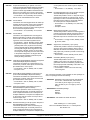
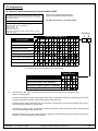
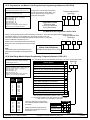
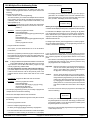
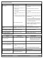
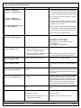
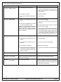
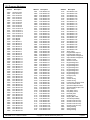
AWG) are recommended on any 1000 foot (305 m) run.
NOTE: Shared cable is not recommended for keypad, multiplex,
options bus, telephone, or siren wiring.
1.0 Specifications
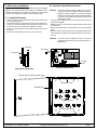
1.1 Enclosure Housing
1. The standard enclosure is manufactured from 20 Ga., cold-rolled
steel, and measures 12.5" Wide, by 14.5" High, by 3" Deep (31.8
cm Wide, by 36.8 cm High, by 7.6 cm Deep). A keyed lock is included, and this enclosure has provision for an optional tamper switch
(required for commercial burglary applications) for monitoring the
door.
1.2 Temperature
• Storage and Operating Temperature: +32° to +120°F
(0° to +49°C)
1.7 Communicator
Will report to two phone numbers with full single, double and backup reporting. Communicates in SIA (110 or 300 baud), 3/1, 3/1 Ext.,
3/1 with Parity, 3/1 Ext. with Parity, 4/1, 4/2, BFSK, Contact ID, and
Pager formats.
FCC Registration Number is ESVUSA-75333-AL-E
The ringer equivalence is 0.1B
Commercial Fire CSFM Listing Number is 7165-1062:111
Residential Fire CSFM Listing Number is 7167-1062:111
1.8 Partitions
The system has the capacity for 8 independant partitions.
1.3 Power
NOTE: The total current output capacity for all auxiliary devices,
including keypads and smoke detectors = 1.5 A standby,
2.5 A alarm. The following ratings are maximum values.
The total combined output cannot exceed the max. load
current.
• Input power:
18 VAC, 50 VA, 50 Hz./60 Hz.
• Auxiliary regulated power:
12 VDC, 1.0 A max.
• U. L. Listed Auxiliary power:
12 VDC, 1.0 A max.
• U. L. Listed Alarm Power Output: 12 VDC, 1.75 A max.
• Auxiliary power voltage range:
12 V special application
• Optional Standby battery (P334): 12 V, 7.0 AH - 35 AH max.
• Control panel current draw:
175 mA, Standby
250 mA, Alarm
1.4 Outputs
• Alarm Output:
12 VDC, 1.75 A output. Can be pro
grammed for steady or pulsed output.
• Programmable Output 1* Solid state current sink (1.0 A max.).
Shorts to ground when activated.
Connect device to Aux. power positive. Can be used for alarm, arming state, or access control.** This
output is generally programmable.
• Programmable Output 2* Solid state voltage source (500 mA
max.). Can be used for alarm, arming state, or access control.**
This output is generally programmable. For use with such compatible
devices as the Listed DS250 with a
4-wire base.
* = Current draw should be subtracted from either maximum
auxiliary or maximum alarm current draw.
** = Not investigated to the requirements of UL294.
• 8 on-board zones. Up to 128 total zones with expansion modules.
• Zone Response Time: 300 ms.
1.6 Keypads
15 Keypads
1000 feet (305 m)
6000 feet (1830 m)
in system
• Wire type:
4 conductor, unshielded, #22
AWG (0.8 mm) “Telephone
quad” or #18 AWG (1.0 mm)
quad wiring can be home-run
or daisy- chained.
NOTE: No more than 2 keypads (#22 AWG) or 3 keypads (#18
DS7400Xi Ver. 3+ Reference Guide
The DS7400Xi system allows up to 90 individual users. Each user
will have his own PIN number (the 4 digit code entered at the keypads) and his own authority level (to determine which functions he
may perform).
1.10 Lightning Protection
MOVs and spark gaps provide protection from lightning surges and
static discharges.
1.11 Burglar/Fire Zone Inputs
• Number of circuits:
• End-of-line resistor:
• Loop resistance tolerance:
8 Circuits on-board
2.2 K Ω (P/N 25944, provided)
60 ohms
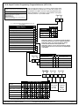
1.12 Fire Signal Initiating Circuit (2-wire mode)
Fire circuit will work with 2 or 4-wire detectors and has optional alarm
verification.
• Number of circuits:
8 Circuits on-board
• Type of circuit:
Class B, latching
• End-of-line resistor:
2.2 K Ω (P/N 25944, provided)
• Supervisory current:
5.5 mA
• Maximum short circuit current:
22 mA
• Maximum line resistance:
60 ohms
• Circuit voltage range:
8.5 to 14.1 VDC
• Total detector standby current:
2.5 mA
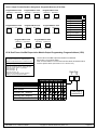
1.13 Multiplex Bus Wiring Requirements
• #22 AWG (0.8 mm). Up to 2000 feet (610 m) per system.
• #18 AWG (1.0 mm). Up to 5000 feet (1525 m) per system.
1.14 Option Bus Wiring Requirements
• Maximum wire length 1000 feet (305 m) per home-run.
1.5 Zones
• Maximum # of keypads:
• Maximum wire length each:
• Maximum wire length total:
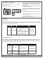
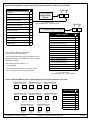
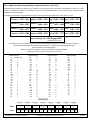
1.9 Users
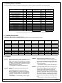
1.15 Max. Load Currents
Standby Alarm
Max. Load Currents
2.5 A
1.5 A
U. L. Installations
Non-U. L. Applications
2.5 A
2.0 A
Max. Current By Output: Not to exceed the max. load
currents listed above per column.
Aux. Power & Keypad (Combined)
Option Power
Bell Output
Programmable Output 2
Loop Power +
Copyright © 1995-96 Detection Systems, Inc.
1.0 A
1.0 A
1.0 A
500 mA
1.0 A
1.75 A
500 mA
500 mA
500 mA
X
Page 4