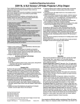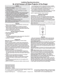
1
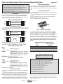
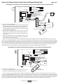
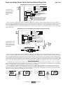
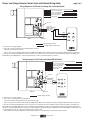
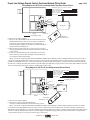
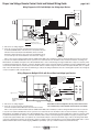
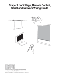
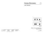
Draper Low Voltage, Remote Control,
Serial and Network Wiring Guide
Copyright © 2005 Draper Inc. Form LV-RC-Serial-Network_Wiring05-R Printed in U.S.A.
Draper Low Voltage, Remote Control, Serial and Network Wiring Guide
page 2 of 8
Notes on Cable Lengths:
Please Note
➀ Make sure power is disconnected before installing controls.
➁ LVC-III and MC1 are line voltage controls, designed to operate one
motor with activation by Low Voltage input commands.
➂ The MC1 receiver has a built in fuse that provides protection from
electrical shorts and overload.
➃ Avoid static discharge, especially to screw terminals and eye jack.
Please Note:
All input devices (low voltage LED switches, IR eye, RF receiver) which
connect to the Eye jack must be connected using electrically straight 4conductor modular cable (RJ11). This means colors do not cross over: blue
leads to blue, orange to orange, etc. (see diagram below)
Electrically Straight Data Cable
You can have a total of approximately 100 feet of cable (this includes ALL
cables connected to ALL Eye and Aux ports) per MC1 or LCV-III, up to a
maximum of 1000 feet. However, the RF Receiver can drive up to 1000 feet of
cable.
Spring-Loaded Terminals
When running wires to the spring-loaded terminals on the MC1 or LVC-III,
use the following steps:
➀ Strip outer wire sheathing back 1", then strip insulation of individual wires
back 3/8".
➁ Place screwdriver into the top slot to open the spring-loaded terminal.
➂ Slide wire into terminal connection point.
➃ Remove screwdriver. Wire is now locked into place.
Black
Green
Red
Yellow
Yellow
Red
Green
Black
Using Telephone Cable
If you use standard telephone cable, you must first remove one connector,
turn it over and re-attach, to ensure that the cable is electrically straight (see
diagram below).
Yellow
Green
Red
Black
Yellow
Green
Red
Black
Standard Telephone Cable
(Before, will not work)
“Flipped” Telephone Cable
(After-Electrically Straight-will work)
Black
Red
Green
Yellow
Yellow
Green
Red
Black
All connection wires must conform to the motor manufacturer’s
recommendation and prevailing electrical codes. The switch and control
system wires should be at least 24 AWG and no larger than 18 AWG.
Electrical Specifications—MC1
Input:
DATA:
5V AC (through "Eye" port)
Low Voltage/Serial: Dry Contact—0v AC
Output:
115V AC version: Rated at 3.8 Amps, 1/8th HP, fuse
should be 4 Amp 250V 5x20mm fast or slow blow.
230V AC version: Rated at 1.9 Amps, 1/8th HP, fuse
should be 2 Amp 250V 5x20mm fast or slow blow.
Dimensions: 21/8" W x 31/4" L x 7/8" H.
Electrical Specifications—LVC-III
Input:
DATA:
5V AC (through "Eye" port)
Low Voltage/Serial: Dry Contact—0v AC
Output:
115V AC version: Rated at 6 Amps, 1/3 HP, fuse
should be 6.3 Amp 250V 5x20mm fast or slow blow.
230V AC version: Rated at 3 Amps, 1/3 HP, fuse
should be 3.15 Amp 250V 5x20mm fast or slow blow.
Note: Holds contact 180 seconds.
Electrical Connections
Screens, AeroLifts and Micro Projector Lifts operate on 110-120V, 60 Hz.
AC current.
Screens, AeroLifts and Micro Projector Lifts are shipped with internal
wiring complete and control switch(es) fully boxed. Wire to connect screen to
switch(es) and switch(es) to power supply should be furnished by installer.
Connections should be made in accordance with approved wiring
diagrams, and wiring should comply with national and local electrical codes.
All operating switches should be “off” before power is connected.
www.draperinc.com
Notes on Power Consumption:
Any input device may be connected to any available Eye port. All Eye
ports are "powered" by the MC1 or LVC-III they feed off of. Each MC1 Eye
port provides 2 milliAmps to the connected input devices; the LVC-III Eye port
provides 75 milliAmps at 5V of power. You may attach any combination of
input devices to an MC1 or LVC-III Eye port, as long as the combined power
requirements do not exceed the available power from the MC1 or LVC-III (see
chart). RF receivers and LED switches require their own power supply
when used with the MC1. Power supply can power up to three input
devices.
Input Device Power Consumption Chart
Input
Device
Power Consumption
(milliAmps)
RF Remote Receiver
IR Receiver Eye
LED Wall Switch
Dry Contact Switch
* Requires additional, separate power supply.
33*
2
24*
0
Please Note:
Wiring diagrams are available for each control
and input device at www.draperinc.com.
Table of Contents
2-way serial communication (MC1) with low voltage dry contact wall switch ..................3
2-way serial communication (MC1) with low voltage LED wall switch .............................3
2-way serial communication (MC1) with low voltage RF Remote Control .......................4
2-way serial communication (MC1) with low voltage IR Remote Control ........................4
2-way serial communication (MC1) with RS232 ..............................................................5
Network communication via Ethernet with MC1 and IPD4 ..............................................5
LVC-III with low voltage dry contact wall switch ...............................................................6
LVC-III with low voltage LED wall switch .........................................................................6
LVC-III with low voltage RF Remote Control ...................................................................7
LVC-III with low voltage IR Remote Control .....................................................................7
LVC-III with multiple input devices ...................................................................................8
Multiple LVC-IIIs with one or more input devices .............................................................8
If you encounter any difficulties installing/wiring your MC1 or LVC-III, call your
dealer or Draper, Inc., Spiceland, Ind., (765) 987-7999; fax (765) 987-7142; or
e-mail [email protected].
(765) 987-7999
Draper Low Voltage, Remote Control, Serial and Network Wiring Guide
page 3 of 8
Wiring Diagram for Two-Way Serial Communication with RS232 and Low Voltage Dry Contact Wall Switch
White-Common
Red-to Screen (directional)
Brown-to Screen (directional)
Black-Hot to 110-120V AC
Green/Yellow-Ground
Program LED
Wall Switch
Low Voltage Wiring by others
AC Wiring by electrician
Fuse
RS232 Data FROM Control System
RS232 Data TO Control System
Signal Ground & Manual Switch Common
Manual Switch Down
Manual Switch Up
White
Black
Red
Eye Port for IR Eye. For RF Receiver or LED
Wall Switch, a Splitter and a Power Supply
is required. Plug RF Receiver or LED Wall
Switch and Power Supply into splitter, then
run cable from Splitter to MC1 Eye Port.
MC1
➀ Wire Screen according to diagram.
➁ Press “Up.” If screen goes down, switch black and red wires at the switch.
Motor directions will now be reversed.
Wire to connect power to MC1 should be between 18 AWG and 12 AWG (solid or stranded) 2 conductors with ground. Wire size needs to be sufficient to carry
the motor load. Red and Black wires are the “open” and “close” leads from the motor. The MC1 comes enclosed in a metal box conforming to the National
Electric Code (NEC) with appropriate spacing between the wires and any exposed parts of the box. Wire to connect the switch to the dry contacts on the MC1
must be 3-conductor.
Wiring Diagram for Two-Way Serial Communication with RS232 and Low Voltage LED Wall Switch
White-Common
Red-to Screen (directional)
Brown-to Screen (directional)
Black-Hot to 110-120V AC
Green/Yellow-Ground
Program LED
Low Voltage Wiring by others
AC Wiring by electrician
Fuse
Power
Supply
MC1
Eye
Electrically
Straight
Data Cable
Main
Aux
RS232 Data FROM Control System
RS232 Data TO Control System
Signal Ground & Manual Switch Common
Manual Switch Down
Manual Switch Up
Eye
Eye Port
➀ Wire Screen according to diagram.
➁ Press “Up.” If screen goes down, Press and hold “Stop” for five seconds,
then press the “Up” button. Motor directions will now be reversed.
Electrically Straight
Data Cable
Splitter
LED Wall Switch
Wire to connect power to MC1 should be between 18 AWG and 12 AWG (solid or stranded) 2 conductors with ground. Wire size needs to be sufficient to
carry the motor load. Red and Black wires are the “open” and “close” leads from the motor. The MC1 comes enclosed in a metal box conforming to the National
Electric Code (NEC) with appropriate spacing between the wires and any exposed parts of the box. LED switch connects to MC1 using modular data or telephone cord (RJ11), which must be isolated from the AC power line. This wire is commonly called Silver Satin. It must be electrically straight (see explanation on
page 2). LED switch must be within 1,000 feet of the MC1, must have a power supply, and must run through a splitter before the MC1. Power supply can power
up to three input devices. A dry contact wall switch may also be connected to the MC1 using 3-conductor wire.
When a button is pressed, the LED next to the button turns from green to red, and remains red until another button is pressed.
www.draperinc.com
(765) 987-7999
Draper Low Voltage, Remote Control, Serial and Network Wiring Guide
page 4 of 8
Wiring Diagram for Two-Way Serial Communication with RS232 and low voltage Radio Frequency Remote Control
Program LED
White-Common
Red-to Screen (directional)
Brown-to Screen (directional)
Black-Hot to 110-120V AC
Green/Yellow-Ground
Low Voltage Wiring by others
AC Wiring by electrician
Fuse
Power
Supply
Aux
RS232 Data FROM Control System
RS232 Data TO Control System
Signal Ground & Manual Switch Common
Manual Switch Down
Manual Switch Up
MC1
Eye
Main
Electrically Straight
Data Cable
Electrically Straight
Data Cable
Eye
➀ Wire Screen according to diagram.
➁ Before you can send commands, the RF receiver must “learn” the remote
transmitter. When the RF receiver first receives power, a red LED on the
bottom of the receiver activates. This means it is in learning mode. To
“learn” the transmitter, simply point it at the RF receiver and hold down the
“up” button until the red LED goes out.
➂ Once the remote is learned, press “Up” to test the screen. If screen goes
down, then the motor direction needs to be reversed. Press and hold
“Stop” for five seconds, then press the “Up” button. Motor directions will
now be reversed.
➃ To learn a second transmitter (up to five total allowed), press the “learn”
button on the bottom of the receiver, and repeat step 2 (you will have 10
seconds after pressing the “learn” button).
RF Receiver
Splitter
RF Transmitter
Transmitter range: 100 feet
WR
T/R
OP
ST
Wire to connect power to MC1 should be between 18 AWG and 12 AWG (solid or stranded) 2 conductors with ground. Wire size needs to be sufficient to
carry the motor load. Red and Black wires are the “open” and “close” leads from the motor. The MC1 comes enclosed in a metal box conforming to the National
Electric Code (NEC) with appropriate spacing between the wires and any exposed parts of the box. RF receiver is connected to MC1 using low voltage modular
data or telephone cord (RJ11), which is isolated from the AC power line. This wire is commonly called Silver Satin. It must be electrically straight (see explanation on page 2). The RF Receiver must be within 1,000 feet of the MC1, must have a power supply, and must run through a splitter before the MC1. Power
supply can power up to three input devices. A dry contact wall switch may also be connected to the MC1 using 3-conductor wire.
Wiring Diagram for Two-Way Serial Communiation with RS232 and low voltage Infrared Remote Control
White-Common
Red-to Screen (directional)
Brown-to Screen (directional)
Black-Hot to 110-120V AC
Green/Yellow-Ground
Program LED
Low Voltage Wiring by others
AC Wiring by electrician
Fuse
RS232 Data FROM Control System
RS232 Data TO Control System
Signal Ground & Manual Switch Common
Manual Switch Down
Manual Switch Up
MC1
Electrically Straight
Data Cable
IR Eye
Eye Port
➀ Wire Screen according to diagram.
➁ Press “Up.” If screen goes down, Press and hold “Stop” for five seconds,
then press the “Up” button. Motor directions will now be reversed.
IR Transmitter
Transmitter range: 70 feet
Wire to connect power to MC1 should be between 18 AWG and 12 AWG (solid or stranded) 2 conductors with ground. Wire size needs to be sufficient to
carry the motor load. Red and Black wires are the “open” and “close” leads from the motor. The MC1 comes enclosed in a metal box conforming to the National
Electric Code (NEC) with appropriate spacing between the wires and any exposed parts of the box. IR Eye is connected to MC1 using low voltage modular data
or telephone cord (RJ11), which is isolated from the AC power line. This wire is commonly called Silver Satin. It must be electrically straight (see explanation on
page 2). The IR eye must be within 100 feet of the MC1. A dry contact wall switch may also be connected to the MC1 using 3-conductor wire.
www.draperinc.com
(765) 987-7999
Draper Low Voltage, Remote Control, Serial and Network Wiring Guide
page 5 of 8
Wiring Diagram for Two-Way Serial Communication with RS232
White-Common
Red-to Screen (directional)
Brown-to Screen (directional)
Black-Hot to 110-120V AC
Green/Yellow-Ground
Program LED
See separate Serial
Communication-RS232
Instruction sheet for
enabling RS232 with
the MC1.
Low Voltage Wiring by others
AC Wiring by electrician
Fuse
RS232 Data FROM Control System
RS232 Data TO Control System
Signal Ground & Manual Switch Common
Manual Switch Down
Manual Switch Up
Eye Port for IR Eye. For RF Receiver or LED
Wall Switch, a Splitter and a Power Supply
is required. Plug RF Receiver or LED Wall
Switch and Power Supply into splitter, then
run cable from Splitter to MC1 Eye Port.
MC1
Wire to connect power to MC1 should be between 18 AWG and 12 AWG (solid or stranded) 2 conductors with ground. Wire size needs to be sufficient to
carry the motor load. Red and Black wires are the “open” and “close” leads from the motor. The MC1 comes enclosed in a metal box conforming to the National
Electric Code (NEC) with appropriate spacing between the wires and any exposed parts of the box. Wire to connect system integration products or other
controls using RS232 (two-way serial communication) to MC1 must be 3 conductors with ground. A dry contact wall switch may also be connected to the MC1
using 3-conductor wire.
Wiring Diagram for One-Way Network Communication via Ethernet with IPD4
White-Common
Red-to Screen (directional)
Brown-to Screen (directional)
Black-Hot to 110-120V AC
Green/Yellow-Ground
Program LED
Low Voltage Wiring by others
AC Wiring by electrician
Fuse
RS232 Data FROM Control System
RS232 Data TO Control System
Signal Ground & Manual Switch Common
To
Manual Switch Down
RF
Sys Sys
Sys
Manual Switch Up
1
2
3
Trans.
MC1
For additional motors, plug
additional MC1s into “Sys
2” and “Sys 3” jacks. Jack
is also provided in IPD4 for
RF Transmitter.
Electrically Straight
Data Cable
Power
Supply
IPD 4
To Ethernet
For connecting to LAN
USB Adapter
Needed only if plugging
into USB port
Serial Port Adapter
Electrically Straight
Data Cable
Wire to connect power to MC1 should be between 18 AWG and 12 AWG (solid or stranded) 2 conductors with ground. Wire size needs to be sufficient to
carry the motor load. Red and Black wires are the “open” and “close” leads from the motor. The MC1 comes enclosed in a metal box conforming to the National
Electric Code (NEC) with appropriate spacing between the wires and any exposed parts of the box. IPD 4 for control via Ethernet (network communication) is
connected to MC1 using low voltage modular data or telephone cord (RJ11), which is isolated from the AC power line. This wire is commonly called Silver Satin.
It must be electrically straight (see explanation on page 2). IPD4 must be within 1,000 feet of MC1. A dry contact wall switch may also be connected to the MC1
using 3-conductor wire. An RF transmitter can also be connected to the IPD4 to allow commands to be transmitted to a radio receiver connected to the MC1.
Protocol and Address
The IPD4 shall be pre-configured with an IP address of 192.168.42.4 and port 4001. To communicate with the IPD4, establish a connection to its address
and port, and then transmit data packets containing instructions. The protocol for the IPD4 are not as complete as that for the RS232 protocol used by the MC1,
but they are compatible. Please consult the RS232 Protocol Guide for details of the instructions.
Follow the standard pin configuration for MC1 wiring (black always on the left, straight through). The ENET port on the IPD4 allows for the network connection to be established. The RJ45 connection (T568A) can be configured as a standard straight through connection (see Fig. 1 below) when connected to
network hub. A cross-over connection (T568B, see Fig. 2 below) is used when connecting directly to a PC without a network connection. A data quality CAT5
cable must be used for the ENET port on the IPD4 and connect to the network.
Wire Color
Orange/White
Orange
Green/White
Blue
Blue/White
Green
Brown/White
Brown
Pins 4, 5, 7 & 8
are not used
Pins 4, 5, 7 & 8
are not used
Receive (3 & 6)
Transmit (1 & 2)
12345678
12345678
Pin #
Pin 1
Pin 2
Pin 3
Pin 4
Pin 5
Pin 6
Pin 7
Pin 8
Transmit (1 & 2)
Receive (3 & 6)
12345678
Transmit (3 & 6)
Receive (1 & 2)
12345678
Pins 4, 5, 7 & 8
are not used
Pin #
Pin 1
Pin 2
Pin 3
Pin 4
Pin 5
Pin 6
Pin 7
Pin 8
Straight-Through
Wire
Becomes
1
1
2
2
3
3
6
6
Figure 1
Wire Color
Orange/White
Orange
Green/White
Blue
Blue/White
Green
Brown/White
Brown
Figure 2
www.draperinc.com
(765) 987-7999
Crossed-Over
Wire
Becomes
1
3
2
6
3
1
6
2
Receive (3 & 6)
Transmit (1 & 2)
Pins 4, 5, 7 & 8
are not used
Draper Low Voltage, Remote Control, Serial and Network Wiring Guide
page 6 of 8
Wiring Diagram for LVC-III with Low Voltage Dry Contact Wall Switch
White-Neutral (Common) to screen & 110-120V AC
Red-to screen (directional)
Brown-to screen (directional)
Yellow-to 110-120V AC
Black-to 110-120V AC
Green-Ground
Eye Port
Dry Contacts
3 Button Wall Switch
DOWN - Black
COM - White
UP - Red
Black
White
Red
Aux Port
LVC-III
Dashed wiring by electrician
➀ Wire Screen according to diagram.
➁ Press “Up.” If screen goes down, switch red and black wires at switch.
Motor directions will now be reversed.
Low voltage wiring to switch by others
Wall Switch
Wire to connect power to LVC-III should be between 18 AWG and 12 AWG (solid or stranded) 2 conductors with ground. Wire size needs to be sufficient
to carry the motor load. Red and Black wires are the “open” and “close” leads from the motor. The LVC-III comes enclosed in a metal box conforming to the
National Electric Code (NEC). Wire to connect the switch to the dry contacts on the LVC-III must be 3-conductor.
Wiring Diagram for LVC-III with Low Voltage LED Wall Switch
White-Neutral (Common) to screen & 110-120V AC
Red-to screen (directional)
Brown-to screen (directional)
Yellow-to 110-120V AC
Black-to 110-120V AC
Green-Ground
Eye Port
Electrically Straight
Data Cable
Aux Port
LVC-III
Dashed wiring by electrician
➀ Wire Screen according to diagram.
➁ Press “Up.” If screen goes down, up and down wires
from motor should be switched. Motor directions will now be reversed.
LED Wall Switch
Wire to connect power to LVC-III should be between 18 AWG and 12 AWG (solid or stranded) 2 conductors with ground. Wire size needs to be sufficient
to carry the motor load. Red and Black wires are the “open” and “close” leads from the motor. The LVC-III comes enclosed in a metal box conforming to the
National Electric Code (NEC). LED switch connects to LVC-III using modular data or telephone cord (RJ11), which must be isolated from the AC power line.
This wire is commonly called Silver Satin. It must be electrically straight (see explanation on page 2). LED switch must be within 1,000 feet of the LVC-III. A dry
contact wall switch may also be connected to the LVC-III using 3-conductor wire.
When a button is pressed, the LED next to the button turns from green to red, and remains red until another button is pressed.
www.draperinc.com
(765) 987-7999
Draper Low Voltage, Remote Control, Serial and Network Wiring Guide
page 7 of 8
Wiring Diagram for LVC-III with Low Voltage Radio Frequency Remote Control
White-Neutral (Common) to screen & 110-120V AC
Red-to screen (directional)
Brown-to screen (directional)
Yellow-to 110-120V AC
Black-to 110-120V AC
Green-Ground
Eye Port
Electrically Straight
Data Cable
RF Receiver
Aux Port
WR
LVC-III
T/R
OP
ST
Dashed wiring by electrician
➀ Wire Screen according to diagram.
➁ Before you can send commands, the RF receiver must “learn” the remote
transmitter. When the RF receiver first receives power, a red LED on the
bottom of the receiver activates. This means it is in learning mode. To
“learn” the transmitter, simply point it at the RF receiver and hold down the
“up” button until the red LED goes out.
➂ Once the remote is learned, press “Up” to test the screen. If screen goes
down, up and down wires from motor should be switched. Motor directions will
now be reversed.
➃ To learn a second transmitter (up to five total allowed), press the “learn”
button on the bottom of the receiver, and repeat step 2 (you will have 10
seconds after pressing the “learn” button).
RF Transmitter
Transmitter range: 100 feet
Wire to connect power to LVC-III should be between 18 AWG and 12 AWG (solid or stranded) 2 conductors with ground. Wire size needs to be sufficient to
carry the motor load. Red and Black wires are the “open” and “close” leads from the motor. The LVC-III comes enclosed in a metal box conforming to the National Electric Code (NEC). RF receiver is connected to LVC-III using low voltage modular data or telephone cord (RJ11), which is isolated from the AC power
line. This wire is commonly called Silver Satin. It must be electrically straight (see explanation on page 2). The RF receiver must be within 1,000 feet of the LVCIII. A dry contact wall switch may also be connected to the MC1 using 3-conductor wire.
Wiring Diagram for LVC-III with Low Voltage Infrared Remote Control
White-Common to screen & 110-120V AC
Red-to screen (directional)
Brown-to screen (directional)
Yellow-to 110-120V AC
Black-to 110-120V AC
Green-Ground
Dashed wiring by electrician
Eye Port
IR Eye
Electrically Straight
Data Cable
Aux Port
LVC-III
IR Transmitter
Transmitter range: 70 feet
➀ Wire Screen according to diagram.
➁ Press “Up.” If screen goes down, up and down wires
from motor should be switched. Motor directions will now be reversed.
Wire to connect power to LVC-III should be between 18 AWG and 12 AWG (solid or stranded) 2 conductors with ground. Wire size needs to be sufficient
to carry the motor load. Red and Black wires are the “open” and “close” leads from the motor. The LVC-III comes enclosed in a metal box conforming to the
National Electric Code (NEC). IR Eye is connected to LVC-III using low voltage modular data or telephone cord (RJ11), which is isolated from the AC power line.
This wire is commonly called Silver Satin. It must be electrically straight (see explanation on page 2). The IR eye must be within 100 feet of the LVC-III. A dry
contact wall switch may also be connected to the LVC-III using 3-conductor wire.
www.draperinc.com
(765) 987-7999
Draper Low Voltage, Remote Control, Serial and Network Wiring Guide
page 8 of 8
Wiring Diagram for LVC-III with Multiple Low Voltage Input Devices
Black
White
Red
White-Common to screen & 110-120V AC
Red-to screen (directional)
Brown-to screen (directional)
Yellow-to 110-120V AC
Black-to 110-120V AC
Green-Ground
Wall Switch
Eye Port
Aux
Splitter
Aux Port
RT
/R
RF Receiver
transmitter range 100 feet
OP
ST
Eye
LVC-III
Electrically Straight
Data Cable
(Eye to Main)
RF Transmitter
W
Electrically Straight
Data Cable
Eye
Main
Dry Contacts
3 Button Wall Switch
DOWN - Black
COM - White
UP - Red
Dashed wiring by electrician
Low voltage wiring to switch by others
Electrically Straight
Data Cable
➀ Wire Screen according to diagram.
➁ Press “Up.” If screen goes down, up and down wires from motor should
be switched (LED Wall Switch or IR or RF remote control). Motor directions
will now be reversed. (For Dry Contact Wall Switch, switch out red and
black wires.) Please Note: RF receiver must “learn” the transmitter. Receivers can “learn” up to five remote transmitters. See instructions on page 7.
LED Wall Switch
Wire to connect power to LVC-III should be between 18 AWG and 12 AWG (solid or stranded) 2 conductors with ground. Wire size needs to be sufficient
to carry the motor load. Red and Black wires are the “open” and “close” leads from the motor. The LVC-III comes enclosed in a metal box conforming to the
National Electric Code (NEC). If using RF receiver, IR Eye LED wall switch, connect to LVC-III using low voltage modular data or telephone cord (RJ11), which
is isolated from the AC power line. This wire is commonly called Silver Satin. It must be electrically straight (see explanation on page 2). LED Wall Switch or RF
receiver must be within 1,000 feet of LVC-III; IR eye must be within 100 feet of LVC-III. If using more than one device that requires modular cable, use a splitter.
A dry contact wall switch may be connected to the LVC-III using 3 conductor wire with ground. RS232 connection to AV Integration systems is also through dry
contacts. Use splitters to add control input devices.
Wiring Diagram for Multiple LVC-IIIs with One or More Low Voltage Input Devices
White-Neutral (Common) to screen & 110-120V AC
Red-to screen (directional)
Brown-to screen (directional)
Yellow-to 110-120V AC
Black-to 110-120V AC
Green-Ground
Eye Port
Dry Contacts
3 Button Wall Switch
DOWN - Black
COM - White
UP - Red
Electrically Straight
Data Cable
A maximum of six (6) LVC-III
modules can be linked
together.
Black
White
Red
Dashed wiring by electrician
Low voltage wiring by others
LVC-III
Aux Port
Wall Switch
➀ Wire Screen according to diagram.
Please Note: In above configuration, the dry contact switch controls
➁ Press “Up.” If screen goes down, up and down wires
only one LVC-III; dry contact switches must be wired to each LVC-III.
from motor should be switched. Motor directions will now be reversed.
Wire to connect power to LVC-III should be between 18 AWG and 12 AWG (solid or stranded) 2 conductors with ground. Wire size needs to be sufficient
to carry the motor load. Red and Black wires are the “open” and “close” leads from the motor. The LVC-III comes enclosed in a metal box conforming to the
National Electric Code (NEC). If using RF receiver, IR Eye LED wall switch, connect to LVC-III using low voltage modular data or telephone cord (RJ11), which
is isolated from the AC power line. This wire is commonly called Silver Satin. It must be electrically straight (see explanation on page 2). If using more than
one device that requires modular cable, use a splitter. A dry contact wall switch may be connected to the LVC-III using 3 conductor wire with ground. RS232
connection to AV Integration systems is also through dry contacts. Use splitters to add control input devices. Use electrically straight modular cable to connect
additional LVC-III modules. Connect LVC-IIIs by going FROM “Aux” port TO “Eye” port. Up to six LVC-III modules may be linked in this way.
www.draperinc.com
(765) 987-7999