1
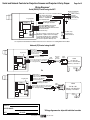
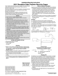
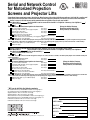
Serial and Network Control
for Motorized Projection
Screens and Projector Lifts
by
Please Note: Draper motorized screens, AeroLifts, the Micro Projector Lift and the LCD Lift come with one 110V-120V AC 3-position wall
switch (for ScissorLift, Revelation, Phantom and Orbiter, see their respective submittals). For Serial or IP control, select from below:
Control a screen or lift with two-way serial communication using RS232. For this you need an MC1.
How Many MC1s?
(Up to four MC1s can be connected via the MC1 1-to-4 Splitter. How many 1-to-4 Splitters?
Factory install MC1 inside screen case? 1
Yes
No
)
(Except for Orbiter, Phantom,
There are several additonal control options to choose from:
Revelation and ScissorLift. For
Dry contact 3-button wall switch
How many?
these products, see submittals.)
Low Voltage LED wall switch, power supply and splitter*
How many?
3-position key control switch
How many?
Power supply (on-off) key switch?
How many?
IR remote control eye and one transmitter*
Add IR remote control transmitter
How many extra transmitters?
RF remote control receiver, one transmitter, power supply and splitter*
Add RF remote control transmitter
How many extra transmitters?
*Please note: The MC1 has one data cable input jack. If using more than one IR eye, LED wall switch or RF receiver, a splitter is required. If using more than
one LED wall switch or RF receiver, an additional power supply may also be required (power supply powers up to three total receivers or LED switches).
Add data cable splitter (1 per 2 additional inputs)
How many?
Add power supply
How many?
Control a screen or lift with Network Communication (Ethernet). For this you need an MC1 and an LS100.
How Many MC1s?
(Up to four MC1s can be connected via the MC1 1-to-4 Splitter. How many 1-to-4 Splitters?
How Many LS100s (Each LS100 can handle one MC1)? *
)
Factory install MC1 inside screen case? 2
Yes
No
*Please note: The LS100 connects to the MC1 through the serial pins. To connect an LS100 to an MC1, one RS232 (serial) adapter and one MJA4 modular jack
adapter are required.
Add MJA4 Modular Cable Adapter
How many?
Add RS232 (Serial) Adapter
How many?
There are several additonal control options to choose from:
(Except for Orbiter, Phantom,
Dry contact 3-button wall switch
How many?
Revelation and ScissorLift. For
Low Voltage LED wall switch, power supply and splitter*
How many?
these products, see submittals.)
3-position key control switch
How many?
Power supply (on-off) key switch
How many?
IR remote control eye and one transmitter*
Add IR remote control transmitter
How many extra transmitters?
RF remote control receiver and one transmitter*
Add RF remote control transmitter
How many extra transmitters?
*Please note: The MC1 has one data cable input jack. If using an RF receiver, IR eye or LED wall switch, a splitter is required. If using more than one LED wall
switch or RF receiver, an additional power supply may also be required (power supply powers up to three total receivers or LED switches).
Add data cable splitter (1 per 2 additional inputs)
How many?
Add power supply
How many?
1
MC1 can be built into the following products:
Access/Series E: Factory installed MC1 increases case length by 21/2"
Access/Series V: Factory installed MC1 increases case length by 1"
Signature/Series E: Does not increase case length
Signature/Series V: Does not increase case length
Silhouette/Series E: Factory installed MC1 increases case length by 73/8"
Silhouette/Series V: Factory installed MC1 increases case length by 73/8"
Ultimate Access/Series E: Does not increase case length
Ultimate Access/Series V: Does not increase case length
PROJECT:
SCREEN MODEL:
ARCHITECT:
CONTRACTOR:
SUPPLIER:
Copyright © 2007 Draper Inc. Form Serial-NetworkControl_PlanSheet07-R
Printed in U.S.A.
DATE:
REVISED:
Serial and Network Controls for Projection Screens and Projector Lifts by Draper
Wiring Diagrams*
Page 2 of 2
Serial (RS232) Control using the MC1
Internal Screen Wiring
Program LED
White-Common to screen & 110-120V AC Neutral
Red-to Screen (directional)
Brown-to Screen (directional)
Black-Hot to 110-120V AC
Green/Yellow-Ground
White (Common)
Red (Up)
Black (Down)
Green (Ground)
Low Voltage Wiring by others
AC Wiring by electrician
Fuse
RS232 Data FROM Control System
RS232 Data TO Control System
Signal Ground & Manual Switch Common
Manual Switch Down
Manual Switch Up
MC1
Eye Port for IR Eye. For RF Receiver or LED
Wall Switch, a Splitter and a Power Supply
is required. Plug RF Receiver or LED Wall
Switch and Power Supply into splitter, then
run cable from Splitter to MC1 Eye Port.
Location of key
operated on-off
switch if furnished
To 110-120V Line
See separate Serial Communication-RS232 Instruction sheet for instructions on enabling RS232 with the MC1.
Network (IP) Control using the MC1
Program LED
White-Common
Red-to Screen (directional)
Brown-to Screen (directional)
Black-Hot to 110-120V AC
Green/Yellow-Ground
Low Voltage Wiring by others
AC Wiring by electrician
Fuse
Yellow = Rx (Receive data from control system)
Green = Tx (Transmit data to control system)
Black = Gnd (Signal Ground)
MJA4
Adapter
Electrically
Straight
Data Cable
RS232
Adapter
LS100
192.168.1.101
Subnet = 255.255.255.0
Gateway = 192.168.1.1
Red = Unused
To Ethernet
MC1
Or
Program LED
Fuse
Power
Supply
White-Common
Red-to Screen (directional)
Brown-to Screen (directional)
Black-Hot to 110-120V AC
Green/Yellow-Ground
Low Voltage Wiring by others
AC Wiring by electrician
Yellow = Rx (Receive data from control system)
Green = Tx (Transmit data to control system)
Black = Gnd (Signal Ground)
Red = Unused
LS100
RS232
Adapter
192.168.1.101
Subnet = 255.255.255.0
Gateway = 192.168.1.1
To Ethernet
MC1
Data
Cable
Power
Supply
PROJECT:
SCREEN MODEL:
DATE:
* Wiring diagrams also ship with individual controls
REVISED:
www.draperinc.com
(765) 987-7999