1
(8527+(50
'5,9(6
3URILEXV0'3
&RPPXQLFDWLRQV
,QWHUIDFH
7HFKQLFDO#0DQXDO
+$7968948334##,VVXH#4
&RPSDWLEOH#ZLWK#9HUVLRQ#51[#6RIWZDUH
#&RS\ULJKW#(XURWKHUP#'ULYHV#/LPLWHG#5333
All rights strictly reserved. No part of this document may be stored in a retrieval system, or transmitted in any form or
by any means to persons not employed by a Eurotherm group company without written permission from Eurotherm
Drives Ltd.
Although every effort has been taken to ensure the accuracy of this document it may be necessary, without notice, to
make amendments or correct omissions. Eurotherm Drives cannot accept responsibility for damage, injury, or expenses
resulting therefrom.
6DIHW\#,QIRUPDWLRQ
Please read this information BEFORE installing the equipment.
$
,QWHQGHG#8VHUV
This manual is to be made available to all persons who are required to install, configure or
service equipment described herein, or any other associated operation.
The information given is intended to highlight safety issues, and to enable the user to obtain
maximum benefit from the equipment.
$SSOLFDWLRQ#$UHD
The equipment described is intended for industrial motor speed control.
3HUVRQQHO
Installation, operation and maintenance of the equipment should be carried out by qualified
personnel. A qualified person is someone who is technically competent and familiar with all
safety information and established safety practices; with the installation process, operation and
maintenance of this equipment; and with all the hazards involved.
5()(5#72#<285#0$,1#352'8&7#0$18$/#)25#63(&,),$)(7<
,1)250$7,21#$%287#7+(#'(9,&(#<28#$5(#&21752//,1*
&RQW16
&RQW17
&RQWHQWV
&RQWHQWV##############################################################################################################3DJH
352),%860'3#&20081,&$7,216#,17(5)$&(
4
$#6\VWHP#2YHUYLHZ1111111111111111111111111111111111111111111111111111111111111111111111111111111111111111111 4
7KH#352),%86#3URWRFRO1111111111111111111111111111111111111111111111111111111111111111111111111111111111111111111111111 4
3ULQFLSOHV#RI#2SHUDWLRQ 1111111111111111111111111111111111111111111111111111111111111111111111111111111111111111111111111 5
• ,22#'DWD#([FKDQJH 111111111111111111111111111111111111111111111111111111111111111111111111111111111111 5
3URGXFW#)HDWXUHV11111111111111111111111111111111111111111111111111111111111111111111111111111111111111111111111111111111111 6
3URGXFW#&RGH#DQG#&RQWHQWV 111111111111111111111111111111111111111111111111111111111111111111111111111111111111111111 6
,QVWDOODWLRQ 1111111111111111111111111111111111111111111111111111111111111111111111111111111111111111111111111111111 7
:LULQJ#WKH#6\VWHP111111111111111111111111111111111111111111111111111111111111111111111111111111111111111111111111111111111 7
• &DEOH#6SHFLILFDWLRQ 111111111111111111111111111111111111111111111111111111111111111111111111111111111111 7
• (DUWKLQJ#WKH#6KLHOG1111111111111111111111111111111111111111111111111111111111111111111111111111111111111 8
• 8VHU#&RQQHFWLRQV#WR#WKH#0DLQ#6HULDO#3RUW#+34, 111111111111111111111111111111111111111111111 8
• 7HUPLQDWRUV 11111111111111111111111111111111111111111111111111111111111111111111111111111111111111111111111 8
• 7HUPLQDO#%ORFN#+7%4,#&RQQHFWLRQV 11111111111111111111111111111111111111111111111111111111111111 9
• 5HSHDWHUV 11111111111111111111111111111111111111111111111111111111111111111111111111111111111111111111111111 9
)LWWLQJ#DQG#&RQQHFWLQJ#WR#WKH#7HFKQRORJ\#%R[1111111111111111111111111111111111111111111111111111111111111111 9
&RQQHFWLQJ#WR#WKH#7HFKQRORJ\#&DUG#+8;769#RQO\, 1111111111111111111111111111111111111111111111111111111111 :
• 8;769#7\SHV#7/#8#)#9 11111111111111111111111111111111111111111111111111111111111111111111111111111111 :
• 8;769#7\SHV#:/#;/#<#)#43 11111111111111111111111111111111111111111111111111111111111111111111111111 :
:LULQJ#'LDJUDP 11111111111111111111111111111111111111111111111111111111111111111111111111111111111111111111111111111111111 ;
,QLWLDO#&KHFN#IRU#&RQQHFWLRQ111111111111111111111111111111111111111111111111111111111111111111111111111111111111111111 ;
8QGHUVWDQGLQJ#WKH#/('#,QGLFDWLRQV 11111111111111111111111111111111111111111111111111111111111111111111111111111111 <
• 1HWZRUN#DQG#0RGXOH#/('#,QGLFDWLRQV 111111111111111111111111111111111111111111111111111111111 <
,QLWLDO#6HW0XS#IRU#3URILEXV1111111111111111111111111111111111111111111111111111111111111111111111111111111 43
&RQILJXULQJ#WKH#'ULYH 1111111111111111111111111111111111111111111111111111111111111111111111111111111111111111111111111 43
&RQILJXULQJ#WKH#3/&26&$'$#6XSHUYLVRU 1111111111111111111111111111111111111111111111111111111111111111111111 45
*6'#)LOHV 1111111111111111111111111111111111111111111111111111111111111111111111111111111111111111111111111111111111111111111 48
&RQILJXUDWLRQ#'DWD#+&IJB'DWD, 11111111111111111111111111111111111111111111111111111111111111111111111111111111111 48
• 'HPDQG#'DWD#3URWRFRO 1111111111111111111111111111111111111111111111111111111111111111111111111111 4;
'DWD#(QFRGLQJ 11111111111111111111111111111111111111111111111111111111111111111111111111111111111111111111111111111111111 4<
352),%86#'LDJQRVWLFV 111111111111111111111111111111111111111111111111111111111111111111111111111111111111 53
7URXEOHVKRRWLQJ 111111111111111111111111111111111111111111111111111111111111111111111111111111111111111111111 54
,QWHUQDO#'LDJQRVWLFV 1111111111111111111111111111111111111111111111111111111111111111111111111111111111111111111111111111 55
• ,17#',$*#6(/(&7#3DUDPHWHU#9DOXHV111111111111111111111111111111111111111111111111111111111 55
'HFLPDO2+H[DGHFLPDO#7DEOH 111111111111111111111111111111111111111111111111111111111111111111111111111111111111111 56
&RQW18
&RQWHQWV
&RQWHQWV##############################################################################################################3DJH
&RQW19
4
352),%860'3#&20081,&$7,216#,17(5)$&(
$#6\VWHP#2YHUYLHZ
Area
Computer
Factory
Level
MMS, TCP/IP Backbone
CNC
Cell
Level
PC/VME
Host
PROFIBUS-FMS
PLC
PC
Field
Level
DCS
PROFIBUS-DP
Motor
Drives
I/O
Temp
Controller
PROFIBUS-PA
Field
Device
Transmitter
Field
Device
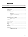
Figure 1 PROFIBUS Application Areas
The PROFIBUS Option supports the PROFIBUS-DP variant of the PROFIBUS protocol which
is designed especially for communication between automatic control systems and distributed I/O
at the device level. It is most often used to allow a central Programmable Logic Controller or PC
based control system to use external ‘slave’ devices for I/O or specialised functions. The
principal advantage is that these devices may be distributed around a machine, thereby saving on
the cost of point to point wiring. The ‘open’ nature of the network also permits equipment from
different manufacturers to be mixed on the same bus. Additionally, the off-loading of complex
and specialised tasks such as PID temperature control lessens the processing load on the central
PLC so that its other functions may be carried out more efficiently and require less CPU
memory.
7KH#352),%86#3URWRFRO
PROFIBUS is a vendor independent, open fieldbus standard for a wide range of applications in
manufacturing, process and building automation. Vendor independence and openness are
guaranteed by the PROFIBUS standard EN50170. With PROFIBUS, devices from different
manufacturers can inter-communicate. Suitable interfaces exist for PLCs, which include the
Siemens, Mitsubishi and Allen Bradley range.
PROFIBUS-DP (De-central Periphery) is described in DIN 19245 Part 3, and forms part of EN
50170 with P-Net and WorldFIP. However it is important to note that P-Net and WorldFIP are
wholly incompatible with PROFIBUS, using different wiring and transmission technologies.
The PROFIBUS-DP network uses a high speed version of the RS485 standard, permitting baud
rates of up to 12Mbaud. A table of network speed against segment length is given in Chapter 3.
A maximum of 32 PROFIBUS-DP stations (nodes) may be contained within a single network
segment. Use of RS485 repeaters allows a total of up to 126 stations.
PROFIBUS-DP is a multimaster, master-slave, token passing network. More detailed
information, including a detailed guide to products available, may be obtained from the various
world-wide PROFIBUS user organisations. You will find contact information in trade magazines
or by reference to http://www.profibus.com on the World Wide Web.
PROFIBUS is available in two other types, aimed at different application areas, as follows:
1. PROFIBUS-PA is designed especially for process automation. It permits sensors and
actuators to be connected on one common bus line even in intrinsically safe areas.
PROFIBUS PA permits data communication and power over the bus, using intrinsically safe,
2-wire technology according to the international standard IEC 1158-2, but may also be used
on the standard RS485 cabling for non-intrinsically safe applications.
2. PROFIBUS-FMS is the general purpose solution for communication tasks at the cell level.
352),%860'3#&RPPXQLFDWLRQV#,QWHUIDFH#0#+$7968948334
5
3ULQFLSOHV#RI#2SHUDWLRQ
Physical
Actuator 1
PLC I/O Mapping
Input
I/O
Output
PLC
Ladder
Program
Modules
Physical
Actuator 2
Physical
Actuator 3
Physical
Actuator 4
Figure 2-1a: Plant wiring
conventional comms. systems
I/O scanning
Physical I/O
Input
Input
Output
Output
Slave 1
Slave 2
Slave 3
Slave 4
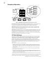
Figure 2 PROFIBUS compared with convetional comms. systems
PROFIBUS-DP distinguishes between master devices and slave devices. It allows slave devices
to be connected on a single bus thus eliminating considerable plant wiring typical with
conventional communications systems. The Figure above compares the two systems.
Master devices determine the data communication on the bus. A master can send messages
without an external request when it holds the bus access rights (the token). Masters are also
called active stations in the PROFIBUS protocol.
Slave devices are peripheral devices. Typical slave devices include input/output devices, valves,
motor drives and measuring transmitters. The 2408f and 2404f series Temperature Controllers
are intelligent slaves. This means they will only respond to a master when requested to do so.
PROFIBUS-DP is based around the idea of a ‘cyclical scan’ of devices on the network, during
which ‘input’ and ‘output’ data for each device is exchanged.
,22#'DWD#([FKDQJH
The process of reading the inputs and writing to the outputs is known as an I/O data exchange.
Typically, the parameters from each slave device will be mapped to an area of PLC input and
output registers, or a single function block, so that the controlling ladder logic or program
interfaces with the device as if it were an internally fitted module. It is NOT necessary,
therefore, for the programmer to know anything about the physical network. The process of
network configuration is usually performed using a PC based program which allows the devices
on the network to be defined and device parameters to be mapped into the PLC registers or
function blocks.
The cyclical scan occurs in the following order:
1. Values from each slave device, ‘Input Data’, are first scanned over the network into a predefined set of input registers in the master controller. Such values might be a set of digital
input readings for a digital input unit, or the measured temperature and alarm status from a
PID controller.
2. The master then runs its control program, (such as a ladder logic program) using the input
data read from the slave devices.
3. The master writes output values (output data) into a pre-defined set of output registers. For
example, one of the digital inputs read in the input data might be used to select one of a set of
setpoints to be sent to the PID controller.
4. These outputs are then written to each slave device, and the scan-process-write cycle repeats.
Typically no more than 32 bytes of input data and 32 bytes of output data are exchanged for each
device during the data exchange. Some PLC masters allow no more than this, although the
352),%860'3#&RPPXQLFDWLRQV#,QWHUIDFH#0#+$7968948334
6
PROFIBUS-DP standard provides the possibility of transferring 236 bytes in each direction.
The input and output data lengths for a given device are variable and it is possible to have
devices with only input data, only output data, or both.
The input and output data mixture used by a given slave device is defined by what is known as a
GSD file. See Chapter 5 for more details. For simple devices such as digital or analogue I/O
blocks, this is fixed. However, since more complex devices often have a much wider choice of
possible values to send, it is usually possible to edit the GSD file to change the mapping of
device parameters onto Profibus inputs or outputs. This is the case with most Eurotherm
implementations, which also allow access to parameter data not in the GSD Input/Output data
file. This is called Demand Data and is described further in Chapter 7.
The GSD file is imported into the PROFIBUS Master Network Configuration software before
the network is created.
NB:
PROFIBUS Input Data = Values sent from a device to a master controller or PLC,
PROFIBUS Output Data = Values sent from a master controller or PLC to a device.
3URGXFW#)HDWXUHV
• Suitable for use with:
584SV
590+
590+DRV
605A & B
605C
•
•
•
•
•
•
•
•
software version 4.x onwards
software version 5.x onwards
software version 5.x onwards
software version 4.x onwards
software version 4.x onwards
Hardware self-test
Connection using shielded, twisted-pair cable
LEDs to indicate board and communications status
Configured using Function Block inputs
Diagnostics using Function Block outputs
Automatic Baud Rate selection
Software-selectable Slave Address
Direct tag access for all drive parameters
3URGXFW#&RGH#DQG#&RQWHQWV
The Eurotherm Drives’ product is fully identified using an alphanumeric code which records
how the product was assembled, and its various settings when despatched from the factory.
The Technology Option can be supplied with the drive product, or supplied separately:
3URGXFW
3URGXFW#&RGH#ZKHQ
VXSSOLHG#ZLWK#WKH#'ULYH
3URGXFW#&RGH#ZKHQ
VXSSOLHG#VHSDUDWHO\
8;769
8;7692[[[[2[[[2[[[[2[[2[[[2352)
352)2[[2[[[2[[[
8;769
352)
$+7967:38334#0#SOXJ0LQ#7HFKQRORJ\#&DUG
8<3.
8<332[[[[2[[[2[[[[2[[2[[[2352)
352)2[[[2[[[
8<33
352)
93882352)233#0#SOXJ0LQ#7HFKQRORJ\#%R[
8<3.'59
<88.2[2[2[[[[2[[[
<88.
93882352)233#0#SOXJ0LQ#7HFKQRORJ\#%R[
938$#)#%
9382[[[2[[[2[2[2[[[6
62[[2[[[
938
93862352)233#0#SOXJ0LQ#7HFKQRORJ\#%R[
938&
938&2[[[[2[[[2[[[[2[[2[[[2352)
352)2[[2[[[2[[[
938&
352)
93882352)233#0#SOXJ0LQ#7HFKQRORJ\#%R[
352),%860'3#&RPPXQLFDWLRQV#,QWHUIDFH#0#+$7968948334
7
,QVWDOODWLRQ
:LULQJ#WKH#6\VWHP
:$51,1*$#
%HIRUH#LQVWDOOLQJ/#HQVXUH#WKDW#WKH#GULYH#DQG#DOO#ZLULQJ#LV#HOHFWULFDOO\#LVRODWHG#DQG
FDQQRW#EH#PDGH#´OLYHµ#XQLQWHQWLRQDOO\#E\#RWKHU#SHUVRQQHO1
:DLW#8#PLQXWHV#DIWHU#GLVFRQQHFWLQJ#SRZHU#EHIRUH#ZRUNLQJ#RQ#DQ\#SDUW#RI#WKH#V\VWHP#RU
UHPRYLQJ#WKH#FRYHUV#IURP#WKH#'ULYH1
The Profibus Technology Option is provided in one of two forms:
1. A plug-in Technology Box
2. A board-mounted Technology Card (584SV only)
It is operated as a 2-wire system:
• A 2-wire system can only be used in a network in which all devices use their tri-state
capability. Data flow is restricted, i.e. transmit and receive cannot be simultaneous (half
duplex).
1RWH=# ,W#LV#SRVVLEOH#WR#PDNH#VHULDO#FRPPXQLFDWLRQV#RSHUDWH#ZLWKRXW#DGKHULQJ#WR#WKH#IROORZLQJ
UHFRPPHQGDWLRQV/#KRZHYHU/#WKH#UHFRPPHQGDWLRQV#ZLOO#SURPRWH#JUHDWHU#UHOLDELOLW\1
&DEOH#6SHFLILFDWLRQ
Either of the two cable types detailed below can be used but we recommend Type A as it allows
higher speed and longer cable length.
7\SH#$#FDEOH
7\SH#%#FDEOH
&KDUDFWHULVWLF
,PSHGDQFH=
468#WR#498Ω#DW#D#IUHTXHQF\#RI#6#WR#530+]1
468#WR#498Ω#DW#D#IUHTXHQF\#RI
!433N+]
&DEOH
FDSDFLWDQFH=
?#63S)#SHU#PHWUH
W\SLFDOO\#?93S)#SHU#PHWUH
&RUH#GLDPHWHU=
PD[1#3167#PPò/#FRUUHVSRQGV#WR#$:*#55
PD[LPXP#3155PPò/
FRUUHVSRQGV#WR#$:*57
&DEOH#W\SH=
WZLVWHG#SDLU#FDEOH1#4[5#RU#5[5#RU#4[7#OLQHV
WZLVWHG#SDLU#FDEOH1#4[5#RU#5[5
RU#4[7#OLQHV
5HVLVWDQFH=
?#443Ω#SHU#NP
0
6KLHOGLQJ=
&RSSHU#VKLHOGLQJ#EUDLG#RU#VKLHOGLQJ#EUDLG
DQG#VKLHOGLQJ#IRLO
&RSSHU#VKLHOGLQJ#EUDLG#RU
VKLHOGLQJ#EUDLG#DQG#VKLHOGLQJ
IRLO
1RWH=# %HOGHQ#%63:<$#FDEOH#PHHWV#WKH#DERYH#VSHFLILFDWLRQ#IRU#7\SH#$/#EXW#WKHUH#DUH#RWKHUV1
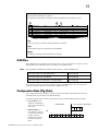
0D[LPXP#/LQH#/HQJWK#3HU#6HJPHQW
%DXG#UDWH#+NELW2VHF,
%DXG#UDWH
<19
4<15
<61:8
4;:18
833
4833
7\SH#$#FDEOH
4533P
4533P
4533P
4333P
733P
533P
7\SH#%#FDEOH
4533P
4533P
4533P
933P
533P
0
352),%860'3#&RPPXQLFDWLRQV#,QWHUIDFH#0#+$7968948334
8
(DUWKLQJ#WKH#6KLHOG
The PROFIBUS standard suggests that both ends of the transmission line should be connected to
safety earth. If you do this, ensure that differences in local earth potential do not allow
circulating currents to flow, as not only can these induce large common mode signals in the data
lines, but they can also produce potentially dangerous heating in the cable. If in doubt, earth the
shield at only one section of the network.
8VHU#&RQQHFWLRQV#WR#WKH#0DLQ#6HULDO#3RUW#+34,
The serial port on the Option allows the following Profibus links to be made.
3URILEXV
(OHFWULFDO#&RQQHFWLRQV
1XPEHU#RI#WUDQVPLWWHUV#DQG#WUDQVFHLYHUV
DOORZHG#SHU#GLIIHUHQWLDO#SDLU#RI#ZLUHV
0D[LPXP#FDEOH#OHQJWK
605A&B
Technology Box
50ZLUH#GLIIHUHQWLDO
65#WUDQVFHLYHUV
7333IW24533#PHWUHV
605C, 590+ and 590+DRV
Technology Box
TB1
584SV Technology Card
TB1
TB1
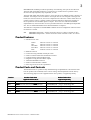
Terminal Block TB1
1 2 3 4 5 6
Figure 3 Option showing TB1
7HUPLQDWRUV
0Vext (1)
• If the drive is at the end of the network it
must have terminating resistors.
• All other drives in the system should not
have terminators.
Connect terminating resistors to the last drive
as shown opposite. (All resistors ±5%,
minimum ¼ Watt).
+5VDCext (2)
390 Ω
B-B' (3)
220 Ω
A-A' (4)
352),%860'3#&RPPXQLFDWLRQV#,QWHUIDFH#0#+$7968948334
390 Ω
9
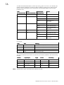
7HUPLQDO#%ORFN#+7%4,#&RQQHFWLRQV
7%4#7HUPLQDO
5HIHUHQFH
0HDQLQJ
4
39H[W
6LJQDO#UHIHUHQFH#IRU#352),%86
5
.89'&H[W
.89'&H[W283P$#VXSSO\#IRU#352),%86
6
%0%·
5HFHLYH27UDQVPLW#'DWD#3RVLWLYH
7
$0$·
5HFHLYH27UDQVPLW#'DWD#1HJDWLYH
8
576
)RU#FRQQHFWLQJ#UHSHDWHU#+77/,
9
*1'
*URXQG#FRQQHFWLRQ#IRU#(0&
5HSHDWHUV
RTS (Pin 5 , TB1) is a TTL level signal that can be connected to a repeater. Most repeaters
automatically switch between transmitting and receiving and so do not need this connection.
)LWWLQJ#DQG#&RQQHFWLQJ#WR#WKH#7HFKQRORJ\#%R[
Technology
Box
screen connections
605A & B
Captive Screw
Technology
Box
605C, 590+, 590+DRV (590+ 15A unit illustrated)
Figure 4 Plug-in Technology Boxes
:$51,1*$#
(QVXUH#WKDW#DOO#ZLULQJ#LV#LVRODWHG1
,03257$17=# 5HPHPEHU#WR#VHW#WKH#VZLWFK#SRVLWLRQV#RQ#WKH#',/#VZLWFK/#6:41
The Technology Option plugs into the right-hand position on the front of the drive, or in place of
the Operator Station/blank cover (605A & B only).
It can be used with the Operator Station fitted, but for the 605A & B unit you must mount the
Operator Station remotely using the Panel Mounting Kit with connecting lead (6052). The
connecting lead enters the 605 A & B drive through the gland plate.
• Remove the terminal cover and screws.
• On the 605A & B unit, plug the ribbon cable into the back of the Technology Box and into
the socket on the drive.
352),%860'3#&RPPXQLFDWLRQV#,QWHUIDFH#0#+$7968948334
:
• Click the Technology Box into place in the recess on the front of the drive. If provided,
secure in position by tightening the captive screw on the bottom right hand corner of the
Option.
• Make all user wiring connections. Refer to the Wiring Diagram.
• Re-fit the terminal cover securely with the screws.
&RQQHFWLQJ#WR#WKH#7HFKQRORJ\#&DUG#+8;769#RQO\,
The option is supplied as a “Technology Card”. This is factory-fitted to the control board inside
the drive.
When connecting to the Technology Card,
observe static control precautions.
:$51,1*$#
(QVXUH#WKDW#DOO#ZLULQJ#LV#LVRODWHG1
8;769#7\SHV#7/#8#)#9
Technology
Card
• Remove the terminal cover and screws.
,03257$17=# 5HPHPEHU#WR#VHW#WKH#VZLWFK#SRVLWLRQV
RQ#WKH#',/#VZLWFK/#6:41
Control Board
• Make all user wiring connections.
Refer to the Wiring Diagram.
• Re-fit the terminal cover securely with
the screws.
Terminal Cover
8;769#7\SHV#:/#;/#<#)#43
• Remove the bottom front cover.
,03257$17=# 5HPHPEHU#WR#VHW#WKH#VZLWFK#SRVLWLRQV#RQ
WKH#',/#VZLWFK/#6:41
• Make all user wiring connections. Refer
to the Wiring Diagram.
• Re-fit the terminal cover securely with
the screws.
Technology
Card
Control Board
Bottom Front Cover
352),%860'3#&RPPXQLFDWLRQV#,QWHUIDFH#0#+$7968948334
;
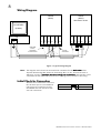
:LULQJ#'LDJUDP
DRIVE
(slave)
DRIVE
(slave)
last drive in chain
PLC/SCADA
(master)
TRANSMIT
A-A'
1
B-B'
GND
0V
2
+5V
0Vext DCext
3
4
5
6
B-B'
A-A'
RTS
GND
1
2
+5V
0Vext DCext
3
4
5
6
B-B'
A-A'
RTS
GND
390 W 220 W
605A & B
screen
connection
to earth screw
screen
connection
390W
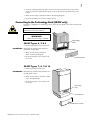
Figure 5 Typical Wiring Diagram
1RWH=# 7KH#GLDJUDP#DERYH#VKRZV#WKH#WHUPLQDO#EORFN#RULHQWDWLRQ#IRU#WKH#%$&.09,(:#
%$&.09,(:#RI#WKH
%$&.09,(:#
938#$#)#%#7HFKQRORJ\#%R[1#:KHQ#WKH#7HFKQRORJ\#%R[#LV#LQ0VLWX/#WKH#WHUPLQDO#RUGHU#LV
HIIHFWLYHO\#UHYHUVHG#0#UHPHPEHU#WKLV#ZKHQ#PDNLQJ#XVHU0FRQQHFWLRQV1
UHPHPEHU#WKLV#ZKHQ#PDNLQJ#XVHU0FRQQHFWLRQV1#1RWH#WKDW#WKH#VFUHHQ
UHPHPEHU#WKLV#ZKHQ#PDNLQJ#XVHU0FRQQHFWLRQV1
FRQQHFWLRQV#IRU#WKH#938$#)#%#WHUPLQDWH#DW#DQ#HDUWKLQJ#SLOODU#SURYLGHG#RQ#WKH#FDVLQJ1
,QLWLDO#&KHFN#IRU#&RQQHFWLRQ
With the correct connections to the active
PLC/SCADA supervisor, the MODULE
LED will be ON continuously and the
NETWORK LED will indicate the Idle
state with a short flash.
21
02'8/(#/('
6+257#)/$6+
1(7:25.#/('
352),%860'3#&RPPXQLFDWLRQV#,QWHUIDFH#0#+$7968948334
<
8QGHUVWDQGLQJ#WKH#/('#,QGLFDWLRQV
605A&B
Technology Box
605C, 590+ and 590+DRV
Technology Box
584SV Technology Card
RUN
HEALTH
MODULE
NETWORK
MODULE
TB1
NETWORK
NETWORK
MODULE
TB1
Figure 6 Technology Option LEDs
HINT:
The general rule for LED indications is
“ON IS GOOD, OFF IS BAD”
+HDOWK#DQG#5XQ#/('V
938$#)#%#7HFKQRORJ\#%R[
These LEDs reproduce the indications of the LEDs on the drive that are hidden by the fitting of
the Technology Box.
8;769#7HFKQRORJ\#&DUG#DQG#938&/#8<3./#8<3.'59#7HFKQRORJ\#%R[
The board does not have its own Health or Run LEDs. The LEDs are either on the Operator
Station or blank cover.
1HWZRUN#DQG#0RGXOH#/('#,QGLFDWLRQV
1HWZRUN#/('
0RGXOH#/('
,QGLFDWHV#WKH#VWDWH#RI#WKH
FRQQHFWHG#QHWZRUN1
,QGLFDWHV#WKH#VHW0XS#VWDWH#RI#WKH#7HFKQRORJ\#%R[22SWLRQ1
7KH#VWDWHV#LQGLFDWHG#DUH#WKRVH#SURGXFHG#E\#WKH#)$8/7
SDUDPHWHU#RI#WKH#7(í,21#IXQFWLRQ#EORFN1
/('#,QGLFDWLRQ
'HVFULSWLRQ
)$8/7#3DUDPHWHU
'HVFULSWLRQ
2))
'LVDEOHG#RU#%DXG#VHDUFK
+$5':$5(
+DUGZDUH#)DXOW#0#H[WHUQDO
6+257#)/$6+
:DLW#3DUDPHWHULVDWLRQ
6(/)#7(67
+DUGZDUH#IDXOW#0#LQWHUQDO
)/$6+
:DLW#&RQILJXUDWLRQ
7<3(#0,60$7&+
:URQJ#W\SH#RU#GLVDEOHG
/21*#)/$6+
'DWD#H[FKDQJH#ZLWK#HUURU
3$5$0(7(5
6HW0XS#IDXOW/#SDUDPHWHU#YDOXHV#RXW0
RI0UDQJH
21
'DWD#H[FKDQJH
121(
9DOLG#VHW0XS/#UHDG\#IRU#H[WHUQDO
FRPPXQLFDWLRQV
1RWH=# 7KH#1(7:25.#/('#LV#DOZD\V#LQ#WKH#2))#VWDWH#ZKHQ#WKH#02'8/(#/('#LV#QRW
QRW#21
QRW
FRQWLQXRXVO\/#LQGLFDWLQJ#WKDW#WKH#2SWLRQ#LV#QRW#UHDG\#IRU#H[WHUQDO#FRPPXQLFDWLRQV1
352),%860'3#&RPPXQLFDWLRQV#,QWHUIDFH#0#+$7968948334
43
,QLWLDO#6HW0XS#IRU#3URILEXV
&RQILJXULQJ#WKH#'ULYH
00,#0HQX#0DS
1RQ0VSHFLILF#00,#YLHZ
4
SETUP PARAMETERS
5
FUNCTION BLOCKS
6
SERIAL LINKS
7
TEC OPTION
TEC OPTION TYPE
TEC OPTION IN 1
TEC OPTION IN 2
TEC OPTION IN 3
TEC OPTION IN 4
TEC OPTION IN 5
TEC OPTION FAULT
TEC OPTION VER
TEC OPTION OUT 1
TEC OPTION OUT 2
00,#0HQX#0DS
352),%86#'3#YLHZ
Using the Operator Station (MMI) or
other suitable PC programming tool,
the TEC OPTION function block
requires configuring before the
PROFIBUS option can be used.
The parameter names/functions in this
function block are inter-dependant and
will change with different parameter
values and the various Options that can
be fitted.
The top Function Block diagram shows
the ConfigEd Lite parameter names,
which are also displayed on the MMI if
no Option is fitted or an incorrect TYPE
is selected for the fitted Option.
ConfigEd Lite is Eurotherm Drives’
Windows-based block programming
software.
TEC OPTION
FAULT
VERSION
OUTPUT 1
OUTPUT 2
NONE
0
0
0
0
0
–
–
–
–
–
–
[750]
[751]
[752]
[753]
[754]
[755]
[756]
[757]
[758]
[759]
TYPE
INPUT 1
INPUT 2
INPUT 3
INPUT 4
INPUT 5
–
–
–
–
–
–
–
–
–
–
NONE
0000
0000
0000
Non-specific ConfigEd-Lite view
TEC OPTION
PROFIBUS DP
0
0
0
0
0
–
–
–
–
–
–
FAULT [756]
VERSION [757]
NETWORK STATE [758]
INT DIAGNOSTIC [759]
[750] TYPE
[751] ADDRESS
[752] EXT DIAGNOSTIC
[753] INT DIAG SELECT
[754] UNUSED 1
[755] UNUSED 2
– NONE
– 0101
– DISABLED
– 0000
–
–
–
–
–
–
When the TYPE parameter is set to
PROFIBUS DP ConfigEdLite view
display PROFIBUS, the function block
parameters take on new identities, as shown in the lower Function Block diagram.
4
SETUP PARAMETERS
5
FUNCTION BLOCKS
6
SERIAL LINKS
6HOHFWLQJ#352),%86#'3
7
TEC OPTION
(Select Advanced view level on the Operator Station and view the TEC OPTION function
block).
TYPE
ADDRESS
EXT DIAGNOSTIC
INT DIAG SELECT
UNUSED 1
UNUSED 2
FAULT
VERSION
NETWORK STATE
INT DIAGNOSTIC
SERIAL LINKS is at
Menu Level 1 for the
590+ and 590+DRV.
• Select PROFIBUS DP in the TYPE parameter
• Enter a slave ADDRESS
• Check the FAULT parameter for error messages, rectify if necessary
When setting values for parameters from ConfigEd Lite (or other suitable PC programming tool)
you are able to select any value in the parameter’s range, i.e. -32768 to 32767. If the value is
incorrect, i.e. it doesn’t correspond to a value that can be set using the MMI, then the FAULT
output parameter will be set to PARAMETER.
00,#3DUDPHWHU#'HVFULSWLRQV#IRU#(,#%,6<1&+
Range: Enumerated - see below
TYPE
Selects the type of Technology Option card.
Enumerated Value : Technology Option
3#=#121(
4#=#567;8
5#=#352),%86#'3
6#=#/,1.
7#=#'(9,&(1(7
8#=#&$123(1
9#=#/21:25.6
:#=#7<3(#:
Range: 0 to 125
ADDRESS
The PROFIBUS slave address. Note that addresses 0, 1 and 2 are usually reserved for
PROFIBUS Masters and so should be avoided.
352),%860'3#&RPPXQLFDWLRQV#,QWHUIDFH#0#+$7968948334
44
Range: 0 to FFFF
EXT DIAGNOSTIC
(External Diagnostic) The value of this parameter appears as the 2nd and 3rd bytes of the
application specific diagnostics to the master. Refer to “PROFIBUS Diagnostics”, page 20. This
provides a simple way to implement user defined trips or exceptions.
Range: 0 to 29999
INT DIAG SELECT
(Internal Diagnostic Select) Refer to “Internal Diagnostics”, page 22.
UNUSED 1
Reserved for future use.
Range: 0 to FFFF
UNUSED 2
Reserved for future use.
Range: 0 to FFFF
FAULT
The fault state of the Technology Option.
Range: Enumerated - see below
0 : NONE
1 : PARAMETER
2 : TYPE MISMATCH
3 : SELF TEST
4 : HARDWARE
5 : MISSING
no faults
parameter out-of-range
TYPE parameter not set to PROFIBUS DP
hardware fault - internal
hardware fault - external
no option fitted
Also refer to Network and Module LED Indications, page 9.
Range: 0000 to FFFF
VERSION
The version of the Technology Option card. If no option is fitted then the version is reset to zero.
Range: Enumerated - see below
NETWORK STATE
The network state of the Technology Option card. Refer to “Network and Module LED
Indications” page 9 for further information.
Enumerated Value : Fault State
0 : DATA EXCHANGE
1 : DATA EX ERROR
2 : WAIT CONFIG
3 : WAIT PARAM
4 : BAUD SEARCH
5 : DISABLED
DATA EXCHANGE
Data Exchange mode. The parameterisation and configuration have been accepted and the slave
is exchanging user data with the master.
DATA EX ERROR
Data Exchange mode, as above, but with read/write error(s). This indicates that at least one of the
parameters being read or written is failing, for example writing a value out of range.
WAIT CONFIG
Waiting for configuration. The parameterisation from the master has been accepted and is now
waiting for the Master to send valid configuration data.
WAIT PARAM
Waiting for parameterisation. The slave has detected communications at a valid baud rate and is
waiting for the master to send valid parametrisation data.
BAUD SEARCH
The slave has not detected valid communications.
DISABLED
The interface is disabled. The reason for this is given by the FAULT parameter.
Range: 0000 to FFFF
INT DIAGNOSTIC
Refer to “Internal Diagnostics”, page 22.
352),%860'3#&RPPXQLFDWLRQV#,QWHUIDFH#0#+$7968948334
45
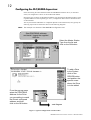
&RQILJXULQJ#WKH#3/&26&$'$#6XSHUYLVRU
Other than setting the TEC OPTION TYPE and ADDRESS within the Drive, as described
earlier, all configuration is done via the Profibus-DP-Master.
During the start-up phase, the Profibus-DP-Master will check that the Profibus-DP-Slave at the
requested address is of the required type. If it is, Configuration Data and User Parameter Data
are downloaded.
The way the Profibus-DP-Master is configured depends on the manufacturer, but typically the
following steps must be followed as shown in the following diagrams.
1RWH=# 7KH#H[DPSOH#XVHV#6LHPHQV#&20#352),%86#FRQILJXUDWLRQ#WRRO1
Start PROFIBUS software
and install / import the supplied
GSD file
Select the Master Station
Type from the list and
click on the OK button
To add a Drive
to the System
click on the
DRIVES button
and position the
special cursor
where the Drive
is to be added
From the pop-up menu
select the PROFIBUS
Address for the Drive
you are adding to match
the Drive's configured
address and then
click on the OK button
next diagram
Figure 7 Typical Configuration Tool Procedure
352),%860'3#&RPPXQLFDWLRQV#,QWHUIDFH#0#+$7968948334
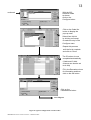
46
With the 605
selection made
as shown
click on the
Configure button
continued
Click on the Order No.
button to display the
pop-up menu
Select from this list
by clicking on Accept
to make an entry in the
Configure menu
Repeat this process
until the list is complete
and click on Close
The ID column is now
completed automatically
(I Addr and O Addr.
columns can also be set
to do this)
Fill in the Remarks column
for information and then
click on the OK button
Click on the
Parameterize button
next diagram
Figure 8 Typical Configuration Tool Procedure
352),%860'3#&RPPXQLFDWLRQV#,QWHUIDFH#0#+$7968948334
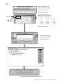
47
Alternative view of menu below
taken from another configuration tool
Enter the Tag No's in Hex
They are entered in pairs
i.e. 3 & 4, 5 & 6 etc.
Note that leading zeros
are omitted in the menu
thus the entry for 4 is actually
continued
`0F' and not `F' as shown, e.g.
0, 1 & 2 are
reserved
(always 00)
3&4
= 01 0F
=
271
5&6
= 01 0D
=
269
7&8
= 01 10
=
272
9 & 10
= 00 FF
=
255
Click on the OK button
Click on the OK button
to see the System menu
with the added Drive
Click on DRIVES to repeat the process
and add another Drive to the System
Figure 9 Typical Configuration Tool Procedure
352),%860'3#&RPPXQLFDWLRQV#,QWHUIDFH#0#+$7968948334
48
By referring to the Parameter Specification Table in the main Product Manual, you can enter
the parameter information you require.
The Parameter Specification Table provides the information in the following way:
7DJ
+00,,#1DPH
%ORFN
7\SH
5DQJH
,'
47
$,1#4#6&$/(
$1$/2*#,1387#4
,17
0633133#WR#633133#(
3H
48
$,1#4#2))6(7
$1$/2*#,1387#4
,17
0633133#WR#633133#(
3I
49
$,1#4#9$/8(
$1$/2*#,1387#4
,17
[[[1[[#(
3J
4:
$,1#4#%5($.#9$/
$1$/2*#,1387#4
,17
0633133#WR#633133#(
3K
4;
$,1#4#%5($.
$1$/2*#,1387#4
%22/
)$/6(#2#758(
3L
54
$,1#5#%5($.#(1%/
$1$/2*#,1387#5
%22/
)$/6(#2#758(
3O
55
$,1#5#7<3(
$1$/2*#,1387#5
(180
6DPH#DV#WDJ#46
3P
56
$,1#5#6&$/(
$1$/2*#,1387#5
,17
0633133#WR#633133#(
3Q
1RWHV
2XWSXW
2XWSXW
:
Example only
7DJ
The Tag column provides the unique parameter tag number.
7\SH
All parameter Types are supported, except STRING.
5DQJH
The Range column provides information on scaling.
*6'#)LOHV
Three GSD files are provided for use with this option. These are available on request or can be
downloaded from the Profibus Interne site (http://www.profibus.com).
1RWH=# 7KH#UHJLVWHUHG#LGHQWLILFDWLRQ#QXPEHU#IRU#WKH#RSWLRQ#LV#497<#+KH[DGHFLPDO,1
'HYLFH#GHVFULSWLRQ#IRU#WKH#938$/#%#)#&
HXUR497<1JVG
'HYLFH#GHVFULSWLRQ#IRU#WKH#8;769
HXU[497<1JVG
'HYLFH#GHVFULSWLRQ#IRU#WKH#8<3.#DQG#8<3.'59
HXU\497<1JVG
The contents of the above files are the same except for the Model Name. This is to allow the
correct description to appear on the Profibus configuration tool.
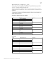
&RQILJXUDWLRQ#'DWD#+&IJB'DWD,
The Configuration Data (Cfg_Data) is used to specify the number of parameters that are to be
read and written as part of the cyclic Data Exchange.
The Data Exchange either consists of just Process Data, or Demand Data and Process Data.
• Process Data is the
fixed set of parameters
that are to be transferred
each cycle.
• Demand Data is 8
reserved bytes (octets)
to support a messaging
system, allowing
random access to any
parameter within the
drive.
352),%860'3#&RPPXQLFDWLRQV#,QWHUIDFH#0#+$7968948334
Demand Data
Process Data (2 Parameters)
0
3
8
11
OR
0
7
49
To enable the Demand Data feature, the first byte of Cfg_Data is set to 0x73 (115 decimal). The
number of Inputs and Outputs in the Process Data is defined by setting bytes to either 0x50 (80
decimal), 0x60 (96 decimal) or 0x70 (112 decimal). The maximum number of Process Data
parameters is 30.
,QGH[
+1R#'HPDQG#'DWD,
,QGH[
+:LWK#'HPDQG#'DWD,
,GHQWLILHU#%\WH
++H[DGHFLPDO,
$FWLRQ
0
3
3[:6
(QDEOH#'HPDQG#'DWD
3
4
3[83
5HDG#4VW#3DUDPHWHU
3[93
:ULWH#4VW#3DUDPHWHU
3[:3
5HDG2:ULWH#4VW
3DUDPHWHU
3[83
5HDG#5QG#3DUDPHWHU
3[93
:ULWH#5QG#3DUDPHWHU
3[:3
5HDG#DQG#:ULWH#5QG
3DUDPHWHU
4
5
HWF
HWF
HWF
HWF
5<
63
3[83
5HDG#63WK#3DUDPHWHU
3[93
:ULWH#63WK#3DUDPHWHU
3[:3
5HDG#DQG#:ULWH#63WK
3DUDPHWHU
For example:
,QGH[
'DWD
0HDQLQJ
3
3[93
4VW#3DUDPHWHU#2XWSXW##+1R#'HPDQG#'DWD,
4
3[93
5QG#3DUDPHWHU#2XWSXW
5
3[83
6UG#3DUDPHWHU#,QSXW
6
3[83
7WK#3DUDPHWHU#,QSXW
The supported Identifier Byte formats are defined by the Profibus Standard to have the following
meaning:
,GHQWLILHU
,QSXW22XWSXW
/HQJWK
)RUPDW
&RQVLVWHQF\
3[83
,QSXW
4
:RUG
1RQH
3[93
2XWSXW
4
:RUG
1RQH
3[:3
,QSXW02XWSXW
4
:RUG
1RQH
3[:6
,Q#DQG#2XW
7
:RUG
1RQH
1RWH=# $OO#SDUDPHWHU#YDOXHV#DUH#WUDQVIHUUHG#DV#:RUGV#+5#RFWHWV,1
352),%860'3#&RPPXQLFDWLRQV#,QWHUIDFH#0#+$7968948334
4:
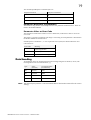
8VHU#3DUDPHWHU#'DWD#+8VUB3UPB'DWD,
The Usr_Prm_Data is used to specify the Tag numbers of the parameters that are to be read or
written as Process Data. Each parameter is represented by 2 bytes in the Usr_Prm_Data, these
specify the Tag number in High-Byte/Low-Byte order.
The first 3 bytes of the Usr_Prm_Data are reserved for the future implementation on the DPV1
Profibus extensions. These must be set to zero. The High-Byte of the first Tag number must be in
the 4th byte.
The Usr_Prm_Data may be up to 63 Bytes long. If less than 63 Bytes are sent, the length must be
3 x 2n, where n is a number between 0 and 30. Unused Bytes must be set to zero and must be at
the end of the Tag declarations.
The number of Tags declared must match the number of Inputs, Outputs and Input-Outputs
declared to be in the Process Data by the Cfg_Data.
,QGH[
'DWD
3DUDPHWHU
3
5HVHUYHG#IRU#'394
4
5HVHUYHG#IRU#'394
5
5HVHUYHG#IRU#'394
6
+LJK0%\WH
7
/RZ0%\WH
8
+LJK0%\WH
9
/RZ0%\WH
:
+LJK0%\WH
;
/RZ0%\WH
HWF
HWF
HWF
94
+LJK0%\WH
63WK
95
/RZ0%\WH
4VW
5QG
6UG
For example:
,QGH[
'DWD#++H[DGHFLPDO,
3DUDPHWHU
3
3[33
5HVHUYHG
4
3[33
5
3[33
6
3[34
7
3[3)
8
3[34
9
3[3'
:
3[34
;
3[43
<
3[33
43
3[))
352),%860'3#&RPPXQLFDWLRQV#,QWHUIDFH#0#+$7968948334
7DJ#1XPEHU#5:4
7DJ#1XPEHU#59<
7DJ#1XPEHU#5:5
7DJ#1XPEHU#588
4;
When entered using a Profibus configuration tool, the above example would typically be
displayed as:
00,00,00,01,0F,01,0D,01,10,00,FF
Some configuration tools will alway display the number of bytes declared in the supplied GSD,
in this case 63. So the above example will appear as:
00,00,00,01,0F,01,0D,01,10,00,FF,00,00,00,00,00,00,00.....
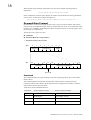
'HPDQG#'DWD#3URWRFRO
Demand Data is a sub-protocol using the first 8 bytes (octets) in both the request and response
message of the cyclic Data Exchange. It allows random read/write access to any parameter within
the Drive. It is enabled by the Profibus-DP- Master setting the first byte of the Cfg_Data to 0x73.
(See Chapter 6, Configuration.)
The sub-protocol consists of 3 parts:
• Command
• Parameter Reference (Tag Number)
• Parameter Value or Error Code
Byte
0
1
2
Cmd / Tag
Bit
15
3
4
5
7
Value
Reserved
12
6
10
11
0
Parameter Tag Number
Command
Reserved
&RPPDQG
The Command field in the request message selects the required operation. This is either None,
Read or Write.
The Command field in the response message either confirms that no operation has been
requested, indicates that a Read or Write request has been completed successfully or indicates
that a Read or Write request has failed.
Valid values for the Command field are:
&RPPDQG
5HTXHVW#+0DVWHU#WR#6ODYH,
5HVSRQVH#+6ODYH#WR#0DVWHU,
3
1R#&RPPDQG
$FNQRZOHGJH#1R#&RPPDQG
4
5HDG#5HTXHVW
$FNQRZOHGJH#7UDQVIHU
5
:ULWH#5HTXHVW
00
:
00
5HMHFW#5HTXHVW
352),%860'3#&RPPXQLFDWLRQV#,QWHUIDFH#0#+$7968948334
4<
The valid Request/Response Command pairs are:
5HTXHVW#&RPPDQG
5HVSRQVH#&RPPDQG
3
3
4
4#RU#:
5
4#RU#:
3DUDPHWHU#5HIHUHQFH#+7DJ#1XPEHU,
The Parameter Tag Number is the unique reference to a parameter within the Drive. These are
listed in the Product Manual.
3DUDPHWHU#9DOXH#RU#(UURU#&RGH
The Value/Error Code field is used to receive a Read value, send a Write value or receive an
error code.
The Value is a signed or unsigned 16-bit integer. The scaling for each parameter is described in
the Product Manual for the host Drive.
If the Response Command is 7, i.e. the request has been rejected, this field contains the error
code. These are:
(UURU#&RGH
0HDQLQJ
3
,QYDOLG#7DJ#1XPEHU
4
5HDG#2QO\#3DUDPHWHU
5
9DOXH#8QGHU22YHU05DQJH
'DWD#(QFRGLQJ
All parameter values are transferred in the Data Exchange telegram as Words (2 octets). The
most significant octet is transmitted first, e.g.
7\SH
9DOXH
+GHFLPDO,
7UDQVPLWWHG#9DOXH
+KH[DGHFLPDO,
,17
633133
:863
,17
0633133
;$'3
%22/
)$/6(
3333
%22/
758(
3334
1RWH=# 7KH#GHFLPDO#SRLQW#SRVLWLRQ#LV#QRW#WUDQVPLWWHG1#5HIHU#WR#WKH#3URGXFW#PDQXDO#IRU#WKH#FRUUHFW
VFDOLQJ1
352),%860'3#&RPPXQLFDWLRQV#,QWHUIDFH#0#+$7968948334
53
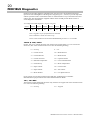
352),%86#'LDJQRVWLFV
Profibus DP provides diagnostic information for each slave unit. The Profibus Technology
Option uses the 'ExtDiagData' of the diagnostic telegram (bytes 7, 8 and 9) to provide Trip status
and user specified events. The Profibus master is notified whenever any of the monitored events
change state. The documentation supplied with the master should provide details on how to
access diagnostic information.
An example 605A & B diagnostic response telegram:
Octet 1
Octet 2
Octet 3
Octet 4
Octet 5
Octet 6
Octet 7
Octet 8
00
0C
00
01
16
49
04
01
Octet 9 Octet 10
6A
B5
Octet 7 signifies 4 bytes of information is included.
Octet 8 indicates a "Link Overvolts" Trip
Octets 9 and 10 indicate that the EXT DIAGNOSTIC parameter is set to 6AB5.
938$#)#%/#938&/#8;769=
Octet 8, bits 0 to 4, contain the reason why the drive has tripped. (Bits 5 to 7 are reserved for
future use.) The value contained in bits 0 to 4 have the following meaning:
0 = No Trip
9 = I*t
1 = Link Overvolts
10 = Brake Resistor
2 = Link Undervolts
11 = Brake Switch
3 = Link Overcurrent
12 = Operator Station
4 = Heatsink Temperature
13 = Lost Communications
5 = External Trip
17 = Motor Temperature
6 = Input 1 Break
18 = Current Limit
7 = Input 2 Break
20 = 24V Failure
8 = Motor Stalled
21 = Low Speed Current
Octets 9 and 10 are the most significant byte and least significant byte of the EXT
DIAGNOSTIC input parameter of the TEC OPTION Function Block.
8<3./#8<3.'59=
The interface cannot distinguish the reason why the drive has tripped. The value contained in bits
0 to 4 have the following meaning:
0 = No Trip
31 = Tripped
352),%860'3#&RPPXQLFDWLRQV#,QWHUIDFH#0#+$7968948334
54
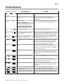
7URXEOHVKRRWLQJ
1(7:25.
02'8/(
&DXVH26\PSWRP
1R#SRZHU#DW#WKH#GULYH1
5HPHG\
&KHFN#DQG#DSSO\#SRZHU#WR#WKH#GULYH1
+2)),
7HFKQRORJ\#%R[22SWLRQ#QRW#LQVWDOOHG &KHFN#FRQQHFWLRQV#EHWZHHQ#7HFKQRORJ\
FRUUHFWO\1
%R[22SWLRQ#DQG#GULYH1#2Q#938$#)#%/#FKHFN#WKH
ULEERQ#FDEOH1
+DUGZDUH#IDXOW1
,I#+($/7+#DQG#581#/('6#DUH#2))/#UHSODFH#WKH
938$#)#%#:$51,1*=#5HPRYH#WKH GULYH/#HOVH#UHSODFH#WKH#7HFKQRORJ\#%R[22SWLRQ1
WHUPLQDO#FRYHU#DQG#WKH#7HFKQRORJ\
%R[#ZKLOVW#FRQQHFWHG#WR#VHH#WKH
GULYH·V#+($/7+#DQG#581#/('V1
%(:$5(#2)#(/(&75,+2&.1
7KH#VHOI0WHVW#KDV#IDLOHG1
5HSODFH#WKH#7HFKQRORJ\#%R[22SWLRQ1
,QFRUUHFW#7HFKQRORJ\#%R[22SWLRQ
ILWWHG#RU#VHOHFWHG1
)LW#WKH#FRUUHFW#7HFKQRORJ\#%R[22SWLRQ#RU#VHOHFW#WKH
PDWFKLQJ#YDOXH#IRU#WKH#7<3(#SDUDPHWHU#LQ#WKH#7(&
237,21#IXQFWLRQ#EORFN1#+7<3(# #352),%86#'3,1
6HW0XS#IDXOW1#$#7(í,21
SDUDPHWHU#LV#RXW0RI0UDQJH1
6HOHFW#WKH#FRUUHFW#YDOXH#IRU#WKH#SDUDPHWHU#LQ#WKH
7(í,21#IXQFWLRQ#EORFN1
1R#FRPPXQLFDWLRQV#RU#LQWHUPLWWHQW
IDLOXUH
&KHFN#ZLULQJ/#YHULI\LQJ#WKH#FRQWLQXLW\#RI#$#DQG#%
FRQQHFWLRQV#WR#WKH#PDVWHU/#DQG#HQVXUH#WKDW#WKH
FRUUHFW#WHUPLQDOV#KDYH#EHHQ#XVHG1#3D\#SDUWLFXODU
DWWHQWLRQ#WR#WKH#LQWHJULW\#RI#WKH#VFUHHQLQJ1
1R#FRPPXQLFDWLRQV#RU#LQWHUPLWWHQW
IDLOXUH
(QVXUH#WKDW#WKH#PD[LPXP#OLQH#OHQJWK#RI
WUDQVPLVVLRQ#OLQH#KDV#QRW#EHHQ#H[FHHGHG#IRU#WKH
%DXG#UDWH#LQ#XVH1#5HIHU#WR#´0D[LPXP#/LQH#/HQJWK
3HU#6HJPHQWµ/#SDJH#71
1R#FRPPXQLFDWLRQV#RU#LQWHUPLWWHQW
IDLOXUH
(QVXUH#WKDW#WKH#ODVW#XQLW#RQ#WKH#WUDQVPLVVLRQ#OLQH#LV
WHUPLQDWHG#FRUUHFWO\1#1RWH#WKDW#VRPH#HTXLSPHQW
KDV#EXLOW0LQ#UHVLVWRUV##ZKLFK#PD\#EH#VZWLFKHG#LQ#DQG
RXW#RI#FLUFXLW1
:DLWQJ#IRU#YDOLG#3DUDPHWHULVDWLRQ
GDWD
&KHFN#WKH#VODYH#$''5(661#&KHFN#WKDW#LW#LV#XQLTXH1
:DLWQJ#IRU#YDOLG#3DUDPHWHULVDWLRQ
GDWD
(QVXUH#WKDW#WKH#QHWZRUN#KDV#EHHQ#FRUUHFWO\
FRQILJXUHG#DQG#WKDW#WKH#FRQILJXUDWLRQ#KDV#EHHQ
FRUUHFWO\#GRZQORDGHG#WR#WKH#PDVWHU1
:DLWQJ#IRU#YDOLG#3DUDPHWHULVDWLRQ
GDWD
9HULI\#WKDW#WKH#*6'#ILOH#EHLQJ#XVHG#LV#FRUUHFW#E\
ORDGLQJ#LW#LQWR#WKH#*6'#ILOH#FRQILJXUDWRU#WR#FKHFN
WKH#IRUPDW1
:DLWLQJ#IRU#YDOLG#&RQILJXUDWLRQ#GDWD 5HIHU#WR#´,QWHUQDO#'LDJQRVWLFVµ/#SDJH#551
5HDG2:ULWH#IDLOXUH
5HIHU#WR#´,QWHUQDO#'LDJQRVWLFVµ/#SDJH#551
7KH#XQLW#VKRXOG#QRZ#EH#ZRUNLQJ1
,I#WKHUH#LV#VWLOO#D#SUREOHP/#SOHDVH#FKHFN#\RXU#7DJ
QXPEHUV1
352),%860'3#&RPPXQLFDWLRQV#,QWHUIDFH#0#+$7968948334
55
,QWHUQDO#'LDJQRVWLFV
Two parameters of the TEC OPTION function block provide diagnostic information:
1. The NETWORK STATE parameter (and the Technology Option’s LEDs) indicates the area
the problem is in.
2. The INT DIAGNOSTIC parameter allows access to internal network diagnostic information.
(The INT DIAG SELECT parameter selects what information will be output as the INT
DIAGNOSTIC parameter).
,17#',$*#6(/(&7#3DUDPHWHU#9DOXHV
3
6ODYH#&RQILJXUDWLRQ#HUURU1#8VHG#ZKHQ#VWXFN#LQ#WKH#:$,7#3$5$0#RU#:$,7#&21),*#VWDWHV1
3333
1R#HUURU1
3345
3DUDPHWHULVDWLRQ#WHOHJUDP#WRR#ORQJ1
3346
3DUDPHWHULVDWLRQ#WHOHJUDP#LV#D#EDG#OHQJWK1#,I#8VHUB3UPB'DWD#LV#SUHVHQW/#LW#PXVW#EH#RI
OHQJWK#6#.5Q/#ZKHUH#Q#LV#D#YDOXH#3#WR#631
3347
7KH#OLVW#RI#WDJ#QXPEHUV#LQ#WKH#8VU03UPBGDWD#FRQWDLQV#D#]HUR1#=HUR#7DJ#QXPEHUV#DUH#RQO\
DOORZHG#DW#WKH#HQG#RI#WKH#OLVW1
3354
7KH#&RQILJXUDWLRQ#WHOHJUDP#LV#RI#]HUR#OHQJWK1
3355
7KH#&RQILJXUDWLRQ#WHOHJUDP#LV#WRR#ORQJ1#7KH#PD[LPXP#OHQJWK#LV#64/#L1H1#FRQILJXUDWLRQ#IRU
63#LQSXWV/#RXWSXWV#RU#LQSXW0RXWSXWV/#SOXV#'HPDQG#'DWD1
3356
7KH#&RQILJXUDWLRQ#WHOHJUDP#FRQWDLQV#DQ#XQVXSSRUWHG#LGHQWLILHU#E\WH1#6HH#&RQILJXUDWLRQ
'DWD#VHFWLRQ1
3357
7KH#&RQILJXUDWLRQ#WHOHJUDP#FRQWDLQV#WRR#IHZ#LGHQWLILHU#E\WHV1#([FOXGLQJ#WKH#'HPDQG#'DWD
LGHQWLILHU#E\WH/#LI#SUHVHQW/#WKH\#PXVW#PDWFK#WKH#TXDQWLW\#RI#7DJV#GHFODUHG#LQ#WKH
3DUDPHWHULVDWLRQ#WHOHJUDP1
3358
7KH#&RQILJXUDWLRQ#WHOHJUDP#FRQWDLQV#WRR#PDQ\#LGHQWLILHU#E\WHV1#6HH#DERYH1
433#WR#45<
'LVSOD\V#7DJ#QXPEHU#+LQ#KH[DGHFLPDO,#RI#SDUDPHWHU#3#WR#5</#H1J1#VHWWLQJ#,17#',$*#6(/(&7#WR#434
ZLOO#VKRZ#WKH#7DJ#QXPEHU#RI#WKH#5QG#SDUDPHWHU1
533#WR#55<
'LVSOD\V#DFFHVV#PRGH#IRU#SDUDPHWHU#3#WR#5<1
633#WR#65<
3334
,QSXW#WR#PDVWHU/#L1H1#UHDG1
3335
2XWSXW#IURP#PDVWHU/#L1H1#ZULWH1
3336
,QSXW#DQG#RXWSXW/#L1H1#ERWK#UHDG#DQG#ZULWH1
'LVSOD\V#DFFHVV#HUURU#IRU#SDUDPHWHU#3#WR#5<1
3333
1R#HUURU1
3334
'DWD#RXW#RI#UDQJH1#7KH#YDOXH#EHLQJ#ZULWWHQ#E\#WKH#PDVWHU#LV#HLWKHU#OHVV#WKDQ#WKH#ORZ#OLPLW#RU
JUHDWHU#WKDQ#WKH#KLJK#OLPLW#IRU#WKH#VSHFLILHG#SDUDPHWHU1
3335
5HDG#RQO\1#7KH#PDVWHU#LV#DWWHPSWLQJ#WR#ZULWH#WR#D#UHDG0RQO\#SDUDPHWHU1
3336
1RW#6WRS#PRGH1#7KH#PDVWHU#LV#DWWHPSWLQJ#WR#ZULWH#WR#D#SDUDPHWHU#ZKLFK#FDQ#RQO\#EH
XSGDWHG#ZKHQ#WKH#GULYH#LV#LQ#WKH#6WRS#PRGH/#EXW#LW#LV#LQ#WKH#5XQ#PRGH1
3337
1RW#&RQILJXUDWLRQ#PRGH1#7KH#PDVWHU#LV#DWWHPSWLQJ#WR#ZULWH#WR#D#SDUDPHWHU#ZKLFK#FDQ#RQO\
EH#XSGDWHG#ZKHQ#WKH#GULYH#LV#LQ#WKH#&RQILJXUDWLRQ#PRGH/#EXW#LW#LV#LQ#WKH#QRUPDO#RSHUDWLQJ
PRGH1
3338
8QVXSSRUWHG#W\SH1#7KH#PDVWHU#LV#DWWHPSWLQJ#WR#UHDG#RU#ZULWH#D#SDUDPHWHU#RI#D#W\SH#ZKLFK
LV#QRW#VXSSRUWHG#E\#WKLV#LPSOHPHQWDWLRQ#RI#WKH#3URILEXV/#L1H1#W\SH#675,1*1
3339
,QYDOLG#7DJ#QXPEHU1#7KH#PDVWHU#LV#DWWHPSWLQJ#WR#UHDG#RU#ZULWH#D#SDUDPHWHU#WKDW#GRHV#QRW
H[LVW1
733#WR#75<
'LVSOD\V#ODVW#UHDG#YDOXH#+LQ#KH[DGHFLPDO,#IRU#SDUDPHWHU#3#WR#5<1
833#WR#85<
'LVSOD\V#ODVW#ZULWH#YDOXH#+LQ#KH[DGHFLPDO,#IRU#SDUDPHWHU#3#WR#5<1#1RWH#0#3333#LI#QHYHU#ZULWWHQ#WR#E\
PDVWHU1
352),%860'3#&RPPXQLFDWLRQV#,QWHUIDFH#0#+$7968948334
56
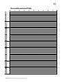
'HFLPDO2+H[DGHFLPDO#7DEOH
3
43
53
63
73
83
93
:3
;3
<3
433
443
453
463
473
483
493
4:3
4;3
4<3
533
543
553
563
573
583
593
5:3
5;3
5<3
633
643
653
663
673
683
693
6:3
6;3
6<3
733
743
753
763
773
783
793
7:3
7;3
7<3
3
3333
333$
3347
334(
335;
3365
336&
3379
3383
338$
3397
339(
33:;
33;5
33;&
33<9
33$3
33$$
33%7
33%(
33&;
33'5
33'&
33(9
33)3
33)$
3437
343(
344;
3455
345&
3469
3473
347$
3487
348(
349;
34:5
34:&
34;9
34<3
34<$
34$7
34$(
34%;
34&5
34&&
34'9
34(3
34($
4
3334
333%
3348
334)
335<
3366
336'
337:
3384
338%
3398
339)
33:<
33;6
33;'
33<:
33$4
33$%
33%8
33%)
33&<
33'6
33''
33(:
33)4
33)%
3438
343)
344<
3456
345'
346:
3474
347%
3488
348)
349<
34:6
34:'
34;:
34<4
34<%
34$8
34$)
34%<
34&6
34&'
34':
34(4
34(%
5
3335
333&
3349
3353
335$
3367
336(
337;
3385
338&
3399
33:3
33:$
33;7
33;(
33<;
33$5
33$&
33%9
33&3
33&$
33'7
33'(
33(;
33)5
33)&
3439
3443
344$
3457
345(
346;
3475
347&
3489
3493
349$
34:7
34:(
34;;
34<5
34<&
34$9
34%3
34%$
34&7
34&(
34';
34(5
34(&
6
3336
333'
334:
3354
335%
3368
336)
337<
3386
338'
339:
33:4
33:%
33;8
33;)
33<<
33$6
33$'
33%:
33&4
33&%
33'8
33')
33(<
33)6
33)'
343:
3444
344%
3458
345)
346<
3476
347'
348:
3494
349%
34:8
34:)
34;<
34<6
34<'
34$:
34%4
34%%
34&8
34&)
34'<
34(6
34('
352),%860'3#&RPPXQLFDWLRQV#,QWHUIDFH#0#+$7968948334
7
3337
333(
334;
3355
335&
3369
3373
337$
3387
338(
339;
33:5
33:&
33;9
33<3
33<$
33$7
33$(
33%;
33&5
33&&
33'9
33(3
33($
33)7
33)(
343;
3445
344&
3459
3463
346$
3477
347(
348;
3495
349&
34:9
34;3
34;$
34<7
34<(
34$;
34%5
34%&
34&9
34'3
34'$
34(7
34((
8
3338
333)
334<
3356
335'
336:
3374
337%
3388
338)
339<
33:6
33:'
33;:
33<4
33<%
33$8
33$)
33%<
33&6
33&'
33':
33(4
33(%
33)8
33))
343<
3446
344'
345:
3464
346%
3478
347)
348<
3496
349'
34::
34;4
34;%
34<8
34<)
34$<
34%6
34%'
34&:
34'4
34'%
34(8
34()
9
3339
3343
334$
3357
335(
336;
3375
337&
3389
3393
339$
33:7
33:(
33;;
33<5
33<&
33$9
33%3
33%$
33&7
33&(
33';
33(5
33(&
33)9
3433
343$
3447
344(
345;
3465
346&
3479
3483
348$
3497
349(
34:;
34;5
34;&
34<9
34$3
34$$
34%7
34%(
34&;
34'5
34'&
34(9
34)3
:
333:
3344
334%
3358
335)
336<
3376
337'
338:
3394
339%
33:8
33:)
33;<
33<6
33<'
33$:
33%4
33%%
33&8
33&)
33'<
33(6
33('
33):
3434
343%
3448
344)
345<
3466
346'
347:
3484
348%
3498
349)
34:<
34;6
34;'
34<:
34$4
34$%
34%8
34%)
34&<
34'6
34''
34(:
34)4
;
333;
3345
334&
3359
3363
336$
3377
337(
338;
3395
339&
33:9
33;3
33;$
33<7
33<(
33$;
33%5
33%&
33&9
33'3
33'$
33(7
33((
33);
3435
343&
3449
3453
345$
3467
346(
347;
3485
348&
3499
34:3
34:$
34;7
34;(
34<;
34$5
34$&
34%9
34&3
34&$
34'7
34'(
34(;
34)5
<
333<
3346
334'
335:
3364
336%
3378
337)
338<
3396
339'
33::
33;4
33;%
33<8
33<)
33$<
33%6
33%'
33&:
33'4
33'%
33(8
33()
33)<
3436
343'
344:
3454
345%
3468
346)
347<
3486
348'
349:
34:4
34:%
34;8
34;)
34<<
34$6
34$'
34%:
34&4
34&%
34'8
34')
34(<
34)6
57
'HFLPDO2+H[DGHFLPDO#7DEOH
833
843
853
863
873
883
893
8:3
8;3
8<3
933
943
953
963
973
983
993
9:3
9;3
9<3
:33
:43
:53
:63
:73
:83
:93
::3
:;3
:<3
;33
;43
;53
;63
;73
;83
;93
;:3
;;3
;<3
<33
<43
<53
<63
<73
<83
<93
<:3
<;3
<<3
3
34)7
34)(
353;
3545
354&
3559
3563
356$
3577
357(
358;
3595
359&
35:9
35;3
35;$
35<7
35<(
35$;
35%5
35%&
35&9
35'3
35'$
35(7
35((
35);
3635
363&
3649
3653
365$
3667
366(
367;
3685
368&
3699
36:3
36:$
36;7
36;(
36<;
36$5
36$&
36%9
36&3
36&$
36'7
36'(
4
34)8
34))
353<
3546
354'
355:
3564
356%
3578
357)
358<
3596
359'
35::
35;4
35;%
35<8
35<)
35$<
35%6
35%'
35&:
35'4
35'%
35(8
35()
35)<
3636
363'
364:
3654
365%
3668
366)
367<
3686
368'
369:
36:4
36:%
36;8
36;)
36<<
36$6
36$'
36%:
36&4
36&%
36'8
36')
5
34)9
3533
353$
3547
354(
355;
3565
356&
3579
3583
358$
3597
359(
35:;
35;5
35;&
35<9
35$3
35$$
35%7
35%(
35&;
35'5
35'&
35(9
35)3
35)$
3637
363(
364;
3655
365&
3669
3673
367$
3687
368(
369;
36:5
36:&
36;9
36<3
36<$
36$7
36$(
36%;
36&5
36&&
36'9
36(3
6
34):
3534
353%
3548
354)
355<
3566
356'
357:
3584
358%
3598
359)
35:<
35;6
35;'
35<:
35$4
35$%
35%8
35%)
35&<
35'6
35''
35(:
35)4
35)%
3638
363)
364<
3656
365'
366:
3674
367%
3688
368)
369<
36:6
36:'
36;:
36<4
36<%
36$8
36$)
36%<
36&6
36&'
36':
36(4
7
34);
3535
353&
3549
3553
355$
3567
356(
357;
3585
358&
3599
35:3
35:$
35;7
35;(
35<;
35$5
35$&
35%9
35&3
35&$
35'7
35'(
35(;
35)5
35)&
3639
3643
364$
3657
365(
366;
3675
367&
3689
3693
369$
36:7
36:(
36;;
36<5
36<&
36$9
36%3
36%$
36&7
36&(
36';
36(5
8
34)<
3536
353'
354:
3554
355%
3568
356)
357<
3586
358'
359:
35:4
35:%
35;8
35;)
35<<
35$6
35$'
35%:
35&4
35&%
35'8
35')
35(<
35)6
35)'
363:
3644
364%
3658
365)
366<
3676
367'
368:
3694
369%
36:8
36:)
36;<
36<6
36<'
36$:
36%4
36%%
36&8
36&)
36'<
36(6
9
34)$
3537
353(
354;
3555
355&
3569
3573
357$
3587
358(
359;
35:5
35:&
35;9
35<3
35<$
35$7
35$(
35%;
35&5
35&&
35'9
35(3
35($
35)7
35)(
363;
3645
364&
3659
3663
366$
3677
367(
368;
3695
369&
36:9
36;3
36;$
36<7
36<(
36$;
36%5
36%&
36&9
36'3
36'$
36(7
:
34)%
3538
353)
354<
3556
355'
356:
3574
357%
3588
358)
359<
35:6
35:'
35;:
35<4
35<%
35$8
35$)
35%<
35&6
35&'
35':
35(4
35(%
35)8
35))
363<
3646
364'
365:
3664
366%
3678
367)
368<
3696
369'
36::
36;4
36;%
36<8
36<)
36$<
36%6
36%'
36&:
36'4
36'%
36(8
;
34)&
3539
3543
354$
3557
355(
356;
3575
357&
3589
3593
359$
35:7
35:(
35;;
35<5
35<&
35$9
35%3
35%$
35&7
35&(
35';
35(5
35(&
35)9
3633
363$
3647
364(
365;
3665
366&
3679
3683
368$
3697
369(
36:;
36;5
36;&
36<9
36$3
36$$
36%7
36%(
36&;
36'5
36'&
36(9
<
34)'
353:
3544
354%
3558
355)
356<
3576
357'
358:
3594
359%
35:8
35:)
35;<
35<6
35<'
35$:
35%4
35%%
35&8
35&)
35'<
35(6
35('
35):
3634
363%
3648
364)
365<
3666
366'
367:
3684
368%
3698
369)
36:<
36;6
36;'
36<:
36$4
36$%
36%8
36%)
36&<
36'6
36''
36(:
352),%860'3#&RPPXQLFDWLRQV#,QWHUIDFH#0#+$7968948334