1
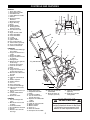
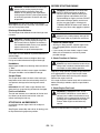
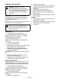
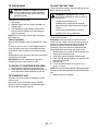
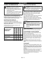
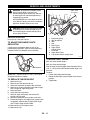
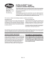
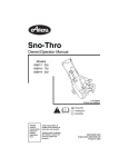
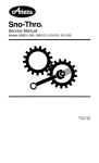
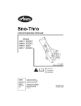
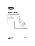
Sno-Thro
®
Owner/Operator Manual
Models
938015 - 322
938016 - 522
ENGLISH
FRANÇAIS
ESPAÑOL
03810900B 5/00
Supersedes 03810900,A
Printed in USA
CONTROLS AND FEATURES
ENGLISH
1. Auger Clutch Bail
2. Recoil Starter Handle
3. Handlebar Knob
4. Chute Deflector Handle
5. Exhaust
6. Discharge Chute
Deflector
7. Discharge Chute
8. Auger Housing
9. Auger
10. Scraper Blade
11. Discharge Chute
Rotation Handle
12. Fuel Tank and Cap
13. Cowl
14. Auger Control Cable
15. Upper Handlebar
16. Lower Handlebar
17. J - Bolt
18. Primer Bulb
19. Ignition Switch
20. Fuel Level Indicator
21. Starter Button (optional)
22. Power Cord (optional)
23. Choke Control Knob
FRANÇAIS
1. Commande d'embrayage
de la turbine
2. Poignée du démarreur à
cordon
3. Bouton du guidon
4. Poignée du déflecteur de
la goulotte
5. Échappement
6. Déflecteur de la goulotte
de décharge
7. Goulotte d'évacuation
8. Carter de la turbine
9. Rotor
10. Lame racleuse
11. Poignée de rotation de la
goulotte d'évacuation
12. Réservoir de carburant et
bouchon
13. Garant
14. Câble de commande du
rotor
15. Guidon supérieur
16. Guidon inférieur
17. Vis en J
18. Poire d'amorçage
19. Commande d'allumage
20. Indicateur de niveau de
carburant
21. Bouton du démarreur (en
option)
22. Cordon d'alimentation
(en option)
23. Bouton du starter
ESPAÑOL
1. Asa del embrague del
sinfín
2. Manilla de retroceso del
arranque
3. Perilla del manillar
4. Asa del deflector de la tolva
5. Escape
6. Deflector de la tolva de
descarga
19
18
22
1
23
15
21
20
OS0241
16
3
2
14
4
5
17
12
6
7
11
8
13
9
10
7. Tolva de descarga
8. Alojamiento del sinfín
9. Sinfín
10. Cuchilla raspadora
11. Asa de rotación de la
tolva de descarga
12. Depósito del combustible
y tapón
13. Cubierta
14. Cable de control del sinfín
15. Manillar superior
16. Manillar inferior
17. Perno en J
18. Botón del cebador
19. Interruptor de encendido
OS1500
20. Indicador del nivel de
combustible
21. Botón del motor de
arranque (opcional)
22. Cable de alimentación
(opcional)
23. Perilla de control del
estrangulador
WARNING
The engine exhaust from this product
contains chemicals known to the State
of California to cause cancer, birth
defects or other reproductive harm.
2
TABLE OF CONTENTS
Service and Adjustments . . . . . . . . . . . . . . . .
Storage . . . . . . . . . . . . . . . . . . . . . . . . . . . . . . .
Troubleshooting . . . . . . . . . . . . . . . . . . . . . . . .
Specifications . . . . . . . . . . . . . . . . . . . . . . . . . .
Accessories and Service Parts . . . . . . . . . . . .
Warranty . . . . . . . . . . . . . . . . . . . . . . . . . . . . . .
14
16
16
17
17
18
INTRODUCTION
THE MANUAL
PRODUCT REGISTRATION
Before operation of unit, carefully and completely read
your manuals. The contents will provide you with an
understanding of safety instructions and controls
during normal operation and maintenance.
All reference to left, right, front, or rear are given from
operator standing in operation position and facing the
direction of forward travel.
A warranty registration card must be filled out, signed,
and returned at time of purchase. This card activates
the warranty. Claims meeting requirements during
limited warranty period will be honored.
MODEL AND SERIAL NUMBERS
Transfer
model & serial
number label
from product
registration
here.
When ordering replacement parts
or making service inquiries, know
the Model and Serial numbers of
your unit and engine.
Numbers are located on the product
registration form in the unit literature
package. They are printed on a
serial number label, located on the
frame of your unit.
Serial
Number
Label
UNAUTHORIZED REPLACEMENT PARTS
Use only Ariens replacement parts. The replacement of
any part on this vehicle with anything other than an
Ariens authorized replacement part may adversely
affect the performance, durability, or safety of this unit
and may void the warranty. Ariens disclaims liability for
any claims or damages, whether warranty, property
damage, personal injury or death arising out of the use
of unauthorized replacement parts.
DISCLAIMER
Ariens reserves the right to discontinue, make changes
to, and add improvements upon its products at any time
without public notice or obligation.The descriptions and
specifications contained in this manual were in effect at
printing. Equipment described within this manual may
be optional. Some illustrations may not be applicable to
your unit.
OS0192
• Record Unit Model and Serial numbers here.
• Record Engine Model and Serial numbers here.
GB - 3
ENGLISH
Controls and Features . . . . . . . . . . . . . . . . . . . . 2
Introduction . . . . . . . . . . . . . . . . . . . . . . . . . . . . 3
Safety. . . . . . . . . . . . . . . . . . . . . . . . . . . . . . . . . . 4
Assembly . . . . . . . . . . . . . . . . . . . . . . . . . . . . . . 8
Operation . . . . . . . . . . . . . . . . . . . . . . . . . . . . . . 9
Maintenance . . . . . . . . . . . . . . . . . . . . . . . . . . . 13
DELIVERY
Customer Note: If you have purchased this product
without complete assembly and instruction by your
retailer, it is your responsibility to:
• Read and understand all assembly instructions in
this manual.
WARNING: Improper assembly or
adjustments can cause serious injury.
If you do not understand or have difficulty following the
instructions, contact your nearest Ariens Dealer for
assistance. To locate your nearest Ariens Dealer, call
1-800-678-5443 or visit our web site at
http://www.ariens.com.
• Do not operate the Sno-Thro unless all controls
function as described in this manual.
Before attempting to operate your Sno-Thro:
1. Make sure all assembly has been properly
completed.
2. Understand all Safety Precautions provided in the
manuals.
3. Review control functions and operation of the unit.
4. Review recommended lubrication, maintenance
and adjustments.
5. Review Limited Warranty Policy.
6. Fill out Original Purchaser Registration Card and
return the card to Ariens Company.
SAFETY
SAFETY ALERTS
PRACTICES AND LAWS
Look for these symbols to point out
important safety precautions. They mean:
Attention! Personal Safety Is
Involved!
Become Alert! Obey The Message!
Practice usual and customary safe working
precautions, for the benefit of yourself and others.
Understand and follow all safety messages. Be alert to
unsafe conditions and the possibility of minor,
moderate, or serious injury or death. Learn applicable
rules and laws in your area.
REQUIRED OPERATOR TRAINING
The safety alert symbol is used in decals on the unit
and with proper operation procedures in this manual.
Understand the safety message. It contains important
information about personal safety on or near the unit.
Original purchaser of this unit was instructed by the
seller on safe and proper operation. If unit is to be used
by someone other than original purchaser; loaned,
rented or sold, ALWAYS provide this manual and any
needed safety training before operation.
DANGER: IMMINENTLY HAZARDOUS
SITUATION! If not avoided, WILL RESULT in
death or serious injury.
WARNING: POTENTIALLY HAZARDOUS
SITUATION! If not avoided, COULD RESULT
in death or serious injury.
CAUTION: POTENTIALLY HAZARDOUS
SITUATION! If not avoided, MAY RESULT in
minor or moderate injury. It may also be used
to alert against unsafe practices.
NOTATIONS
NOTE: General reference information for proper operation and maintenance practices.
IMPORTANT: Specific procedures or information
required to prevent damage to unit or attachment.
GB - 4
SAFETY DECALS AND LOCATIONS
ALWAYS replace missing or damaged Safety Decals.
Refer to figure below for Safety Decal locations.
2
3
1
4
OS1681
1 & 2. DANGER
Keep clear of auger while engine is
running.
• Keep all controls, guards and safety devices
properly serviced and functional.
OL1070
• Never direct discharge towards persons or
property that may be injured or damaged by
thrown objects.
SAFETY
Read operator’s manual.
3.
DANGER! ROTATING PARTS! Stop
engine and remove ignition key before
clearing.
OL1801
• Allow operation only by properly trained adult,
never children.
OL0900
4.
Stop engine and remove ignition key
prior to leaving operator’s position for
any reason.
OL4010
GB - 5
IMPORTANT ENGINE INFORMATION
CAUTION: For personal protection refer to
owner’s manual for important safety and
maintenance information.
SAFETY RULES
ALWAYS allow unit and engine to adjust to outdoor
temperatures before clearing snow.
ALWAYS disengage attachment drive, stop unit and
engine, remove key, allow moving parts to stop before
leaving operator’s position for any reason.
Walk Around Inspection
Complete a walk around inspection of unit and work
area to understand:
• Work area.
• Your unit.
• All safety decals.
Work Area
ALWAYS check overhead and side clearances carefully
before operation. ALWAYS be aware of traffic when
operating along streets or curbs.
Keep children and people away. Keep children out of
work area and under watchful care of a responsible
adult.
DO NOT allow adults to operate unit without proper
training.
Keep area of operation clear of all toys, pets, and
debris. Thrown objects can cause injury.
Check for weak spots on dock, ramps or floors. Avoid
uneven work areas and rough terrain. Stay alert for
hidden hazards.
Always be sure of your footing, especially when
operating in reverse. Walk, never run during operation.
Falling snow, fog, etc. can reduce vision and cause an
accident. Operate unit only when there is good visibility
and light.
Unit
ALWAYS keep protective structures, guards, and
panels in good repair, in place and securely fastened.
NEVER modify or remove safety devices.
Check clutch and brake operation frequently. Adjust
and service as required. Auger must stop quickly when
control bail is released.
Use only approved extension cords and receptacles
when starting units equipped with Electric starter. DO
NOT connect electric starter cord to any wiring system
that is not a three wire grounded system.
Operation
Understand:
• How to operate all controls
• The functions of all controls
• How to STOP in an Emergency
Before starting engine, disengage control(s).DO NOT
operate at too fast a rate.
DO NOT change engine governor settings or
over-speed engine.
Slow down and turn corners slowly.
Disengage attachment drive when traveling from one
work area to another.
Run unit a few minutes after clearing snow to prevent
freeze-up of attachment.
Disengage attachment when not in use.
Do not operate in reverse unless absolutely necessary.
ALWAYS back up slowly. Always look down and
behind before and while backing.
Never leave a running unit unattended. ALWAYS shut
off engine before leaving unit. ALWAYS remove key to
prevent unauthorized use.
Never carry passengers.
Avoid uneven and rough terrain. DO NOT operate near
drop offs, ditches, or embankments. Unit can suddenly
turn over if a wheel is over the edge of a cliff or ditch, or
if an edge caves in.
Abnormal Vibrations are a warning of trouble. Striking a
foreign object can damage unit. Immediately stop unit
and engine. Remove key and wait for all moving parts
to stop. Remove wire from spark plug. Inspect unit and
make any necessary repairs before restart.
Hazardous Slopes
DO NOT operate on steep slopes. DO NOT clear snow
across the face of slopes. Keep all movement on
slopes slow and gradual. DO NOT make sudden
changes in speed or direction.
DO NOT park unit on a slope unless absolutely
necessary. When parking on a slope always block the
wheels.
Child Safety
NEVER allow children to operate or play on or near
unit. Be alert and shut off unit if children enter area.
Personal Safety
Only trained adults may operate unit.
Training includes actual operation.
NEVER operate unit after or during the use of
medication, drugs or alcohol. Safe operation requires
your complete and unimpaired attention at all times.
NEVER allow anyone to operate this unit when their
alertness or coordination is impaired.
DO NOT operate unit without wearing adequate winter
outer garments. Wear adequate safety gear and
protective gloves. Wear proper footwear to improve
footing on slippery surfaces.
Protect eyes, face and head from objects that may be
thrown from unit. Wear appropriate hearing protection.
Avoid sharp edges. Sharp edges can cut. Moving parts
can cut off fingers or a hand.
GB - 6
ALWAYS keep hands and feet away from all rotating
parts during operation. Rotating parts can cut off body
parts.
ALWAYS keep hands away from all pinch points.
DO NOT touch unit parts which might be hot from
operation. Allow parts to cool before attempting to
maintain, adjust or service.
NEVER place your hands or any part of your body or
clothing inside or near any moving part while unit is
running.
DO NOT wear loose clothing or jewelry and tie back
hair that may get caught in rotating parts.
Keep children and people away from unit during
operation.
Never direct discharge towards persons or property
that may be injured or damaged by thrown objects. Use
extreme caution on gravel surfaces. Stay alert for
hidden hazards or traffic.
Deflected materials can cause injury and property
damage.
Always stand clear of the discharge area when
operating this unit.
Fumes from engine exhaust can cause injury or death.
DO NOT run engine in an enclosed area. Always
provide good ventilation.
Storage
For unit storage or extended storage:
• NEVER store with fuel in fuel tank, inside a
building where any ignition sources are present.
• Allow engine to cool completely.
•
For extended storage, clean unit thoroughly. See
Engine Manual for proper storage.
Transport
Use extra care when loading or unloading unit onto
trailer or truck.
Secure unit chassis to transport vehicle. NEVER
secure from rods or linkages that could be damaged.
DO NOT transport machine while engine is running.
Spark Arrester
This product is equipped with an internal combustion
type engine. DO NOT use unit on or near any
unimproved, forest-covered or brush covered land
unless exhaust system is equipped with a spark
arrester meeting applicable local, state or federal laws.
A spark arrester, if it is used, must be maintained in
effective working order by operator.
Service
Before cleaning, removing clogs or making any
inspections, repairs, etc.: disengage clutch(es), stop
unit and engine, remove key, allow moving parts to
stop. Allow hot parts to cool.
Before tipping unit up onto housing, remove enough
fuel so no spills will occur. Ensure unit is secure and
will not tip over during maintenance.
Fuel is highly flammable and its vapors are explosive.
Handle with care. Use an approved fuel container.
NO smoking, NO sparks, NO flames. ALWAYS allow
engine to cool before servicing.
NEVER fill fuel tank when engine is running or hot from
operation.
NEVER fill or drain fuel tank indoors.
Replace fuel cap securely and clean up spilled fuel.
ALWAYS maintain unit in safe operating condition.
Damaged or worn out muffler can cause fire or
explosion.
Keep all hardware properly tightened.
Cleaning
Keep unit free of ice or other debris. Clean up oil or fuel
spills.
GB - 7
ASSEMBLY
TOOLS REQUIRED
• 7/16" Open-end wrench
6
TO REMOVE UNIT FROM CARTON
1.
2.
3.
4.
1
Cut off top of carton.
Remove front and rear inserts and literature pack.
Cut out back of carton and roll unit out.
Remove protective packaging materials.
4
2
3
ASSEMBLY
Handlebar Assembly
5
1.
2.
3.
4.
Ha
r
Lit dwa
era re
/
Pa ture
ck
Lower Handle Bar
Upper Handle Bar
J-Bolt
Knob
7
5. J-Bolt Holes
6. Auger Clutch Bail
7. Retaining Nuts
OS1530
Discharge Chute Assembly
4
2
1
OS1510
1. Remove retaining nuts and handlebar knobs and
release J-bolts from lower handlebar.
2. Unfold upper handlebar.
NOTE: Adjust handlebar to a height comfortable for the
operator. Refer to Handlebars in Operation.
3. Put J-bolts through the upper handlebar and lower
handlebar holes.
4. Replace retaining nuts and tighten handlebar
knobs to secure upper handlebar.
1. Discharge Chute
2. Rear Screw and
Nut
3
3. Side Hardware
4. Chute Handle
OS1520
1. Remove screw and nut from rear of discharge
chute.
2. Tip discharge chute up and install hardware just
removed. Tighten hardware at rear of discharge
chute first, then sides.
CHECKLIST
Please complete the following checklist before
proceeding:
❑ All assembly instructions have been completed.
❑ No remaining loose parts in carton.
❑ Handlebar is adjusted comfortably and tightened
securely.
While learning how to use your unit, pay extra
attention to the following important items:
❑
❑
❑
GB - 8
Fill fuel tank with proper gasoline/oil mix.
Become familiar with all controls – their location
and function.
Be certain that all hardware is properly tightened.
OPERATION
CONTROLS AND FEATURES
Auger Clutch Bail
Squeeze the auger clutch bail
against the handlebar to engage
auger.
Refer to Figure 1 on the inside front cover for controls
and features locations.
Ignition Switch
The ignition switch is operated with a removable key
that has two positions.
Engaged
WARNING: ACCIDENTAL ENGINE START
UP or UNAUTHORIZED USE could result in
death or serious injury. ALWAYS shut off unit
and remove key before servicing or leaving
unit unattended.
STOP
RUN
"STOP" Position: Ignition system is shut
down.
"RUN" Position: All controls are
operable.
OS1680
Release bail to disengage and
brake auger.
Disengaged
OS1560
IMPORTANT: Check auger to be sure it is not frozen. If
belt squeals when clutch bail is engaged, auger is
frozen. Immediately release the clutch bail and move
the unit to a heated area to thaw.
IMPORTANT: Check clutch/brake function before each
use. If auger clutch bail moves freely with no resistance
before contacting handlebar, adjust or repair unit
before operating.
Primer Bulb
To start the engine, the key must be in the "RUN"
position.
To stop the engine, turn the key to the "STOP" position.
Push in the primer Bulb to add fuel for
easier engine start. See Starting and
Shut Off.
Auger
OS1620
WARNING: THROWN OBJECTS could cause
personal injury and/or property damage.
ALWAYS discharge in a safe direction.
Disengage auger when unit is traveling to
work area or is not in use. Use extreme
caution when operating on or crossing gravel
surfaces.
Choke Control Knob
OS1570
When pulled out (away from auger
housing) the choke control knob chokes
off air to the engine for easier start.
When pushed in, control knob allows for
normal operation.
IMPORTANT: When engine has started, open choke
CAUTION: STRIKING FOREIGN OBJECTS
may damage unit and result in minor or
moderate injury. Shut off unit and engine.
Check for any damage or loose parts and
repair before restart.
slowly by gradually pushing choke control in.
Recoil Starter Handle
When handlebar is lifted so auger contacts the ground,
auger propels unit forward while collecting snow.
Forward speed will vary according to depth and
moisture content.
When pulled, handle will crank engine.
IMPORTANT: DO NOT let handle snap back against
unit.
Discharge Chute
The discharge chute directs the flow of snow away from
the area being cleared. The discharge chute rotates
220°. Rotate chute with the discharge chute handle.
WARNING: IMPROPER ADJUSTMENT
could result in death or serious injury. AUGER
BRAKE MUST DISENGAGE when clutch is
engaged. BRAKE MUST STOP AUGER
WITHIN 5 SECONDS of releasing auger
clutch bail.
GB - 9
DANGER: ROTATING PARTS will cause
serious injury or death. NEVER reach into
discharge chute or housing while engine is
running.
WARNING: THROWN OBJECTS can result in
personal injury and/or property damage.
ALWAYS position discharge chute and
deflector in safe direction and angle before
starting engine. DO NOT allow anyone in front
of unit during operation. Be familiar with area
of operation.
BEFORE STARTING ENGINE
WARNING: IMPROPER CLOTHING AND
SAFETY GEAR could result in death or
serious injury. Wear adequate winter gear,
protective gloves and footwear which will
improve footing on slippery surfaces. DO NOT
wear loose clothing or jewelry and tie back
hair that may get caught in rotating parts.
THROWN OBJECTS could result in death or
serious injury. Wear safety goggles to protect
eyes.
IMPORTANT: DO NOT force frozen chute controls.
Start engine and run for 3-5 minutes. If still frozen, take
unit to a warm place to thaw.
Discharge Chute Deflector
The discharge chute deflector controls how high snow
is thrown.
CAUTION: THROWN OBJECTS can cause
personal injury and/or property damage. DO
NOT throw snow any higher than necessary
If chute deflector does not stay in set position,
adjust as directed in Service and
Adjustments, or repair before operation.
Use handle at rear of deflector to position deflector at
desired height.
Push down handle to increase height of discharge.
Pull up on handle to decrease height of discharge.
CAUTION: THROWN OBJECTS can result in
personal injury and/or property damage. DO
NOT throw snow any higher than necessary.
1. Check for Frozen Auger
• With key in "Stop" position, squeeze auger clutch
bail to Engaged position and pull recoil starter
handle.
• If you cannot pull starter handle, auger is frozen.
Move unit to a heated area to thaw to prevent
possible damage.
2. Check Function of Clutches
WARNING: FAILURE OF CLUTCHES OR
BRAKES may result in death or serious injury.
Check clutch and brake function before each
use. Repair or adjust before operation.
Handlebars
Adjust upper handlebar by selecting alternate holes for
"J" Bolts.
Tighten handlebar knobs to secure upper handlebar.
The upper handlebar can be folded for storage.
Scraper Blade
The scraper blade allows the back of the housing to
keep better contact with the surface being cleared. It
also prevents damage to the housing from normal
wear.
IMPORTANT: DO NOT allow scraper blade to wear
down too far or auger housing will become damaged.
With key in "Stop" position, squeeze auger clutch bail
to Engaged position and pull recoil starter handle.
Auger should rotate with the turning of the engine.
Release the auger clutch bail.
If the auger clutch bail moves freely with no resistance
before contacting handlebar, adjust or repair before
operation.
3. Check Engine Fuel Level
WARNING: FLAMMABLE FUEL and its
EXPLOSIVE VAPORS can cause death or
serious injury. handle fuel with extreme care.
ALWAYS use an approved fuel container. NO
Smoking! NO Lighted Materials! NO Open
Flames! Allow engine to cool before any
service.
Fuel Level Indicator
The fuel level indicator is an extension of the fuel tank
that allows you to see the level of fuel in the tank
without removing the fuel cap.
STOPPING IN AN EMERGENCY
Immediately release auger clutch bail to stop unit
movement.
Stop Engine, remove Key and wait for all rotating parts
to stop before leaving operators position.
Add fuel if required. Refer to Filling the Fuel Tank.
GB - 10
STARTING AND SHUTOFF
WARNING: FAILURE TO FOLLOW
INSTRUCTIONS could result in personal
injury and/or damage to unit. DO NOT attempt
to start your unit at this time. Read entire
Owner/Operator Manual and the Engine
Manual first.
IMPORTANT: At start up, allow unit and engine to
adjust to the outdoor temperatures before clearing
snow. Before shut off, run auger a few minutes to
prevent freeze-up of auger.
NOTE: Try out each control without the engine running
to see how they work and what they do.
5. Turn key to "Run" position.
6. Connect Female End of power cord to switch Box.
7. Plug Male End of power cord into 120 Volt AC
receptacle.
8. Push starter button to crank engine.
9. When engine starts, release starter button
10. Open choke slowly by gradually pushing choke
control knob in.
11. Disconnect power cord from receptacle first, then
from switch box.
Shutoff
1. Engage and run auger a few minutes after use to
prevent freeze-up of auger.
2. Release auger clutch bail and allow auger to stop.
3. Turn ignition switch to "Stop" position.
4. Remove key.
WARNING: THROWN OBJECTS could cause
death or serious injury. ALWAYS position
discharge chute straight ahead (away from
operator) for starting.
Manual Start
1. Turn discharge chute straight ahead.
2. Push primer Bulb 1 to 3 times for cold engine.
NOTE: When temperature is below -15° F (-26° C)
additional priming may be needed.
3. Pull choke control knob out.
NOTE: A warm engine requires less choking than a
cold engine.
4. Insert key into ignition switch.
5. Turn key to "Run" position.
6. Stand to right of unit. Grasp starter handle and pull
rope out slowly until it pulls harder, this is
compression stroke, let rope rewind slowly.
7. Pull rope with a rapid continuous full arm stroke.
Let rope rewind slowly.
IMPORTANT: DO NOT let starter handle snap against
unit.
8. Repeat until engine starts. (If engine does not
start, refer to Troubleshooting.)
9. When engine has started, open choke slowly by
gradually pushing choke control knob in.
Electric Start (optional)
IMPORTANT: DO NOT crank engine for more that 20
seconds. ALWAYS allow starter to cool down for 10
minutes between each try or starter will be damaged.
1. Turn discharge chute straight ahead.
2. Push primer Bulb 1 to 3 times for cold engine.
NOTE: When temperature is below -15° F (-26° C)
additional priming may be needed.
3. Pull choke control knob out.
NOTE: A warm engine requires less choking than a
cold engine.
4. Insert key into ignition switch.
GB - 11
FILLING THE FUEL TANK
TO THROW SNOW
CAUTION: HIDDEN HAZARDS may result in
minor or moderate injury and/or damage to
unit. Stay alert for holes, rocks, roots, traffic,
and other hazards.
To propel unit and throw snow:
1. Start engine.
2. Squeeze auger clutch bail against handlebar to
engage auger.
3. Lift handlebar so auger contacts surface to be
cleared. Lift the handlebar only high enough to
propel unit forward.
NOTE: Do not lift so high to allow snow to kick back
from under unit.
Tips for Operation
Snow is best removed as soon as possible after a snow
fall.
To clear an area, run unit in an overlapping series of
paths. For large areas; start in the middle and throw
snow to each side, so snow is not cleared more than
once.
ALWAYS direct snow away from area to be cleared and
with direction of the wind.
IMPORTANT: DO NOT overload unit capacity by
attempting to clear snow at too fast a rate.
TO TRAVEL TO ANOTHER WORK AREA
1. Release auger clutch bail to disengage auger.
2. Press down on handlebar enough to raise front of
unit slightly off the ground and push or pull unit.
TO TRANSPORT UNIT
Check fuel level by looking at fuel level indicator on rear
of unit. Add fuel as required.
WARNING: FLAMMABLE FUEL and its
EXPLOSIVE VAPORS can result in death or
serious injury.
Handle fuel with extreme care.
ALWAYS use an approved fuel container.
No Smoking! No Lighted Materials! No Open
Flames!
Allow engine to cool before any service.
ALWAYS clean up any spilled fuel.
To add fuel to fuel tank:
IMPORTANT: Two cycle engines require that oil be
mixed with fuel. Failure to mix oil with fuel will result in
seizure and severe damage to engine. DO NOT use
gasohol or gasoline containing alcohol because
alcohol will cause internal parts to deteriorate. See
Engine Manual for correct type and grade of fuel.
1. ALWAYS place unit in open or well ventilated area.
2. Stop engine and allow to cool.
3. See engine manual for proper fuel/oil mixture.
4. Clean fuel cap and surrounding area to prevent dirt
from entering fuel tank.
5. Remove cap.
6. Fill fuel tank with mixture. Tank capacity is 1.2
quarts (1.1 liters).
NOTE: Fuel mixture left standing for prolonged periods
will begin to separate; thoroughly shake mixture before
use.
7. Replace fuel cap and tighten.
Use extra care when loading or unloading unit onto
trailer or truck.
Secure unit chassis to transport vehicle. NEVER
secure by rods or linkages that could be damaged.
Always shutoff engine for transport.
GB - 12
MAINTENANCE
CHECK CLUTCH FUNCTION
GENERAL RECOMMENDATIONS
WARNING: ACCIDENTAL ENGINE START
UP can cause death or serious injury.
ALWAYS stop engine, remove key, and wait
for moving parts to stop, before performing
maintenance or service.
HOT SURFACES can cause death or serious
injury. DO NOT touch parts which are hot from
operation. ALWAYS allow parts to cool.
Some adjustments must be made periodically to
properly maintain your unit. All adjustments in the
SERVICE AND ADJUSTMENTS section of this manual
should be checked at least once each season.
MAINTENANCE SCHEDULE
WARNING: FAILURE OF CLUTCHES OR
BRAKES may result in death or serious injury.
Check clutch and brake function before each
use. Repair or adjust before operation.
With key in "STOP" position, squeeze auger clutch bail
to Engaged position and pull recoil starter handle.
Auger should rotate with the turning of the engine.
Release the auger clutch bail.
If the auger clutch bail moves freely with no resistance
before contacting handlebar, adjust or repair.
NOTE: The unit will require control cable and/or idler
adjustment after 20 hours of operation on a new unit or
new drive belt. See Service and Adjustments for
instructions.
Check Clutch Function
Every Season
•
•
Check Fasteners
Clean Engine Cooling
System
Clean Unit
Every 10 Hours
After Each Use
MAINTENANCE
SCHEDULE
Before Each Use
The chart below shows the recommended
maintenance schedule that should be performed on a
regular basis. More frequent service may be required
due to heavy loads or use.
See Engine Manual for further maintenance and
troubleshooting information.
•
•
WARNING: IMPROPER ADJUSTMENT
could result in death or serious injury. AUGER
BRAKE MUST DISENGAGE when clutch is
engaged. BRAKE MUST STOP AUGER
WITHIN 5 SECONDS of releasing auger
clutch bail.
CHECK FASTENERS
Keep all nuts, bolts, and screws properly tightened.
CLEAN ENGINE COOLING SYSTEM
Engine is air cooled. Air must circulate freely around
engine to prevent overheating.
Every year (more often if conditions require) remove
cooling shrouds and clean cooling fins. Clean external
surfaces of engine of dust, dirt and oil deposits which
can contribute to improper cooling. Refer to Engine
Manual.
IMPORTANT: DO NOT operate engine with cooling
shrouds removed. Engine overheating and damage will
result.
CLEAN UNIT
After each use, brush snow and debris off with a soft
bristled brush. Occasionally apply a light coat of spray
lubricant to exposed metal joints and surfaces. Wipe off
excess with soft cloth. Do not use abrasives or harsh
cleaners.
IMPORTANT: Take steps to prevent rust and corrosion.
Never spray unit with water or store unit outdoors.
Water can seep into sealed bearings, which are sealed
against dirt and debris only, causing reduced
component life.
GB - 13
SERVICE AND ADJUSTMENTS
WARNING: ACCIDENTAL ENGINE START
UP can cause death or serious injury.
ALWAYS stop engine, remove key, and wait
for moving parts to stop before performing
maintenance or service.
HOT SURFACES can cause death or serious
injury. DO NOT touch parts which are hot from
operation. ALWAYS allow parts to cool.
1/32"-1/16"
(1-1.6 cm)
1
2
3
4 6
5
7
5 (3HP)
CAUTION: FUEL SPILLS may result in minor
or moderate injury and/or damage to unit. If
unit must be tipped, remove enough fuel so
that no spills will occur.
9
SERVICE POSITION
8
1.
2.
3.
4.
5.
6.
Extension Spring
Idler Arm/Brake
Idler
Slot
Belt Fingers
Auger Clutch
Control Cable
7. Drive Belt
8. Auger Drive Pulley
9. Cap Screw, Washer, Auger Shaft
Place unit on a flat level surface.
TO ADJUST DISCHARGE CHUTE
DEFLECTOR
If discharge chute deflector does not stay in set
position during operation, adjust chute by tightening
fasteners evenly until deflector stays in position.
OS0053
TO ADJUST BELT FINGER
Fasteners
OS0181
NOTE: Use a T30 Torx Drive or a 3/16” (.19 cm) wide
Straight Screwdriver to tighten.
TO REPLACE THE DRIVE BELT
1.
2.
3.
4.
5.
6.
7.
8.
9.
10.
11.
3HP units have two belt fingers.
5HP units have one belt finger.
With the auger clutch engaged, there should be 1/32 to
1/16" (1-1.6 cm) clearance between the belt finger and
drive belt.
To adjust:
1. Loosen bolt holding the belt finger.
2. Rotate the belt finger around the bolt to the correct
position.
3. Tighten bolt.
Remove fuel cap.
Remove cowl and replace fuel cap.
Disconnect extension spring on idler arm/brake.
Remove cap screw and washer from end of auger
shaft and pull off auger drive pulley.
Remove old belt.
Install new belt onto pulleys
Reinstall auger drive pulley and secure with
washer and cap screw
Reconnect extension spring to idler arm/brake.
Ensure belt finger(s) and auger clutch control cable
are properly adjusted. See To Adjust Belt Finger
and To Adjust Auger Control Cable.
Remove fuel cap and replace cowl.
Replace fuel cap.
GB - 14
TO ADJUST IDLER POSITION
TO ADJUST AUGER CONTROL CABLE
WARNING: IMPROPER ADJUSTMENT
could result in death or serious injury. AUGER
BRAKE MUST DISENGAGE when clutch is
engaged. BRAKE MUST STOP AUGER
WITHIN 5 SECONDS of releasing auger
clutch bail.
There must ALWAYS be some slight noticeable slack in
the auger control cable when the auger is disengaged.
This allows Extension Spring to pull idler Arm/Brake,
which applies the brake to the Belt.
The auger clutch bail should travel 6-3/4 to 7-1/4”
(17.1-18.4 cm) before contacting handlebar.
A properly adjusted clutch must extend control cable
Spring approximately 1/4 to 3/8” (6-10 mm) before
clutch bail contacts handlebar.
1. Shut off engine.
2. Loosen locknut on threaded section of control
cable adjusting feature.
3. Turn solid section to provide some slight,
noticeable slack in cable.
4. Hold the solid section with a pliers and gently, with
a small wrench, tighten the locknut.
IMPORTANT: If there is still no resistance, the idler
position must be adjusted. See To Adjust Idler Position.
1/4- 3/8"
to
1/4
3/8”
(6-10 mm)
The idler must be as close as possible to the drive belt
when the auger clutch is disengaged, but not so close
that it causes auger rotation.
WARNING: ROTATING PARTS can cut off
body parts. Keep hands and feet away. Loose
clothing, long hair or scarves can get caught
in rotating parts and cause death or serious
injury.
To adjust the idler position:
IMPORTANT: If adjustment cannot be achieved, the
Drive Belt must be replaced.
1. Shut off engine, allow to cool, and remove cowl.
2. Ensure control cable has some slight, noticeable
slack when auger clutch is disengaged (bail in
lowered position).
3. Ensure belt fingers are properly adjusted. See To
Adjust Belt Finger.
4. Loosen idler hardware, reposition idler along slot in
idler arm, and tighten hardware.
5. Check for proper extension of control cable spring.
See To Adjust Auger Control Cable.
6. Start engine and ensure auger does not rotate
when auger clutch is disengaged.
7. Shut off engine.
8. Repeat the above steps until proper adjustment is
achieved.
9. Replace cowl.
1/32"-1/16"
(1-1.6 cm)
1
1
2
3 4
5
2
5 (3HP)
4
3
1. Control Cable
Spring
2. Adjusting Feature
5
3. Locknut
4. Threaded Section
5. Solid Section
OS1220
GB - 15
1.
2.
3.
4.
Idler Arm/Brake
Idler
Slot
Auger Clutch
Control Cable
5. Belt Fingers
OS0053
STORAGE
ENGINE
UNIT
WARNING: FLAMMABLE FUEL and its
EXPLOSIVE VAPORS can cause death or
serious injury. DO NOT store unit inside a
building with fuel in the fuel tank where any
ignition sources are present. Drain fuel
outdoors away from any ignition source. Allow
engine to cool before storing in any enclosure.
Only use approved fuel containers.
When storing unit for extended periods of time, remove
all fuel from tank and carburetor (run dry). Refer to
Engine Manual.
Run with auger clutch engaged a few minutes after
each use to free unit of any loose or melting snow.
Inspect unit for visible signs of wear, breakage or
damage. Order any parts required and make
necessary repairs to avoid delays when beginning use
again.
Keep all nuts, bolts and screws properly tightened and
know unit is in safe working condition.
TROUBLESHOOTING
PROBLEM
PROBABLE CAUSE
CORRECTION
Engine will
not crank
1. Ignition switch not in "RUN" position.
2. Bad starter or wire connection.
3. Electrical problem
1. Turn key to "RUN" position.
2. Check connections. See your Dealer.
3. Check wiring for wear, damage or poor
connections. See your Dealer.
Engine will
not start
1.
2.
3.
4.
1.
2.
3.
4.
Engine stops
1. Improperly mixed or contaminated
fuel.
2. No spark.
1. Use only clean, properly mixed fuel. If
necessary, drain tank and refill with new fuel
mixture.
2. Check spark plug and connecting wire.
Discharge
chute will not
turn
1. Chute gears are frozen.
1. Move unit to a warm area to thaw.
Auger will not
turn or throw
snow
1. Auger is frozen in place.
2. Ice or debris is obstructing auger.
3. Auger control cable out of
adjustment
4. Drive belt slipping; idler out of
adjustment.
1. Move unit to a warm area to thaw.
2. With engine off, and auger disengaged,
check for obstructions and remove.
3. Adjust cable. See Service and Adjustments.
4. Adjust idler. See Service and Adjustments.
Ignition switch not in "RUN" position.
Bad starter or wire connection.
Engine ignition problem.
Fuel tank is empty.
GB - 16
Turn key to "RUN" position.
Check connections. See your Dealer.
See Engine Manual.
Fill tank with properly mixed fuel. Prime
engine, set choke for easier start.
SPECIFICATIONS
Model Number
ACCESSORIES
938015
938016
322
522
Engine Power - HP (KW) 2 Cycle
3 (2.24)
5 (3.73)
Engine Operating Fast Idle
Speed - RPM
4300
3600
Engine Displacement - cu.
in. (cc)
6.0 (98)
8.46 (139)
Description
Fuel
Fuel to Oil Mix
Fuel Filter Neck Inside Dia.
- in (cm)
2.8 (7.1)
Optional
22 (56)
Snow Throwing Distance ft (meters)
3-30 (0.9-9.1)
Chute Rotation Angle
6.0 (15.2)
Handlebars Max. Extended
Height - in (cm)
40.8 (104)
Minimum Folded Height - in
(cm)
25.8 (65.5)
Length - in (cm)
43.2 (110)
Minimum Folded Length in (cm)
34.5 (87.6)
Width - in (cm)
73800300
Discharge Chute Crank Kit
73800400
Service Kit (5 HP)
73800500
Service Kit (3 HP)
SERVICE PARTS
Part no.
Qty
Description
07236400
1
Drive Belt (3HP)
07236300
1
Drive Belt (5HP)
22 (56)
58 (26.4)
Auger Dia - in (cm)
Wheel Size - in (cm)
Electric Starter (3 HP) - Canada
220°
Chute Inside Dia - in (cm)
Drive Belt
73700200
Installed
Snow Clearing Width - in
(cm)
Auger Speed - RPM
Electric Starter (3 HP)
Be sure to always use genuine Ariens parts to keep
your unit running like new.
See engine manual.
1.2 (1.1)
Weight - lbs (Kg)
73700100
See Engine Manual for type
and grade
Fuel Tank Capacity - qt
(Liters)
120V Electric Start
See your authorized Ariens Dealer to add these
optional accessories.
75 (38.5)
9.0 (23)
1220
1200
3L Section, Single “V”
Construction, Raw Edge
Kevlar Cord
7.0 x 1.5 (18 x 3.8)
GB - 17
2 Year Limited Warranty
Ariens Company
655 West Ryan Street
P.O. Box 157
Brillion, WI 54110-0157
920-756-2141
Fax 920-756-2407
www.ariens.com
Ariens Company warrants to the original purchaser that consumer products manufactured
by Ariens Company will be free from defects in material and workmanship for a period
of two (2) years after the date of purchase, and will repair any defect in material or
workmanship, and repair or replace any defective part, subject to the conditions, limitations
and exclusions set forth herein.
The two year duration of this warranty applies only if the product is put to ordinary,
reasonable, and usual personal, family, or household uses. If the product is put to any
business, commercial, or industrial use such as, but not limited to, commercial landscaping,
mowing or snow removal services, or golf course or park maintenance, or agricultural
or farmstead use, then the duration of this warranty is ninety (90) days after the date
of purchase, or one (1) year after the date of purchase if the product is labeled as a
Professional/Commercial Product. If any product is rented or leased, then the duration
of this warranty is ninety (90) days after the date of purchase.
Genuine Ariens service parts and accessories not purchased with the product covered
by this warranty, but which are later purchased and used with that product, are warranted
to be free from defects in material and workmanship for a period of ninety (90) days
after date of purchase, and Ariens Company will repair or replace any such part or
accessory free of charge, except for labor, during that period.
This warranty is subject to the following conditions, limitations, and exclusions:
This warranty is valid only if the following conditions are
met:
• The warranty registration card must be completed and
returned to Ariens Company.
• The purchaser must perform maintenance and minor
adjustments explained in the owner’s manual.
• The purchaser must promptly notify Ariens Company or an
authorized Ariens service representative of the need for
warranty service.
This warranty is subject to the following limitations:
• The purchaser must transport the product to and from the
place of warranty service.
• Warranty service must be performed by an authorized Ariens
service representative. (To find an authorized Ariens service
representative, contact Ariens Company at the number or
address above.)
• Batteries are warranted only for a period of twelve (12)
months after date of purchase, on a prorated basis. For the
first ninety (90) days of the warranty period, a defective
battery will be replaced free of charge. If the applicable
warranty period is more than 90 days, Ariens Company will
cover the prorated cost of any defective battery, for up to
twelve(12) months after the date of purchase.
The following items are not covered by this warranty:
• Engines and engine accessories are covered only by the
warranty made by the engine manufacturer, and are not
covered by this warranty.
• If the product is equipped with a Peerless gearbox and/or
transmission, the gearbox and/or transmission are covered
only by the warranty made by Peerless, and are not covered
by this warranty.
• Parts that are not genuine Ariens service parts are not
covered by this warranty.
• Shoes, runners, scraper blades, shear bolts, mower blades,
mower vanes, trimmer line, headlights, light bulbs, are not
covered by this warranty.
• Any defect which is the result of misuse, alteration, improper
assembly, improper adjustment, neglect, or accident, is not
covered by this warranty.
• Products which were not purchased in the United States,
Puerto Rico, or Canada are not covered by this warranty.
LIMITATION OF REMEDY AND DAMAGES
DISCLAIMER OF FURTHER WARRANTY
Ariens Company’s liability under this warranty, and under any
implied warranty that may exist, is limited to repair of any
defect in workmanship, and repair or replacement of any
defective part. Ariens Company shall not be liable for incidental,
special, or consequential damages (including lost profits).
Some states do not allow the exclusion of incidental or
consequential damages, so the above limitation or exclusion
may not apply to you.
Ariens Company makes no warranty, express
or implied, other than what is expressly made
in this warranty. If the law of your state provides
that an implied warranty of merchantability, or
an implied warranty of fitness for particular
purpose, or any other implied warranty, applies
to Ariens Company, then any such implied
warranty is limited to the duration of this
warranty. Some states do not allow limitations
on how long an implied warranty lasts, so the
above limitation may not apply to you.
This warranty gives you specific legal rights, and you may also have other rights
which vary from state to state.
Form: ALW2-031500
GB - 18
DURA-CLEAN™ Auger
Limited Lifetime Warranty
Ariens Company
655 West Ryan Street
P.O. Box 157
Brillion, WI 54110-0157
920-756-2141
Fax 920-756-2407
Ariens Company hereby warrants to the original purchaser that the rubber components
of the DURA-CLEAN™ Auger manufactured by Ariens Company will be free from
defects in material and workmanship and will not wear out for the life of the snothro, except as noted below.
Protection Plan
Ariens Company will provide for the replacement of any of the rubber components
of the DURA-CLEAN™ Auger found upon examination by the Ariens Company to
be defective or worn out. Replacements will be supplied free of charge. Labor is not
included after two (2) years from the date of purchase of the sno-thro.
This warranty is subject to the following exceptions, conditions, and limitations:
Usage Requirement
The lifetime limited warranty shall apply if the product is put
to ordinary, reasonable, and usual personal household use.
If the product is put to any business, commercial, industrial,
rental, or leased use, the warranty shall be against defects
in material and workmanship for ninety (90) days following
the date of purchase.
Exclusions (No Warranty)
There will be no warranty coverage if the product has b
altered, misused, mis-assembled, improperly adjusted
neglected, damaged by accident, or if service is compl
by someone other than an authorized Ariens dealer.
This warranty applies only to products purchased in th
United States (including Puerto Rico) and Canada. In
other countries, contact place of purchase.
Ariens Company may from time to time change the design of its products. Nothing contained in this warranty shall be
construed as obligating Ariens Company to incorporate such design changes into previously manufactured products
shall such changes be construed as an admission that previous designs were defective.
LIMITATION OF REMEDY AND DAMAGES
Ariens Company’s liability under this express warranty, and
under any implied warranty that may exist, is limited to repair
or replacement of any defective part. In no event shall Ariens
Company be liable for incidental, special, or consequential
damages (including lost profits). This warranty gives you
specific legal rights. You may also have other rights which
vary from state to state. Some states do not allow the
exclusion of incidental or consequential damages, or
limitations on how long an implied warranty lasts, so the
above limitations and exclusions may not apply to you.
GB - 19
DISCLAIMER OF FURTHER WARRANTY
Ariens Company makes no warranty other tha
what is expressly made in this warranty. If the
of your state provides that an implied warranty
merchantability, or an implied warranty of fitne
for a particular purpose, applies to Ariens Comp
any such implied warranty is limited to the dura
of this express warranty.
Ariens Company
655 West Ryan Street
P.O. Box 157
Brillion, WI 54110-0157
920-756-2141
Fax 920-756-2407
www.ariens.com