1
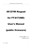
O C E A N S E R V E R
C O M P A S S
M A N U A L
Digital Compass Users Guide, OS5000 Series
P/N: 90-05000-00
REVISION 3.8
© 2007-2009 OceanServer Technology, Inc, 151 Martine St, Fall River, MA 02723 USA
www.ocean-server.com
[email protected] or [email protected]
1
O C E A N S E R V E R
C O M P A S S
M A N U A L
Table of Contents
Introduction to the Tiny Compass Family ........................................................... 3
OS Compass Design Features .......................................................................... 5
Specifications ..................................................................................................... 6
Electrical Connector and pin assignment........................................................... 8
Cables ................................................................................................................ 9
Communicating with the compass, RS-232 or USB......................................... 10
Output Sentence Formats ................................................................................ 11
Format Type 0x01, 1(10): “$C” format ............................................................ 12
Format Type 0x02, 2(10): “$OHPR” Sentence................................................ 13
Format Type 0x04, 4(10): “$HCHDT” Sentence.............................................. 13
Format Type 0x08, 8(10): “comma delimited” Sentence ................................. 13
Format Type 0x10, 16(10): Direct LCD Output ................................................ 13
Output Parameter Selection Table................................................................... 14
Terminal Emulation Programs for Communicating with the Compass ............. 15
Compass Command Summary Table .............................................................. 15
Compass Mounting Guidelines ........................................................................ 20
New Mounting Positioning with Firmware Version 1.5 and Later .................... 22
Calibrating the Compass.................................................................................. 24
Optional Soft Iron Calibration ........................................................................... 28
Installing Windows Demo Utility ....................................................................... 31
USB Drivers for the OceanServer OS5000-US family of compasses .............. 33
Basic Commands to Configure the OS5000 .................................................... 34
Depth or other sensor Connection for OS5000-USD ....................................... 35
PROGRAMMING NOTES................................................................................ 36
Customer Support ............................................................................................ 38
2
O C E A N S E R V E R
C O M P A S S
1
M A N U A L
Introduction to the Tiny Compass Family
The OceanServer precision 3-Axis Tilt Compensated compass products use
state of the art technology to provide outstanding performance and ease of use in
a low cost design.
The OS5000 family of compasses are a new class of sensor components providing
best in class performance for under $200.00 (USD) in low volume.
Features:
• Compass accuracy, 0.5 degrees RMS level heading,
1° RMS <±30° Tilt, 1.5° RMS <±60° Tilt,
.1 Degree resolution
• Roll & Pitch full rotation, typical 1° accuracy <±30° tilt
• Pitch Angles +/-90 degrees, Roll Angles +/- 180 degrees
• Tilt-compensated (electronically gimbaled)
• Tiny size, 1”x1”x0.3”, less than 2 grams weight
• Low Power Consumption, <30ma @3.3V
• Hard and soft-iron compensation routines
• Optional support for a high resolution Depth or Altitude sensor (24
bit AD)
• Serial Interface:
o RS232, USB or TTL
o Baud rate programmable 4,800 to 115,000 baud
• Rugged design
o 10,000 G shock survival
o -20° C to 70° C operating temperature (Accuracy specified
for 0° C to 50° C)
• ASCII sentence output, in several formats, NMEA checksum
• High Data Update Rate to 40HZ
• Support for True or Magnetic North Output
• Precision components
o 3 Axis magnetic sensors from Honeywell
o 3 Axis Accelerometers from ST Microelectronics
o 24 bit differential Analog to Digital converters from Analog
Devices
3
O C E A N S E R V E R
C O M P A S S
M A N U A L
o 50 MIPS processor supporting IEEE floating point math
OS5000-S -- Signals: RS-232 Levels: 3-Axis Compass, 1” x 1” size with full RS-232
support, single connector on the topside (note arrow imprinted on this side) of the
module.
OS5000-T -- Signals: TTL Levels: 3-Axis Compass, 1” x 1” size offers TTL only
support, single connector on the topside of the module
OS5000-US -- Signals USB or RS-232: 3-Axis tilt compensated compass, 1” x 1”.
Has both Serial & USB direct interface and has connectors on both sides of the
module.
Always mount compass with 7 pin side 1 up even when using USB connector
other mounting positions available with firmware version 1.5.
4
O C E A N S E R V E R
C O M P A S S
M A N U A L
Additional Note: the OS5000-USD version supports pressure measurement for depth
(not shown; utilizes same PCB and connectors as OS5000-US above).
OS Compass Design Features
Hardware Variants:
OS5000-S (RS232 Only), OS5000-US (RS232 & USB), OS5000-T (TTL
Only), OS5000-USD (Standard Features of –US Compass with Depth)
Magnetic Sensors:
Honeywell two-axis AMR sensor for X, Y plane sensing
Honeywell z-axis AMR sensor
Accelerometer, tilt sensor:
Three-axis STM accelerometer
Microprocessor:
50 MIPS processor that supports IEEE floating point operations for accurate
tilt compensation.
AD Conversion:
24 bit Sigma-Delta converters with differential inputs
All Models are RoHS Compliant Additional Note:
The OS5000 family of compasses is the next generation of compasses offered by
OceanServer Technology. The table below gives a cross reference to previous
generation parts:
Previous Generation Part
Replacement Part
Comments
OS1000
OS5000-S
Direct Replacement
OS1500 and 3500
OS5000-USD,-USDK
One part replaces both units
depth connected via Serial port
connector
OS3000
OS5000-US
Smaller 1’x1’ form factor
5
O C E A N S E R V E R
C O M P A S S
M A N U A L
Specifications
Parameter
Value
Azimuth accuracy
<0.5 deg RMS Level Heading, 0.1 deg resolution
Inclination (pitch and roll) Typical 1° accuracy <±30° tilt
accuracy
Inclination range
±80 degrees, (output for full rotation at decreased accuracy
pitch ±90 degrees, roll ± 180 degrees)
Temperature range
Accuracy specified for 0°C to 50°C, -40°C to +85°C
operation (decreased accuracy at temp extremes) Humidity:
20-80% RH non-condensing
Shock (Operating)
3,000 G, 0.5 ms, 10,000 G 0.1ms
Data Refresh Rate
0.01 Hz to 40Hz sentence output rate
Size
1” x 1” x 0.3” module
Weight
~ 2 grams
Supply Voltage
3.3V – 5VDC (Will operate with up to 15VDC using 3x the
power)
Power consumption
30 ma @3.3V (-S variant)
35 ma @5V (-US variant, in USB mode)
Serial Data Interface
RS-232C levels, TTL and USB 2.0 based on Variant
4800 – 115000 baud, 8 bit, 1 stop, no parity (19200 default)
Sentence Format
NMEA0183 Style, four sentence formats, supporting xor
parity ($HCHDT, $OHPR, $C, comma delimited.
Supports Acceleration & Magnetic sensor output in X,Y,Z
6
O C E A N S E R V E R
Magnetic
Routines
C O M P A S S
M A N U A L
Compensation Hard Iron and Soft Iron calibrations supported, note: Soft iron
(V1.4 or later firmware)
7
O C E A N S E R V E R
C O M P A S S
M A N U A L
Electrical Connector and pin assignment
OS5000-S, OS5000-US (TOP, Side 1 Serial Connector) and OS5000-T 7 pin, Molex
1.25mm connector (Molex: 51021-0700) – Available on. www.Mouser.com along with
pins and tool to make custom cables.
Description
Additional OS5000-T
(TTL version compass
notes)
Pin
Color
Signal
1
White
P-in
Pressure Input from Transducer same
(OS5000-USD only)
2
Black
GND
Ground
3
Red
VinDC Power Input, DC voltage same
Unreg in the range of 3.3V - 5V
4
Orange NC
RESERVED - Do Not Connect
same
5
Black
GND
Ground – Use with RS232
same
6
Green
Tx
RS-232 Transmit (DB9-F pin: 2)
Voltage Level TTL, 3V
drive level
7
Blue
Rx
RS-232 Receive (DB9-F Pin: 3 )
Voltage Level TTL, 3V or
5V tolerant on input
same
Note: Users that only require TX signal.
The OS5000 compass uses low power RS-232 transceivers, these will go
to sleep if the compass is not connected to a valid input level and
there will be NO compass output. If you would like to connect the
compass in TX only mode, i.e. no input RS-232 signal you should make
the following connection in the cable.
Compass RX (Blue wire), pin 7 should be connected to the Power
Input (Red wire) pin 3. This will keep compass TX (green wire) Pin 6
transmitting on it regular schedule.
8
O C E A N S E R V E R
C O M P A S S
M A N U A L
:OS5000-US USB and OS5000-USD, Bottom, side 2, 6 pin, single row header, Molex
1.25mm connector (Molex: 53261-0671) – Available on www.Mouser.com along with
pins and tools to make custom cables
Pin Color
Signal
Description
1
Green
USB
D+
2
White
USB
D-
3
Red
5V
Regulated USB Power
4
Black
Ground
USB Power
5
Reserved
Must be no connect
6
Reserved
Must be no connect
Cables
OceanServer offers a variety of cables, which come with the compass evaluation kits or
can be ordered separately. OS5000-US will auto detect whether the Serial or USB cable
has been plugged in.
Standard Cables:
19-00061-24, 24" OS5000-S Demo Kit Cable with Serial connection, Pressure and
3.6V battery power connection (picture below) Demo cable provides 3.6V battery
connection. Cable Note: this cable is a quick way to get the compass running for
evaluation. It is highly recommended that you operate the compass from 3.3V since
the module has a linear regulator and a higher voltage than 3.3V heats up the module
and wasting power and heating up the OS5000 module.
9
O C E A N S E R V E R
C O M P A S S
M A N U A L
19-00062-24, 24" OS5000-S/-T Series Pigtail Cable, 7 Pin connector, blunt cut (below)
19-00116-00, Aprox. 6’ OS5000-US Demo Kit Cable with USB to 6 Pin connector.
There is also a 3’ version available.
Communicating with the compass, RS-232 or USB
The USB compass requires device drivers to present itself to the system as an asynch
serial port, i.e. COMn: port on Windows. There are drivers supporting MAC OS and
Linux variants on the www.silabs.com web site, CP2102 bridge drivers. We provide
basic drivers and manuals on our web site for windows
www.ocean10
O C E A N S E R V E R
C O M P A S S
M A N U A L
server.com/compass/. At this point all compass designs present themselves as serial
port devices at a baud rate, 8 bits, 1 stop bit (ASYNCH).
Using a windows system open up a TeraTerm terminal emulator port to the compass
device. The factory default baud is 19200, 8, 1, N. This change has been made so
Windows OS does not mistakenly recognize the compass as a serial mouse. The baud
rate can be changed back to 9600 using the <Esc> B command
Output Sentence Formats
Figure: Compass output for each of the four supported output formats. The command
<esc>* lets you select the bit mask for the desired sentence format.
The compass is programmed with an output rate and it sends sentences at this fixed
rate. The rate is programmed with the <esc>R command. Values lower than 1 per
second use a negative number, -100 is 0.01hz, -10 is 0.1 hz, -2 is 0.5hz. Values greater
than 0 are in sentences per second, HZ. A value of 10 is 10hz, 40 is 40hz and so on. If
you program a rate of 0 the compass will cease output but still respond to <esc>
commands.
11
O C E A N S E R V E R
C O M P A S S
M A N U A L
Format Type 0x01, 1(10): “$C” format
$Chhh.hPpp.pRrr.rTtt.tMx0.000My0.000Mz0.000Ax000.0Ay000.0Az000.0*cc
$C212.4P2.5R-14.0T28.4Mx107977.90My-79422.00Mz173.27Ax0.045Ay0.245Az0.977*3A
This sentence format provides a text tag in front of each data type so the user program
can parse them accurately regardless of which data elements are activated. In effect
every data element has leads with its unique name.
Possible fields reported in the sentence (use the <esc>Xnnnnn<space> command to
configure the desired fields for output.
Hhh.h Heading in degrees, corrected for Declination if one is entered
Ppp.p: Pitch angle, “P” precedes the pitch angle in degrees
Rrr.rr Roll angle, “R” precedes the roll angle in degrees
Ttt.t: Temperature of the compass board, crude measure taken from the core
microprocessors internal sensor. Used for relative measurements of environments not
accurate. We provide a single point calibration offset using the <esc>+ command.
Standard Factory Format for OS5000-S, OS5000-US or OS5000-T
The standard setting below is <esc>*1<space> command
Example: $C320.5P0.2R-18.3T19.0*3C
Mx,My,Mz Magnetic field strength reported on each sensor. The units are calibrated to
milliguass by the user setting the local horizontal field strength before a full calibration.
Ax,Ay,Az Acceleration measured on all three sensors. The units are in “G” for each
sensor. You can also output the vector length (acceleration scalar) which will be close
to 1G
*cc This is the end of line character, the cc is the HEX X-OR sum of the characters
between the $ and the *. This is the NMEA standard format.
OS5000-USD Example: $C328.3P28.4R-12.4T21.1D21.01*<checksum> <cr><lf>
•
Compass heading: 328.3 degrees
•
Pitch angle: 28.4 degrees
•
Roll angle: -12.4 degrees
12
O C E A N S E R V E R
C O M P A S S
M A N U A L
•
Temp: 21.1 degrees
•
Depth: 21.01 feet [This is only output on the OS5000-USD ]
Format Type 0x02, 2(10): “$OHPR” Sentence
$OHPR value1,value2,value3,value4….*cc
The $OHPR sentence is activated with the <esc>*2<space> command. It provides a
comma-delimited list of all of the parameters selected for output with the <esc>X
command.
Format Type 0x04, 4(10): “$HCHDT” Sentence
$HCHDT,212.4,T*2C
The NMEA0183 standard true heading sentence is supported for output. The
$HCHDT sentence is activated with the <esc>*4<space> command. To have the
heading be true the user must program the compass with the local declination value
using the <esc>Qnnnn<space> where nnnn is the degress times 10 for local heading
offset. Example <esc>Q125<enter> will offset the heading 12.5 degrees for every
value reported.
Format Type 0x08, 8(10): “comma delimited”
Sentence
value1,value2,value3,va,….
This sentence outputs the data as a simple comma delimited list of the requested
values. This sentence is activated by the <esc>*8<space> command and it outputs all
data elements selected in the <esc>Xmask<space> command. This sentence format
is only available with firmware version 1.4 or later.
Format Type 0x10, 16(10): Direct LCD Output
Azimuth=0.0, Elevation=0.0….
In this mode the compass directly sends the data and formatting commands required
for a Crystalfontz 2x16 LCD display. This can be used in applications for antenna
aiming. In this mode the compass is temporarly mounted to the antenna in the field
and a cable then goes to a small handheld box with and LCD and a 9V battery. This is
all that’s needed create a very accurate antenna positing system. The compass is
13
O C E A N S E R V E R
C O M P A S S
M A N U A L
calibrated for a particular antenna frame to remove it’s soft are hard iron effects and
the compass will provide excellent results for quickly and accurately aiming antennas.
This sentence is activated by the <esc>*16<space> command. You should also
change the output rate to 2 (<esc>r set to 2) This sentence format is only available
with firmware version 1.5 or later.
Output Parameter Selection Table
(Note: not all compasses support all features)
Order Bit value (base 10) Parameter Name
1
1
Azimuth
2
2
Pitch Angle
3
4
Roll Angle
4
8
Temperature
5
16
Depth (feet)
6
32
Magnetic Vector Length
7
64
3 axis Magnetic Field readings, x,y,z
8
128
Acceleration Vector Length
9
256
3 axis Acceleration Readings, x,y,z
10
512
reserved
11
1024
2 axis Gryo Output, X,y
12
2048
Reserved
14
O C E A N S E R V E R
13
C O M P A S S
4096
M A N U A L
Reserved
Table: The output order and bit values for each of the possible output fields is
shown in the above table. The <esc>X
The <esc>Xmask<space> command uses a decimal mask. If you want heading, roll
and pitch active add the Bit Values up for the fields. I.e. 1+2+4=7, now use the
command <esc>X7<space> to enable these three fields. Remember the mask is
decimal so just add the bit field values up from the table.
Terminal Emulation Programs for Communicating
with the Compass
Hyperterm Issues: OceanServer compasses will usually show up as an additional
Hyperterm port when properly connected to a system. If the compass cannot be
communicated/programmed check to confirm the Hyperterm port has the correct
settings (baud is 9600, 8, 1, N (older compasses) or 19200 with firmware v1.1 or later).
If the settings are correct it could be a Hyperterm system issue and you may want to
download a different terminal program. One possible program is TeraTerm:
TeraTerm (Support Forum)
http://www.neocom.ca/forum/viewtopic.php?t=436
The install for version 4.51 and can be locate at
http://www.neocom.ca/freeware/TeraTerm/teraterm_utf8_451.exe
A windows version of Tera Term installer is located at www.oceanserver.com/compass/
Compass Command Summary Table
The compass is configured and calibrated using a set of commands sent to it via its
serial port connection. The general format of all commands to the compass are sending
it the ESCAPE command key, ASCII=27 decimal, noted as <esc> in this manual.
Type1: <esc>Kvalue<space>
Type2: <esc>K
15
O C E A N S E R V E R
C O M P A S S
M A N U A L
Where type 1 is the format for a command that has a value supplied. Note all values
are decimal integers examples: 10000, -1000, 2345. If the value needs a floating point
number such as heading we send it multiplied by 10.. Example: <esc>Q123<space> is
a value of 12.3 for heading.
The second type, Type2 is commands that immediately have some action. One
example is the calibrate command, <esc>C
Note1: Entering Commands -- Push the escape <Esc> key prior to a key command.
The command keys are CASE sensitive so if it asks for a “R” a “r” will not work.
Note2: Some command changes require the compass to be power cycled for changes
to take affect. Example, BAUD RATE CHANGE.
Key
Description of the command
Command
<Esc> B
BAUD RATE
Set new baud rate, 0-6, change takes effect after power cycle.
0=4800,1=9600,2=14400, 3= 192000, 4=38400,5=57600,6=115200
<Esc> R
SENTENCE OUTPUT RATE
Set the compass output rate, -50 to +40. Rate is in samples per second
and negative are seconds per sample. .i.e. 20=20 samples/second, 10=10 seconds per sample. A rate of 0 will stop output. At higher
output rates the baud rate will need to be increase beyond the standard
setting.
<Esc> X
OUTPUT DATA FIELD SELECTION
Fields to Display, bit mask of 5 bits (entered in decimal). 31=all active.
Sum up the values, Azimuth=1, Pitch=2, Roll=4,Temp=8,depth=16.
<Esc> Q
DECLINATION ANGLE INPUT FOR TRUE NORTH
This allows the user to specify an fixed heading offset to be applied to all
heading output data. In most cases this is used to adjust for local
compass deviation in your area. This information can be found on the
web using the World Magnetic Model and you local
LATITUDE,LONGITUDE. Enter Declination angle to create offset
for compass Azimuth. Value is 10x degrees. Example: -103=-10.3
degrees, 152=15.2 degrees.
http://en.wikipedia.org/wiki/Magnetic_declination
16
O C E A N S E R V E R
<Esc> C
C O M P A S S
M A N U A L
CALIBRATE HARD IRON X,Y SENSORS LEVEL PLANE
Calibrate the compass in the platform. Level the platform and prepare
to rotate it very slowly. When the output reports “XxYy” it is finding
new calibration data, keep rotation until you see only “.”’s output. You
MUST keep the platform level while you rotate. Validate the Roll and
Pitch angles are < 1 degree in the output string R0.x, P0.x before starting
<Esc> Z
CALIBRATE HARD IRON Z SENSOR ROLLED 90 Deg
Rotate your platform 90 degrees on it’s side. This will place the Z axis in
the same “earths” magnetic field the “C” calibration saw for the x,y
sensors. Perform once complete and slow rotation.
<Esc> H
or ? or h
<Esc> A
HELP MENU
Help Menu
FILTER HEADING, ROLL AND PITCH (non gyro compass)
Moving average filter on roll, pitch and heading. Enter the number of
samples to include in the average. This combined with output rate will
determine the period of the filter. Example: averaging = 5 output rate =
10 is half second period
<Esc> V
FIRMWARE VERSION
Displays the firmware version installed on this device
<Esc> +
CALIBRATE TEMPERATURE MEASUREMENT
Calibrate Temperature, offset in O.1C, example <esc>+-131<enter>
will subtract 13.1 from the reported temperature. Temperature is a crude
sensor and should not be used if accuracy is required, it is a good relative
measure of changes in the electronics rack.
<Esc> U
SCALE MAGNETIC FIELD OUTPUT
Calibrate and scale Raw Magnetic output, milliguass of horiz field
requires new calibration. The value you enter is the local horizontal field
strength of the earth’s magnetic field. After you enter this and do a
calibration the compass will output 3 axis magnetic sensor values in
milliguass. The local H field strength can be estimated using the NOAA
world magnetic model for you local area. You are basically providing
the compass with the value for the earths horiz field strength when it’s
calibrated. If you know this accurately you will get good results on the
17
calibrated data.
<Esc> D
DECIMATION FILTER FOR AD
Digital Filter Value for AD conversion, higher=longer filter time. The
default value is 3, using a higher value will add lag to the measurements
but filter noise. A value of D=1 provides the fastest update rate for
compass data, for example if you running at 40Hz update rate. The
value of D=3 is the default for the compass as it’s shipped. You will
also get less resolution at D=1 and more noise in the dat.
<Esc> *
OUTPUT SENTENCE FORMAT
Change Output Sentence Formats, bit mask, 1,2,4,8,16 are valid values.
Format 8 requires firmware version 1.4 or later, and 16 version 1.6 or
later, Deault=1.
*=2 is a simple NMEA like output with comma
delimited data, this is easy to tag and parse in user programs, *=4 is even
simpler comma delimited data with no sentence NAME or handle.
<Esc> %
CHANGE ESCAPE CHARACTER (*careful*)
Change Escape Character for compass, default=27=ESC *danger-careful* This is used to change the compasses ESCAPE character for
applications where the compass may be on a shared output line and the
system may send ASCII=27 characters. If you change it you will not be
able to talk to the compass unless you can send the new character value.
DON’T CHANGE THIS UNLESS YOU ARE SURE – HARDLY
EVERY NEEDED
<Esc> F
RESTORE FACTORY DEFAULTS
Restore Factory Defaults and calibration
<Esc> E
COMPASS ORIENTATION
Allows compass six mounting orientations to be set. The mounting
positions allow the user to mount the compass on all six sides on a box
for placing in locations where flat mounting is not possible. These are
shown graphically in a later section of this manual. Mounting options 16, E=1, Default flat.
This transformation is not possible on the OS5000-USDK compass
<Esc> a
ACCLEROMETER MAXIMUM RANGE
Change Accelerometer maximum measurement range. Options are 0-1;
default is 0 = 2G output; 1= 6G; Important Note: 6G output results in
less roll and pitch resolution. The 6G range should only be used if the
user is trying to measure the effects of X,Y,Z acceleration more than the
angle of the compass. The <esc>X command lets the user select
18
accleratoin vector and scalar data output.
<Esc> &
DUMP CONFIGURATION PARAMETERS
Dump all compass settings in a form that can be parsed or saved and
sent back to the factory when configuration questions arise.
FW_Version=V1.5
FW_Date=1-Jul-08
Serial_number=000765431
Test_date=01 Jan 08
Output_Format=1
Display_Fields=15
HW_Mounting_Pos=1
Baud_Rate=5
Set-Reset_Rate=8
Output_Rate=40
Averaging=0
…..
<Esc> $
SOFT IRON COMPENSATION
Soft Iron Compensation.
The values are 0=disable, 1=enable,
2=generate calibration. When you enter generate (2) you need to have
the system with the compass in installed and freshly calibrated, (via the
<esc>C,<esc>Z commands). You will need to align the system to
cardinal points according to a magnetic compass, N,S,E,W in an area
free of magnetic disturbance.
Note: You must have deviation set to 0 before this operation,
<esc>Q0<enter>
If you heading errors are very large before calibration, i.e. too much soft
iron very close to the compass, don’t expect anything to be able to do a
good job of fixing these.
<Esc> S
DEGUASS AND OFFSET RATE
Degauss every 'n' sentences. This sets the frequency of the sensor
degauss and offset operations. The default value is something around 1
second. The quicker you degauss the lower the compass lag is when
19
moving it quickly.
<Esc> T
The zero roll and pitch command will allow users to zero out both roll
and pitch. This can only be done for applications where pitch and roll
angles are < 3 degrees in a level platform.
Example Below:
$C330.7P0.8R-1.3T19.9*04
$C330.7P0.8R-1.3T19.9*04
CMD:T
Atempting to zero Roll,Pitch: Success.
Results above <space>
Flash Write
$C330.8P0.0R0.0T19.9*2C
$C330.8P0.0R0.0T19.9*2C
Important Note: Some commands may not be available in earlier firmware releases.
Compass Mounting Guidelines
In general you should mount the compass in a location in your vehicle or device that
has the least disruption to the earths magnetic field.
1) Remember if a low cost needle compass gives large errors in your platform a
very accurate compass will still measure these distorted fields with more
accuracy. Example: Low cost compass finds a 20 degree distortion at 90
degrees due to soft iron, we will find that this is actually 20.9 degrees! Soft
Iron correction will help but can only do so much.
2) Mount away from permanent magnets such as motors. The fields fall off as
inverse square of the distance so doubling the distance reduces the field
strength by ¼. (soft iron fixed)
3) Mount the compass away from moving magnetic fields such as wires carrying
current, moving magnets, generators, etc. (soft iron dynamic)
4) Mount the compass as far as possible from batteries and ferrous materials such
as iron and ni. Some aluminum is non-ferrous but some Al alloys have nickel
in them. (soft iron fixed)
5) Mount all compasses component side up (side 1 with arrow), level or true to
platform level with the arrow pointing forward. This is also the case when
using the USB connector on the OS5000-US.
6) Mount the compass in a mechanically stable location so this it moves with the
vehicle or device but doesn’t vibrate.
7) Metals such as aluminum, brass or copper do not block magnetic fields but
currents can still flow through them that could create unwanted local magnetic
fields. Metals such as iron and steel will distort the magnetic field.
20
OceanServer ships compasses with plastic standoff but users should insure that
the compass has sufficient distance from ferrous objects that could bend the
earth’s magnetic field and disrupt compass accuracy.
Aircraft Note: Most all electronic compasses use gravity to detect level and tilt with
accelerometers to measure tilt (including OceanServer compasses). The tilt angles are
determined by measuring the earth’s static gravitational vector. Since, dynamic and
static acceleration are indistinguishable when used in aircrafts with high acceleration
and banking turns, the dynamic acceleration will introduce an error in both roll and
pitch angle reported by the compass as well as heading errors. Only level headings will
be accurate when aboard a plane and vibration needs to be considered. Strong
vibration also applies acceleration to the compass and can cause errors if the amplitude
of the acceleration is significant as compared to the earth’s 1G acceleration due to
gravity.
Mounting Location Example:
In one real world example if the compass is mounted 2 inches from a paddle wheel
the compass will see up to 90 degrees of offset in heading due to the magnets moving!
Since the magnetic field falls off as the inverse square of the distance moving the
compass a small distance can make large improvements in the accuracy.
Mounting Distance (inches) Error (heading degrees)
-------------------------------2”
5”
9”
11”
-----------------------------90 degrees
10 degrees
1.6 degrees
0.2 degrees
So moving the compass 10+ inches from these moving magnets we were able to
remove all of the significant error introduced in your reading.
$C288.6P-0.2R-0.1T26.6*20
$C288.4P-0.2R-0.2T26.6*21
$C288.6P-0.2R-0.2T26.6*23
^^^^ Notice: Level in roll and pitch
CMD:C
Bridge offset
Calibrate X,Y <space> when done
XyxXyXyXYXyXyX.XXYxYY.xYxYxYxYxYxYxYxY.xYxYxYxYxYxYxY.xYxYxYxYxYxYxYx.YYxYxYxYx
YxYY.YYYYYYYY.YYXYXXYXYXX.XXXXXXX.XXXXXXXX.XXXXXXXX.X.yyy.......yy.yy.y.yyyy.yy.....X
XXX.XXX.X...Y.YYY.YY.YY.........xxx.x....................Flash Write
$C346.7P1.5R-0.1T26.9*06
$C335.7P-0.3R-90.0T26.9*10
$C335.7P-0.4R-88.4T26.9*1A
$C335.7P-0.4R-90.0T26.9*17
^^^^ Notice: Platform rolled 90 degrees, pitch 0
CMD:Z
Bridge offset
Calibrate Z <space> when done
zZzz.zZZZZZZZZZZZZZ.ZZZZZZZZZZZZZZ.ZZZZZZZZ..zzzz.zzzzzzzzzzzzzzzz.zzzzzzzzzzzzzzzz.zz
zzzzzzzzzz..........Z..Z................Flash Write
$C69.6P-0.4R-90.0T27.0*24
$C69.7P-0.4R-88.4T27.0*28
21
OS5000 Mounting hole locations (stand-offs shipped with compasses). Visit
OceanServer’s download page for 3D Models and Mechanical Drawings: www.oceanserver.com/download.html
New Mounting Positioning with Firmware Version
1.5 and Later
On firmware version 1.4 and earlier always mount the compass with 7 pin side 1 up
(this is the factory default mounting position for all firmware versions). Side 1 on all
compass models has the white arrow imprinted on the red etch. Firmware version 1.5
introduces 5 additional mounting positions for users that need the compass orientated
differently in their product. Note: The OS5000-USDK compass only supports
orientation #1.
Orientation #1 (Standard-flat) Factory Default
22
To change to another Orientation you will need to hit the Escape key and enter
command Key E. Below is the output factory default is 1 (Standard-flat).
CMD:E
** see manual, you MUST recalibrate compass after changing!
1: Standard-flat, 2:front, 3:port, 4:roof, 5:back, 6:starboard
Mounting Oriention (1..6)=1
Value and Enter, or Esc CMD:E
Below are figures for orientation Options 2-6. Once you have changed the orientation
you will need to recalibrate the compass starting with the XY calibration (then move
on to the Z) from the new orientation position. Note: Roll and Pitch should both
indicate zero values in the new orientation position prior to starting the XY calibration
and then roll the compass 90 degrees for the Z calibration.
Option #2 front (above)
Option # 3 Port (above)
23
Option # 4 Roof (above)
Option# 5 Back (above)
Option# 6 Starboard
Calibrating the Compass
Compasses operate by measuring the earth’s magnetic field and locating magnetic
north. When mounted in real platforms or devices there are other local magnetic fields
or materials that disrupt or offset the earth’s magnetic field. Sources to be aware of are
ferrous metal, electric currents and permanent magnets in electric motors.
24
There are two sources of magnetic field distortion: “Soft-iron” and “Hard-iron”.
“Soft-iron” effects are caused by un-magnetized ferrous materials in the area of the
compass. “Hard-Iron” effects are caused by magnetized ferrous materials near the
compass. “Hard-Iron” can be cancelled out by going through the rotational calibration
(described bellow). “Soft-iron” effects should be addressed during the design in phase
and compasses should be located away from such items to minimize impact to the
sensor. OceanServer compasses with firmware version V1.4 and later include a soft
iron calibration option. The soft iron correction routines work very well if the soft
iron effects are minimized. If you look at the measured data regarding distortion at a
distance in the earlier table you will see that the placement of soft iron a small distance
from the compass can make huge differences.
Magnetic Field Examples:
Undisturbed Magnetic
Field
Ferrous Material in Tail
Plus an Electric Motor
Creating Magnetic
Field Disturbance
Not an Ideal Place for
Compass Placement
Compass Placement
25
Non-Ferrous Bow
Least Magnetic
Field Disturbance
Best Place for
Compass
Placement
Users will need to calibrate the compass.
Step 1: Select appropriate location and install OceanServer Compass in device
IMPORTANT NOTE: Compasses require users to hit the < Esc > key prior to
each programming/calibration step. This has been added to prevent accidental
programming.
Step 2 Open a Hyperterm window to take two separate measurements (X-Y together,
followed by Z) for calibration. The Virtual terminal settings for the compass serial port:
19200 baud, 1 stop, no parity. We recommend TeraTERM free software. A Nema
string of data will begin outputting when connected properly (ie…“$C328.3P28.4R12.4T21.1D21.01)
Step 3 (Calibrating X, Y):
a. Check that the platform is level, observe Pitch (P0.x) and Roll (R0.x) data
and confirm they are less than 1 degree. Next, fully rotate the platform to make
sure it will remain level during the calibration process. The area should be
clear of soft and hard iron objects that could disrupt the earths magnetic field,
cars, motors, wires with current, magnets, etc.
Compass looking into
Back connector
Rotate 360 Degrees
Parallel to the Earth
X, Y Calibration
Ground
b. Calibrating X, Y: Enter <Esc> key, next enter uppercase “C” key and slowly
rotate the device at least one complete rotation for at least 20 plus seconds.
Note: the device should be kept as level as possible to calibrate the X, Y
magnetic sensing elements. Terminate sequence with SPACE bar key after you
have slowly rotated the device and observed the following output “…..” this
indicates you have found the “X,Y” max and “X,Y” min values.
26
c. Final X,Y Note: If the platform is not level during the calibration procedure
just abort (by hitting the SPACE bar) and re-run it. (i.e. Hit space and start at
step a above).
Step 4 (Z Calibration): Rotate device (90 degrees) so it is turned on its side
Rotate 90 degrees
Compass looking into
back connector
Next rotate 360 degrees
while at 90 degree angle
Z Calibration
Ground
a. Roll the platform 90 degrees, The area should be clear of soft and hard iron
objects that could disrupt the earths magnetic field, cars, motors, wires with
current, magnets, etc. You want the calibration to be done in the same place as
the “C” calibration as it needs to see the same earth’s magnetic field
b. Enter Z Calibration mode. Push <esc>Z on the keyboard. Slowly rotate the
device 360 degrees (at least one complete rotation). This step should take 20
plus seconds when you just get “…” you have found the “Z” max and “Z”
min values. Terminate the sequence by hitting the SPACE bar. Important
Note: The “Z” command should be done in the same location to calibrate and
align the Z axis sensor to the X, Y. This is important for tilt compensation.
Errors in heading, when the device is tilted, will result from no Z axis
calibration
Note: If the platform is not level during the calibration procedure just abort it and
re-run it. (i.e. Hit space and start at step 3 above). Compasses can also be
calibrated in the latest version of the OceanServer Windows Demo program. The
basic steps are the same as described above. The feature can be found under the
“program” button.
27
Optional Soft Iron Calibration
The above mentioned (C,Z) calibration routines do not compensate for soft iron
effects. Soft iron, batteries, wires with moving currents and other high permeability
materials in the near field cause these. These are generally far weaker than hard iron
effects. Choosing a good compass mounting location with distance from soft iron
structures should be attempted. In cases where the sensor will be impacted by soft
iron you should run the soft iron calibration (available starting with firmware version
1.4).
The soft iron compensation routine is started by hitting the <Esc> $ key command.
You want to select option 2 and follow the screen prompts (see example screen shot
below).
Important setup steps prior to running soft iron calibration:
Before starting the calibration, you need to have the system with the compass installed
and freshly calibrated, (via the <esc>C,<esc>Z commands). You must have
declination set to 0 before soft iron calibration begins, check setting by <esc>Q and
make change to 0 if necessary then hit <enter>. You will need to align the system to
the four cardinal points according to an accurate reference magnetic compass, 0 North,
90 East, 180 South, 270 West in an area free of magnetic disturbance. Once you have
your device or system properly aligned, starting at 0 North, you want to start the soft
iron correction with the <esc>$ command followed by entering 2. Actual calibration
routine shown below.
28
After you run through the calibration process, you will see the correction values
generated by the process. At this point, the soft iron calibration is completed. You
should go back and check the cardinal points with your system. You should see your
system more inline with the cardinal points.
If the compass is still not reporting accurate information compared to the known good
reference compass you should run through the calibration process again and carefully
check each step. In some cases, the magnetic field may be too disturbed for accurate
calibration and distance from soft iron is the best solution.
Compass Settings Relating to Filtering Measurements (Not Required for
Most Applications):
------------------------------------------------------------------------------Since the OS5000 family of digital compasses use a fast 3-axis accelerometer to
sense the gravity (1G) static vector to determine its Roll and Pitch angle you may
need to filter out other dynamic acceleration introduced by your platform. These
accelerations will decrease the accuracy of the Roll and Pitch estimation using
Euler angles. Introducing filtering will improve the accuracy if the platform
acceleration is dynamic and can be filtered out.
1) Analog to Digital Converter Decimation Filter
The analog to digital converter is an AD7799 24 bit Sigma delta converter. It has
an internal decimation filter that sets the filter period and the sampling update
rate.
The lower the setting the faster the update rate can be. If your using a
40hz output rate you should set this value from 3 to 2.
<esc>D (1-9) enter ! to change the update rate
1: 470 Hz, 4ms settling time
2: 242 Hz, 8ms settling time
3: 123 Hz, 15 ms settling time (factory default)
4: 62 Hz, 32 ms settling time
5: 50 Hz, 40 ms settling time
6: 39 Hz, 48 ms settling time
7: 33.2 Hz, 60 ms settling time
8: 19.6 Hz, 101 ms settling time, 90 dB rejection of 60Hz noise
9: 16.7 Hz, 120 ms settling time, 90 dB rejection of 50Hz noise
Use the higher values if you have large electrical or vibration noise you need to
filter out, at a much lower update rate.
(2) Averaging of readings, n Sample in the average
This will be a moving average filter of the magnetic readings and the
accelerometer readings. A value of 1 sample is no filtering, the default is 6 with an
29
output rate of 10 samples per second. The output rate of samples per second
combines with the number of samples in the average to give you the lag in
response time of the output. On the depth version (OS5000-USDK) this is set to
1.
(3) Output rate of the compass sentences, n samples per second.
Values that are negative are for less than one sample per second. You can set this
from -40 (1 sample every 40 seconds) to -2 (1 sample every 2 seconds). If the
values are positive this is number of samples per second. The range is 1 (1 sample
per second) to 40 (40 samples per second, 40 hz).
<esc>R n <enter> ! change the output rate of the compass to n
If your using output rates of greater than 20 hz you should change the D filter
value to 2 or 1.
Temperature Calibration (not required)
----------------------------------The OS5000 reports its temperature from the sensor inside of the modules 50
MIPS microprocessor. It is affected slightly by the operating voltage of the
module. It may require a linear offset to make it align with ambient temperature.
Using the command <esc>+ ttt <enter> you can offset this temperature. Enter
the value in degrees Cx10.. Example: 25 will add 2.5 degrees C to the
measurement. -92 will deduct 9.2 degrees C. Note: This calibration step is not
required and is for users looking for better temperature accuracy.
Calibration of Raw Magnetic readings in milliguass (not required)
------------------------------------------------------------------------You can set the milligauss of the Horizontal earths magnetic field using the
<esc>U mmmm <enter>. This is milliguassx10. Example 1794 for 179.4
milligauss. You can use the NOAA provided web model using your latitude and
longitude and nanoTesla Horizontal for the earth’s field in your local area.
Convert this to milligauss (divide by 100). Make this change in compass settings
before you calibrate the compass and the magnetic vector output will be in
milliGuass. NOAA Link:
http://www.ngdc.noaa.gov/seg/geomag/jsp/IGRFWMM.jsp?defaultModel=WMM
M210.12,Mx121.21,My12.12,Mz171.1
M=Vector Intensity
Mx=X component
My=Y component
Mz=Z component
Acceleration Raw Output Data
-----------------------------------------The acceleration raw data in G's can be output. The format is as follows:
G1.001,Gx0.621,Gy0.212,Gz0.754
30
G=Gravity vector, will be close to 1 if no dynamic acceleration present
Gx=X axis component of acceleration in G's
Gy=Y axis component of acceleration in G's
Gz=Z axis component of acceleration in G's
The "G" vector overall length will tell you if the platform is stable or experiencing
dynamic acceleration. Any dynamic acceleration changes the vector length from
near 1 to a lower or higher value.
Configuring the output sentence of the compass (Not Required)
--------------------------------------------------------------------The <esc>X {decimal} <enter> command will let you set the bit mask of what
values the compass outputs. If you enter the max value of 4095 (all 12 bits set)
the compass will output all values. Use the Compass Demo program to help your
set this field on the compass. The program can be downloaded from:
www.ocean-server.com/compass/
Installing Windows Demo Utility
The windows demo utility is located on the web. Download the
CompassDemo5000.zip file and open it. This installer will put the compass demo
program on your system.
www.ocean-server.com/compass/
31
Main Screen:
Configuration Screen
32
Program Screen (allows for calibration, custom screen displays and other settings)
USB Drivers for the OceanServer OS5000-US
family of compasses
You must download the USB drivers for windows directly from our web site.
These are only required if your using the USB interconnect option on the
OS5000-US compass. Remember if you have an OS5000-US it supports either
RS-232 serial or USB by selecting the correct cable. There are two connectors on
the module. The serial connector is on the TOP side and is 7 pin, the USB cable is
6 pins and on the bottom side of the module.
The standard USB dirvers can be downloaded from www.silabs.com
CP210x VCP Drivers
Drivers for Windows, Mac and Linux
33
www.ocean-server.com/compass/
Our demo program runs on Windows only but on all other operating systems you
can open a terminal program to the virtual serial port and talk/listen to the
compass with it's NMEA strings.
If you would like a method to test the OS5000-T (TTL only) with a RS232 com
port on a PC, Black Box Networks offers a RS232 to TTL converter (PN#
IC1157A). Link:
http://www.blackbox.com/Catalog/Detail.aspx?cid=308,1421,1547&mid=4062
Basic Commands to Configure the OS5000
1) Mount the compass in the best location away from ferrous materials
2) Configure the compass firmware (hit <Esc> key prior to any command key)
a. Talk to the compass using a terminal program such as “Tera term”,
Settings: 19200,8,1,N to the device (9600 with firmware v1.0 ).
b. “<esc>V” Check firmware version
c. “<esc>B” Set compass baud rate (Active after power cycle)
d. “<esc>C” calibrate X,Y (rotate 360+ in 15+seconds, level X,Y)
e. “<esc>Z” Calibrate X (tip platform on side, rotate 360+)
f. “<esc>Q” Set the Declination value if you want “True magnetic
output” – This will offset for the delta between magnetic north and
true north.
g. “<esc>R” set the output rate for your application
34
h. “<esc>*” set user sentence format, 1,2,4,8
i.
“<esc>$” soft iron calibration, align system to N,S,E,W magnetic
j.
“<esc>A” Set averaging to smooth the readings
Note: These are the most common commands used (configurations will vary).
Depth or other sensor Connection for OS5000-USD
OS5000-USD connection with MSI pressure transducer, sensor outputs 0.5 - 4.5V.
OceanServer compass has an internal series resistor divider to change voltage range to
0 – 2.5V (3K+3K ohm series) for its internal AD conversion.
Note: See page 7 for assignment of pins 3-7.
OS5000-USD commands: <esc> M nnnn <enter> enter max pressure for sensor PSI
<esc>P<space> set zero depth, pressure output via 24 bit AD, resolution in 0.01 feet.
Note: Depth assumes fresh water, no internal density correction. If M0<enter> is set
the device will output the sensor voltage for use with non-depth sensors. One example
would be an altitude sensor for airborne applications.
Remember the OS5500 pressure input (white wire) has an internal voltage divider to
allow an external 0.5 – 4.5V signal to be input to the OS5000-USD’s AD. The
resistance values are two 3K resistors in series to ground (6K resistance to ground.).
The output of your sensor must consider this divider in it’s output drive circuit.
35
PROGRAMMING NOTES
OceanServer offers developers a Source Code Example Program that communicates
with the OS5000 compass under Windows. This program can be downloaded from
OceanServer download page. http://www.ocean-server.com/download.html
The source code program configures and operates a serial port, reads the compass
configuration, allows for sending commands and configuring the compass. The
program is written in Microsoft Visual Studio C#. This compiler can be downloaded
in trial from Microsoft.com
NMEA CHECKSUM GENERATION
1-
Example of checksum calculations in VisualBasic
Returns True if a sentence's checksum matches the
calculated checksum
Public Function IsValid(ByVal sentence As String) As
Boolean
' Compare the characters after the asterisk to the
calculation
Return sentence.Substring(sentence.IndexOf("*") +
1) = GetChecksum(sentence)
End Function
36
' Calculates the checksum for a sentence
Public Function GetChecksum(ByVal sentence As String)
As String
' Loop through all chars to get a checksum
Dim Character As Char
Dim Checksum As Integer
For Each Character In sentence
Select Case Character
Case "$"c
' Ignore the dollar sign
Case "*"c
' Stop processing before the asterisk
Exit For
Case Else
' Is this the first value for the checksum?
If Checksum = 0 Then
' Yes. Set the checksum to the value
Checksum = Convert.ToByte(Character)
Else
'
No.
XOR
the
checksum
with
this
character's value
Checksum
=
Checksum
Xor
Convert.ToByte(Character)
End If
End Select
Next
' Return the checksum formatted as a two-character
hexadecimal
Return Checksum.ToString("X2")
End Function
2-
Example of checksum calculations in C
// Returns True if a sentence's checksum matches the
// calculated checksum
public bool IsValid(string sentence)
{
// Compare the characters after the asterisk to the
calculation
return sentence.Substring(sentence.IndexOf("*") +
1) ==
GetChecksum(sentence);
37
}
// Calculates the checksum for a sentence
public string GetChecksum(string sentence)
{
// Loop through all chars to get a checksum
int Checksum = 0;
foreach (char Character in sentence)
{
if (Character == '$')
{
// Ignore the dollar sign
}
else if (Character == '*')
{
// Stop processing before the asterisk
break;
}
else
{
// Is this the first value for the checksum?
if (Checksum == 0)
{
// Yes. Set the checksum to the value
Checksum = Convert.ToByte(Character);
}
else
{
// No. XOR the checksum with this character's
value
Checksum
=
Checksum
^
Convert.ToByte(Character);
}
}
}
// Return the checksum formatted as a two-character
hexadecimal
return Checksum.ToString("X2");
}
Customer Support
Send technical questions to: [email protected]
OceanServer Technology, Inc, 151 Martine St, Fall River, MA 02723 USA
Copyright © 2007-09 by OceanServer Technology, Inc. All Rights Reserved.
38