1
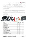
Introduction .............................. 3
Warning Cautions and Notes ... 3
Define. 3
Warnings .. 3
System Overview Packing List .
Functional Overview ..
Component Overview 4
4
5
6
Recorder .. 6
Power Supply .. 7
DVI Harness 7
Installation 8
Connections . 8
Datatoys XM-DVR Pro
Dual Channel Recorder
DVR Connections .... 9
DVI Connections .. 10
Recorder Installation ... 11
Power Supply Installation ... 12
Camera Installation . 13
Cable Installation . 13
Using the System 14
Before you begin . 14
Recording .. 14
Reviewing Events .................... 15
DVR Playback 15
Connecting a Monitor. 15
Event Playback .. 16
PC Playback .. 17
Transferring Events .. 17
Playing Events ... 18
Editing Events ... 18
Menu and Settings .. 19
Remote Control 19
On-Screen Display .. 20
Setup .. 21
Audio/Video 22
Alarm ... 23
Clock 24
Zones .. 24
Storage 25
Password 25
OSD . 26
System . 26
Factory Default .. 26
Playback . 27
Plan . 27
About .. 27
Camera Settings 28
Proudly Made in Milwaukee, WI
Troubleshooting ...29
Accessories .. 30
Warranty 31
Contact ... 31
User Manual
XM-DVR Pro Dual Channel DVR
December 2009
Page 1 of 32
Manual Rev 3.05
XM-DVR Pro Dual Channel DVR
December 2009
Page 2 of 32
Manual Rev 3.05
Introduction
System Overview
Congratulations on your purchase of the Datatoys XM-DVR Pro! The XM-DVR
Pro the highest quality MPEG2 recorder available, with an advanced encoding
algorithm and one of the highest bit rates. The XM-DVR Pro is used world wide in
film, aviation, military, motorsports and many other applications.
Packing List
This manual will guide you through the set-up, use, and care, of your XM-DVR
Pro and its’ many accessories.
XM-DVR Pro kits come with everything you need to get started, less a compact
flash memory card. Due to the large data-rate of the XM-DVR Pro, we recommend
using EXCLUSIVELY the RiData 300X compact flash cards. It is strongly
recommended that you purchase these cards directly from Datatoys or an authorized
RiData dealer.
Warnings, Cautions, and Notes
Define
•
•
WARNING Procedures, techniques, etc, which could result in personal
injury or death if not carefully followed
•
CAUTION Procedures, techniques, etc, which could result in damage to
equipment if not carefully followed.
•
NOTE Procedures, techniques, etc, which shall receive special
emphasis.
WARNING All components must be positively mounted to withstand high g-load,
shock, and vibration. In the event of high g-load, improperly mounted
components may become detached causing serious injury or death. All
components must be checked for safe and secure mounting before each use.
•
WARNING Before connecting the XM-DVR Pro to a power source, all batteries
and power supplies must be disconnected. All engines and alternators must be
turned off and you must ensure there is no live power running through the circuit
to which you are connecting.
•
WARNING All wires, cables, and connections must be adequate and rated to
supply at least 32VDC at 10AMPS. Using underrated or improper cabling and
connections could result in a fire.
XM-DVR Pro Dual Channel DVR
December 2009
Page 3 of 32
Manual Rev 3.05
The XM-DVR Pro is available in four variants:
DT-XMDVR-DIY
(DIY)
DT-XMDVR-BASE
(Base)
DT-XMDVR-PLUS
(Single Cam)
DT-XMDVR-PLUS2
(Dual Cam)
DT-XMDVR-DIY
1 – DT-XMDVR-PRO
1 – DT-XMDVR-USB2
1 – DT-XMDVR-DOCS
XM-DVR Pro Recorder
USB 2.0 Cable
Software and Documentation
DT-XMDVR-BASE
1 – DT-XMDVR-DIY
1 – DT-XMDVR-2CH
1 – DT-XMDVR-DCDC
1 – DT-CABLE-7
1 – DT-XMDVR-RMOTE
XM-DVR Pro DIY Kit
Two Channel DVI Harness
DC to DC Power Supply
RCA AV-OUT Cable
IR Remote Control
DT-XMDVR-PLUS
1 – DT-XMDVR-BASE
1 – DT-CAM-E580
1 – DT-MNT-SPRCMP
1 – DT-MNT-UNI
1 – DT-MNT-CLICK
1 – DT-CABLE-2M
XM-DVR Pro Base Kit
Sony 580 Line Bullet Camera
SuperClamp Mount
Universal Mount
Click Mount Adapter
2 Meter Extension Cable
DT-XMDVR-PLUS2
1 – DT-XMDVR-PLUS
1 – DT-CAM-E580
1 – DT-MNT-SPRCMP
1 – DT-MNT-UNI
1 – DT-MNT-CLICK
1 – DT-CABLE-2M
XM-DVR Pro Plus Kit
Sony 580 Line Bullet Camera
SuperClamp Mount
Universal Mount
Click Mount Adapter
2 Meter Extension Cable
XM-DVR Pro Dual Channel DVR
December 2009
Page 4 of 32
Manual Rev 3.05
Functional Overview
•
Component Overview
The XM-DVR Pro is a dual channel digital video recorder which can record two
composite video signals and two stereo audio signals simultaneously to one or
two compact flash cards, hard drives or solid state drives. Video signal can be
supplied from any camera with a standard composite video output.
•
The XM-DVR Pro can begin recording by one of four methods; on power up,
controlled via an external switch, via RS232, or by the IR remote control.
•
The XM-DVR Pro records the video and audio files to media in a secure format
which can be transferred to a PC via the DVR2PC software. Once transferred the
files can be viewed with any MPEG2 media player or burned to a DVD. The XMDVR Pro can also playback all files through the standard RCA AV-OUT using the
infrared remote control.
•
The XM-DVR Pro configuration and setup is performed through the menu that is
accessible through the AV-OUT. The menu will appear on screen and settings
can be changed via the infrared remote control.
XM-DVR Pro Recorder
•
•
•
•
•
•
XM-DVR Pro Dual Channel DVR
December 2009
Page 5 of 32
Manual Rev 3.05
DVI Connector: Mates with DVI Harness to connect all external devices to the
XM-DVR Pro.
Power Connector: Mates with power supply to provide power to the recorder,
cameras, and accessories.
CF Slot 1 & 2: House master and slave (optional) CF cards. Slave can be set to
overflow or dedicated to channel 2.
USB 2.0: Mates with USB 2.0 cable for file transfer.
IR Sensor: Receives infra-red signal from remote control for programming and
playback functions.
Active Light: Indicates record and ready activity.
o Ready:
Slow Blink, 1500ms/
o Recording:
Fast Blink, 500ms/
XM-DVR Pro Dual Channel DVR
December 2009
Page 6 of 32
Manual Rev 3.05
Power Supply
•
•
•
Installation
Power: Mates with Power Connection on the
XM-DVR Pro. Supplies 5VDC for recorder
and 12VDC for cameras and accessories.
+VDC: Connects to +10 to 32VDC power
connection rated at a minimum of 30 watts.
GND: Connects to ground associated with
+VDC circuit.
CAUTION: Safe and proper installation is the responsibility of the owner and user.
Please follow the connection and installation instructions to insure proper function and
performance.
Before you begin installation, please check that all items were included per the
packing list on page 4. Lay out all components on a large open surface and
familiarize yourself with the items and their connections.
DVI Harness
•
•
•
•
•
•
•
DVI: Mates with DVI Connector on the XM-DVR Pro
AV-OUT: Mates with AV-OUT cable or monitor.
SWTCH: Mates with patch cable or record stop/start switch.
CAM-2: Mates with patch cable, video input cable, or camera.
CAM-1: Mates with patch cable, video input cable, or camera
MIC-1: Mates with patch cable, audio input cable, or microphone
MIC-2: Mates with patch cable, audio input cable, or microphone
XM-DVR Pro Dual Channel DVR
December 2009
Page 7 of 32
Manual Rev 3.05
Connections
Please refer to diagram below for proper connection of your XM-DVR Pro and its
components. All connections are indexed and should be hand tightened. Extension
cables can be added to any Datatoys 4-PIN connection.
XM-DVR Pro Dual Channel DVR
December 2009
Page 8 of 32
Manual Rev 3.05
DVR Connections
DVI Harness Connections
Video Connections: Two (2) composite video
connections can be found on the DVI Harness in the
form of a female 4-PIN connector. This connection
mates with Datatoys cameras and extension cables.
Adapter cables are available at www.datatoys.com for
use with non-Datatoys cameras.
Audio Connections: Two (2) Line level stereo audio
connections can be found on the DVI Harness in the form
of a male 4-PIN connector. This connection mates with
Datatoys microphones, audio cables, and extension
cables. Adapter cables are available at www.datatoys.com
for various audio inputs.
Power Connector: The power supply connects to the
power connector on the back of the recorder and should
be screwed hand tight. This power connection will supply
the XM-DVR Pro, cameras, microphones and auxiliary
devices with power.
Audio Video Output Connection: One (1) AV-OUT
connection can be found on the DVI-Harness in the form
of a male 4-PIN connector. This connection mates with the
AV-OUT cable or Datatoys monitor and supplies a
composite video and stereo audio to an external screen.
Main DVI Connection: All other external devices are
connected to the recorder through the DVI Harness.
This allows for quick and easy removal of the DVR from
the vehicle. The DVI harness should be secured to the
recorder by fastening both thumbscrews, by hand, into
the back of the recorder.
XM-DVR Pro Dual Channel DVR
December 2009
Switch Connection: One (1) Switch connection can be
found on the DVI-Harness in the form of a male 4-PIN
connector. This connection mates with the record
stop/start switch to control recordings. An event can be
triggered by connecting TRG 1,2, or 3, to ground.
Page 9 of 32
Manual Rev 3.05
XM-DVR Pro Dual Channel DVR
December 2009
Page 10 of 32
Manual Rev 3.05
Once you are familiar with the components and their respective connections it is
time to select the best location to install the system on the vehicle.
•
The XM-DVR Pro recorder should be mounted such that it is shielded from
the elements and near a power source in an orientation that allows access to
the media bays.
•
The power supply should be mounted close to the recorder and near a high
current power source. The power supply should also be shielded from the
elements.
•
E580 bullet cameras can be mounted virtually anywhere on the vehicle
affixed to a solid base. E580 cameras are waterproof, shielded, and
hardened for harsh environments.
•
Cabling should be routed in such a way that avoids RF and EMI
interference. To avoid interference, cabling should be routed such that it is
shielded from communication devices by a ground plane. If cabling must
cross a communications cable it is recommended you cross perpendicular to
the interfering cable and at no point run along a cable capable of producing
interference.
Power Supply Installation
WARNING All components must be positively mounted to withstand high g-load,
shock, and vibration. In the event of high g-load, improperly mounted components
may become detached causing serious injury or death. All components must be
checked for safe and secure mounting before each use.
WARNING Before connecting the XM-DVR Pro to a power source, all batteries and
power supplies must be disconnected. All engines and alternators must be turned off
and you must ensure there is no live power running through the circuit to which you
are connecting.
WARNING All wires, cables, and connections must be adequate and rated to supply
at least 32VDC at 10AMPS. Using underrated or improper cabling and connections
could result in a fire.
CAUTION The XM-DVR Pro Power Supply must be mounted in a dry area as
exposure to water may damage components and will void the warranty.
Recorder Installation
CAUTION: Do not apply power to the power supply until installation is complete and
there are no loose or unsecure connections.
WARNING All components must be positively mounted to withstand high g-load,
shock, and vibration. In the event of an accident, improperly mounted components
may become detached causing serious injury or death. All components must be
checked for safe and secure mounting before each use.
The XM-DVR Pro Power Supply should be positively mounted near the XM-DVR
Pro such that the appropriate power connections may mate with out excessive
tension in the line. Suggested mounting methods include, tie wraps, high strength
Velcro, or metal fasteners.
CAUTION The XM-DVR Pro recorder must mounted in a dry area, exposure to water
may damage components and will void the warranty.
The XM-DVR Pro is designed to be mounted with 10-24 or 10-32 bolts through
the four mounting holes in the front and rear plates of the DVR. The XM-DVR Pro can
be mounted in any orientation while maintaining access to the media bays and
clearance for connections.
The power supply is equipped with two flying leads; red and black opposite the
power connector. The red lead must be connected to +VDC from a source capable of
supplying 10-32VDC and at least 30 watts. The black lead must be connected to –
VDC (ground). When connecting the power supply to a power source, it is
recommended you use a 5A fuse on the +VDC (RED) line. All connections must be
properly insulated to avoid electrical shorts.
XM-DVR Pro Dual Channel DVR
December 2009
Page 11 of 32
Manual Rev 3.05
XM-DVR Pro Dual Channel DVR
December 2009
Page 12 of 32
Manual Rev 3.05
Camera Installation
Using the System
WARNING All components must be positively mounted to withstand high g-load,
shock, and vibration. In the event of high g-load, improperly mounted components
may become detached causing serious injury or death. All components must be
checked for safe and secure mounting before each use.
Before You Begin
Before you begin using the XM-DVR Pro please complete the following check
list.
Cameras can be mounted virtually anywhere on the vehicle. Datatoys bullet
cameras are waterproof, shielded, and completely potted for vibration resistance. It is
recommended you mount the cameras in a central mounting position help with image
stabilization.
Using a RiData 300X card purchased from an authorized dealer.
Recorder is installed per the installation instructions.
Power supply is installed per the installation instructions.
Cameras are installed per the installation instructions.
Cabling is installed per the installation instructions.
Connections are made per the installation instructions.
All WARNINGS, CAUTIONS, and NOTES have been reviewed and followed.
Cable Installation
WARNING All components must be positively mounted to withstand high g-load,
shock, and vibration. In the event of high g-load, improperly mounted components
may become detached causing serious injury or death. All components must be
checked for safe and secure mounting before each use.
Once the checklist is completed you may insert the memory card into CF-1 and
apply power to the system. After booting the system it is recommended you connect a
small monitor to the AV-OUT using the AV-OUT adapter cable which will allow you to
configure the on-screen menus and align cameras. See page 15 for instructions.
CAUTION All connections must be hand tightened. Over tightening of connections
may damage the internal water seal of the connector.
Recording
CAUTION Sharp edges of zip ties or cable wraps may sever or create a short in the
cabling. Zip ties and cable wraps must not be over tightened.
CAUTION Never insert or remove a memory card from the XM-DVR Pro while power
is being supplied to the unit. This may damage equipment and render your recordings
useless.
All Datatoys cabling features a 4-PIN, waterproof, positive locking, male or
female connection. Patch cables may be used to extend any Datatoys 4-PIN
connections. Please refer to the table below to ensure cabling is routed in the proper
orientation.
Device
Camera
Microphone
AV-Out
Switch
Gender to mate with
DVI harness
Male
Female
Female
Female
Gender to mate
with device
Female
Male
Male
Male
Cabling should be attached to a solid structure with zip ties, or cable wrap. At no
point should Datatoys cabling route in parallel with cabling or devices emitting EMI/RF
interference. When cabling must cross an EMI/RF emitting line their intersection
should perpendicular to one another.
Once cabling and all other components are installed, connect the system per the
connection instructions on page 8.
XM-DVR Pro Dual Channel DVR
December 2009
Page 13 of 32
Manual Rev 3.05
NOTE You will lose 0-30 seconds of the end of your recording if you shut off power
while the unit is recording.
After powering on the system the unit will take 20-30 seconds to boot. Once
booted unit will then enter one of two states indicated by the amber active light;
•
•
Ready:
Recording:
Slow Blink, 1500ms/
Fast Blink, 500ms/
The state is dependant upon the switch
input and alarm settings in the DVR menu. To
configure switch settings please see page 23.
If your DVR is configured to record on power up, the unit should automatically
begin recording when no switch is connected. To stop the recording you may simply
cut power to the XM-DVR Pro. When power is cut the unit will automatically close the
file from the last archive point.
XM-DVR Pro Dual Channel DVR
December 2009
Page 14 of 32
Manual Rev 3.05
Event Playback
If your DVR is configured to record from the command of a stop/start switch the
unit will start recording based on the state of the switch. If the switch is in the on
(closed) position upon boot the unit will automatically begin recording. To stop the
recording, simply flip the switch to the off (open) position.
NOTE To boot, the DVR must be powered by a 10-32VDC supply capable of
supplying at least 3A at 12VDC.
NOTE For playback, it is recommended you disconnect all cameras to; halt
recordings, reduce power draw, and reduce processing load on the DVR.
Reviewing Events
CAUTION Never insert or remove a memory card from the XM-DVR Pro while power
is being supplied to the unit. This may damage equipment and render your recordings
useless.
Once a monitor is connected, insert the compact flash card, and boot the DVR.
The DVR will take 20-30 seconds to boot and you will see the splash screen appear
on the monitor. Use the IR remote included with your system and press Menu twice to
evoke the main menu.
You may review events using one of two methods, DVR Playback or PC
Playback.
•
DVR playback allows you to view your recordings on a monitor or television.
•
PC playback allows you to watch your recordings on your PC or burn them
to a DVD.
DVR Playback
Connecting a Monitor
To playback your recordings using the DVR you must first connect a monitor or
television to the AV-OUT on the DVR. If you are using a Datatoys monitor please
follow the setup instructions included with the monitor and skip to the next step. If you
are connecting to your own television or monitor follow the instructions below.
Navigate to Playback. Scroll to Show Event List and press the right arrow to
execute. Events will be listed in chronological order. The dark blue bar at the bottom
of the menu will display Zone, Channel, Type and Event length.
Included with your kit is the AV-OUT cable which
converts the Datatoys 4-PIN connection to a universal
RCA type connection. First connect the 4-PIN
connection of the AV-OUT cable to the AV-OUT
connection on the DVI harness. The AV-OUT lead is
located on the DVI harness which connects to the
back of the DVR as seen on page 9.
To select a recording press Enter. Then press PLAY to initiate playback. Use the
remote instruction on page 19 to perform all basic playback functions such as; fast
forward, rewind, stop, and pause. To exit, press Menu, or Cancel.
Then connect the appropriate RCA connections to the
video input on your television or monitor. This may
require the use of an RCA extension cable which is
available at any electronics store.
XM-DVR Pro Dual Channel DVR
December 2009
Page 15 of 32
Manual Rev 3.05
XM-DVR Pro Dual Channel DVR
December 2009
Page 16 of 32
Manual Rev 3.05
PC Playback
Playing Events
You can also playback files using your PC. This can be done by connecting the
DVR or CF card to your PC, transferring the files, and then playing in an appropriate
media player or burning a DVD.
Once events are downloaded they may be opened with any media player
capable of playing MPEG2 type files. We recommend downloading VLC free media
player at http://www.videolan.org/vlc/download-windows.html .
For optimal playback it is recommended you deinterlace files while viewing. In
VLC this can be done by clicking Video>Deinterlace>Blend
Transferring Events
CAUTION Never insert or remove a memory card from the XM-DVR Pro while power
is being supplied to the unit. This may damage equipment and render your recordings
useless.
CAUTION Never explore or tamper with the CF drive outside of the DVR2PC
application. This may corrupt recordings, destroy setup files, and render the drive
useless.
NOTE For best download results use a USB2.0 port located on the back of your PC.
Before you can transfer video events to your PC, you must first install the
DVR2PC file transfer application. This is available at datatoys.com/support.php and
can also be found on the software disk that was included with your system. Please
see the DVR2PC install video or PDF guide for more information on the installation of
this program.
NOTE To boot, the DVR must be powered by a 10-32VDC supply capable of
supplying at least 3A at 12VDC.
Once DVR2PC is installed you must connect the DVR or CF card to your PC. If
you have a compact flash card reader simply insert the card into the reader and
connect the reader to your PC. Your PC should automatically recognize the drive.
If you are downloading directly from the DVR you must insert the compact flash
card and boot the DVR. Once the DVR is fully booted and in Ready Mode you may
connect the DVR to your PC using the included USB2.0 cable. Your PC should
automatically recognize the drive.
Once the CF card or DVR is successfully connected to your PC you may begin
the download process. For instructions please review the DVR2PC file transfer
customer assistance video available at datatoys.com/support.php and on the software
disk that was included with your system. You can also reference the DVR2PC Guide
included in the documentation packet.
XM-DVR Pro Dual Channel DVR
December 2009
Page 17 of 32
Manual Rev 3.05
Editing Events
DVR video events can be edited using nearly any video editing program. Please
refer to the following list for recommended programs.
•
Quick File Cutting
o MPEG2CUT2 - http://rocketjet4.tripod.com/Mpg2Cut2.htm (free)
•
Video Encoding
o TMPGEnc 4.0 - http://tmpgenc.pegasysinc.com/en/download/index.html ($99.95)
•
General Editing/DVD Burning
o Sony Vegas
http://www.sonycreativesoftware.com/products/vegasfamily.asp
($54.95-$599.95)
o Pinnacle Studio
http://www.pinnaclesys.com/PublicSite/us/Products/Consumer+Pro
ducts/Home+Video/Studio+Family/Studio.html ($49.99-$129.99)
o Roxio Creator 2009
http://www.roxio.com/enu/products/creator/suite/overview.html
($79.99)
XM-DVR Pro Dual Channel DVR
December 2009
Page 18 of 32
Manual Rev 3.05
Menu and Settings
On-Screen Display
Remote Control
All settings for the XM-DVR Pro are configured through the on-screen display. To
view the on-screen display you must connect a monitor per the instructions on page
15.
Once the DVR boots you notice a blue info bar at the bottom of the screen.
Button
Menu / Save &
Exit
Fast Rewind
Slow Motion
Rewind
Zoom
Function
Stop playback
Cancel
Play
Fast Forward
Slow Motion
Forward
Jump to end
Enter
FBF/Pause
PIP Mode
Video Channel 1
&2
Function:
Enter OSD.
When in OSD: exit and save
setting
Rewind video, fast mode:
2X / 4X / 8X / 16X
Slow backward.
Enlarge displayed image
Activate function buttons
Stop file debriefing
Exit OSD without saving
Play selected file
Forward video, fast mode:
2X / 4X / 8X / 16X
Slow forward
Go to end of displayed section
Bookmark
Frame by frame or Pause
First press turns on PIP
function, Second press switch
between channels or cameras.
Press CHNL button to Switch
full screen view between the two
channels or cameras.
This info bar will display:
•
Current Time and Date – displayed in DD/MM/YY HH:MM:SS format
•
System Mode – Recording Mode
o RDY – Ready to Record
o TRG – Recording (Flashing)
o STBY – Stand By
o VCR – (in VCR mode only)
o OFF – (in VCR mode only)
•
Camera Status – (Channel 1 – Right, Channel 2 - Left)
o Red – Offline
o Blue - Online
•
Record Space Available – displayed in HH:MM format
For the following buttons require pressing the
Function key then the appropriate button.
Button
*Enter
BWD (JMP)
or F1
Function:
Capture JPEG/Bookmarks
Jump 5 minutes back in current
video
Jump 5 minutes forward in current
FWD (JMP)
video
or F3
REC
Activate a manual alarm event.
A
Camera #1 Settings
B
Camera #2 Settings
*does not require the use of the function key.
XM-DVR Pro Dual Channel DVR
December 2009
Page 19 of 32
Manual Rev 3.05
XM-DVR Pro Dual Channel DVR
December 2009
Page 20 of 32
Manual Rev 3.05
To enter the menu, simply press the menu button on the remote control.
The menu consists on the following tabs:
•
Setup – provides access to settings menu.
•
Playback – provides access to recorded files
•
Plan - enables operation of schedule setting.
•
About – displays software information
Audio/Video
This menu contains the audio video quality settings. Press CHNL to switch
between channels.
Navigate between menus using arrow buttons and then select the required menu by
using the right arrow key. After setting changes are completed, press the Menu button
to save settings and Cancel to exit without saving.
Setup
The Setup Tab contains sub-menus shown below. Navigate between menus using
Arrow keys. To select required menu item, press Right Arrow key.
•
Video Quality – Video compression setting
o Low – 1.5Mbps
o Medium – 3Mbps
o High – 5Mbps (DVD Quality)
o Custom – 1 to 12Mbps
•
Audio Quality – Audio compression setting
o Low – 64Kbps
o Medium – 128Kbps
o High – 256Kbps
Video Quality
•
•
•
•
•
•
•
•
•
Audio/Video - Audio/Video quality setting and video type selection.
Alarm - system response to alarm setting.
Clock - time and date setting.
Zones - camera/area name setting.
Storage - provides hard disk properties and setting of data
overwriting mode.
Password -operator password setting
OSD - On Screen Display properties setting.
System – system settings (record mode, device etc.).
Factory Default - resets factory defaults
XM-DVR Pro Dual Channel DVR
December 2009
Page 21 of 32
Manual Rev 3.05
1Mbps
2
3
4
5
6
7
8
9
10
•
Audio Quality
Medium
Medium
Medium
Medium
Medium
Medium
Medium
Medium
Medium
Medium
Record time per 8GB
per camera in HH:MM
14:53
07:53
05:22
04:04
03:16
02:44
02:22
02:03
01:50
01:39
Video Timeout - upon loss of video signal, this is the amount of time the
system waits before closing the file.
XM-DVR Pro Dual Channel DVR
December 2009
Page 22 of 32
Manual Rev 3.05
Alarm
This menu contains the switch settings for stopping and starting recordings.
NOTE To set the XM-DVR Pro to start recording on power up with out a switch the
following settings are recommended.
•
•
•
•
•
•
•
Pre Alarm – 0
Post Alarm – Inf
Discrete – Switch – N/C
Trigger 1 – Channel 1
Trigger 2 – Channel 2
Trigger 3 – Channel 1
Trigger 4 – Channel 2
NOTE To set the XM-DVR Pro to start recording with a discrete toggle or rocker
switch the following settings are recommended.
•
•
•
•
•
•
•
•
•
Pre Alarm – Recording length committed to memory prior to an event being
triggered. This will be saved as a separate video file on the media.
o 0-20 minutes
Post Alarm – Recording length committed to memory after an event is
triggered.
o 0-Infinite (set time)
o Switch (determined by switch)
Alarm Triggers
Pre Alarm – 0
Post Alarm – By Switch
Discrete – Switch – N/O
Trigger 1 – Channel 1
Trigger 2 – Channel 2
Trigger 3 – Channel 1
Trigger 4 – Channel 2
Clock
Real Time Clock (RTC) parameters are set in this menu.
NOTE Settings are saved by scrolling to Set Clock Now and pressing the right arrow.
Alarm Triggers
Continuos
Recording
Pre Alarm
•
•
Event 001
Post Alarm
Event 002
Discrete – Settings that determine the type and function of the switch.
o 100ms to 1 sec (momentary switch setting)
o Switch (discrete switch)
o N/O (normally open, events are triggered when switch is
closed)
o N/C (normally closed, events are triggered when switch is
open)
Trigger 1-4 – assigns individual triggers to specific channels
XM-DVR Pro Dual Channel DVR
December 2009
Page 23 of 32
Manual Rev 3.05
Zones
Real Time Clock (RTC) parameters are set in this menu.
XM-DVR Pro Dual Channel DVR
December 2009
Page 24 of 32
Manual Rev 3.05
Storage
Storage menu shows the amount of available recording time, allows for cyclical
recording configuration, and allows the user to erase storage media.
•
•
•
Auto Erase Events – sets recording method
o Yes – Enables cyclic recording of video files. When media is
full the oldest recordings are replaced by new ones.
o No – When media is full file recording is suspended.
Erase Disk – formats media (deletes all video files)
o MS – erases master and slave (CF-1, CF-2)
o ML – erases master only (CF-1)
o SL – erases slave only (CF-2)
o Quick – quick erase (recommended)
o SEC – erases all data (supported media only)
Total Recording Time – maximum recording time, based on audio/video
quality and media size.
Password
Allows for the setup of operator and administrator passwords, each being (4)
characters long. Two authorization levels can be set.
•
High – All functions
•
Normal – All functions except
o Restore factory defaults
o Erase disk
o Change password
OSD (On-Screen Display)
On-screen display appearance settings.
•
Transparency – sets transparency level.
•
Auto Hide – hides lower and upper status bars.
•
Title Enable – enables display of zone name on status bar.
•
Language – select OSD language (at the present time, only English is
available)
System
Functionality and methodology of the DVR
•
Dual Media – assigns channel recordings and media
o Combined – both channels record to CF-1 until full then record
to CF-2 if it exists
o Separate – channel 1 records to CF-1, channel 2 records to
CF-2.
o Backup – reserved for OEM applications.
•
System Record Mode – configures recording methodology
o Security – enables trigger recording, disables remote control
recording.
o VCR – enables remote control recording, disables trigger
recording.
•
Recording – sets recording device
o HDD – default for CF, HDD, or SSD
o DVD – reserved for OEM applications
o Query – reserved for OEM applications
•
Record Mode – record mode for pre-alarm recordings only
o Full frame – pre-alarm recordings are recorded at the full frame
rate.
o Time lapse – pre-alarm recordings are recorded at a reduced
frame rate.
Factory Defaults
This option restores factory defaults, use right arrow to execute.
NOTE Settings are saved by scrolling to Save and pressing the right arrow.
XM-DVR Pro Dual Channel DVR
December 2009
Page 25 of 32
Manual Rev 3.05
XM-DVR Pro Dual Channel DVR
December 2009
Page 26 of 32
Manual Rev 3.05
Playback
All video playback functions are evoked through the playback menu.
•
•
•
•
•
Show Event List – enables playback from a list of recorded events.
o View all – use default date setting
o View specific events – select a specific date range
Burn DVD – reserved for OEM applications.
Play Event – enables playback of an event according to a specific channel,
date and time.
Play Current Cyc – enables playing a current cyclic file of the selected
channel. (When Pre-Alarm = 0)
Show Cyc List – Lists all cyclic files by channel, date and time.
Camera Settings
This menu allows user to change the video input attributes.
To enter the menu, exit the standard menu and press Function followed by A or
B. A corresponds to channel 1 and B corresponds to channel 2. To save changes
press the menu button.
For playback controls see page 19.
Plan
This feature allows the ability to schedule recordings based on a specific time.
Press CHNL to switch between channels.
About
Displays firmware and related information, such as version and date.
XM-DVR Pro Dual Channel DVR
December 2009
Page 27 of 32
Manual Rev 3.05
•
•
•
•
•
•
Brightness - 0 to 100
Contrast - 0 to 100
Hue - 0 to 100
Color - 0 to 100
Sharpness - 0 or 100
Factory Default – restore settings to their factory-preset values
XM-DVR Pro Dual Channel DVR
December 2009
Page 28 of 32
Manual Rev 3.05
Trouble Shooting
Accessories
The DVR is equipped with three
status lights:
•
Power – Green
•
Fault – Red
•
Active – Amber
o Ready:
Slow Blink, 1500ms/
o Recording:
Fast Blink, 500ms/
Datatoys offers a wide variety of accessories that can be added to your DVR.
Monitors
Several monitors are available that can be added to
your DVR system. Please see www.datatoys.com for more
information.
These status lights will indicate DVR status and function.
•
•
•
•
Camera Switchers
Indication – No lights are lit.
o Problem – Inadequate power is being supplied to the DVR
Possible solutions
•
Make sure power supply is on
•
Check ground and power connection
•
Check cabling for shorts
Indication – Only the Green Power light it lit.
o Problem – Unit is not booting
Possible Solutions
•
Ensure the DVR is being supplied adequate
power
•
Power down and re-insert card
•
Remove and format CF Card
•
Replace CF card
Indication – The Red Fault light is lit.
o Problem – Time has been reset
Possible Solutions
•
Set time through on screen menu. Power on unit
for ~14 hours to charge clock battery
o Problem – Memory is full
Possible Solutions
•
Delete Video Events
o Problem – Media is not properly formatted/inserted
Possible Solutions
•
Format media to FAT32
•
Re-insert media
Indication – Amber Active light continues to blink slowly
o Problem – DVR is not recording
Possible Solutions
•
Connect Cameras
•
Connect Switch
•
Change Switch Settings
XM-DVR Pro Dual Channel DVR
December 2009
Page 29 of 32
Manual Rev 3.05
Datatoys offers a four-camera switcher that will allow you to seamlessly switch
between two to four cameras. Please see www.datatoys.com for more information.
Picture-in-Picture Processors
The Multi-View Quattro-b Picture-in-Picture processor
and overlay unit was specifically designed to be paired with
the DVR system. This unit can overlay speed, altitude,
accelerometer and GPS coordinates. Please see
www.datatoys.com for more information.
Cabling
Datatoys offers a wide variety of cabling from double
shielded extensions to adapter cables. Audio adapter cables
are available for nearly every communications system and
standard video adapter cables are available as well. Datatoys
also makes custom adapters for virtually any application.
Please see www.datatoys.com for more information.
Mounts
Mounts are available for nearly any application. Please see www.datatoys.com
for more information.
XM-DVR Pro Dual Channel DVR
December 2009
Page 30 of 32
Manual Rev 3.05
Warranty
Motorsports-Exchange.com LLC (Datatoys) warrants that each new XM-DVR Pro
will be free of defective materials and workmanship for a period of one (1) year from
the date of original purchase. Motorsports-Exchange.com LLC will remedy and such
defect by repair or replacement (at our option) of the unit, provided the unit is
delivered to the address listed above, intact, with all transportation charges prepaid,
and accompanied by a copy of the original receipt and return authorization number.
The provisions of the warranty shall not apply to any unit that has been subject to
misuse, water exposure, neglect, incorrect installation, unauthorized modification,
accident, or has been repaired or altered outside of our factory.
The express warranty contained herein is in lieu of all other warranties,
expressed, or implied, or statutory, including without limitation any warranty of
merchantability or fitness for a particular use. In no event will MotorsportsExchange.com LLC be liable to the buyer and/or user for any damages, including
special, incidental, indirect, or consequential.
For return merchandise authorization contact Datatoys.com at (414) 294-8017
Contact
Datatoys
500 W. Brown Deer Rd. Suite 216
Milwaukee, WI 53217
W: www.Datatoys.com
E: [email protected]
P: +1-414-294-8017
Datatoys XM-DVR Pro
www.datatoys.com
Milwaukee, WI
001 (414) 294-8017
XM-DVR Pro Dual Channel DVR
December 2009
Page 31 of 32
Manual Rev 3.05
XM-DVR Pro Dual Channel DVR
December 2009
Page 32 of 32
Manual Rev 3.05