1
IM-377
IM-377
Model 8210A-2-5
Operation & Installation Manual
SmartStep Programmable Attenuator/Switch Controller
(Model 8210A-2-5)
This documentation may not be reproduced in any form, for any
purpose unless authorized in writing by Aeroflex / Weinschel, Inc.
© Aeroflex / Weinschel, Inc.
Frederick, Maryland
2003 - 2010
AeroflexRev.
/ Weinschel
Manual
01-10
Firmware Version 1.00
1
Model 8210A-2-5
IM-377
TABLE OF CONTENTS
1. GENERAL INFORMATION.................................................................................................................................................... 4
1-1. PURPOSE ........................................................................................................................................................................................... 4
1-2. SCOPE ............................................................................................................................................................................................... 4
1-3. EQUIPMENT DESCRIPTION .......................................................................................................................................................... 4
1-4. UNPACKING AND INSPECTION ................................................................................................................................................... 5
1-5. RESHIPMENT INSTRUCTIONS ..................................................................................................................................................... 5
1-6. STORAGE INSTRUCTIONS ............................................................................................................................................................ 5
1-7. RELATED MANUALS ..................................................................................................................................................................... 6
1-8. ELECTROSTATIC DISCHARGE SENSITIVE (ESD)..................................................................................................................... 6
1-9. ABBREVIATIONS & ACRONYMS ................................................................................................................................................ 6
1-10. SAFETY CONSIDERATIONS........................................................................................................................................................ 6
1-11. ENVIRONMENTAL REQUIREMENTS ........................................................................................................................................ 6
2. SPECIFICATIONS ................................................................................................................................................................................... 7
3. PHYSICAL DIMENSIONS ..................................................................................................................................................... 8
4. INSTALLATION ...................................................................................................................................................................... 9
4-1. RACKMOUNTING ........................................................................................................................................................................... 9
4-2. CONFIGURING THE 8210A-2-5 HARDWARE .............................................................................................................................. 9
5. SERIAL (RS-232, RS-422 & RS-488) OPERATION .......................................................................................................... 10
5-1. SERIAL COMMUNICATIONS SETTINGS .............................................................................................................................. 10-11
5-2. SERIAL OPERATION............................................................................................................................................................... 11-12
5-3 RS-232 OPERATION...................................................................................................................................................................... 13
5-4. RS-422/RS-488 OPERATION ........................................................................................................................................................ 14
6. DEVICE INTERFACE BUS (DIB) ....................................................................................................................................... 15
6-1. GENERAL OPERATION ................................................................................................................................................................ 15
6-2. DIB CONNECTOR .......................................................................................................................................................................... 16
7. CONFIGURING & USING THE 8210A-2-5 ........................................................................................................................ 17
7-1. MANUFACTURING SELECT SWITCH SW3............................................................................................................................... 17
7-2. CONFIGURATION FUNDAMENTALS ........................................................................................................................................ 17
7-3. DEVICE PROTOCOLS .............................................................................................................................................................. 17-18
7-4. THE VIRTUAL ATTENUATOR .................................................................................................................................................... 18
7-5. ATTENUATOR GROUPS......................................................................................................................................................... 18-19
7-6. THE VIRTUAL SWITCH................................................................................................................................................................ 19
7-7. STATUS REPORTING............................................................................................................................................................... 19-20
Aeroflex / Weinschel
2
Model 8210A-2-5
IM-377
7-8. GENERAL SYNTAX STRUCTURE .............................................................................................................................................. 20
7-8.1. SYNTAX OF QUERIES ....................................................................................................................................................... 20
7-8.2. SYNTAX OF COMMANDS................................................................................................................................................. 21
7-8.3. OUTPUT DATA FORMAT .................................................................................................................................................. 22
7-8.4. NOTATIONAL CONVENTION .......................................................................................................................................... 22
7-9. 488.2 COMMON COMMANDS ................................................................................................................................................ 23-24
7-10. DEVICE ASSIGNMENT & CONFIGURATION COMMANDS ........................................................................................... 25-27
7-11. ATTENUATOR ASSIGNMENT COMMANDS .......................................................................................................................... 28
7-12. ATTENUATOR CONTROL COMMANDS ............................................................................................................................ 29-31
7-13. SWITCH ASSIGNMENT COMMANDS ...................................................................................................................................... 32
7-14. SWITCH CONTROL COMMANDS ............................................................................................................................................. 33
7-15. GROUP ASSIGNMENT COMMANDS ........................................................................................................................................ 34
7-16. MACRO COMMANDS ................................................................................................................................................................. 35
7-17. MEMORY COMMANDS .............................................................................................................................................................. 36
7-18. MISC COMMANDS ................................................................................................................................................................. 37-38
7-19. DEVICE INTERFACE BUS CONTROL COMMANDS .............................................................................................................. 38
7-20. BASE PROTOCOL COMMANDS................................................................................................................................................ 39
7-21. STEP ATTENUATOR PROTOCOL COMMANDS ................................................................................................................ 40-41
7-22. SWITCH PROTOCOL COMMANDS........................................................................................................................................... 42
9. PROGRAMMING AND CONFIGURATION EXAMPLES................................................................................................. 43
EXAMPLE 1. SINGLE ATTENUATOR ................................................................................................................................................. 43
EXAMPLE 2: ULTIPLE ATTENUATORS............................................................................................................................................ 43
EXAMPLE 3: VRTUAL ATTENUATOR .............................................................................................................................................. 44
EXAMPLE 4: ATTENUATOR GROUPS .............................................................................................................................................. 45
EXAMPLE 5: MULTIPLE VIRTUAL ATTENUATORS WITH GROUP ............................................................................................. 46
EXAMPLE 6: SINGLE SPDT SWITCH ............................................................................................................................................... 47
EXAMPLE 7: MULTIPLE SPDT SWITCHES (VIRTUAL SWITCH) .................................................................................................. 47
EXAMPLE 8: MULTIPLE SP4T SWITCHES (VIRTUAL SWITCH) .................................................................................................. 48
EXAMPLE 9: USING MACROS TO SIMPLIFY PROGRAMMING MULTIPLE RF SWITCHES ..................................................... 49
10. MAINTENANCE ................................................................................................................................................................. 50
11. APPLICATIONS .................................................................................................................................................................. 50
12. ACCESSORIES .................................................................................................................................................................. 50
13. CONTACTINGAEROFLEX / WEINSCHEL .................................................................................................................... 51
14. AEROFLEX / WEINSCHEL WARRANTY ........................................................................................................................ 51
Aeroflex / Weinschel
3
Model 8210A-2-5
IM-377
1. GENERAL INFORMATION:
1-1 PURPOSE: This manual contains setup and operation information for the
Aeroflex/Weinschel’s Model 8210A-2-5 SmartStep™ Programmable Attenuator/
Switch Controller. The manual also provides component location, reference
designators, part numbers, and nomenclature to identify all the assemblies and subassemblies of the Attenuator Unit.
1-2 SCOPE: This manual is to be used in conjunction with the operation and
maintenance of the Model 8210A-2-5 SmartStep™ Programmable Attenuator/Switch
Controller. The manual also provides a general description; applications; and general
maintenance procedures to maintain the controller.
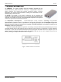
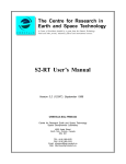
1-3 EQUIPMENT DESCRIPTION:
Aeroflex/Weinschel’s Model 8210A-2-5 SmartStep Programmable
Attenuator/Switch Controller (Figure 1) is designed to interface with Weinschel’s line of SmartStep programmable
attenuators and represents a new concept in device control applications for bench test and subsystem designs. The
8210A-2-5 provides a high-level interface from a standard RS-232/RS-422/RS485 communications interface to the
SmartStep’s serial Driver Interface Bus.
The Device Interface Bus (DIB) is a system for connecting a number of relatively low-speed I/O devices to a host,
providing a simple, uniform, and inexpensive way to control a variety of devices via a single port. The DIB is based on
the two-wire I2C serial bus and several software protocol layers that allow the Model 8210A-2-5 to address up to 125
peripheral devices, with serial data rates of up to 100 KHz. The DIB may also be used to supply DC power to the
devices, resulting in a simple, low-cost interconnection system.
Figure 1. Model 8210A-2-5 Front Panel
Aeroflex / Weinschel
4
Model 8210A-2-5
IM-377
1-4. UNPACKING AND INSPECTION: Upon unpacking the equipment, retain the shipping container and packing
material for future shipment for recalibration. Perform the following initial inspection:
a. Carefully look at the outside of the shipping container for discoloration, stains, charring, or other signs of
exposure to excessive heat, moisture, or liquid chemicals. Check for any physical damage to the shipping
container such as dents, snags, rips, crushed sections or areas, or similar signs of excessive shock or
careless handling.
b. With the equipment and any accessory package removed from the shipping container, check each item
against the packing list or Items Supplied List. If any items are missing, contact the Weinschel Corporation
Customer Service Department.
c.
Carefully inspect the equipment looking for dents, deep scratches, damaged or loose connector, or any other
d. signs of physical abuse or careless handling. If damage is found, forward an immediate request to the
delivering carrier to perform an inspection and prepare a concealed-damage report. DO NOT destroy any
packing material until it has been examined by an agent of the carrier. Concurrently, report the nature and
extent of damage to Weinschel Corporation, giving equipment model and serial numbers, so that necessary
action can be taken. Under U.S. shipping regulations, damage claims must be collected by the consignee;
DO NOT return the equipment to Aeroflex/Weinschel until a claim for damages has been established.
1-5. RESHIPMENT: Use the best packaging materials available to protect the unit during storage or reshipment.
When possible, use the original packing container and cushioning material. If the original packing materials are not
available, use the following procedure:
a. Wrap the storage cases in sturdy paper or plastic;
b. Place the wrapped storage cases in a strong shipping container and place a layer of shock-absorbing material
(3/4 inch minimum thickness) around all sides of the unit to provide a firm cushion and to prevent movement
inside the container.
c.
If shipping the unit for service, attach a tag to indicate:
1.
2.
3.
4.
5.
6.
model and serial numbers
service required
description of malfunction
return address
authorization to conduct repairs
return authorization number
d. Thoroughly seal the shipping container and mark it FRAGILE. Ship to:
Aeroflex / Weinschel, Inc.
Attn: Customer Service Department
5305 Spectrum Drive
Frederick, MD 21703-7362
or to an authorized sales representative.
1-6. STORAGE: Storage of the Model 8210A-2-5 SmartStep™ Programmable Attenuator/Switch Controller is
possible for extended periods without incurring damage to internal circuitry if the 8210A-2-5 Series is packaged
according to the instructions above. The safe limits for storage environment are as follows:
Temperature:
Humidity:
Altitude:
Aeroflex / Weinschel
67° to +167 °F (-55° to +75 °C)
less than 95% without condensation
Up to 40,000 feet
5
Model 8210A-2-5
IM-377
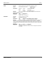
1-7. RELATED MANUALS: The following manuals contain information that may be used in conjunction with this
manual to operate, service, or calibrate this instrument.
Manual
Title
H4-1 and H4-2
Federal Supply Code for Manufacturers Cataloging Handbook
1-8. ELECTROSTATIC DISCHARGE SENSITIVE: The equipment documented in this manual contains certain
Electrostatic Discharge Sensitive (ESDS) components or parts. Therefore, certain procedures/steps are identified by
the use of the symbol .
. This symbol is used in two ways:
CAUTION
All procedures and/or steps identified as must be followed exactly as written and according to
accepted ESDS device handling procedures. Failure to comply WILL RESULT in ESDS damage.
a. When the ESDS symbol is placed between a paragraph number and title
, all of that
paragraph, including all subparagraphs, is considered ESDS device handling procedure.
b. When the ESDS symbol is placed between a procedure/step number and the text
that procedure is considered an ESDS device handling procedure.
, all of
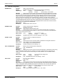
1-9. ABBREVIATIONS AND ACRONYMS: The following list contains abbreviations used throughout this manual.
Abbreviations and acronyms that are not listed conform to MIL-STD-12D.
DUT
ESDS
DIB
TBD
Device Under Test
Electrostatic Discharge Sensitive
Device Interface Bus
To Be Determined
1-10. SAFETY CONSIDERATIONS: The Model 8210A-2-5 Programmable Attenuator/Switch Controller and all
related documentation must be reviewed for familiarization with safety markings and procedures before any operation
and/or service. Refer to the SAFETY SUMMARY located at the beginning of this manual for a summary of safety
information and procedures. Following these simple safety precautions will ensure safe operation and service of the
Attenuator Unit.
1-11. ENVIRONMENTAL REQUIREMENTS: This instrument performs best within its specifications when operated
within a controlled environment having an ambient temperature of 0°± 50°C, Relative Humidity of up to 95% non
condensing, and a altitude of less than 40,000 feet. Operating beyond these limits can affect the accuracy and
performance of the instrument and damage internal circuitry.
Aeroflex / Weinschel
6
Model 8210A-2-5
IM-377
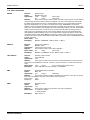
2. SPECIFICATIONS:
2.5mm barrel style
+5 Vdc @ 375 mA
DC Input
Connector:
Requirements:
Driver Interface
Connector:
Environmental
Operating Temperature:
Storage Temperature:
Humidity:
Altitude:
RS-232 Bus(1)
Connector:
Signals:
Baud Rates:
Data Bits:
Handshaking:
Parity:
Indicators:
9-pin male D
TXD, RXD, RTS, CTS, DTR, GND
2400, 9600, 19200, and 38400
8
None, RTS/CTS, XON/XOFF
None, Odd, Even
Tx (Transmit) and Rx (Receive)
Connector:
Signals:
Baud Rates:
Data Bits:
Handshaking:
Parity:
Indicators:
9-pin male D
TXD+, TDX-, RXD+, RTX-, RTS+, RTS-, CTS+, CTS
2400, 9600, 19200, and 38400
8
None, RTS/CTS, XON/XOFF
None, Odd, Even
Tx (Transmit) and Rx (Receive Active)
RS-422 Bus (2) &
RS-485 Bus(3)
14-pin 0.025" square post header @ 0.1"
centers. Mates with AMP 746285-2 or equivalent.
Signals :
SDA
serial data
SDC
serial clock
VDC
DC supply voltage
GND
ground
VDC Output current:
2 A maximum
Maximum cable length: 10 Meters (1000 pF maximum capacitance)
Data Transfer Rate:
100 KHz
0 to +50°C
67° to +167 °F (-55° to +75°C)
95%
40,000’ (12,192M)
NOTES:
1.
2.
3.
RS-232 can be used with standard PC serial port for short and medium distances (up to approximately 50 ft).
RS-422, designed for very long distance communications (4000 ft) & optimized as a single node protocol, typically with one device
connected to a single port.
RS-485, designed for very long distance communications (4000 ft) & optimized for multi-drop connections that can used to
create a low cost network.
Aeroflex / Weinschel
7
Model 8210A-2-5
IM-377
3. PHYSICAL DIMENSIONS:
Note: All dimensions are given in mm (inches) and are maximum, unless specified.
Aeroflex / Weinschel
8
Model 8210A-2-5
IM-377
4. INSTALLATION:
4-1. MOUNTING: Each SmartStep Interface is supplied with four 4-40 UNC-2B mounting holes located on bottom
side of the housing. Screw penetration into housing is 3/16" maximum. See paragraph 3 for mounting location.
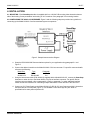
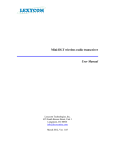
4-2 CONFIGURING THE 8210A-2-5 HARDWARE: Figure 2 and the following steps are provided as a guideline in
connecting up the Model 8210A-2-5 and its associated system components.
Figure 2. Sample Interconnection Diagram
a. Setup the RS-232/422/485 Communications options for your application using paragraph 5-1 and
Figure 3.
b. Connect the desired controller to the Model 8210A-2-5-X’s bus connector. For specific connector details
reference the following:
Model Bus
8210A-2-5-2
8210A-2-5-2
c.
Type
RS-232
RS-422/485
Paragraph
5-3
5-4
Using the interconnect cable (P/N 193-8013) supplied with the Model 8210A-2-5, connect the SmartStep
Attenuator or other device to the Model 8210A-2-5’s Driver Interface connector. For specific Device
Interface connector details, refer to paragraph 6-2. Refer to paragraph 7 to order additional interface
cables and other accessories for connecting multiple attenuators or other devices to the 8210A-2-5.
d. Connect a +5 V Power Supply to the Model 8210A-2-5’s DC IN +5V Input Connector which is located on
the Model 8210A-2-5 front panel (Figure 1), is a standard 2.5mm barrel style DC jack. Refer to
specifications for exact power requirements.
Aeroflex / Weinschel
9
Model 8210A-2-5
IM-377
5. SERIAL (RS-232, RS-232 & RS-485) OPERATION:
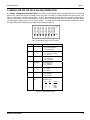
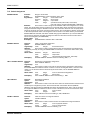
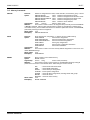
5-1. SERIAL COMMUNICATIONS SETTINGS: The Serial Communications options are programmed via an internal 8
position DIP switch SW1 which is located on the rear panel. The switch is shared between the two functions, with
SW1-1 controlling the selection. When SW1-1 is OFF, the remaining switches are used fro other configurations.
Likewise, when SW1-1 is ON, the switches are used to select the various serial options, including baud rate, parity,
and handshaking. Refer to Figure 4 for switch location. To configure the serial communications parameters, select
the appropriate switch setting using the table located in below (Figure 3).
SW1
Serial
Serial Parameters
1
SP
Mode Select
On = Serial parameters
Off = GPIB address
2
Echo
Echo Echo Enable
On = Echo received data
Off = No echo
3
HndshkSel
Handshaking Select
On = RTS/CTS
Off = XON/XOFF
4
HndshkEna
Handshake Enable
On = Enabled
Off = Disabled
5
ParitySel
Parity Select
On = Odd
Off = Even
6
ParityEna
Parity Enable
On = Enabled
Off = Disabled
7
8
BR1
BR2
BaudRate Select (see below)
BaudRate Select
BR1
BR0
RATE
0
0
1
1
0
1
0
1
2400
9600
19200
38400
Figure 3. Internal Dip Switch
Aeroflex / Weinschel
10
Model 8210A-2-5
IM-377
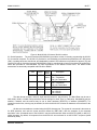
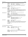
Figure 4. Model 8210A-2-5 Internal Switch Locations
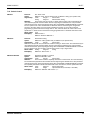
6-2. Serial Operation. The serial interface (RS232/RS422) provides a means of remotely programming the 8210A2-5 via external computer. The 8210A-2-5 provides for user-selectable communications parameters via a DIP switch
(SW1), including baud rate, data format, and handshaking method. LED indicators are provided for transmit (TX) and
receive (RX) activity. Selection between RS232/RS422 mode is controlled via an internal 4 position DIP switch SW2,
which also provides for user-selectable 120 ohm terminations for the RS422 receiver lines. The RS422 mode
transceivers are electrically compatible with RS-422 or RS485.
SW2
RS232
RS422
RS485
User
Select
1
OFF
2
OFF
User
Select
3
4
OFF
ON
ON
OFF
Description
CTS Termination
On = Termination
Off = No Termination
RXD Termination
On = Termination
Off = No Termination
RI/RTS Select
Serial Mode
On = RS232
Off = RS422
The data format includes a start bit, eight data bits, and one stop bit (N81). The Baud Rate may be set to
2400, 9600, 19200, or 34800. Parity selections include settings for None, Even, or Odd parity. Handshaking may be
enabled, if desired, and the method may be set to either hardware (RTS/CTS) or software (XON/XOFF). For
interactive terminal use, echoing may be enabled, in which the 8210A-2-5 will echo all characters received back to the
terminal.
All data and commands are encoded using the ASCII character set. The syntax for commands is the same as
for GPIB operation, and uses the syntax structure defined by IEEE 488.2, with the exception of the command
termination rules. Commands sent to the 8210A-2-5 may be terminated with either an ASCII CR (0x0D) or ASCII LF
(0x0A) character. By default, all responses from the 8210A-2-5 are terminated in an ASCII CR/LF sequence (0x0D
followed by 0x0A).
Aeroflex / Weinschel
11
Model 8210A-2-5
IM-377
Software handshaking uses the XON/XOFF scheme in which an ASCII DC3 (0x13) character is transmitted
by the receiver to indicate that data transmission should be halted (XOFF), and an ASCII DC1 (0x11) character is
transmitted to indicate that data transmission may continue (XON). Hardware handshaking utilizes the RTS and CTS
lines. When the RTS output signal is asserted true, the unit is ready for data. This signal should be connected to the
external computer's CTS input signal, so that when the receiver is ready, the transmitter may send data. When the
unit is not ready for data, it unasserts the RTS signal, halting data transmission. Likewise, the unit monitors the CTS
input signal during data transmission, halting transmission if the external computer unasserts it's RTS signal. In
addition, the 8210A-2-5 unasserts the RTS signal while command execution is in progress.
For those systems incorporating local front panel controls, the serial port can lockout local users, providing a Remote/
Local function similar to that of GPIB operation.
Aeroflex / Weinschel
12
Model 8210A-2-5
IM-377
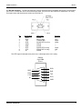
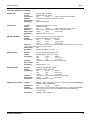
5-3. RS-232 Operation: The RS-232 Serial port is a 9-pin connector that is compatible with the pin-out of the serial
port on a PC. It allows the use of a null-modem style cable. The pin-out for the connector is show below. For clarity,
the signal names and directions are relative to the 8210A-2-5.
Pin
1
2
3
4
5
6
7
8
9
Signal Name
DCD
RxD
TxD
DTR
GND
DSR
RTS
CTS
RI
Description
unused
Receive data
Transmit data
Signals DTE is on-line
Ground
unused
Signals DTE is ready
Signals DCE is ready
unused
Direction
--input
output
output
----output
input
---
The DTR signal is asserted when power is on, indicating that the unit is ready.
RS232
9-pin DB9
Pinout
DSR
RTS
CTS
RI
Aeroflex / Weinschel
6
7
8
9
1
2
3
4
5
DCD
RxD
TxD
DTR
GND
13
Model 8210A-2-5
IM-377
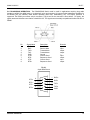
5-4. RS-422/RS485 OPERATION: The RS422/RS485 Serial mode is useful in applications requiring long cable
lengths (up to5000 ft at 9600 baud), or in electrically noisy environments. All communication parameters available for
the RS232 port are available under RS422 operation (baud rate, handshaking, etc). Full Duplex operation is
supported. The RS422 port utilizes a 9-pin connector. The pin-out for the connector is show below. For clarity, the
signal names and directions are relative to the8210A-2-5. The signals are electrically compatible with either RS-422 or
RS485.
Pin
1
2
3
4
5
6
7
8
9
Signal Name
RxD+
RxDTxD+
TxDGND
CTS+
RTSCTSRTS+
Description
Receive data
Receive data
Transmit data
Transmit data
Ground
Clear to Send
Request to Send
Clear to Send
Request to Send
Direction
input
input
output
output
--input
output
input
output
RS422
9-pin DB9 Pinout
CTS+
RTS CTS RTS+
Aeroflex / Weinschel
6
7
8
9
1
2
3
4
5
RXD+
RXDTXDTXD+
GND
14
Model 8210A-2-5
IM-377
6. DEVICE INTERFACE BUS (DIB) OPERATION
6-1. GENERAL OPERATION: The Device Interface Bus is a serial bus that includes a physical layer based on the
two-wire I2C serial bus developed by Philips, and several software layers. The software layers are based on the
ACCESS.Bus protocols V2.2, and include a base protocol, and several specific device protocols, along with specific
Weinschel extensions to control RF devices.
The base protocol defines standard messages for device communication, device initialization, device
identifications, address assignment, and a message protocol for device reports and control information.
The DIB is based on two wires, serial data (SDA) and serial clock (SCL), which carry information between the
devices connected to the bus. Following initialization, each device is recognized by a unique address and can operate
as either a master transmitter or slave receiver. A master is the device which initiates a data transfer on the bus and
generates the clock signals to permit that transfer. The master device always transmits data to the slave. Any device
addressed by the master is considered a slave. The DIB is a multi-master bus. Every device connected to the DIB is
capable of being both a bus master and a bus slave.
Both SDA and SCL are bi-directional lines, connected to a positive supply voltage via a current source or pullup resistor. When the bus is free, both lines are HIGH. The output stages of devices connected to the bus have an
open-drain or open collector in order to perform a wired-AND function. Data on the I2C bus can be transferred at a
rate up to 100 kbit/s. The number of device interfaces connected to the bus is dependent on the bus capacitance limit
of 1000 pF, the overall bus length of 10 meters, and the current available to power the devices.
The protocol of the messaging system used by the 8210A-2-5 uses available length format with five fields,
including the destination address, source address, message length, 0 to 127 data bytes, and a checksum.
Device Identification on the bus is provided by a unique 28-byte sequence that provides the protocol revision,
vendor, module revision, 8 character module name, and a 32-bit device id. For most devices, this device id is the
serial number of the device, however, a non-serialized device may generate a random negative 32-bit number for use
as an id. Device Capabilities is a set of information that describes the functional characteristics of the device, along
with the proper API (Applications Programming Interface) to use in communicating with the device. The purpose of
capabilities information is to allow the 8210A-2-5 to recognize and use the features of devices without prior knowledge
of their particular implementation. Capabilities information provides a level of device independence and modularity.
For example, consider two different types of attenuation devices, a step attenuator and a pin-diode attenuator. While
each device has its’ own unique set of characteristics, they both are capable of setting an attenuation value. By similar
devices providing a consistent API to the 8210A-2-5, the user is freed from the concerns of the low-level programming
required to control each device.
Aeroflex / Weinschel
15
Model 8210A-2-5
IM-377
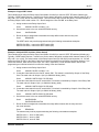
6-2. DIB CONNECTOR. This connector (shown below) is a 14-pin 0.025" square post header @ 0.1" centers and is
located on the front panel of the Model 8210A-2-5 and mates with AMP connector P/N 746285-2 or equivalent.
Name
Pin
VIN
GND
D0/SDA
D1/SCL
GND
1, 2
3, 4
7
8
5, 6
11, 12
9, 10
13
14
/I2C
/RST
Aeroflex / Weinschel
Description
dc Supply Voltage, +5 V
dc Return
SDA
SCL
GND
Mode Select Output
Output
16
Model 8210A-2-5
IM-377
7. CONFIGURING & USING THE 8210A-2-5
7-1. MANUFACTURING SELECT SWITCH SW3:
NOTE: DO NOT change these switches from the default setting sunless instructed to do so by the factory. This
information is provided for reference only (Figure 5 shows the location of this switch).
SW3
Description
1
UCS
On = Enabled (Default)
Off = Disabled
2
MCS
On = Enabled
Off = Disabled (Default)
3
NMI Disable
On = Enabled (Default)
Off = Disabled
4
Flash Monitor
On = Enabled
Off = Disabled (Default)
7-2. CONFIGURATION FUNDAMENTALS: The configuration process is used to detect the devices that are present
on the bus, assign each device a unique address, and connect devices to the appropriate software protocol. When
reset or powered-up, all devices always revert to a default address of110 (0x6E). To begin address assignment, the
8210A-2-5 host which resides at address 0x50, sends an Identification Request message to the default address.
Every device at this address then responds with an Identification Reply message. As each device sends its message,
the arbitration mechanism automatically separates the messages based on the identification strings. The 8210A-2-5
can then assign an address to each device by including the matching identification string in an Assign Address
message. A device that receives this message and finds a complete match with the identification string moves its
device address to the new assigned value. After assigning a unique address to a device, 8210A-2-5 retrieves the
device’s Capabilities string. The 8210A-2-5 then parses this Capabilities string to choose the appropriate application
protocol for the device. During this configuration process, the front panel LED’s flash at a rapid rate. When completed,
the LED’s will extinguish, unless a configuration discrepancy is encountered, in which case they will remain
illuminated.
As can be seen from the above discussion, the assignment of addresses to devices during the configuration
phase is totally arbitrary, and will most probably change each time the configuration process is performed. This
presents us with the following problem, especially for systems containing multiple devices...how does one send
commands to a particular device? One method is by requesting a list of all the configured devices and scanning the
list to find the device model, id, and address information. The 8210A-2-5 provides a much simpler and easier method
- assigning a name to a device. The 8210A-2-5 allows the user to assign an alphanumeric name of up to 10
characters in length to a device, and can store this association in it’s non-volatile EEPROM memory for future use. As
part of the power-up configuration process, the 8210A-2-5 will automatically recall and assign these names to the
appropriate devices. This one-time setup process can greatly simplify the users software, as certain high-level
commands require the use of a device name as one of the command parameters.
7-3. DEVICE PROTOCOLS. All devices connected to the 8210A-2-5 understand a core set of commands, referred
to as the Base Protocol, which is used in the basic transfer of commands and data. In addition to this base set of
commands, different device types require their own unique set of commands, or protocol, in order to function. For
example, an attenuation device would be expected to have a different programming model than say, a switch
controller. On the other hand, devices may be similar in nature, with only slight differences in their command sets.
The 8210A-2-5 architecture allows protocols to be structured in a hierarchical or tree fashion where protocols may
build on the capabilities of parent protocols, inheriting the functionality of the parent.
Aeroflex / Weinschel
17
Model 8210A-2-5
IM-377
Currently, there are four protocols. These are the Base, Attn, StepAttn, and Switch protocols. They are
arranged as follows:
Base Protocol
Attn Protocol
StepAttn Protocol
Switch Protocol
Devices that support the Attn Protocol also include support for the Base Protocol. Such a device does not,
however, include support for the StepAttn Protocol, and would not be able to execute commands supported by this
protocol. On the other hand, a device supporting the StepAttn Protocol includes support forall protocols above it,
including both the Attn Protocol and the Base Protocol. The 8210A-2-5 assigns a protocol to a device based on
information returned by the device during the configuration process. This protocol selection allows the 8210A-2-5 to
determine the appropriate set of commands for use in controlling the device.
To illustrate the usage of these protocols, let’s consider an example. In reviewing the command set, one finds
that the Attn Protocol supports a command for setting the attenuation value ofa device, in dB. The Weinschel
SmartStep series of attenuators utilize the StepAttn Protocol. Since the StepAttn protocol is derived from the Attn
protocol, the SmartStep attenuators inherit the use of this command. The command syntax and functionality is the
same, whether programming the Attn or the StepAttn protocol. This brings us to our next topic.
7-4. THE VIRTUAL ATTENUATOR. Sometimes, when constructing a system or subsystem, you cannot find a
device that provides quite the functionality that you require. Assume you need a large attenuation range, but a small
incremental step size. Typically, one would be forced to use two physical attenuators connected in series to achieve
this goal. For example, let’s assume there is a requirement for an attenuator with a total attenuation > 80dB, with a
resolution of 1 dB over the DC-18 GHz frequency range. One could combine a Model 150T-70 (0-70dB/10dB steps)
with a Model 150T-11 (0-11dB/1dB steps) to meet this goal. Unfortunately, the programming burden has increased
dramatically, since you must now not only write the software to control two separate devices, but also develop an
algorithm for determining the appropriate settings for each device. In addition, if your requirements were to change
perhaps a larger attenuation range, or a different step size, these algorithms would have to change accordingly. The
8210A-2-5 provides a solution to this dilemma with the ability to create and define a virtual device. A virtual device
allows the user to construct a device by combining the attributes of several physical devices, and be able to program
this combination as if it were one physical device! Revisiting our example above, we can create a virtual attenuator
with an attenuation range of 81dB/1dBsteps, effectively creating a "150T-81". Controlling this new device requires no
more programming than controlling a single attenuator.
The 8210A-2-5 currently supports up to 32 Virtual Attenuator devices, each of which allow up to four physical
attenuators to be combined into a single "device". The Virtual Attenuator uses the Attn Protocol command set,
providing the same programming interface as other attenuator devices. During the setup process, the user assigns a
name to the virtual attenuator, which may be stored in the 8210A-2-5’s non-volatile EEPROM memory for future use.
During the power-up configuration process, the 8210A-2-5 will automatically recall and assign these virtual devices.
7-5. ATTENUATOR GROUPS. Attenuator groups provide the ability to associate a list of multiple attenuators (either
physical or virtual) with a single group name, and allow commands to be executed across all the attenuators in the
group. For example, let’s assume that a portion of a system contains 8 attenuators, and you wish to increment the
attenuation value of each of the eight attenuators. You could send eight separate INCR commands, one to each of the
attenuators. An easier, and faster, method would be to combine the eight attenuators into a group, and then send a
single INCR command to the group. Groups are a convenient method of reducing program complexity, and can
radically reduce communication overheads. In the example above, the eight separate INCR commands would have
required approximately 104 characters to be transmitted. If serial communications were being used with a baud rate of
9600, this would require a minimum of 108 msec just for the character transmissions. In contrast, the single group
INCR command would have only required 8 characters, resulting in over a 12 times increase in throughput! With a few
exceptions, most of the frequently used commands that apply to attenuators may also be used on groups, including
ATTN, RELATTN, REF,STEPSIZE, INCR, and DECR.
Aeroflex / Weinschel
18
Model 8210A-2-5
IM-377
The 8210A-2-5 currently supports up to 4 attenuator groups, each of which allow up to 32 physical or virtual
attenuators. During the setup process, the user assigns a name to the group, and lists the attenuators that comprise
the group, which may be stored in the8210A-2-5’s non-volatile EEPROM memory for future use. During the power-up
configuration process, the 8210A-2-5 will automatically recall and assign these group associations.
7-6. THE VIRTUAL SWITCH. The Virtual Switch capabilities allow the user a convenient method of controlling
devices such as RF switches by specifying the switch control line connections and operational mode via the193-8015
8-Channel Relay Output card. Outputs from the card may be divided into logical groups of from one to eight control
signals. Each group is assigned a user-definable name, and maybe controlled separately from the other groups. This
would allow the user to connect, say 8 SPDT RF switches to the Relay Output card, and control each switch
independently without having to keep track of each switch’s individual position. Another feature, which is useful for
multi-line control applications, is the ability to specify whether the control signals in the group operate in an encoded
or decoded fashion. For example, a SP3T switch typically requires 3 individual control signals, only one of which may
be active at a time. These three control signals provide up to8 different programming codes from 000b to 111b, many
of which are actually invalid settings in this application. By operating in Decoded mode, the virtual switch will only
activate one output at a time, allowing the user to specify position 1, 2, or3 when programming.
The 8210A-2-5 supports up to 32 Virtual Switch devices, each of which can support up to a maximum of 16
output signals. The Virtual Switch uses the Switch Protocol command set. During the setup process, the user assigns
a name to the virtual switch, which may be stored in the 8210A-2-5’s non-volatile EEPROM memory for future use.
During the power-up configuration process, the8210A-2-5 will automatically recall and assign these virtual devices.
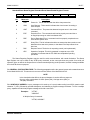
7-7. STATUS REPORTING.
The 8210 implements the 488.2 Status Reporting Structure, which utilizes the
IEEE488.1 status byte with additional data structures and rules. The Status Byte Register can be read with either a
serial poll (IEEE-488 operation only) or the *STB? common query command. The Service Request Enable Register
allows the user to select which bits in the Status Byte Register may cause service requests. A bit value of one
indicates that the corresponding event is enabled, while a bit value of zero disables an event. The Service Request
Enable Register may be accessed with the *SRE and *SRE? common commands. The Status Byte Register may be
cleared with the *CLS common command, with the exception of the MAV bit, which is controlled by the operation of
the Output Queue.
Status Byte Register/ Service Request Enable Register Formats
D7
D6
RQS
D5
ESB
D4
MAV
D3
D2
D1
D0
Bit
Mnemonic
6
RQS
Request Service: This bit, if set, indicates that the device is asserting the
SRQ signal.
5
ESB
Event Status Bit: This bit is true when an enabled event in the Event Status
Register is true.
4
MAV
Message Available: This bit is true when there is valid data available in the
output queue.
Description
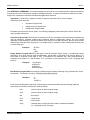
The Standard Event Status Register is used to report various IEEE488.2-defined events. The register
contents may be accessed with the *ESR? command. An Event Status Enable Register allows the user to select
which bits in the ESR that will be reflected in the ESB summary message bit of the Status Byte Register. The Event
Status Enable Register may be accessed with the *ESE and*ESE? common commands. The Event Status Register is
cleared by an *ESR? query or *CLS common command.
Aeroflex / Weinschel
19
Model 8210A-2-5
IM-377
Standard Event Status Register/ Standard Event Status Enable Register Formats
D7
ON
D6
URQ
D5
CME
D4
EXE
D3
DDE
D2
QYE
D1
RQC
D0
OPC
Bit
Mnemonic
Description
7
PON
Power On: This bit indicates that the device has powered-on
6
URQ
User Request: This event bit indicates that a local control is causing a
User Request
5
CME
Command Error: The parser has detected a syntax error in the current
command.
4
EXE
Execution Error: The command could not be properly executed due to
an illegal input range or other inconsistent data.
3
DDE
Device Dependent Error: A command could not properly complete due to
some device specific error
2
QYE
Query Error: This bit indicates that either an attempt has been made to read
data when there was none present, or that data in the Output Queue has
been lost
1
RQC
Request Control: The device is requesting control (not implemented)
0
OPC
Operation Complete: This bit is generated in response to an *OPC
command. It indicates that the ITS 2000 has completed all pending
operations.
The Status Reporting Registers may be used for serial communications, with certain limitations. The Status
Byte Register can only be read via the *STB? query command, as the comm port does not provide for a serial poll
operation. Also, as data in the Output Queue is sent automatically during serial operation, the MAV message available
bit in the STB serves no purpose.
7-8. GENERAL SYNTAX STRUCTURE: The following paragraphs outline the general syntax and command structure
for the Model 8210A-2-5. This structure is common to all bus flavors of the Model 8210A-2-5.
NOTE
In the descriptions that follow, the term whitespace is used to define a sequence
of one or more combinations of ASCII Space (20h), Carriage return (0Dh), or
Tab (09h) characters.
7-8.1 SYNTAX OF QUERIES: A query message unit is made up of a query header ending in an ASCII question mark
character ’?’ (3FH), followed by optional whitespace, and ended by a program message terminator. To form a multiple
query, separate the individual program message units with a semicolon.
Examples :
"ATTN?"
"ASSIGN?"
b. Multiple Query Commands:
"ATTN?; ASSIGN?"
Aeroflex / Weinschel
20
Model 8210A-2-5
IM-377
7-8.2 SYNTAX OF COMMANDS: A command message unit is made up of a command header, optionally followed by
an argument and units, and ended by a program message terminator. If multiple commands are made on the same
program line, separate the individual command messages with a semicolon.
Arguments - The 8210A-2-5 supports a variety of argument types that can be used in program
commands. These types are:
Character Program Data
Integer Numeric Program Data
Real Numeric Program Data
Each data type has its own rules of syntax. The following paragraphs provide the syntax rules for each of the
argument types listed above.
Character Program Data-This data type is comprised of the set of printable ASCII characters (excluding those
used as delimiters). Character program data represents alpha or alphanumeric strings. The use of alpha
characters is case-insensitive. If the first character of the string is not an alpha character, then the string must be
delimited with either the ASCII single-quote (’) or double-quote (") character in order to distinguish the string from
a numeric data type.
Examples:
ATTEN1
ON
"150T"
Integer Numeric Program Data-This data type is used to represent integer, binary, or hexidecimal numeric
information, all of which may be used interchangeably. Integer data is comprised of the numeric digits ’0’-’9’,
binary data is comprised of the digits ’0’ and ’1’ preceded by the characters ’#B’, and hexidecimal data is
comprised of the digits ’0’-’9’, and the letters ’A’-’F’, preceded by the characters ’#H’ or the C language style
prefix ’0x’.
Examples:
123 (integer)
#H55 (hex)
0xAA (hex)
#B1010 (binary)
Real Numeric Program Data-This data type includes decimal numbers containing a sign, decimal point, and/or
an exponent. The format is as follows: [sign]digits[.[digits][E[sign]digits]]
Examples:
2
2.5
-35.25E+2
In the command descriptions that follow, argument types are also described using the following additional
conventions to indicate the relative size of the parameter:
byte
- used to indicate an 8-bit unsigned integer
word
- used to indicate a 16-bit unsigned integer
int8
- 8-bit integer
int16
- 16-bit integer
int32
- 32-bit integer
string
- character data, including the max number of characters allowable.
(i.e., string8 has a max of 8 chars)
Aeroflex / Weinschel
21
Model 8210A-2-5
IM-377
7-8.3 OUTPUT DATA FORMAT. Output data from the Model 8210A-2-5 consists of a series of ASCII digits and
message strings, terminated with an ASCII Line-Feed character (0AH), in response to a program message that
contains one or more query commands. In the case of multiple query commands in the same program message, the
data resulting from each of the individual message units will be separated by an ASCII comma (2CH) character.
7-8.4 NOTATIONAL CONVENTION.
[]
Brackets indicate optional arguments or parameters.
{}
One and only one of the enclosed entries must be selected unless the field is also
surrounded by brackets, in which case it is optional.
...
Ellipses indicate that the preceding argument or parameter may be repeated.
[,...]
The preceding item may be repeated, but each repetition must be separated by a comma.
Aeroflex / Weinschel
22
Model 8210A-2-5
IM-377
7-9. 488.2 COMMON COMMANDS
*CLS
Function:
Syntax:
Argument(s):
Remarks:
Return Value:
Example(s):
Clears the Status Byte and Event Status Registers.
*CLS
none
This function is used to clear the Status Byte and the Event Status Registers.
none
*CLS
*ESE
Function:
Syntax:
Argument(s):
Remarks:
Return Value:
Example(s):
Sets the Event Status Enable Register.
*ESE mask
mask integer bitmask
This function is used to set the Event Status Enable Register to the value specified by mask.
none
*ESE 255
*ESE?
Function:
Syntax:
Argument(s):
Remarks:
Return Value:
Example(s):
Reads the Event Status Enable Register.
*ESE?
none
This function is used to read the Event Status Enable Register.
mask integer register mask
*ESE? returns the following ’255’
*ESR?
Function:
Syntax:
Argument(s):
Remarks:
Return Value:
Example(s):
Reads the Event Status Register
*ESR?
none
This function is used to read the Event Status Register. Reading the register clears it.
reg integer register
*ESR? returns the following ’128’
*SRE
Function:
Syntax:
Argument(s):
Remarks:
Return Value:
Example(s):
Sets the Status Byte Enable Register
*SRE mask
mask integer bitmask
This function is used to set the Status Byte Enable Register to the value specified by mask.
none
*SRE 255
*SRE?
Function:
Syntax:
Argument(s):
Remarks:
Return Value:
Example(s):
Reads the Status Byte Enable Register.
*SRE?
none
This function is used to read the Status Byte Enable Register.
mask integer register mask
*SRE? returns the following ’255’
*STB?
Function:
Syntax:
Argument(s):
Remarks:
Return Value:
Example(s):
Reads the Status Byte Register.
*STB?
none
This function is used to read the Status Byte Register.
reg integer register
*STB? returns the following ’96’
*IDN?
Function:
Syntax:
Argument(s):
Remarks:
Reads the system identification information.
*IDN?
none
This function is used to read the system identification information, which is a string consisting of the
following data: manufacturer, model, serial number, and firmware version.
mfg integer count of devices
*IDN? returns the following ’Weinschel,8210A-2-5 Series, 123, 1.00A’
Return Value:
Example(s):
Aeroflex / Weinschel
23
Model 8210A-2-5
IM-377
*RST
Function:
Syntax:
Argument(s):
Remarks:
Return Value:
Example(s):
Performs a device reset.
*RST
none
This function is used to reset the device.
none
*RST
*OPC
Function:
Syntax:
Argument(s):
Remarks:
Operation complete service request.
*OPC
none
This function generates the Operation Complete message (OPC) in the Standard Event Status
Register when all pending device operations have finished.
none
*OPC
Return Value:
Example(s):
Return Value:
Example(s):
Operation complete query
*OPC?
none
This function loads a ’1’ into the output queue when the Program Message Unit is executed. Its
primary use is to provide an indication of command completion by including the command as the
last one in a series of commands.
1 integer command completed
SAVE ASSIGN; *OPC? returns a ’1’ when the SAVE ASSIGN command completes.
*WAI
Function:
Syntax:
Argument(s):
Remarks:
there
not
Return Value:
Example(s):
Wait To Continue
*WAI
none
This function prevents the8210A-2-5 Series from executing any further commands or queries until
are no pending operations. The8210A-2-5 Series executes all commands sequentially, and does
allow overlapping commands.
none
*WAI
*TST?
Function:
Self-test query
Syntax:
*TST?
Argument(s): none
Remarks:
This function performs an internal self-test. Upon completion, the results of the test are loaded into
the output queue.
Return Value:
testresultsinteger’0’ indicates test passed. Non-zero indicates test failed.
Example(s):
*TST? returns a ’0’ when the test completes successfully.
*OPC?
Function:
Syntax:
Argument(s):
Remarks:
Aeroflex / Weinschel
24
Model 8210A-2-5
7-10.
IM-377
Device Assignment & Configuration Commands
ASSIGN?
Function:
Syntax:
Argument(s):
Assign a name to a physical device
ASSIGN name model serialno
name
string10
device name
model
string8
device model
serialno
int16
device serial number
Remarks:
This function is used to assign a user-definable name to a physical device. The device is
identified by the model and serialno parameters, which may be obtained by using the LIST? DEVICE
CONFIG command to see a list of the configured devices. Assigning a name to a device allows the user to
refer to the device by name, instead of by address. The configuration process, upon detection of a device
matching the model and serialno, will automatically associate the name with the device. Specifying a
serialno of -1 will allow the 8210A-2-5 to match any device of the appropriate model, however, use this
feature with caution, since a system containing multiple instances of the same model will fail to configure
appropriately. The assignment can be stored in non-volatile memory via the SAVE ASSIGN command, and
will be recalled during system initialization. Up to 125 user-definable names may be assigned. Note that the
assignment does not take effect until the next time device names are reassigned (see REASSIGN).
Return Value: none
Example(s):
ASSIGN AT1 ’150T-70’ 103
ASSIGN?
Function:
reads a device name assignment
Syntax:
ASSIGN? name
Argument(s): name
string10
device name
Remarks:
This function is used to read the device model and serialno parameters associated with an
assignment previously set using the ASSIGN command.
Return Value: name
string10
device name
model
string8
device model
serialno
int16
device serial number
Example(s):
ASSIGN? AT1 returns the following ’AT1, 150T-70, 103’
LIST? ASSIGN
Function:
Reads a list of device assignments
Syntax:
LIST? ASSIGN
Argument(s): none
Remarks:
This function is used to read a list of all device assignments created using the ASSIGN
command. The list contains a count of the assigned names, and a list of names. To see the actual device
information referenced by each assignment, use the ASSIGN? command.
Return Value: count
integer
count of assignments
name
string10
device name
Example(s):
LIST? ASSIGN returns the fol lowi ng ’4, AT1, AT2, SW1, SW2’
RECONFIG
Function:
Run the system device configuration
Syntax:
RECONFIG
Argument(s): none
Remarks:
This function is used to run the system device configuration process that is performed at
power-on, which can be used to install or remove a device. After the configuration process, then the device
names are assigned (see REASSIGN).
Return Value: none
Example(s):
RECONFIG
RECONFIG?
Function:
Run the system device configuration, and returns results.
Syntax:
RECONFIG?
Argument(s): none
Remarks:
This query function performs the same configuration process as the RECONFIG command,
and then returns a count of the devices installed.
Return Value: count
integer
count of devices successfully configured
Example(s):
RECONFIG? returns the following ’2’ assuming there are two devices
Aeroflex / Weinschel
25
Model 8210A-2-5
IM-377
REASSIGN
Function:
Reassign device names.
Syntax:
REASSIGN
Argument(s):
none
Remarks:
This function is used to reassign changes that may have been made to the
device assignments with the ASSIGN, ASSIGN ATTN, and ASSIGN SWITCH commands. Unlike
the RECONFIG command, it does not perform the physical device configuration process, and
executes much faster.
Return Value:
none
Example(s):
REASSIGN
COUNT? DEVICE
Function:
Syntax:
Argument(s):
Remarks:
Return Value:
Example(s):
LIST? DEVICE
Function:
Read device installation
Syntax:
LIST? DEVICE Argument(s): none
Remarks:
This function is used to read a list of the names of all physical devices that
have been installed by the configuration process. It returns a count of the devices, and for each
the device name.
Return Value:
count
integer
count of names
name
string10
name
Example(s):
LIST? DEVICE
returns the following ’2, SW1, RFSWITCH’
LIST? DEVICE CONFIG
Function:
Syntax:
Reads a list of installed devices
LIST? DEVICE CONFIG
or LIST? DEV CFG
Argument(s):
none
Remarks:
This function is used to read a list of the physical devices that were installed by
the configuration process. The list contains a count of the devices installed, and for each the
device name, model, id, and address. The name returned is the device name assigned via the
ASSIGN command. If the device does not have an assigned name, then the string NONAME is
returned in this field. The model and id fields are read from the device, and the addr field is the
Device Interface Bus address assigned by the 8210A-2-5 configuration process.
Return Value:
count
integer
count of devices
name
string10
device name
model
string8
model
id
integer32
serial number
addr
int8
address
Example(s):
LIST? DEVICE CONFIG
returns the following ’2, AT1, 150T-70, 102,
2, AT2, 150T-11, 113, 4’
CONFIG DEVICE COUNT
Function:
Sets the count of devices for system configuration verification
Syntax:
CONFIG DEVICE COUNT devcnt
Argument(s):
devcnt
integer
count of physical devices
Remarks:
This function is used to set the number of expected devices for the system
configuration process. If during the configuration process at least devcnt number of physical
devices are not found, the configuration process fails. The value can be stored in non-volatile
memory via the SAVE CONFIG command, and will be recalled during system initialization.
Return Value:
none
Example(s):
CONFIG DEVICE COUNT 8
CFG DEV CNT 6
CONFIG? DEVICE COUNT
Function:
reads the system device count configuration
Syntax:
CONFIG? DEVICE COUNT
Argument(s):
none
Remarks:
This function is used to read the number of devices expected during the
system configuration process. Return Value: devcnt integer count of devices
Example(s):
CONFIG? DEVICE COUNT returns the following ’8’
Aeroflex / Weinschel
Reads the number of configured devices
COUNT? DEVICE
none
This function is used to read the number of installed and configured devices.
count integer count of devices
COUNT? DEVICE returns the following ’4’
26
Model 8210A-2-5
IM-377
ADDR?
Reads the Device Interface Bus address assigned to a device.
This command has two forms:
ADDR? devname
ADDR? model id
Argument(s):
devname
string10
assigned device name
or
model
string8
device model
id
integer32
device serial number/id
Remarks:
This function is used to read the address assigned to the specified device
during the configuration process.
Return Value:
addr
integer address
Example(s):
ADDR? AT1 returns ’2’
ADDR? 150T-11 103 returns ’2’
ISPRESENT?
Function:
Syntax:
Argument(s):
Aeroflex / Weinschel
Function:
Syntax:
Checks for presence of a device
ISPRESENT? [type] name
type
optional string literal (DEVICE, ATTN, or SWITCH)
name
string10
device name (physical or virtual)
Remarks:
This function is used to check for the presence of a physical or virtual device. If
the device specified by name is installed and configured, the query returns a ’1’, otherwise it
returns a ’0’. The optional type parameter may be used to qualify a specific type of device. If type
is not specified, then the name will be searched in the list of attenuators, switches, and devices, in
that order.
Return Value:
flag
integer
name found
Example(s):
ISPRESENT? AT1 returns the following ’1’
ISPRESENT? SWITCH AT1 returns a ’0’ if AT1 is assigned to an attenuator,
not a switch
27
Model 8210A-2-5
IM-377
7-11. Attenuator Assignment
ASSIGN ATTN
Function:
Syntax:
Argument(s):
Assign a virtual attenuator
ASSIGN ATTN name devname [devname [devname [devname]]]
name
string10
virtual attenuator name
devname
string10
device name(s). see remarks.
Remarks:
This function is used to assign a user-definable name and configuration to a virtual
attenuator. The virtual attenuator may contain a reference for up to 4 physical devices, each of which
must have been previously assigned a devname using the ASSIGN command. This function allows
multiple attenuators to be logically joined to a single name, allowing the user to create an attenuator
with the combined characteristics of the specified devices, perhaps to provide a larger maximum
attenuation value, or a finer step size, or both. The assignment can be stored in non-volatile memory via
the SAVE ASSIGN ATTN command, and will be recalled during system initialization. Up to 64 userdefinable names may be assigned. Note that the assignment does not take effect until the next time
device names are reassigned (see REASSIGN).
Return Value: none
Example(s):
ASSIGN ATTN Chan1 AT1 AT2
ASSIGN? ATTN
Function:
reads a virtual attenuator assignment
Syntax:
ASSIGN? ATTN name
Argument(s):
name string10 virtual attenuator name
Remarks:
This function is used to read the device names associated with an assignment
previously set using the ASSIGN ATTN command. It returns a count of the devices associated with
name, and for each the device name.
Return Value: count
integer
count of device names
devname
string10
device name
Example(s):
ASSIGN? ATTN Chan1 returns the following ’2, AT1, AT2’
COUNT? ATTN
Function:
Syntax:
Argument(s):
Remarks:
Return Value:
Example(s):
reads the number of configured attenuators
COUNT? ATTN
none
This function is used to read the number of installed and configured attenuators.
count1 integer count of physical attenuators
count2 integer count of virtual attenuators
COUNT? ATTN returns the following ’4, 2’
LIST? ASSIGN ATTN
Function:
Reads a list of virtual attenuator assignments
Syntax:
LIST? ASSIGN ATTN
Argument(s):
none
Remarks:
This function is used to read a list of all virtual attenuator assignments created using
the ASSIGN ATTN command. The list contains a count of the assigned names, and a list of the
names. To see the actual devices referenced by the virtual attenuator, use the ASSIGN? ATTN
command.
Return Value: count
integer
count of virtual attn assignments
name
string10
attn name
Example(s):
LIST? ASSIGN ATTN returns the following ’1, Chan1’
LIST? ATTN
Function:
Read Attenuator installation
Syntax:
LIST? ATTN
none
Argument(s):
Remarks:
This function is used to read a list of the names of all attenuator devices that have
been installed by the configuration process. This list includes both virtual attenuator devices (ASSIGN
ATTN), and physical devices (ASSIGN) that support the AttnProtocol. This is a list of all names that
support the ATTN command. It returns a count of the devices, and for each the device name.
Return Value:
count
integer
count of names
name
string10
name
Example(s):
LIST? ATTN returns the following ’3, AT1, AT2, Chan1’
Aeroflex / Weinschel
28
Model 8210A-2-5
7-12.
IM-377
Attenuator Control
ATTN
Set attenuation
ATTN name atten (specific form) or ATTN atten (non-specific form)
name
string10
attenuator or group name
atten
real
desired value, in dB
Remarks:
This function sets the attenuation of attenuator name to atten. This command may be
used with both physical and virtual attenuation devices supporting the AttnProtocol. The parameter
name must have been previously assigned using either the ASSIGN, ASSIGN ATTN, or GROUP
command. The non-specific form of this command will set all attenuation devices found during the
configuration process to the value atten. It may be used to initialize the system, or as an easy method of
programming systems that contain a single attenuator. Also, this form allows the value of atten to be
specified as -1, which results in each device being programmed to it’s maximum attenuation value. If
name is a group name, then the command is performed on each attenuator of the group.
Return Value: none
Example(s):
ATTN AT1 63
ATTN ChanTwo 12.25
ATTN 45.0
ATTN?
Function:
Read attenuation
Syntax:
ATTN? name (specific form) or ATTN? (non-specific form)
Argument(s):
name
string10
attenuator name
Remarks:
In the specific form, this function reads the attenuation of attenuator name. This
command may be used with both physical and virtual attenuation devices supporting the AttnProtocol.
The parameter name must have been previously assigned using either the ASSIGN or ASSIGN ATTN
command. The non-specific form may be used in systems where there is only a single attenuator.
Return Value:
atten
real
attenuation value, in dB
Example(s):
ATTN? AT1 returns ’63.00’
REF
Function:
Sets reference attenuation
Syntax:
REF name
Argument(s):
name
string10
attenuator or group name
Remarks:
This function is used to set the reference level of the attenuator specified by name to
the device’s current setting. This command may be used with both physical and virtual attenuation
devices supporting the AttnProtocol. The parameter name must have been previously assigned using
either the ASSIGN, ASSIGN ATTN, or GROUP command. The reference attenuation is used by the
RELATTN command to program an attenuation relative to a reference value. If name is a group name,
then the command is performed on each attenuator of the group.
Return Value:
none
Example(s):
REF AT1 sets reference level for AT1 to the current setting
REF?
Function:
Read reference setting
Syntax:
REF? name
Argument(s):
name
string10
attenuator name
Remarks:
This function reads the reference setting of attenuator name. This command may be
used with both physical and virtual attenuation devices supporting the AttnProtocol. The parameter
name must have been previously assigned using either the ASSIGN or ASSIGN ATTN command.
Return Value:
refatten
real
reference attenuation value, in dB
Example(s):
REF? AT1 returns ’30.00’
RELATTN
Function:
Syntax:
Argument(s):
Aeroflex / Weinschel
Function:
Syntax:
Argument(s):
Sets attenuation relative to a reference setting
RELATTN name atten
name
string10
attenuator or group name
atten
real
desired value, in dB
Remarks:
This function sets the attenuation of attenuator name to atten, relative to the
reference value set by the REF command. This command may be used with both physical and virtual
attenuation devices supporting the AttnProtocol. The parameter name must have been previously
assigned using either the ASSIGN, ASSIGN ATTN, or GROUP command. If name is a group name,
then the command is performed on each attenuator of the group.
Return Value: none
Example(s):
RELATTN AT1 10 increases the atten setting of AT1 10dB from reference setting
RELATTN AT1 -10 decreases the atten setting of AT1 by 10dB from the reference
setting
29
Model 8210A-2-5
IM-377
RELATTN?
Function:
Read relative attenuation
Syntax:
RELATTN? name
Argument(s):
name
string10
attenuator name
Remarks:
This function reads the relative attenuation of attenuator name. This command may
be used with both physical and virtual attenuation devices supporting the AttnProtocol. The parameter
name must have been previously assigned using either the ASSIGN or ASSIGN ATTN command.
Return Value: relatten real relative attenuation value, in dB
Example(s):
RELATTN? AT1 returns ’-10.00’
STEPSIZE
Function:
Syntax:
Argument(s):
Sets attenuation stepsize
STEPSIZE name atten
name
string10
attenuator or group name
atten
real
desired stepsize value, in dB
Remarks:
This function sets the attenuation stepsize for the INCR and DECR commands of
attenuator name to atten. This command may be used with both physical and virtual attenuation devices
supporting the AttnProtocol. The parameter name must have been previously assigned using either the
ASSIGN, ASSIGN ATTN, or GROUP command. The default value of the attenuator’s stepsize is the
intrinsic resolution of the attenuator, ie a 127dB/1dB step attenuator has a default stepsize of 1dB. If
name is a group name, then the command is performed on each attenuator of the group.
Return Value: none
Example(s):
STEPSIZE AT1 10 changes the stepsize of AT1 to 10dB
STEPSIZE?
Function:
Read attenuation stepsize
Syntax:
STEPSIZE? name
Argument(s):
name
string10
attenuator name
Remarks:
This function reads the attenuation stepsize of attenuator name. This command may
be used with both physical and virtual attenuation devices supporting the AttnProtocol. The parameter
name must have been previously assigned using either the ASSIGN or ASSIGN ATTN command.
Return Value:
atten
real
attenuation stepsize value, in dB
Example(s):
STEPSIZE? AT1 returns ’10.00’
INCR
Function:
Increments attenuator or switch from the current setting
Syntax:
INCR name
Argument(s):
name
string10
attenuator, group, or switch name
Remarks:
When used with attenuators, this function increments the attenuation setting of
attenuator name by the value of the attenuator’s programmed stepsize (see STEPSIZE command).
When used with switches, the command will increment the switch setting of name by one. This
command may be used with both physical and virtual attenuation or switch devices. The parameter
name must have been previously assigned using either the ASSIGN, ASSIGN ATTN, ASSIGN SWITCH
or GROUP command. If name is a group name, then the command is performed on each attenuator of
the group.
Return Value: none
Example(s):
INCR AT1
DECR
Function:
Decrements attenuator or switch from the current setting
Syntax:
INCR name
Argument(s):
name
string10
attenuator, group, or switch name
Remarks:
When used with attenuators, this function decrements the attenuation setting of
attenuator name by the value of the attenuator’s programmed stepsize (see STEPSIZE command).
When used with switches, the command will decrement the switch setting of name by one. This
command may be used with both physical and virtual attenuation or switch devices. The parameter
name must have been previously assigned using either the ASSIGN, ASSIGN ATTN, ASSIGN
SWITCH, or GROUP command. If name is a group name, then the command is performed on each
attenuator of the group.
Return Value: none
Example(s):
DECR AT1
Aeroflex / Weinschel
30
Model 8210A-2-5
ATTN? GETCAP
IM-377
Function:
Reads the capability of an attenuator
Syntax:
ATTN? GETCAP name
Argument(s):
name
string10
attenuator name
Remarks:
This function reads the capability information of attenuator name. This command may
be used with both physical and virtual attenuation devices supporting the AttnProtocol. The parameter name
must have been previously assigned using either the ASSIGN or ASSIGN ATTN command. The capability
information includes the maximum range of the device, and the step size, in dB.
Return Value:
attenrange
real max attenuation value, in dB
stepsize
real stepsize, in dB
Example(s):
ATTN? GETCAP AT1 returns ’127.00, 1.00’
Aeroflex / Weinschel
31
Model 8210A-2-5
IM-377
7-13. Switch Assignment
ASSIGN SWITCH
Function:
Syntax:
Argument(s):
Assign a virtual switch
ASSIGN SWITCH name
name
string10
devname
string10
mask
integer16
mode
integer
devname mask mode
virtual switch name
device name
output mask
operational mode (0=Encoded, 1=Decoded)
(may also use the string literals ENCODE or DECODE)
Remarks:
This function is used to assign a user-definable name and configuration to a virtual
switch. The virtual switch contains a reference to a physical device which must have been previously
assigned a devname using the ASSIGN command. The mask value allows the user to specify which
outputs of the device are used to control the switch function. The mode allows a selection of Encoded
or Decoded operational modes. The assignment can be stored in non-volatile memory via the SAVE
ASSIGN SWITCH command, and will be recalled during system initialization. Up to 64 user-definable
names may be assigned. Note that the assignment does not take effect until the next time device
names are reassigned. (see REASSIGN)
Return Value:
none
Example(s):
ASSIGN SWITCH Rfswitch SW1 7 DECODE
ASSIGN? SWITCH
Function:
reads a virtual switch assignment
Syntax:
ASSIGN? SWITCH name
Argument(s):
name
string10
virtual switch name
Remarks:
This function is used to read the device name and parameters associated with an
assignment previously set using the ASSIGN SWITCH command. It returns the device name, mask,
and mode.
Return Value: devname
string10
device name
mask
integer16
output mask
mode
integer
operational mode (0=Encoded, 1Decoded)
Example(s):
ASSIGN? SWITCH Rfswitch returns the following ’SW1, 7, 1’
LIST? ASSIGN SWITCH
Function:
Reads a list of virtual switch assignments
Syntax:
LIST? ASSIGN SWITCH
Argument(s):
none
Remarks:
This function is used to read a list of all virtual switch assignments created using
the ASSIGN SWITCH command. The list contains a count of the assigned names, and a list of the
names. To see the actual device referenced by the virtual switch, use the ASSIGN? SWITCH
command.
Return Value: count
integer
count of virtual switch assignments
name
string10
switch name
Example(s):
LIST? ASSIGN SWITCH returns the following ’1, SW1’
LIST? SWITCH
Function:
Read Switch installation
Syntax:
LIST? SWITCH
Argument(s):
none
Remarks:
This function is used to read a list of the names of all switch devices that have been
installed by the configuration process. This list includes both virtual switch devices (ASSIGN
SWITCH), and physical devices (ASSIGN) that support the SwitchProtocol. This is a list of all names
that support the SWITCH command. It returns a count of the devices, and for each the device name.
Return Value: count
integer
count of names
name
string10
name
Example(s):
LIST? SWITCH returns the following ’2, SW1, RFSWITCH
COUNT? SWITCH
Function:
Syntax:
Argument(s):
Remarks:
Return Value:
Example(s):
Aeroflex / Weinschel
reads the number of configured switches
COUNT? SWITCH
none
This function is used to read the number of installed and configured switches.
count1
integer
count of physical switches
count2
integer
count of virtual switches
COUNT? SWITCH returns the following ’1, 8’
32
Model 8210A-2-5
IM-377
7-14. Switch Control
SWITCH
Function:
Syntax:
Argument(s):
SWITCH?
Function:
Read switch setting
Syntax:
SWITCH? name (specific form) or SWITCH? (non-specific form)
Argument(s):
name
string10
switch name
Remarks: In the specific form, this function reads the setting of switch name. This command may be
used with both physical and virtual switch devices supporting the SwitchProtocol. The parameter
name must have been previously assigned using either the ASSIGN or ASSIGN SWITCH command.
The non-specific form may be used in systems where there is only a single switch.
Return Value: setting
integer16
setting
Example(s):
SWITCH? SW1 returns ’1’
SWITCH? GETCAP
Function:
Reads the capability of a switch
Syntax:
SWITCH? GETCAP name
Argument(s):
name
string10
switch name
Remarks:
This function reads the capability information of switch name. This command may
be used with both physical and virtual switch devices supporting the SwitchProtocol. The parameter
name must have been previously assigned using either the ASSIGN or ASSIGN SWITCH command.
The capability information includes the switch mask value of the device, and the operational mode.
Return Value: mask
integer16
switch output mask
mode
integer
operational mode (0=encoded, 1=decoded)
Example(s):
SWITCH? GETCAP SW1 returns ’7, 1’
Aeroflex / Weinschel
Set switch value
SWITCH name setting (specific form) or SWITCH setting (non-specific form)
name
string10
switch name
setting
integer16
desired switch setting
Remarks:
This function sets the outputs of switch name to setting. This command may be
used with both physical and virtual switch devices supporting the SwitchProtocol. The parameter
name must have been previously assigned using either the ASSIGN or ASSIGN SWITCH command.
The non-specific form of this command will set all switch devices found during the configuration
process to the value setting. It may be used to initialize the system, or as an easy method of
programming systems that contain a single switch. Also, this form allows the value of atten to be
specified as -1, which results in each device being programmed to it’s maximum attenuation value.
Return Value: none
Example(s):
SWITCH SW1 1
SWITCH SwTwo 8 SWITCH 0
33
Model 8210A-2-5
IM-377
7-15. Group Assignment
GROUP
Function:
Syntax:
Argument(s):
GROUP?
Function:
reads a group assignment
Syntax:
GROUP? groupname
Argument(s):
groupname string10
group name
Remarks:
This function is used to read the attenuator names associated with a group
assignment previously set using the GROUP command. It returns a count of the attenuators
associated with groupname, and for each the attenuator name.
Return Value: count
integer
count of attenuators
devname
string10
attenuator name
Example(s):
GROUP? Group1 returns the following ’5, AT1, AT2, AT3, AT4, AT5’
LIST? GROUP
Function:
Reads a list of group assignments
Syntax:
LIST? GROUP
Argument(s):
none
Remarks:
This function is used to read a list of all group assignments created using the
GROUP command. The list contains a count of the assigned group names, and a list of the names.
To see the actual attenuators referenced by the individual groups, use the GROUP? command.
Return Value: count integer count of group assignments groupname string10 group name
Example(s):
LIST? GROUP returns the following ’2, GROUP1, GROUP2’
Aeroflex / Weinschel
Assign a group of attenuators
GROUP groupname attnname [attnname…]
groupname string10
group name
attnname
string10
attenuator name(s). see remarks.
Remarks:
This function is used to assign a user-definable name and configuration to a group.
The group may contain a reference for up to 32 attenuators, which may be any combination of
physical or virtual attenuators. Each of the attenuators listed must have been previously assigned a
name using either the ASSIGN or ASSIGN ATTN commands. Groups allow the user the ability to
send commands to all members of the group. For example, sending an INCR command to a group
will cause all members of the group to increment. The assignment can be stored in non-volatile
memory via the SAVE GROUP command, and will be recalled during system initialization. Up to 4
user-definable group names may be assigned. Note that the assignment does not take effect until
the next time device names are reassigned (see REASSIGN).
Return Value: none
Example(s):
GROUP Group1 AT1 AT2 AT3 AT4 AT5
34
Model 8210A-2-5
IM-377
7-16. Macro Commands
MACRO
Function:
Syntax:
Argument(s):
Define a macro
MACRO name text
name
string10
macro name
text
string
macro body
Remarks:
This function is used to define a macro. The macro name may be any user-defined
string, and may also be the same as internal commands. The macro text defines the command(s)
that will be executed when the macro is invoked. Macros allow for up to 9 replaceable parameters,
which are designated $1, $2, up to $9. The special macro name "POWERON" is reserved for
defining a macro that will automatically be executed by the system during the power-up configuration
phase. The user may define up to 32 additional macros. Attempting to define more than the allowable
number of macros will result in an execution error, and the user must delete an existing macro to
make room for the new definition. A list of the currently defined macros may be obtained with the
LIST? MACRO command. Macros can be up to 128 characters in length, and may be stored in the
non-volatile memory via the SAVE MACRO command. If a macro name is the same as an internal
command, the macro replaces the internal command. Macro expansion may be enabled/disabled with
the EMC command.
Return Value: none
Example(s):
MACRO "POWERON" "EMC 0; ATTN -1; EMC 1"
MACRO?
Function:
Syntax:
Argument(s):
Remarks:
Return Value:
Example(s):
LIST? MACRO
Function:
Read list of macro names
Syntax:
LIST? MACRO
Argument(s):
none
Remarks:
This function is used to read a list of the currently defined macro names that have
been created via the MACRO command. It returns a count of the macros, and for each the macro
name.
Return Value: count
integer
count of names name string10 name
Example(s):
LIST? MACRO returns the following ’1, POWERON’
EMC
Function:
Enable/Disable macro expansion.
Syntax:
EMC ena
Argument(s):
ena
integer
enable flag
Remarks:
This function is used to enable or disable macro expansion. If the value of ena is 0,
than macros are disabled. Any other value enables macro expansion.
Return Value:
none
Example(s):
EMC 0
EMC?
Function:
Syntax:
Argument(s):
Remarks:
Return Value:
Example(s):
Aeroflex / Weinschel
Read a macro definition
MACRO? name
name string10 macro name
This function is used to read a macro definition.
text
string
macro body
MACRO? "POWERON" returns "EMC 0; ATTN -1; EMC 1"
Read macro state
EMC?
none
This function is used to read the state of the macro enable flag.
0, macros are disabled
1, macros enabled
EMC? returns ’1’
35
Model 8210A-2-5
IM-377
7-17. Memory Commands
DELETE
Function:
Syntax:
Deletes an assigned device name, virtual attenuator, virtual switch, group, or macro
DELETE ASSIGN
name
Deletes an assigned device name
DELETE ASSIGN ATTN
name
Deletes an assigned virtual attenuator name
DELETE ASSIGN SWITCH name
Deletes an assigned virtual switch name
DELETE GROUP
name
Deletes an assigned group name
DELETE MACRO
name
Deletes a macro definition
Argument(s):
name
string10
device or macro name
Remarks:
This function is used to remove an assigned name previously set with the ASSIGN
or MACRO command. Note that this command does not effect any assignments contained in the
non-volatile memory. Use the SAVE command if it is desired to update the contents of the EEPROM,
permanently removing the device assignment.
Return Value: none
Example(s):
DELETE ASSIGN AT1
SAVE
Function:
Syntax:
ERASE
Function:
Erase contents of non-volatile memory
Syntax:
ERASE section
Argument(s):
section
string
section name (see below)
Remarks:
This function is used to erase sections of the EEPROM, effectively setting all
parameters in the section to their default values. Valid settings for section include:
Store assignments, configuration, or macros into non-volatile memory
SAVE ASSIGN
Saves device assignments
SAVE ASSIGN ATTN
Saves virtual attenuator assignments
SAVE ASSIGN SWITCH
Saves virtual switch assignments
SAVE GROUP
Saves group assignments
SAVE CONFIG
Saves system configuration information
SAVE MACRO
Saves macro definitions
Argument(s):
none
Remarks:
This function is used to save the currently defined assignments or macros into nonvolatile EEPROM storage.
Return Value: none
Example(s):
SAVE MACRO
Return Value:
Example(s):
Aeroflex / Weinschel
IDN
- erases model and serial number
GPIB
- erases GPIB configuration
SERIAL - erases serial port configuration
SYSTEM - erases system configuration
ASSIGN - erases all device assignments, including virtuals and groups
MACRO - erases all macros
EEPROM - erases the entire memory
none
ERASE EEPROM
36
Model 8210A-2-5
IM-377
7-18. MISC Commands
REBOOT
Function:
Syntax:
Argument(s):
Remarks:
Return Value:
Example(s):
Performs a complete system reset
REBOOT
none
This function is used to perform a system reset, similar to a power on reset
none
REBOOT
ECHO
Function:
Control serial port echoing
Syntax:
ECHO setting
Argument(s):
setting
integer
echo enable/disable
Remarks:
This function can be used to enable/disable the echoing of received characters for
serial port operation. A value of 0 for setting will disable echoing, while any non-zero number will
enable echo.
Return Value: none
Example(s):
ECHO 1
DISPLAY
Function:
Controls display operation
Syntax:
DISPLAY setting
Argument(s):
setting
integer
display enable/disable
Remarks:
This function can be used to enable/disable the display functions for those systems
incorporating a front panel display. A value of 0 for setting will disable the display, while any non-zero
number will enable the display. By default, the display is enabled.
Return Value: none
Example(s):
DISPLAY 0
LOCKOUT
Function:
Controls front panel keyboard (local mode) operation
Syntax:
LOCKOUT setting
Argument(s):
setting
integer
local front panel keyboard enable/disable
Remarks:
This function can be used to enable/disable the front panel keyboard functions for
those systems incorporating a local keyboard. This command is useful for serial port operation,
allowing the remote user to lockout front-panel usage, similar to the GPIB REMOTE/LOCAL/LOCAL
LOCKOUT functionality. When lockout is in effect, the front panel REM indicator will be illuminated,
indicating to the local user that the 8210A-2-5 is under remote control. The value of setting controls
the function as follows:
0 -lockout disabled (local keyboard enabled)
1 -lockout enabled (local keyboard disabled)
2 -lockout enabled, but can be overridden by the user with the front panel LOCAL key
(if implemented). By default, the keyboard (local operation) is enabled.
Return Value: none
Example(s):
LOCKOUT 1 turns on lockout mode, disabling local operation
LOCKOUT 0 turns off lockout, re-enabling local controls
ISKEYWORD?
Aeroflex / Weinschel
Function:
Checks to see if a user provided string is a reserved keyword
Syntax:
ISKEYWORD? "keyword"
Argument(s):
keyword string
keyword to check
Remarks:
This function is used to check a string to see if it is a reserved keyword. If the userspecified string is a reserved word, the query returns a ’1’, otherwise it returns a ’0’.
Return Value:
flag
integer
keyword found
Example(s):
ISKEYWORD? "ATTN" returns a ’1’
ISKEYWORD? "ABC" returns a ’0’
37
Model 8210A-2-5
IM-377
IDN
Function:
Argument(s):
Assigns system model, and serial number Syntax: IDN model serialno
model
string10
system model
serialno
string10
system serial number
Remarks:
This function is used to set the system identification info. The assignment can be
stored in non-volatile memory via the SAVE IDN command, and will be recalled during system
initialization.
Return Value: none
Example(s):
IDN ’8210A-2-5’ ’123’
CONFIG FORMAT HEX
Function:
Sets the output format used for hexadecimal numbers.
Syntax:
CONFIG FORMAT HEX fmt
Argument(s):
fmt
integer
format type
Remarks:
This function is used to set the output formatting style used for hex numbers. By
default, the 8210A-2-5 uses the formatting prefix specified by IEEE 488.2, which uses a prefix of ’#H’
for hex numbers. If desired, this prefix may be changed to the C language style "0X" by specifying a
value of 0 for the fmt argument. Any other value results in the default IEEE 488.2 format.
Return Value:
none
Example(s):
CONFIG FORMAT HEX 0
CONFIG SERIAL EOS
Function:
Sets the output End Of String character sequence for RS232 operation
Syntax:
CONFIG SERIAL EOS eoschars
Argument(s):
eos
word end of line sequence
Remarks:
This function is used to set the End Of String line-termination character(s) used
during RS232 operation. By default, the 8210A-2-5 uses the ASCII CR-LF sequence (0x0D, 0x0A)
when sending information. The eos parameter can be used to specify a new terminator. The upperbyte of the eos word is sent first, followed by the low-byte. In either case, a value of 0 results in no
character being sent.
Return Value: none
Example(s):
CONFIG SERIAL EOS 0x0D0A (CR followed by LF default)
CONFIG SERIAL EOS 0x0D (CR only)
CONFIG SERIAL EOS 0x0A (LF only)
CONFIG SERIAL EOS 0x1A (^Z End Of File marker)
CONFIG CMDSET
Function:
Sets the active command set
Syntax:
CONFIG CMDSET name
Argument(s):
name
string
new command set name
Remarks:
This function is used to set the active command set. By default, the 8210A-2-5 uses
its native command set, as described in this manual. In order to switch command sets automatically,
the POWERON macro can be used to change the "default" command set. Consult the factory for
specific details.
Return Value: none
7-19. Device Interface Bus Control Commands
DEVICE PROTOCOL
Aeroflex / Weinschel
Function:
Syntax:
Argument(s):
Sets the protocol for use by low-level DEVICE commands
DEVICE PROTOCOL prottype
prottype string
protocol type
val id protocol types include:
BASE
ATTN
STEPATTN
SWITCH
Remarks:
This function is used to set the protocol selection for use by the various low-level
DEVICE commands. Each different device supports a number of device-dependent messages.
Return Value:
none
Example(s):
DEVICE PROTOCOL STEPATTN
38
Model 8210A-2-5
IM-377
7-20. Base Protocol Commands
DEVICE RESET
Function:
Syntax:
Argument(s):
Remarks:
Return Value:
Example(s):
DEVICE? PRESENCECHECK
Function:
Sends a PresenceCheck request to a device
Syntax:
DEVICE? PRESENCECHECK addr
Argument(s):
addr
addr
integer address
Remarks:
This function is used to send a PresenceCheck msg to the specified
address. It returns a ’1’ if the specified device responds, otherwise the function returns ’0’.
Return Value: status
integer
Example(s):
DEVICE? PRESENCECHECK 4 returns ’1’
DEVICE? GETID
Function:
Sends a GetID request to a device.
Syntax:
DEVICE? GETID addr
Argument(s):
addr
integer
address
Remarks:
This function is used to send a GetID msg to the specified address.
ID structure, consisting of the following fields:
Example(s):
Sends a Reset msg to the device
DEVICE RESET addr
Arguaddr
integer
address
This function is used to send a Reset msg to the speci
none
DEVICE RESET 4
Protocol Rev char
Module Version 7 bytes
Manufacturer 8 bytes
Module Name 8 bytes
ID 32-bit integer
DEVICE? GETID 4 returns ’B, V1.00A, Weinshel, 150T-70, 0x67000000’
DEVICE? GETCAP
Function:
Syntax:
Argument(s):
Remarks:
Return Value:
Example(s):
Sends a GetCap request to a device.
DEVICE? GETCAP addr
addr
integer
address
This function is used to send a GetCap msg to the specified address
Capabilities string
DEVICE? GETCAP 4
returns ’( (prot(attn) type(step)
model(150T-70 ) attn( 70.00)
stepsize( 10.00) )’
DEVICE ENAREPORT
Function:
Syntax:
Argument(s):
Remarks:
address.
Return Value:
Example(s):
Sends an EnableAppReport msg to a device.
DEVICE ENAREPORT addr stat
addr
integer
address stat integer enable/disable reporting
This function is used to send an EnaAppReport msg to the specified
Function:
Syntax:
Argument(s):
Sends an AssignAddr msg to a device.
DEVICE ASSIGNADDR addr newaddr
addr
integer
address
newaddr
integer
new address
This function is used to send an AssignAddress msg to the specified
DEVICE ASSIGNADDR
Remarks:
address.
Return Value:
Example(s):
Aeroflex / Weinschel
none
DEVICE ENAREPORT 4 1
none
DEVICE ASSIGNADDR 4 2
39
Model 8210A-2-5
IM-377
7-21. Step Attenuator Protocol Commands
DEVICE ATTN
Function:
Syntax:
Argument(s):
Sets the attenuation of a device
DEVICE ATTN addr atten
addr
integer
address
atten
unit attenuation, scaled to 0.01 (ie INT(A*100))
Remarks:
This function is used to set the attenuation of a device. The atten parameter
is an integer representation of the desired attenuation, scaled by a factor of 100 (ie the
protocol supports a resolution of 0.01dB).
Return Value:
none
Example(s):
DEVICE ATTN 4 1000
DEVICE? ATTN
Function:
Reads the attenuation of a device
Syntax:
DEVICE? ATTN addr
Argument(s):
addr
integer
address
Remarks:
This function is used to read the attenuation of a device. The return value is
an integer representation of the attenuation scaled by a factor of 100 (ie the protocol supports
a resolution of 0.01dB).
Return Value: atten
unit attenuation, scaled to 0.01 (ie INT(A*100))
Example(s):
DEVICE? ATTN 4 returns ’1000’
DEVICE PROG
Function:
Syntax:
Argument(s):
Remarks:
specified.
Return Value:
Example(s):
Sets the program word (cell bit pattern) of a device
DEVICE PROG addr setting
addr
integer
address setting byte cell setting
This function is used to program the attenuation cells with the bit pattern
DEVICE? PROG
Function:
Syntax:
Argument(s):
Remarks:
Return Value:
Example(s):
Reads the program word (cell bit pattern) of a device
DEVICE? PROG addr
addr
integer
address setting byte cell setting
This function is used to read the attenuation cells bit pattern.
setting byte cell setting
DEVICE? PROG 4 returns ’170’
DEVICE RELAY
Function:
Syntax:
Argument(s):
Sets the specified relay on/off
DEVICE RELAY addr relay setting
addr
integer
address
relay
byte
relay # (1-8)
setting
byte
1=on, 0=off
This function is used to program the specified attenuator relay cell.
none
DEVICE RELAY 4 7 1
Remarks:
Return Value:
Example(s):
DEVICE? RELAY
Function:
Syntax:
Argument(s):
Remarks:
Return Value:
Example(s):
DEVICE? READ CONFIG
Aeroflex / Weinschel
none
DEVICE PROG 4 0xAA
Reads the specified relay setting
DEVICE? RELAY addr relay
address
addr
integer
relay
byte
relay # (1-8)
setting
byte
1=on, 0=off
This function is used to read the specified attenuator relay cell.
setting byte 1=on, 0=off
DEVICE? RELAY 4 7 returns ’1’
Function:
Reads the entire configuration structure of a device’s internal EEPROM
Syntax:
DEVICE? READ CONFIG addr
Argument(s):
addr integer address Remarks: This function is used to read the setting of
the device’s configuration EEPROM.
Return Value: StepAttnConfig structure. refer to the SmartStep Programmers Reference for
a discussion.
Example(s):
DEVICE? READ CONFIG 4
40
Model 8210A-2-5
DEVICE? READ COUNTER
Aeroflex / Weinschel
IM-377
Function:
Syntax:
Argument(s):
Reads the cycle counter for the specified relay cell
DEVICE? READ COUNTER addr cellno
addr
integer
address
relay
byte
relay # (1-8)
Remarks:
This function is used to read the setting of the device’s relay switching
counter, which records the total number of switching cycles the cell has performed since mfg.
Return Value: setting
int32
cell switches
Example(s):
DEVICE? READ COUNTER 4 1 returns ’123456’
41
Model 8210A-2-5
IM-377
7-22. Switch Protocol Commands
DEVICE SET
Function:
Syntax:
Argument(s):
Remarks:
Return Value:
Example(s):
Sets the output of a device
DEVICE SET addr setting
addr
integer
address setting word output setting
This function is used set the output of a device.
none
DEVICE ATTN 4 255
DEVICE? SET
Function:
Syntax:
Argument(s):
Remarks:
Return Value:
Example(s):
Reads the program word of a device
DEVICE SET addr
addr
integer
address setting word output setting
This function is used to read the output setting of the device.
setting
word
output setting
DEVICE? SET 4 returns ’170’
DEVICE SETMASK
Function:
Syntax:
Argument(s):
Sets the output of a device using a mask value
DEVICE SETMASK addr setting mask
addr
integer
address
setting
word
output setting
mask
word
output mask
Remarks:
This function is used set the output of a device, using a mask value. Only those
outputs with a mask value of ’1’ will be effected.
Return Value:
none
Example(s):
DEVICE SETMASK 4 7 0x0F
DEVICE RELAY
Function:
Syntax:
Argument(s):
Remarks:
Return Value:
Example(s):
DEVICE? RELAY
Function:
Syntax:
Argument(s):
Remarks:
Return Value:
Example(s):
DEVICE RELAY CONG
Function:
Argument(s):
Remarks:
Return Value:
Example(s):
Aeroflex / Weinschel
Sets the specified output relay on/off
DEVICE RELAY addr relay setting
addr
integer
address
relay
byte
relay # (1-8)
setting
byte
1=on, 0=off
This function is used to program the specified relay.
none
DEVICE RELAY 4 7 1
Reads the specified relay setting
DEVICE? RELAY addr relay
addr
integer
address
byte
relay # (1-8)
relay
setting
byte
1=on, 0=off
This function is used to read the specified relay setting.
setting
byte
1=on, 0=off
DEVICE? RELAY 4 7 returns ’1’
Reads the entire configuration structure of a device’s internal EEPROM Syntax:
DEVICE? READ CONFIG addr
addr
integer
address
This function is used to read the setting of the device’s configuration EEPROM.
SwitchConfig structure. refer to the SmartStep Programmers Reference
for a discussion.
DEVICE? READ CONFIG 4
42
Model 8210A-2-5
IM-377
9. Programming and Configuration Examples
Example 1: Single Attenuator
If there is only one attenuator connected to the 8210A-2-5, then the assignment of a device name is not required, and
operation couldn’t be simpler. You can just send attenuation commands and queries, ignoring the device name
parameter.
ATTN 53 ; sets the attenuator to 53 dB
ATTN? ; returns ’53.00’
Example 2: Multiple Attenuators
In this example, we will use two attenuators. Each of the attenuators is a Model 3200T-1 (127dB/1dB steps). We will
use the names ’AT1’ and ’AT2’ to distinguish between the two devices. Assume that the attenuators are serial
numbers 101 and 102, respectively.
a. Assign names to the two attenuators.
Send: ASSIGN AT1 ’3200T-1’ 101
ASSIGN AT2 ’3200T-1’ 102
b. Save these names in the non-volatile EEPROM memory.
Send: SAVE ASSIGN
c.
Optionally, set the number of devices to expect during configuration, and save it. This allows the
8210A-2-5 to report a configuration error if the device count doesn’t match that expected.
Send: CONFIG DEVICE COUNT 2
SAVE CONFIG
d. Rerun the device assignment to associate the newly defined names with the attenuators.
Send: REASSIGN
The channels may now be programmed using the following commands as examples:
ATTN AT1 53 ; sets the 1st attenuator (serial number 101) to 53 dB
ATTN AT2 32.00 ; sets the 2nd attenuator (serial number 102) to 32dB
Steps a) thru d) do not need to be repeated unless there is a change in the physical system configuration (ie replacing
an attenuator with a different model or serial number). The names will be automatically assigned during the power-on
configuration process.
Aeroflex / Weinschel
43
Model 8210A-2-5
IM-377
Example 3: Virtual Attenuator
In this example, we will use two attenuators to create a virtual attenuator. We will use a Model 150T-70 (70dB/10dB
steps) serial number 101, and a Model 150T-11 (11dB/1dB steps) serial number 102, to create a virtual attenuator
with an 81dB (70+11) range, in 1dB steps. We will use the name ’AT1’ for the 150T-70, ’AT2’ for the 150T-11, and we
will name the resulting virtual attenuator ’CHAN1’.
a. Assign names to the two attenuators.
Send: ASSIGN AT1 ’150T-70’ 101
ASSIGN AT2 ’150T-11’ 102
b. Assign a name to the virtual attenuator
Send: ASSIGN ATTN CHAN1 AT1 AT2
c.
Save these names in the non-volatile EEPROM memory.
Send: SAVE ASSIGN
SAVE ASSIGN ATTN
d. Rerun the device assignment to associate the newly defined names with the attenuators.
Send: REASSIGN
To see the effect of the virtual attenuator, query the attenuator’s capability
Send: ATTN? GETCAP CHAN1
Rev: 81.00, 1.00
This indicates that attenuator CHAN1 has an 81 dB range, with a stepsize of 1 dB
The channels may now be programmed using the following commands as examples:
ATTN AT1 70 ; sets the 1st attenuator (serial number 101) to 70 dB
ATTN AT2 5 ; sets the 2nd attenuator (serial number 102) to 5dB
ATTN CHAN1 65 ; sets the virtual attenuator to 65 dB (AT1=60dB, AT2=5dB)
ATTN? CHAN1 ; returns ’65.00’
As in Example 2, steps a) thru d) do not need to be repeated unless there is a change in the physical system
configuration (ie replacing an attenuator with a different model or serial number). The names will be automatically
assigned during the power-on configuration process.
Aeroflex / Weinschel
44
Model 8210A-2-5
IM-377
Example 4: Attenuator Groups
In this example, we will use four attenuators to create an attenuator group. We will use the following devices:
Attenuator #1: Model 3200T-1, serial number 101
Attenuator #2: Model 3200T-1, serial number 102
Attenuator #3: Model 3200T-1, serial number 103
Attenuator #4: Model 3200T-1, serial number 104
We will use the names ’AT1’ thru ’AT4’ for these attenuators, and we will name the resulting group ’GROUP1’
a. Assign names to the four attenuators.
Send:
ASSIGN
ASSIGN
ASSIGN
ASSIGN
AT1 ’3200T-1’ 101
AT2 ’3200T-1’ 102
AT3 ’3200T-1’ 103
AT4 ’3200T-1’ 104
b. Assign a name to the group
Send:
c.
GROUP GROUP1 AT1 AT2 AT3 AT4
Save these names in the non-volatile EEPROM memory.
Send:
SAVE ASSIGN
SAVE GROUP
d. Rerun the device assignment to associate the newly defined names with the attenuators.
Send: REASSIGN
The channels may now be programmed using the following commands as examples:
ATTN AT1 70 ; sets the 1st attenuator (serial number 101) to 70 dB
ATTN AT2 5 ; sets the 2nd attenuator (serial number 102) to 5 dB
ATTN GROUP1 32 ; sets each of the four attenuators (AT1-AT4) to 32 dB
INCR GROUP1 ; increments the attenuation setting for each attenuator on the group (32+1=33dB)
ATTN? AT1 ; returns ’33.00’
STEPSIZE GROUP1 5 ; sets the increment size to 5 dB
DECR GROUP1 ; decrements the attenuation setting for each attenuator on the group (33-5=28dB)
ATTN? AT1 ; returns ’28.00’
As before, steps a) thru d) do not need to be repeated unless there is a change in the physical system configuration.
The names will be automatically assigned during the power-on configuration process.
Aeroflex / Weinschel
45
Model 8210A-2-5
IM-377
Example 5: Multiple Virtual Attenuators with Groups
In this example, we will use eight attenuators to create four virtual attenuators, and then assign these to two different
groups. The virtual attenuators will each be comprised of a Model 3200T-1 (127dB/1dB steps) and a Model 3201T-4
(1.2dB/0.1dB steps) to create a virtual 128.2dB/0.1dB step attenuator
Attenuator #1: Model 3200T-1, serial number 101
Attenuator #2: Model 3200T-1, serial number 102
Attenuator #3: Model 3200T-1, serial number 103
Attenuator #4: Model 3200T-1, serial number 104
Attenuator #5: Model 3201T-4, serial number 201
Attenuator #6: Model 3201T-4, serial number 202
Attenuator #7: Model 3201T-4, serial number 203
Attenuator #8: Model 3201T-4, serial number 204
We will use the names ’AT1’ thru ’AT8’ for these attenuators, ’CH1’ thru ’CH4’ for the four virtuals, and we will name
the two groups ’G1’ and ’G2’.
a. Assign names to the eight attenuators.
Send:
ASSIGN
ASSIGN
ASSIGN
ASSIGN
ASSIGN
ASSIGN
ASSIGN
ASSIGN
AT1 ’3200T-1’ 101
AT2 ’3200T-1’ 102
AT3 ’3200T-1’ 103
AT4 ’3200T-1’ 104
AT5 ’3201T-4’ 201
AT6 ’3201T-4’ 202
AT7 ’3201T-4’ 203
AT8 ’3201T-4’ 204
b. Assign the four virtual names.
Send:
c.
ASSIGN
ASSIGN
ASSIGN
ASSIGN
ATTN
ATTN
ATTN
ATTN
CH1
CH2
CH3
CH4
AT1 AT5 ; combine AT1 and AT5
AT2 AT6
AT3 AT7
AT4 AT8
Assign the two group names
Send:
GROUP G1 CH1 CH2 ; group 1 is AT1, AT5, AT2, and AT6
GROUP G2 CH3 CH4 ; group 2 is AT3, AT7, AT4, and AT8
d. Save these names in the non-volatile EEPROM memory.
Send:
SAVE ASSIGN
SAVE ASSIGN ATTN
SAVE GROUP
e. Rerun the device assignment to associate the newly defined names with the attenuators.
Send:
REASSIGN
The channels may now be programmed using the following commands as examples:
ATTN AT1 70 ; sets the 1st attenuator (serial number 101) to 70 dB
ATTN CH1 5.2 ; sets the virtual attenuator CH1 to 5.2 dB (AT1=5 dB, AT5=0.2 dB)
ATTN G1 32.1 ; sets each of the virtual attenuators (CH1 and CH2) in group G1 to 32.1 dB
ATTN G2 20 ; sets each of the virtual attenuators (CH3 and CH4) in group G2 to 20 dB
REF G2 ; sets the reference value for group G2 to current setting (20 dB)
RELATTN G2 -5.00 ; sets the relative attenuation for group G2 to 5 dB below reference value
(15 dB)
Aeroflex / Weinschel
46
Model 8210A-2-5
IM-377
Example 6: Single SPDT Switch
This example shows using the Relay Output Card (Model 193-8015) to control a SPDT RF switch (failsafe type).
Typically, a SPDT switch requires 1 control line to set the state of the switch, and the switch has two states: 0 (off, or
NC), and 1 (on, or NO). We will use Relay Output 1 from the Relay Card to control the switch. The serial number of
the Relay Output Card is serial number 110 . We will assign the name ’RLYBD’ to the Relay Card.
a. Assign a name to the Relay Output Card
Send:
ASSIGN RLYBD ’193-8015’ 110
b. Save these names in the non-volatile EEPROM memory.
Send:
c.
SAVE ASSIGN
Rerun the device assignment to associate the newly defined name with the relay card
Send:
REASSIGN
The SPDT switch may now be programmed using the following commands as examples:
SWITCH RLYBD 1 ; turns on the SPDT switch (NO)
SWITCH RLYBD 0 ; turns off the SPDT switch (NC)
Example 7: Multiple SPDT Switches (Virtual Switch)
This example shows using the Relay Output Card (Model 193-8015) to control 3 SPDT RF switches (failsafe type).
Typically, a SPDT switch requires 1 control line to set the state of the switch, and the switch has two states: 0 (off, or
NC), and 1 (on, or NO). The serial number of the Relay Output Card (PN 193-8015) is serial number 110 . We will
assign the name ’RLYBD’ to the Relay Card. We will use three outputs from the Relay Card (Relay Outputs 1-3) to
control the switches, which we will name ’SW1’ thru ’SW3’, respectively. Virtual switches will be used so that
programming an individual switch will not effect the setting of the other switches.
a. Assign a name to the Relay Output Card
Send:
ASSIGN RLYBD ’193-8015’ 110
b. Create the virtual switch for the first RF switch, SW1. This switch is controlled by Output 1of the Relay
Card. The mask value for Output 1 (bit 0) is 0000 0001 binary (0x01)
Send:
c.
ASSIGN SWITCH SW1 RLYBD 0x01
Create the virtual switch for the RF switch SW2. This switch is controlled by Output 2 of the Relay Card.
The mask value for Output 2 (bit 1) is 0000 0010 binary (0x02)
Send:
ASSIGN SWITCH SW2 RLYBD 0x02
d. Create the virtual switch for the RF switch SW3. This switch is controlled by Output 3 of the Relay Card.
The mask value for Output 3 (bit 2) is 0000 0100 binary (0x04)
Send:
ASSIGN SWITCH SW3 RLYBD 0x04
e. Save these names in the non-volatile EEPROM memory.
Send:
f.
SAVE ASSIGN
SAVE ASSIGN SWITCH
Rerun the device assignment to associate the newly defined names with the relay card and
the virtual switches
Send:
REASSIGN
The switches may now be programmed using the following commands as examples:
SWITCH SW1 1 ; turns on SW1 (NO)
SWITCH SW2 1 ; turns on SW2
SWITCH SW3 0 ; turns off SW3
Aeroflex / Weinschel
47
Model 8210A-2-5
IM-377
Example 8: Multiple SP4T Switches (Virtual Switch)
This example shows using the Relay Output Card (Model 193-8015) to control two SP4T RF switches (failsafe type).
Typically, a SP4T switch requires 4 control lines to set the state of the switch, and the switch has 5 states: 0 ( all off),
and position 1 thru position 4. The switch operates in a "one-of-N" manner, in that only one control line is used at a
time. This is referred to as DECODED mode The serial number of the Relay Output Card is serial number 110 . We
will assign the name ’RLYBD’ to the Relay Card. We will use four outputs from the Relay Card (Relay Outputs 1-4) to
control the first switch, which we will name SW1, and Relay Outputs 5-8 to control the second switch, which we will
name SW2. Virtual switches will be used so that programming an individual switch will not effect the setting of the
other switches.
a.
Assign a name to the Relay Output Card
Send:
b.
Create the virtual switch for the first RF switch, SW1. This switch is controlled by Outputs 1-4 of the
Relay Card. The mask value for Outputs 1-4 (bits 0,1,2,3) is 0000 1111 binary (0x0f). Specify decode
mode operation so that only one output asserts at a time.
Send:
c.
ASSIGN SWITCH SW2 RLYBD 0xf0 DECODE
Save these names in the non-volatile EEPROM memory.
Send:
e.
ASSIGN SWITCH SW1 RLYBD 0x0f DECODE
Create the virtual switch for the RF switch SW2. This switch is controlled by Outputs 2-8 of the Relay
Card. The mask value for Outputs 2-8 (bits 4,5,6,7) is 1111 0000 binary (0xf0). Specify decode mode
operation so that only one output asserts at a time.
Send:
d.
ASSIGN RLYBD ’193-8015’ 110
SAVE ASSIGN
SAVE ASSIGN SWITCH
Rerun the device assignment to associate the newly defined names with the relay card and
the virtual switches
Send:
REASSIGN
The switches may now be programmed using the following commands as examples:
SWITCH
SWITCH
SWITCH
SWITCH
SW1 0
SW1 1
SW1 4
SW2 2
; sets SW1 off
; sets SW1 to position 1
; sets SW1 to position 4
; sets SW2 to position 2
You could directly program the outputs of the Relay Card to control the switches, but you would have to
insure that you keep track of the states of all outputs. For example,
SWITCH
SWITCH
SWITCH
SWITCH
SWITCH
RLYBD 0 ; sets SW1 off, SW2 off
RLYBD 1 ; sets SW1 position 1, SW2 off
RLYBD 2 ; sets SW1 position 2, SW2 off
RLYBD 16 ; sets SW1 off, SW2 position 1
RLYBD 20 ; sets SW1 position 3, SW2 position 1
Clearly, using the virtual switches are much easier.
Aeroflex / Weinschel
48
Model 8210A-2-5
IM-377
Example 9: Using macros to simplify programming multiple RF Switches
This example shows how using macros can simplify the programming of large switching matrices. In order to simplify
the example, we will only use 3 SPDT switches. Assume that the switches are arranged in a tree fashion, with the two
outputs of SW1 connected to the inputs of SW2 and SW3, respectively, creating 4 output paths from switches SW2
and SW3. The example assumes that names for the Relay Output Card, and each of the three SPDT switches have
already been set (see Example 7).
In order to select one of the four outputs, each of the three switches must be set to the appropriate setting, as shown
below:
Output
SW1
SW2
SW3
1
2
3
4
0
0
1
1
0
1
0
0
0
0
0
1
To select an output, you could send the individual programming commands to each of the switches, for example to
select output 4 you would send "SWITCH SW1 1; SWITCH SW2 0; SWITCH SW3 1". An easier solution would be
to assign a macro to each of the desired output positions, and then by sending the appropriate macro name, each of
the three switches would be set to the proper value.
a. Create macros for each of the 4 output positions, using the names PATH1 - PATH4, respectively.
Send: MACRO
MACRO
MACRO
MACRO
"PATH1" "SWITCH
"PATH2" "SWITCH
"PATH3" "SWITCH
"PATH4" "SWITCH
SW1 0; SWITCH SW2
SW1 0; SWITCH SW2
SW1 1; SWITCH SW2
SW1 1; SWITCH SW2
0; SWITCH
1; SWITCH
0; SWITCH
0; SWITCH
SW3 0"
SW3 0"
SW3 0"
SW3 1"
b. Save the macros in the non-volatile EEPROM memory.
Send: SAVE MACRO
The switches may now be programmed using the following commands as examples:
Aeroflex / Weinschel
PATH1
PATH3
49
Model 8210A-2-5
IM-377
10. Maintenance:
The Model 8210A-2-5 SmartStep Interface requires no scheduled or preventive maintenance other than the
normal handling and cleaning procedures. If cleaning is necessary, use currents of compressed air and a lint-free
tissue. Where more drastic measures are required, use tissue that is moistened (not saturated) with methanol. When
such cleaning precautions are observed regularly, connectors can maintain their stability for several thousand
connection cycles.
11. Applications:
Applications for the 8210A-2-5 range from providing control of a single SmartStep Attenuator in a bench
test/lab environment using a PC and a terminal emulator, to complex system applications where the 8210A-2-5 is
employed to control many devices to create custom/semi-custom subsystems to reduce overall design cost.
Weinschel can provide a variety of custom designed driver interfaces for various devices, such as RF switches,
relays, PIN attenuators, displays and other devices, as well as complete subsystem design and integration services.
Contact us with your specialized needs.
12. Accessories:
Part Number
Description
193-8013
Interconnect Cable
193-8012
Attenuator Mounting Kit: This kit includes all hardware to allow the
user to mount one SmartStep Attenuator onto the Model 8210A-2-5.
Aeroflex / Weinschel
50
Model 8210A-2-5
IM-377
13. Contacting Aeroflex / Weinschel:
In the event of a malfunction, contact Aeroflex / Weinschel. An apparent malfunction of an instrument or
component may be diagnosed over the phone by first contacting the Customer Service Department at Aeroflex /
Weinschel. DO NOT send the instrument or component back to the factory without prior authorization. When it is
necessary to return an item, state the symptoms, catalog and type number of the instrument or component, and date
of original purchase. Also write the Company name and your name and phone number on a card and tape the card to
the item returned. Page provides further information regarding preparation of a unit for reshipment. Contact Aeroflex /
Weinschel’s Customer Service Department as follows:
Via mail:
Aeroflex / Weinschel, Inc.
5305 Spectrum Drive
Frederick, MD 21703-7362
U.S.A.
Via Fax:
301-846-9116
Via Phone:
Call TOLL FREE 800-638-2048
Toll call # 301-846-9222
Via Website:
http://www.aeroflex-weinschel.com/
Via e-mail:
[email protected]
14. Aeroflex / Weinschel Warranty:
PRODUCTS – Aeroflex / Weinschel, Inc. warrants each product it manufactures to be free from defects in material
and workmanship under normal use and service anywhere in the world. Aeroflex / Weinschel’s only obligation under
this Warranty is to repair or replace, at its plant, any product or part thereof that is returned with transportation
charges prepaid to Aeroflex / Weinschel by the original purchaser within ONE YEAR from the date of shipment.
The foregoing Warranty does not apply Aeroflex / Weinschel, Inc.’s sole opinion to products that have been subject to
improper or inadequate maintenance, unauthorized modifications, misuse, or operation outside the environmental
specifications for the product.
SOFTWARE PRODUCTS- Aeroflex / Weinschel, Inc. software products are supplied without representation or
Warranty of any kind. Aeroflex / Weinschel, therefore, assumes no responsibility and will not accept liability
(consequential or otherwise) arising from the use of program materials, disk, or tape.
The Warranty period is controlled by the Warranty document furnished with each product and begins on the date of
shipment. All Warranty returns must be authorized by Aeroflex / Weinschel prior to their return.
Aeroflex / Weinschel’s Quality System Certified to:
© 2003-2008 Aeroflex / Weinschel, Inc.
Aeroflex / Weinschel
51
APPENDIX A - Reserved Keywords
*CLS
CYCLERATE
ISPRESENT?
RELAY
*ESE
DCSTARTUP
ISKEYWORD?
RELAYCNT
*ESE?
DECODE
LED
RESET
*ESR?
DEFAULT
LIST?
SAVE
*IDN?
DELETE
LOCKOUT
SERIAL
*OPC
DEVICE (abbr DEV)
MACRO
SERIALNO
*OPC?
DRIVER
MASK
SET
*RST
ECHO
MAX
SETMASK
*SRE
EEPROM
MEM
SIMSW
*SRE?
EMC
MODE
STEPATTN
*STB?
ENAREPORT
NAME
STEPSIZE
*TST?
ENCODE
OPTION
SWDEBOUNCE
*WAI
EOS
OUT
SWITCH (abbr SW)
ADDR
ERASE
OUTPORT
SWSPEED
APPTEST
DECR
POS
SYSTEM
ASSIGN (abbr ASN)
DISPLAY
TIMEOUT
ATTN
FORMAT
PRESENCECHECK
(abbr PRESCHK}
BASE
GETCAP
BUILD
GETID
BUFFER
GPIB
CHANNEL abbr CHAN)
GROUP
CELL
HEX
CMDSET
IDN
COMM
IDWAIT
CONFIG (abbr CFG)
IN
COUNT (abbr CNT)
INCR
COUNTER
INPORT?
COUNTERS
IOMODE
Aeroflex / Weinschel
PROG
PROTOCOL
TYPE
VALUE
PWRONSETTING
READ
REASSIGN
REBOOT
RECALL
RECONFIG
REF
RELATTN
Revised 8-30-03
APPENDIX B – 488.2 Documentation
Number
Required Item
Implementation
1
Interface Function Subsets Implemented
SH1, AH1, T6, L4, SR1, RL1, PP0, DC1, DT0, C0
2
Device behavior when the address is set outside of the
0-30 range.
The 8210A address is set to 10.
3
4
5
When is a user address changed recognized?
Description of settings at power-on.
Message exchange options.
a. Size and behavior of input buffer.
b. Queries that return more than one
<RESPONSE MESSAGE UNIT>
c. Queries that generate a response when parsed.
d. Queries that generate a response when read e.
Commands that are coupled.
6
Functional elements used in construction of device specific
commands
7
8
Buffer size limitations for block data.
<PROGRAM DATA> elements that may appear within an
expression.
When the DIP switch setting is changed.
User programmable via macro.
a. The GPIB input buffer is 2048 bytes in length. When the
Input Buffer becomes full it processes the messages currently
received before accepting additional messages. All data bytes
received will be stored in the Input Buffer until ’end of
message’ is detected. The message(s) received are the
processed in the order received.
b. The 8210A contains no Query commands that return more
than one <RESPONSE MESSAGE UNIT>
c. All valid queries generate a response when parsed. The
reply is generated at the time the Query message is received.
d. none
e. none
<PROGRAM MESSAGE>
<PROGRAM MESSAGE TERMINATOR>
<PROGRAM MESSAGE UNIT>
<PROGRAM MESSAGE UNIT SEPARATOR>
<COMMAND MESSAGE UNIT>
<QUERY MESSAGE UNIT>
<COMMAND PROGRAM HEADER>
<QUERY PROGRAM HEADER>
<PROGRAM HEADER SEPARATOR>
<PROGRAM DATA SEPARATOR>
<PROGRAM DATA>
<DECIMAL NUMERIC PROGRAM DATA>
<CHARACTER PROGRAM DATA>
not implemented
none
9
10
Response syntax for queries.
Description of device to device message transfer traffic that
does not follow the rules for <RESPONSE MESSAGES>
Size of block data responses.
Common commands and queries that are imple-mented.
11
12
13
State of the 8210A following completion of the CAL? Query
14
Max length of the trigger macro block.
15 Macro
parameters
16
Response to *IDN?
17
18
19
*DDT implementation
Size of *RDT/*RDT? resources
States affected by *RST, *LRN, *RCL, and *SAV
20
Scope of the self test performed by the *TST?
21
Additional status data structures used in status reporting
22 Commands
overlapped/sequential.
23
Functional criteria met with an operation complete
message is generated in response to that command
Aeroflex / Weinschel
see command table
none
none
*IDN?, *RST, *OPC, *OPC?, *CLS, *SRE, *SRE?, *ESE,
*ESE?, *STB, *TST?, *WAI
not implemented
not implemented
not implemented (device specific forms used)
<Weinschel, 8210A, Serial Number, Software Revision>
Manufacturer string length = 16 chars max Model Number
string length = 8 chars max Serial number string length = 16
chars max Software Revision string length = 8 chars max
not implemented
not implemented
*RST resets the Parser, Input Buffer, and Output Queue.
*LRN, *RCL, and *SAV are not implemented
a. checks non-volatile memory contents.
b. checks Device Interface Bus.
c. checks front-panel interface.
none
All commands are sequential
Command is finish executing
Revised 8-30-03
IM-377
Model 8210A-2-5 (IM-355) Revision Record
REVISION
DATE
DESCRIPTION
APPLICABLE
SERIAL NUMBERS
A
9/03
Initial Issue
All Units
B
4/04
Company Name change to Aeroflex / Weinschel.
All Units
C
1/10
Corrected callout error on page 16 from +15 V to +5 V
All Units
EC DECLARATION OF CONFORMITY
This is to certify that the:
SmartStep Programmable Attenuator & Controller
3200T-2 & 8210A-1/2
Manufactured by:
Weinschel Corporation
Conforms with the protection requirements of Council Directive 89/336/EEC and the
Amending Directive 93/68/EEC, relating to Electromagnetic Compatibility, by the
application of:
EN50081-1:
1992 Generic Emissions Standard.
(Class B Equipment)
EN50082-1:
1992 Generic Immunity Standard.
(Class B Equipment)
Signed:
Of:
Position:
Weinschel Corp.
Date:
Subsystem Manager
10/1/1999