1
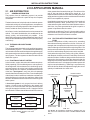
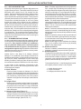
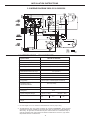
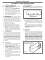
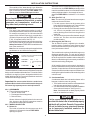
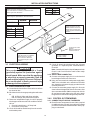
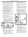
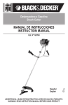
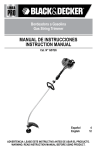
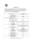
INSTALLATION INSTRUCTIONS
RECORD THIS INFORMATION FOR FUTURE REFERENCE
BEFORE INSTALLING THE UNIT:
Model Number
Serial Number
Date Purchased
Place of Purchase
SELF-CONTAINED
AIR CONDITIONER & HEAT PUMP
FOR
RECREATIONAL VEHICLES
USA
SERVICE OFFICE
Dometic Corporation
2320 Industrial Parkway
Elkhart, IN 46516
574-294-2511
ROTARY COMPRESSOR
SYSTEM MODELS
Air Conditioners
39626.501 & 39626.506
Heat Pumps
39726.501 & 39726.506
CANADA
Dometic Corporation
46 Zatonski, Unit 3
Brantford, ON N3T 5L8
CANADA
519-720-9578
For Service Center
Assistance Call:
800-544-4881
THIS UNIT IS DESIGNED FOR OEM INSTALLATION
ALL INITIAL INSTALLATIONS MUST BE APPROVED BY THE SALES DEPT.
! AVERTISSEMENT
! WARNING
This manual must be read and understood before installation, adjustment, service, or maintenance is
performed. This unit must be installed by a qualified service technician. Modification of this product
can be extremely hazardous and
could result in personal injury or
property damage
Lire et comprendre ce manuel avant de
procéder à l'installation, à des réglages,
de l'entretien ou des réparations.
L'installation de cet appareil doit être
effectuée par un réparateur qualifié.
Toute modification de cet appareil peut
être extrêmement dangereuse et
entraîner des blessures ou dommages
matériels.
US
APPLICATION MANUAL
AND
INSTALLATION INSTRUCTIONS
REVISION:
Form No. 3308463.011 5/06
(Replaces 3308463.003
(French 3308477.011)
©2003 Dometic Corporation
LaGrange, IN 46761
SYSTEM
MODELS
39626.501 39726.501
39626.506 39726.506
Important: Instructions must stay with unit.
Owner read carefully
1
INSTALLATION INSTRUCTIONS
TABLE OF CONTENTS:
1.0
SAFETY INSTRUCTIONS ........................................................................... PAGE 3
2.0
APPLICATION MANUAL ............................................................................. PAGE 4
2.1 AIR DISTRIBUTION ........................................................................... PAGE 4
2.2 HOW ROOM AIR IS RELATED TO OUTLET PERFORMANCE ..... PAGE 7
2.3 SPECIFICATION AND REQUIREMENTS ......................................... PAGE 7
2.4 HIGH-POT REQUIREMENTS ............................................................ PAGE 8
2.5 MOUNTING IN COACH...................................................................... PAGE 9
2.6 WIRING DIAGRAM 39726.501 & 39726.506 ..................................... PAGE 10
2.7 SPECIFICATIONS-HEAT PUMP ....................................................... PAGE 10
2.8 WIRING DIAGRAM 39626.501 & 39626.506 ..................................... PAGE 11
2.9
SPECIFICATIONS - AIR CONDITIONER ......................................... PAGE 11
3.0
INSTALLATION MANUAL ........................................................................... PAGE 12
3.1 GENERAL INSTRUCTIONS .............................................................. PAGE 12
3.2 PROCEDURE .................................................................................... PAGE 12
3.3 ELECTRICAL WIRING ...................................................................... PAGE 14
3.4 CONTROL SYSTEM WIRING ............................................................ PAGE 14
3.5 SYSTEM CONFIGURATION AND CHECK OUT .............................. PAGE 16
2
INSTALLATION INSTRUCTIONS
1.0 SAFETY INSTRUCTIONS
This manual has safety information and instructions to help users eliminate or reduce the risk of
accidents and injuries.
RECOGNIZE SAFETY INFORMATION
!
This is the safety-alert symbol. When you see this
symbol in this manual, be alert to the potential for
personal injury.
Follow recommended precautions and safe operating instructions.
UNDERSTAND, SIGNAL WORDS
A signal word , WARNING OR CAUTION is used
with the safety-alert symbol. They give the level of
risk for potential injury.
! WARNING indicates a potentially hazardous situation which, if not avoided, could result in
death or serious injury.
! CAUTION indicates a potentially hazardous situation which, if not avoided may result in
minor or moderate injury.
CAUTION
used without the safety alert
symbol indicates, a potentially hazardous situation which, if not avoided may result in property
damage.
Read and follow all safety information and instructions.
3
INSTALLATION INSTRUCTIONS
2.0.0 APPLICATION MANUAL
2.1 AIR DISTRIBUTION
2.1.1
GENERAL INFORMATION
The purpose of an air conditioning system is to provide
environmental conditions in a space to keep its occupants
comfortable.
of the greatest heat loss and/or heat gain. The effects of the
gain or loss can then be offset by the supply air. It is
important that the selection of the diffusers and grills for the
supply and return systems receive careful attention to enable
them to accomplish their purpose.
The basic elements of a simple forced circulation air system
consists of a cooling unit, a centrifugal blower, a temperature
sensing device controlling operation of the compressor and
blower, suitable air filters, and a duct system.
Consideration must be given to all aspects of the supply air
distribution patterns: throw, spread, drop, etc. Also, the
outlet and return grille velocities must be held within reasonable limits. Any noise generated at the grille is equal to or
greater in importance than duct noise.
A window air conditioner (Figure 2.2) is essentially a device
with a minimum duct system, since the only items that offer
resistance to air flow are built into the cabinet.
Air is filtered, cooled, and distributed to various areas of the
vehicle. Duct work should deliver this conditioned air as
directly, quietly, and economically as possible. If the
distribution is not properly sized and balanced, flow of air will
not be as calculated and the system will not function properly
or efficiently.
2.1.4
FACTORS AFFECTING RESISTANCE TO AIR
FLOW
Common observations of daily events tell us something
about factors affecting resistance to air flow. We know, for
example, that more pressure is required to force a given rate
of air flow through a small duct than through a large duct. We
also know that streamlining of ducts means less resistance
to air flow, and that sharp angled turns must be avoided.
2.1.2 THE BASIC AIR CONDITIONING
CYCLE
The components which are basic to air conditioning systems
are illustrated by Figure 2.1. Air is treated at the conditioning
unit, transferred to the conditioned space through the supply
duct system and returned to the conditioning unit through the
return system. The duct systems are also referred to as the
distribution system.
As air passes through ducts, cooling coils, grilles, diffusers,
and dampers, the static pressure is reduced by friction and
turbulence losses. Good duct design minimizes the need to
balance the duct system by sizing the ducts such that the
designed pressure drop allows the desired airflow rate to be
delivered to each room. An improperly sized duct system will
require extensive balancing. Balancing is a procedure by
which the air flow allotment is adjusted to supply the correct
quantity of conditioned air to each room.
2.1.3 FUNCTION OF A DUCT SYSTEM
A duct is a tube, or pipe, that carries air between two points.
Strictly speaking, in air conditioning terms, a duct system is
the arrangement of ducts between air conditioning equipment and rooms to be cooled, not including such items as
filters, cooling coils, etc. However, we shall include in our use
of the term “duct system”, every item in the air-passage
network that offers resistance to air flow. From the standpoint
of the blower it makes no difference whether a resistance is
caused by filters or by the use of a small duct; effect will be
the same. Resistance tends to restrict flow of air through the
entire system.
COOL AIR DISCHARGE
INTO ROOM
A forced air system is only as good as its air delivery
system. Comfort levels are affected by the quantity and
velocity of air movement within the space and the proper
mixing of the supply air with the room air. Supply air should
be furnished in a manner that will direct the air to the sources
CONDITIONED
SPACE
RETURN DUCT
SYSTEM
SUPPLY DUCT
SYSTEM
CONDITIONING
UNIT
ROOM
EVAP
AND
FAN
HEATED AIR FROM
CONDENSER DISCHARGED
OUTDOORS
COMPRESSOR,
CONDENSER
AND FAN
OUTDOORS
OUTDOOR AIR TO
CONDENSER
WARM ROOM AIR
TO BE COOLED
Block diagram of comfort air conditioning cycle.
Arrows indicate direction of air flow.
FIG. 2.2
The Window Air Conditioner represents a minimum duct system, since air to and from the cooler is handled without external
ducts.
FIG. 2.1
4
INSTALLATION INSTRUCTIONS
2.1.5 AIR FLOW AND FRICTION
Air flows in a duct system from a region of high pressure to
a region of lower pressure. The blower creates the pressure
differential which causes the air flow through the duct
system. The point of highest pressure in the system is at the
outlet of the blower. The point of lowest pressure in the
system is at the return opening of the blower. The air pressure
constantly decreases as the air flows through the system.
The pressure ultimately diminishes to zero as it passes
through the register and is diffused into the conditioned
space. As air moves through a duct, a pressure drop occurs
due to the friction between the air and the walls of the duct.
Another factor in pressure drop is the turbulence within the
air stream itself. Air moving within a duct does not flow in a
placid stream. Rather it moves in a churning and mixing path,
or “turbulent flow.” The cumulative effect of rubbing friction
and turbulence friction is friction loss. Air turbulence in a duct
system becomes substantial whenever there is a change in
the direction of air flow.
2.1.6 ECONOMICS OF DUCT DESIGN
In order to match to the system air delivery capacity, elbows
for turning the air must be kept as large as allowed by the unit
construction. Duct depth for Dometic air conditioners
may vary with each model series. Confirm the system
to be installed and refer to Figure 3.4, for specific duct
configurations required. High loss elbows must have their
resistance lowered by the use of splitters or turning vanes.
Refer to Figure 2.3 through 2.7.
Item 1. This sharp-angled bend causes a large pressure
loss. A simple way of visualizing such pressure loss is
to imagine that these diagrams represent highways on
which you are driving a car. As you approach a bend you
are forced to slow the car speed to 15 mph. In so doing,
a considerable part of energy of the fast-moving car has
had to be absorbed by the brakes. The analogy holds for
air particles flowing around a sharp bend.
Item 2. This sharp-angled bend on the inside corner
causes great pressure loss. The rounded corner on the
outside does not help as much as might be anticipated.
Item 3. This is a common form of 90° bend that has
relatively low resistance.
Item 4. If minimum resistance is desired, this extreme
example of a smooth, streamlined fitting can be used,
although space requirements will be prohibitive in many
installations.
Item 5. Occasionally, a beam or rafter prevents the use
of a smooth bend and a right angle bend is necessary.
In such cases the use of turning vanes (splitters) will be
effective in reducing resistance.
Item 6. Another way to reduce resistance is to change
item (3) to a modified version of item (4) by inserting
splitters in the sharper bend.
D. Sudden Contraction
When air is suddenly contracted from a large duct to a
small duct, a pressure loss occurs See Figure 2.8.
E. Sudden Expansions
The pressure loss resulting from the sudden expansion
of air from a small duct to a large duct, are much larger
than losses due to sudden contraction. As with sudden
contraction, much can be done by making air expansion
gradual, rather than abrupt. See Figure 2.9.
Another factor in duct losses is air leakage. Although
leakage is not considered in duct design it should be an
installation consideration. Cold air leaking into the surrounding cavity will cause condensation to form under high
humidity conditions. Sealing all joints will assure moisture
free cavities and maximum distribution of air to the outlets.
To summarize Section 2.1.6, the following items contribute to higher pressure losses in a duct system:
In most cases of high resistance encountered in duct
systems, one or more of the following points have been
overlooked by the installer:
A. Small Diameter
Pressure losses increase as diameter of a duct is
reduced. Good design practice is that which enables the
installer to put in the smallest size duct that will do the
job of delivering required airflow rate with pressure
available. No single size of duct will prove to be ideal for
all jobs.
B. Length of Duct
Pressure loss increases as duct length is increased.
This is almost obvious; a duct which is 6 ft. long has twice
the pressure loss of one that is 3 ft. long, provided that
both ducts are the same size and both are carrying the
same airflow rate.
C. Changes in Direction (Figure 2.7)
Pressure losses increase when direction of air flow is
changed. When air is forced to make a 90° turn in a duct
system, pressure loss is much greater than for a straight
run of the same length. (Refer to FIG. 2.7)
1. Smaller diameter ducts
2. Longer duct lengths
3. Changes in direction of air flow
5
INSTALLATION INSTRUCTIONS
EDDIES
FAIR
PREFERRED
(Standard)
ITEM 1
Sharp Angle
ITEM 4
Long Radius Bend
NOT ACCEPTABLE
POOR
Various Elbows Showing Radius Ratios
EDDIES
FIG. 2.3
ITEM 2
Rounded
Outer
Corner
ITEM 5
Splitters, or turning vanes
installed in sharp angle
bend
D
R
RR = R
W
W
ITEM 6
Splitters in rounded
corner bend
ITEM 3
Rounded
Corners
Radius Ratio (RR)
or RR = 1.5
FIG. 2.4
FIG. 2.7
Different ways of making a 90 degree bend. Some
involve greater pressure losses than others.
Rb
LARGE DUCT
ABRUPT
CONTRACTION
D
Ra
CR =
W
Ra
Rb
Curve Ration (CR)
Optimum Reading CR = .05
EDDY
LOSSES
FIG. 2.5
FIG. 2.8
CR =
Pressure losses occur with abrupt reducing fittings.
Ra
Rb
R1 = 2 Ra
R1
CR = .25
Rb
ABRUPT EXPANSION
Ra
CR =
R1
Ra
Rb
R1 = 2 Ra
SMALL
DUCT
(Rb - R1)
2
+ Ra
CR = .15
R2 =
Rb
R2
Ra
LARGE
DUCT
EDDY
LOSSES
FIG. 2.9
Abrupt expansion results in excessive pressure losses.
FIG. 2.6 Using Splitters to reduce resistance.
6
SMALL
DUCT
INSTALLATION INSTRUCTIONS
4. Sudden contractions in air stream
5. Sudden expansions in air stream
2.1.7 REGISTERS, DIFFUSERS, AND GRILLE SELECTION
One of the most important considerations in designing a
conditioning system is the selection of the registers, diffusers and grills. Even though a system delivers the required
amount of conditioned air to the room, discomfort results if
the air is not satisfactorily distributed. Achieving good air
distribution is as much an art as it is a science. Careful
consideration must be given to the design of the air distribution system. A forced air system is only as efficient as its
air delivery components.
most effectively, the high velocity portions of the air stream
have less tendency to enter the occupied zone of the space.
2.2
HOW ROOM AIR MOTION IS RELATED TO
OUTLET PERFORMANCE
The room air near the supply air stream is entrained by the
air stream and, in turn, is replaced by other room air. The
room air always moves toward the supply air. The only
general statement that can be made regarding room air
motion and the number of air changes is that 8 to 10 air
changes per hour are required to prevent formation of stagnant regions.
For most applications, a better approach is to supply air in
such a way that the high velocity air stream from the outlet
does not enter the occupied zone. It is practical to consider
the region within 12 inches of the walls as outside the
occupied zone as well as the region above the heads of the
occupants.
Whenever a jet of conditioned air is admitted into a room it
affects all the air within that room. Movement of the supply air
induces adjacent room air to move along with it. This process
of the supply air dragging along the room air and setting it in
motion is called “entrainment” of the room air. As the room
air mixes with the supply air, the temperature difference
between them is reduced. This effect is even more pronounced with a spreading jet than with a non—spreading jet
because of the greater surface area.
Supply air should be spread in a thin layer over the surfaces,
to surround the occupied zone with conditioned air. Air within
the occupied zone will then move toward the total air stream,
the mixture of primary and room air. The room air carries the
load with it into the air stream and room conditions are
maintained by constant mixing of room and supply air.
2.1.8 ROOM AIR DISTRIBUTION
The final evaluation of air distribution in a space is determined
by the occupants’ comfort level. In general, a person is
thermally comfortable when their body heat loss just equals
their heat production.
During cooling, currents carry warm air up the wall to ceiling
level, and stratification forms from the ceiling down. The
solution is to project cool air into this region near the ceiling.
! WARNING
Improper installation may damage equipment,
could endanger life, cause serious injury and/
or property damage.
2.3
SPECIFICATIONS & REQUIREMENTS
Since it is necessary to install all or part of the duct work in
the ceiling, sidewall or floor.
Performance of any supply outlet is related to initial velocity
and area. As it leaves the outlet, an air jet becomes a mixture
of supply and room air, expanding due to the induction of
room air.
CAUTION
It is the responsibility of the R.V. manufacturer to assure that structural integrity is maintained throughout the coach.
The buoyant forces with non-isothermal jets cause the jet to
rise during heating and drop during cooling. If the jet is
projected parallel to and within a few inches of a surface, the
jet performance will be affected by the surface, which limits
the induction on the surface side of the jet. This creates a low
pressure region between the jet and the surface, which draws
the jet toward the surface. In fact, this effect will prevail if the
angle of discharge between the jet and surface is less than
40°. The surface effect will draw the jet from a ceiling outlet
to the ceiling. Surface effect increases the throw for all types
of outlets and decreases the drop for horizontally projected
air streams.
The manufacturer should review each floor plan to determine
proper duct design and register location.
The Dometic Product Engineering and Application departments are available for recommendations and suggestions.
If the conditioned air is to be discharged from the
ceiling area, the minimum roof cavity thickness for
proper installation measured between the roof and
ceiling structure is 4 inches. This does not include
space required for insulation of the ductwork.
The air stream from the outlet tends to “hug” the surface. As
a matter of fact, this characteristic is almost essential for
good comfort air conditioning. Therefore, rather than trying to
direct the air away from surfaces, the surfaces should be
used intentionally. Note that where the surfaces are used
The air conditioner was designed to allow flexibility for layout
of duct work and the types of registers employed. To ensure
air conditioner maximum performance, certain parameters
must be adhered to. Refer to Figures 3.4 for duct sizing and
grill placement
7
INSTALLATION INSTRUCTIONS
2.3.1 COOLING REQUIREMENTS
When determining the cooling requirements of each vehicle,
the following should be considered:
CAUTION
It is the responsibility of the installer to ensure the duct work will not collapse or bend
during and after installation. Dometic Corporation will not be liable for any structural damage due to improperly insulated, sealed or
collapsed duct work.
A. The size of the vehicle will determine the number of
air conditioning units that are required, or the need
to pre-wire for additional air conditioners depending
on the geographical location of use.
B. Amount of insulation in walls, floor and roof of the
vehicle.
C. Identify possible heat sources and plan accordingly:
1. Skylights - location should not be within 4 feet of
the air conditioner return system.
2. Skylights - should be tinted and double pane.
3. Roof vents should be a tinted type, and quantity kept to minimum.
4. Increased use of slide-outs and/or glass square
footage will require tinting with additional
insulation in wall and ceiling cavities.
5. Calculation of heat producing appliances.
FIG. 2.10
System
P/N
39626
39726
Duct
Size
3x15"
min.
5x16"
max.
Condenser
Inlet Req.
648 in2
Evap.
Static
Inlet Req. Press
135 in2
0.40 - 1.20
2.3.3 AIR DISTRIBUTION DUCT PREPARATION
Depending on the distribution configuration, ensure that the
air entry points have the minimum square inches required for
the series of system installed. See Figure 3.4 for permissible
duct layout. Duct elbows and/or restrictions must be kept to
a minimum. The duct must be pre-built within the structure
and sealed along its entire length. If joints or bends leak
conditioned air within the cavity, condensation will form.
2.3.2
AIR DISTRIBUTION SYSTEM SIZING
Basement systems are designed exclusively with external
ductwork for the cold air discharge. There are not provisions for an electric heater to be installed as part of the
unit. The central furnace will supply heating of the
vehicle, if installed.
When the duct is installed within the structure, care must be
taken to insure that the duct will not collapse or bend during
or after installation of the system to the vehicle.
The condenser section must be installed so as to have direct
access to the outside ambient. Removal of the heated
condenser air is critical for proper operation.
2.3.4 LOCATION OF DISTRIBUTION DUCT
The vehicle itself and the placement of interior components
will dictate the location of the duct. One must be sure that the
registers will not fall near the thermostat or the return filters.
The placement must be such that the air distribution from the
registers will provide the best possible movement within the
living area. Calculations should be made as to the strength
of the cavity, to insure structural integrity if notched for
location of the duct runs.
The installer of this air conditioner must design the air
distribution system for his particular application by following
the guidelines specified within this application manual and
unit installation instructions. Several specific requirements
MUST BE met for the air conditioner to operate correctly:
1. Unit Total Static Pressure See Figure 2.10.
2. Duct Area Requirement. See Figure 2.10.
3. Return air to the system must be filtered to prevent
dirt accumulation on the evaporator cooling surface.
4. Return air opening must be within minimums specified in the system installation instructions. This
figure must include the filter material selected.
5. Since duct work is located within a cavity, it is
necessary that all duct work must be wrapped with
a minimum R7 insulating blanket with a vapor
barrier. This will help prevent heat gain within the
duct and possible condensation.
2.3.5 RETURN REQUIREMENTS
The return air system must be considered when layout of the
duct system is in process. This should be located as near to
the system as possible to insure adequate return back to the
evaporator coil.
2.4
HI-POT REQUIREMENTS
Each system that is built by Dometic is completely checked
electrically and hi-pot tested on our production line. Additional hi-pot testing of the system must not be done.
Disconnect the system from the power circuit prior to any
vehicle high potential test operations.
CAUTION
Dometic Corporation will not be held liable
for roof structural or ceiling damage if the
duct work is not adequately wrapped in an
insulation blanket.
8
INSTALLATION INSTRUCTIONS
2.5.0
MOUNTING IN COACH
The dual basement air conditioner and heat pump are
designed for under the floor installation. It is the vehicle
manufacturer's responsibility to provide an installation space
which will allow for cutouts and mounting of the unit without
cutting vital frame structures. The frame and structural
sections in the installation space will not cause restriction of
air movement required by the dual basement air conditioner
or heat pump. See Figures 2.11, 2.12 and 2.13.
6.5"
7.5"
18"
FIG. 2.11
Condenser
Coil
FIG. 2.12
39626.501
39726.501
Top
Discharge
Condenser
Discharge
5.75"
5.5"
2"
6.5"
36"
22 "
39626.506
39726.506
Side
Discharge
18"
18"
2.75"
9.5"
11.75"
Condenser
Coil Drain
4 Holes
9.5"
Evaporator
Coil
Electrical Box
Wiring Access
FIG. 2.13
4.56"
46"
7.5"
9.31"
Evaporator
Drain Tube
Suggested Placement
Of Supports
Important Notice
All information contained within is for the installation of Dometic Ducted Air Conditioners.
These guidelines give minimum requirements for duct sizing, duct arrangement and register location so that you receive maximum performance from the system.
These instructions DO NOT cover or warrant the
final installation of the duct work that carries
conditioned air within the ceiling cavity.
The installer is responsible for the integrity of the insulated duct within the structure to
insure that moisture laden air does not condense on duct surfaces. If proper practices
are not adhered to, condensation will collect during high ambient conditions. Damage
caused by condensation will not be covered by Dometic Corporation warranties.
9
INSTALLATION INSTRUCTIONS
2.6 WIRING DIAGRAM 39726.501 & 39726.506
EVAP. BLOWER
MOTOR
RED
WHT
WHT
G-Y
G-Y
BLK
BLK
DIP SWITCHES
ON
CIR.#1
12 3 4 5 67 8
P1
115 VAC 60 Hz 1O
USE COPPER CONDUCTORS
ONLY
HERM
K6
COM
P6
RED
FAN
RED
NO NC
BLK
WHT
C
T3
F1
3 AMP FUSE
BRN
BLK
RED
T2
ORN
AMB.
SENSOR
S
BRN
WHT
T4
NC
WHT
RUN
CAP
BLK
OL
C
WHT
RED
T1
NO
FREEZE
CONTROL
P3 P4 P5
WHT
WHT
START
CAP
CIRCUIT
BOARD
K1
COM
P2
FIELD WIRING MUST
COMPLY WITH THE
NATIONAL ELECTRIC CODE
COMPRESSOR
R
COMP
STARTER
VIO
WHT
BLK
BLK
VIO
VIO
REV.
VALVE
ASM
BLK
RED
VIO
BLK
BLK
ORN
BLU
BLU
ELEC.
BOX
BLKHD
YEL
YEL
BRN
BLK
WHT
PASSED
DIELECTRIC
REV.
VALVE
ASM
BLK
BLK
EVAP. COIL
WHT
BRN
MOTOR
CAP
WHT
BRN
ORN
ELEC.
BOX
BLKHD
ORN
GRY
GRY
C
CIR.#2
HERM
RUN
CAP
WHT
BLK
COND. BLOWER
MOTOR
R
COMPRESSOR
BRN
115 VAC 60 Hz 1O
USE COPPER CONDUCTORS
ONLY
GRY
BRN
WHT
BLK
ORN
G-Y
G-Y
WHT
GRY
S
RED
BRN
START
CAP
COMP
STARTER
FIELD WIRING
FACTORY WIRING
= WIRE NUT
2.7 SPECIFICATIONS - HEAT PUMP
System Model
39726.501 & 39726.506*
Nominal BTU Capacity
26,000
Volts/Phase/Hertz (each circuit)
115 AC / 1 / 60
Run Amps Comp
(Circuit 1 =10.0)
(Circuit 2 = 9.8)
LRA Compressor
(Circuit 1 = 59.0)
(Circuit 2 = 59.0)
Total Blwr/Fan Motor Run Amps
8.5 (Circuit 1)
Total Blwr/Fan Motor LRA Amps
18.0 (Circuit 1)
Duct Static - Min. ( In. Water Column)
0.40
Duct Static - Max. ( In. Water Column)
1.20
Generator Size Per/Unit - Min. ***
Wire Size (Up to 24 ft.)**
(Suggested)
7.5K
(Circuit 1) No. 10 AWG Copper Conductors)
(Circuit 2) No. 12 AWG Copper Conductors)
Circuit Protection
Time Delay Fuse or
HACR Circuit Breaker
(Circuit 1) 25Amp
(Circuit 2) 15Amp
Control Voltage
12V DC
Refrigerant
R-22
System Refrigerant Charge
(Circuit 1 = 46.5)
Size (In Inches)
Width
46
Installed
Weight
*
(Circuit 2 = 38.5)
Height
18
Depth
22
205 Pounds
Models ending with .506 suffix and manufactured with "SIDE AIR DISCHARGE".
** For wire lengths over 24 ft. consult the National Electric Code for proper sizing.
*** The Manufacturer gives only general guidelines for generator requirements. These generator
requirements come from experiences consumers have with our equipment in field applications.
When sizing the generator, the total electrical power must be taken into consideration. Keep in
mind that generators lose power because of altitude increases above sea level , high outdoor
temperatures and lack of maintenance.
10
OL
C
3108345.095
INSTALLATION INSTRUCTIONS
2. 8 WIRING DIAGRAM 39626.501 & 39626.506
EVAP. BLOWER
RED
WHT
WHT
G-Y
G-Y
T1
BOARD
K1
6 7 8
ONLY
P2
P3
P4
FREEZE
CONTROL
P5
NC
COMPLY WITH THE
NATIONAL ELECTRIC CODE
T3
C
BLK
WHT
RUN
K6
COM
P6
RED
WHT
FAN
F1
3 AMP FUSE
BRN
BLK
HERM
RED
ORN
AMB.
SENSOR
FIELD WIRING MUST
S
RED
T2
NO
BRN
WHT
COM
1 2 3 4 5
P1
NO
NC
WHT
CAP
BLK
OL
C
WHT
RED
CIRCUIT
ON
CIR.#1
115 VAC 60 Hz 1 PHASE
WHT
WHT
START
CAP
DIP SWITCHES
USE COPPER CONDUCTORS
COMPRESSOR
R
BLK
BLK
MOTOR
COMP
STARTER
BLK
RED
BLK
BLK
ORN
BLU
WHT
BLU
BRN
ELEC.
BOX
BLKHD
YEL
YEL
BLK
PASSED
DIELECTRIC
EVAP. COIL
WHT
BRN
MOTOR
CAP
BRN
ORN
ORN
GRY
GRY
WHT
RUN
C
CIR.#2
BLK
COND. BLOWER
CAP
R
MOTOR
HERM
BRN
115 VAC 60 Hz 1 PHASE
USE COPPER CONDUCTORS
BRN
WHT
BLK
ORN
G-Y
G-Y
WHT
GRY
OL
C
GRY
ONLY
COMPRESSOR
S
RED
BRN
START
CAP
COMP
STARTER
FIELD WIRING
FACTORY WIRING
= WIRE NUT
2.9 SPECIFICATIONS - AIR CONDITIONER
System Model
39626.501 & 39626.506*
Nominal BTU Capacity
26,000
Volts/Phase/Hertz (each circuit)
115 AC / 1 / 60
Run Amps Comp
(Circuit 1 = 10.1)
LRA Compressor
(Circuit 1 = 59.0)
(Circuit 2 = 59.0)
Total Blwr/Fan Motor Run Amps
8.5 (Circuit 1)
Total Blwr/Fan Motor LRA Amps
18.0 (Circuit 1)
Duct Static - Min. ( In. Water Column)
0.40
Duct Static - Max. ( In. Water Column)
1.20
Generator Size Per/Unit - Min. ***
7.5K
Wire Size (Up to 24 ft.) **
(Suggested)
(Circuit 1) No. 10 AWG Copper Conductors)
(Circuit 2) No. 12 AWG Copper Conductors)
Circuit Protection
Time Delay Fuse or
HACR Circuit Breaker
(Circuit 1) 25Amp
(Circuit 2) 15Amp
Control Voltage
12V DC
Refrigerant
R-22
System Refrigerant Charge
(Circuit 1 = 46.5)
Size (In Inches)
Width
46
(Circuit 2 = 38.5)
Height
18
Installed
Weight
*
(Circuit 2 = 9.8)
Depth
22
205 Pounds
Models ending with .506 suffix and manufactured with "SIDE AIR DISCHARGE".
** For wire lengths over 24 ft. consult the National Electric Code for proper sizing.
*** The Manufacturer gives only general guidelines for generator requirements. These generator
requirements come from experiences consumers have with our equipment in field applications.
When sizing the generator, the total electrical power must be taken into consideration. Keep in
mind that generators lose power because of altitude increases above sea level , high outdoor
temperatures and lack of maintenance.
11
3108345.061
INSTALLATION INSTRUCTIONS
3.0.0 INSTALLATION INSTRUCTIONS
3.1
GENERAL INFORMATION
3.2.0 PROCEDURE
3.1.1
A.
THIS UNIT IS DESIGNED FOR:
Installation in a recreational vehicle at the time the
vehicle is manufactured.
Heating operation in a MILD GEOGRAPHICAL
AREA where the heat loss is minimal.
Turning "OFF" the heat pump and switching to
furnace (aux. heat) when the outside temperature is below 30 degrees Fahrenheit.
Returning to heat pump when the temperature
returns to 38 degrees Fahrenheit.
3.2.1 LOCATION
This system is intended for installation in a recreational vehicle
where the interior is essentially one undivided space. (See FIG.
3.1)
B.
C.
D.
FIG. 3.1
3.1.2 HEAT GAIN/LOSS
The ability of the heat pump/air conditioner to maintain
the desired inside temperature depends on the heat
gain/loss of the RV. Some preventative measures
taken by the occupants of the RV can reduce the heat
gain and improve the performance of the unit. During
extremely high outdoor temperatures, the heat gain of
the vehicle may be reduced by:
A. Parking the RV in a shaded area.
B. Using window shade (blinds and/or curtains)
C. Keeping windows and doors shut or minimizing usage.
C. Avoiding the use of heat producing appliances.
Starting the unit early in the morning and giving it a
"head start" on the expected high outdoor ambient
will greatly improve its ability to maintain the desired indoor temperature.
3.1.3
CONDENSATION:
Dometic Corporation will not be responsible for damage caused by condensed moisture on ceilings, walls
or other surfaces. Air contains moisture and this
moisture tends to condense on cold surfaces. When
air enters the RV, condensed moisture may appear on
the ceiling, windows, metal parts, etc.. The unit removes this moisture from the air during normal operation. Keeping doors and windows closed when the unit
is in operation will minimize condensed moisture on
cold surfaces.
3.1.4
A.
B.
C.
D.
E.
POSSIBLE LOCATIONS
A. The unit is to be installed below the floor with DIRECT
access to outside air for the outside coil.
B. The thermostat cable maximum length is twenty-five (25)
feet. Total length of cable used (including thermostat)
for the control system is seventy-five (75) feet maximum.
C. The unit should be protected as much as possible from
the elements. Do not locate unit where road spray,
rocks, etc. will hit the unit.
Note: The fins of the outside coil should face the exterior
of the vehicle.
3.2.2 OUTSIDE COIL
A. Supply Air
The inlet of the outside coil should be positioned so that
it draws air from outside the vehicle. Special care must
be taken to prevent the discharge air from recirculating to the inlet of the outside coil. If unit is
installed in a compartment, the discharge air must
be open to the outside. The recirculation of condenser air within the compartment will cause high
internal operation pressures and tripping of breakers will occur. Compartment cannot be sealed.
Shields should be added to ensure fresh air supply. See
FIG. 3.2
PRECAUTIONS:
Read Installation Instructions carefully before
attempting to start your unit installation.
Dometic Corporation will not be liable for any
damages or injury incurred due to failure in the
following of these instructions.
Installation must comply with the National Electric Code ANSI/NFPA-70 and CSA Standard
C22.1 (latest edition) and any State or Local
Codes or regulations.
DO NOT add any devices or accessories to the
unit except those specifically authorized by
Dometic Corporation.
This equipment must be serviced by qualified
personnel and some states require these people
to be licensed.
Shields Installed To Prevent
Recirculation Of Outside Air.
FIG. 3.2
12
INSTALLATION INSTRUCTIONS
Where the return air must be provided through louvers
or mesh screen, the FREE AREA percentage of the
material used shall be taken into consideration when
making this determination. An example of how to
determine FREE AREA is included in "3.2.2. Outside
Coil".
B. Grills (See FIG. 3.4)
Note: The return air grill must have the same square
surface as the return air duct.
1. For each system, there must be a return grill to
bring vehicle air back into the unit. There must also
be at least four discharge grills per unit.
2. Return grills must be mounted in front of the inside
coil. If this is not possible, make sure there is
nothing blocking the air flow from the grill to the
inside coil.
3. The unit must have a return filter between the grill
and the unit. This filter must be accessible for
periodic cleaning.
C. Discharge Air (See FIG. 3.4)
The air diffusion system, supplied by the installer,
must be sized to maintain a static pressure at the
blower outlet between 0.40 (minimum) and 1.20 (maximum) inches water column.
The outside coil is a "draw-through" type. When the
face of the coil is positioned behind a louvered or other
type of restrictive opening, the FREE AREA of the
opening must be at least 648 square inches.
CAUTION
Do not install the unit where the fan will draw
air from the exhaust of the vehicle, a motor
generator set, transmission, road heat or
any other heat producing source.
B. Free Area
Free area is the opening that remains in a grill or
louvered panel after the restrictions are taken away.
For example, an opening of 10 x 20 inches has 200
square inches. When this opening is covered with a
grill that is 56 percent open the FREE AREA is (200
x .56), 112 square inches. See FIG. 3.3.
Expanded and perforated metal grills in general vary
from 30 percent to 60 percent open. Be certain that
648 square inches of FREE AREA is available to the
face of the outside coil.
Note: Service access must always be supplied either
as clearance or as a defined access panel.
FIG. 3.3
8
1/2
EXAMPLE OF HOW TO DETERMINE FREE
AREA OR % OPEN AREA:
1/2
TOTALAREA =
8X8
FREE AREA
=
=
2 X 2 X 9 openings
36
% OPEN AREA
=
36
64
2
8
=
The installer has the options of side discharge or top
discharge and side return. The unit can be ordered
originally with the inside blower mounted to discharge
the air as required. If the installer needs to change the
direction of the discharge it is necessary to rotate the
inside blower housing 90 degrees.
64
2
1/2
2
1/2
=
All air handling ducts must be properly insulated to
prevent condensation forming on their surface during
operation. A vapor barrier must also be supplied on the
outer surface of the insulation to prevent moisture from
traveling through the insulation and condensing on the
cold duct work.
56%
3.2.3 MOUNTING
The Model 39626 Air conditioner and 39726 Heat Pump units
design are for installation below the floor. This unit should be
mounted in an angle-iron frame, designed and built for the
Model 39626 and 39726. Frame rails should not restrict the
condenser air discharge opening.
D. Condensate Drain
A condensate drain tube is located on bottom of the
base pan, under the return air opening.
1. The installer needs to install the condensate drain
into the base pan and ensure a snug fit.
2. A 3" diameter hole must be provided for installation
of the tube and clearance. See Figure 2.11.
Note: Condensate will not drain properly if drain
tube is not installed or missing.
Important: Do not mount the Units in a sealed compartment. Recirculation of hot condenser discharge air
will cause high system pressure and trip breakers.
3.2.4 CLEARANCES
A. The unit clearances depend on:
1. Inlet air access used;
2. Discharge air duct arrangement;
3. Return air duct;
CAUTION
Allow a minimum of eight (8) inches for the return air
duct. Access to the electrical connections must be
provided when making the installation.
3.2.5 INSIDE COIL SECTION
A. Return Air
The inside coil must have free access to room air. A
minimum of 135 square inches of FREE AREA
opening is required.
It is the responsibility of the installer to ensure that the drain tube is installed properly
and that it will not leak. Dometic Corporation
will not be liable for any structural damage
due to improperly installed, sealed or restricted drain tube.
13
INSTALLATION INSTRUCTIONS
RETURN SYSTEM
Return to be 6 ft. minimun from floor.
Use wall structure for delivery to basement area.
Return grille must be filtered.
INSULATED DUCT
Minimum
Maximum
45 IN. 2
80 IN. 2
(3 " depth Min.)
FIG. 3.4
Minimun return required per duct sizing for unit to perform
within Engineer specifications. See Chart below.
MINIMUM
SIDE RETURN
135IN.2
MAXIMUM
291 IN.2
ADDITIONAL REQUIREMENTS:
Damper required in furnace.
Vibration isolators should be
used at each mounting point.
12 VDC required for thermostat
operation.
REGISTER REQUIREMENTS
REQ. SIZE
MIN. QTY.
4X6
8
4X8
6
4 X 10
5
4 X 12
4
Condenser air inlet.
Condenser air outlet
(bottom)
Must be isolated from
condenser inlet air.
Supply Duct must be insulated.
Supply Duct from air conditioner
must be equal to or greater
in IN.2 as the floor ductwork.
Use 45 degree angle on inlets
& outlets
3.3
Electric box access required.
Circuit #1 - 25 Amp
Circuit #2 - 15Amp
E. Circuit #2 should be wired through the on-board
generator or a separate power cord dedicated to
Circuit #2.
Note: A standard 30 amp hookup will not power both
Circuit 1 and Circuit 2 and the coach's other major
appliances.
3.3.2 SUPPLY WIRE CONNECTION
A. Connect main power supply Cir. #1 to unit electrical
box with approved Romex connectors.
B. Using wire nuts attach the main power supply black
"Hot" to the units black wire, and white to the white
wire. Attach the main power supply ground wire to the
Green w/yellow wire.
C. Connect the secondary power supply Cir. #2 to unit
electrical box with approved Romex connectors. Use
wire nuts to attach black "Hot" to orange wire of circuit
#2. and power supply white to the gray wire. Attach
the ground wire of circuit #2 to the green w/yellow wire.
ELECTRICAL WIRING
! WARNING
This product is equipped with a 3-wire
(grounded) system for protection against
shock hazard. Make sure that the appliance
is wired into a properly grounded 1volt AC
circuit and the polarity is correct. Failure to
do so could result in death, personal injury
or damage to the equipment.
3.3.1 SUPPLY WIRE INSTALLATION
A. Locate the unit electrical box. Remove the cover from
the electrical box.
B. Each electrical circuit are grouped together with a wire
tie.
CIR. #1: Black, White and Green w/yellow
CIR. #2: Orange, Gray and Green w/yellow
C. Route two independent supply circuits of properly
sized copper conductors to the air conditioner electrical box.
1. Circuit #1 should carry a 25 Amp load.
2. Circuit #2 a 15 Amp load.
D. Circuit #1 should be wired directly from the coach's
main breaker panel.
3.4.0 CONTROL SYSTEM WIRING
3.4.1 CONNECTION OF LOW VOLTAGE WIRES
A. Route Remote Temperature Sensor Cable, (required
for additional units or if used), through the low voltage
port on the electrical box and attach it the "white (P4)"
plug on main board.
14
INSTALLATION INSTRUCTIONS
4. Avoid locations close to doors that lead outside,
windows or adjoining outside walls;
5. Avoid locations close to supply registers and the
air from them;
6. Never locate CCC in a room that is warmer or
cooler than the rest of the coach - such as the
kitchen;
7. The major living area is normally a good location.
Note: If the system is to be used with a Remote
Temperature Sensor, the Comfort Control Center
may be mounted anywhere that is convenient in
the coach.
8. Try to avoid hard to reach or hard to see areas.
9. Refer to the instructions provided with the Remote
Temperature Sensor for details of installation.
B. Comfort Control Center™ Installation
1. Carefully remove the base plate from the Comfort Control Center™. This may be accomplished
by inserting a small screwdriver under the tab on
the bottom edge of the front cover and gently prying. See FIG. 3.6.
B. Route a dedicated DC supply line (18-22 AWG copper
conductors) from the Converter or Battery to the
unit's electrical box. Connect with wire nuts positive
(+) DC to the red wire; Negative (-) DC to the black
wire.
C. Route thermostat wires from the furnace (if applicable)
to the electrical box and attached them to the blue
wires extending from the main board. The polarity of
these connections does not matter.
D. Route the Energy Management System 2 wires (if
applicable) to the electrical box and connect them to
the yellow wires extending from the main board. The
polarity of these wires does not matter.
Note: If yellow wires are not used and a circuit is made
between them, the unit will fail to operate.
3.4.2 CONTROL CABLE INSTALLATION
A. A 4-conductor flat control cable, must be routed between the Comfort Control Center (CCC) and the electrical box. The maximum length of all control
cables is seventy-five (75) feet.
B. Select the shortest direct route between Comfort
Control Center TM and the electrical box for the system.
C. A 3/8" diameter hole will be needed to route the control cable through the wall.
D. Leave 6" of cable extending through the wall.
E. The cable that must be used is a 4-conductor flat
control cable.
F. The cable must be terminated with two RJ-11 telephone connectors. Refer to the crimp tool manufacturer for crimping instructions. Be sure the cable
is installed correctly into the connector before it is
crimped. Polarity is important and a standard
pre-made telephone cable will not work.
Note: RJ-11 connectors must be wired identically
on both ends. See FIG. 3.5.
FIG. 3.6
DE
MO
N
FA
UP
P
TEM
WN
DO
NE
ZO
F
OF
FIG. 3.5
ON
Insert Screwdriver
under Tab
2. Insert the control cable through the hole in the
base plate and mount the plate to the wall with
the two screws provided. Check the alignment to
ensure level installation.
3. Install the control cable RJ-11 connector into the
back of the Comfort Control Center™ and gently press onto the base plate.
4. If a Remote Temperature Sensor is to be used,
the connector end must be routed to the electri
cal control box and connected to the color matching plug on the relay board.
5. If a furnace is to be controlled by the system, the
two furnace thermostat leads must be routed to
the electrical control of the air conditioner that will
control it. Make sure at least 15" of the furnace
thermostat wires extend into the electrical control box.
G. Plug the communications cable(s) into one of the
telephone jack(s) on the circuit board in the electrical box. (It does not matter which one.)
3.4.3 COMFORT CONTROL CENTER MOUNTING
A. Location
The proper location of the Comfort Control Center
(CCC) is very important to ensure that it will provide a
comfortable RV temperature. Observe the following
general rules when selecting a location.
1. Locate the CCC about 54" above the floor;
2. Install CCC on a partition, not on an outside wall;
3. Direct heat from lamps, sun or other heat producing items will cause erratic operation and temperatures;
15
INSTALLATION INSTRUCTIONS
6. If an Energy Management System - EMS (load
shed) is to be used with the control, two wires
must be routed to the electrical control box. The
signal required for this function is a normally open
relay contact. When the EMS calls for the compressor to shut off, the relay contacts should
close. Make sure that at least 15" of the EMS
wires extend into the electrical box.
7. In the event that other units are to be installed
(additional zones), an additional 4-conductor communications cable must be routed to the other
locations Make sure that at least 15" of the wire
extends into each of the electrical control boxes.
3.5
E. Turn "ON" the furnace dip switch when a furnace is
connected to the blue wires off the control board.
F. Differential dip switch is the difference between the
"ON/OFF" cycle of the thermostat. The normal differential is preset in the circuit board with the dip
switch set to the "OFF" positions. In some situations,
it may be necessary to decrease the Differential.
The location of the Comfort Control CenterTM may
create a condition where the normal differential will
not maintain the temperature at your comfort level. If
this occurs, the Differential can be shortened by placing the Differential dip switch to the "ON" position.
G. The "GEN START" dip switch - leave in the "OFF"
position.
3.5.2 SYSTEM RESET
On new installation the COMFORT CONTROL CENTER TM,
and/or any changes made to the dip switches requires the
electronic control kit to be reset.
A. Turn "ON/OFF" switch to the "OFF" position.
B. Simultaneously depress and hold the "MODE" and
"ZONE" push-buttons while turning the "ON/ OFF"
switch to "ON". The LCD Display should show "FF"
until the "MODE" and "ZONE" push-buttons are released.
3.5.3 System Checkout
A. Verify that all features of the installed system work.
Check fan speeds, cooling mode, furnace (if connected) and heat pump. If the features do not work,
check all wiring and confirm that the correct options
have been selected on the Electronic Control Box.
3.5.4 Service And Disposal Of Unit
A. The Clean Air Act of 1990 set guidelines in regards
to recapturing or disposition of refrigerants. Service
agents working with reclamation of refrigerants must
be certified by the Environmental Protection Agency
(EPA). Check with the EPA authorities for proper handling or evacuation of refrigerants.
SYSTEM CONFIGURATION & CHECK
OUT
Now that the system is installed, it is necessary to configure the electronics, and then check all operations. If the
installation is a single zone, (Without a Furnace) no adjustment to the dip switches are necessary: however, the stage
dip switch is preset to the "ON" position.
3.5.1 ELECTRONIC CONTROL CONFIGURATION
A. If there is more than one zone, the dip switch for
each successive zone must be set to "ON". To gain
access to the dip switches the cover on the unit's
electrical box must be removed.
B. Turn "ON" the "ZONE" dip switch on the electronic
control board to set its zone. See figure 3.7.
ZONE 4
FURNACE
DIFFERENTIAL
STAGE
GEN START
HEAT STRIP
ZONE 2
ZONE 3
FIG. 3.7
ON
1 2 3 4 5 6 7 8
NOTE: The Control Board should have the Stage Dip
Switch preset to "ON". All other dip switches are
shipped from the factory in the "OFF" position.
C. Turning "ON" of zone 2 dip switch identifies this as
zone 2: likewise zone 3 and 4.
D. Stage dip switch is to be in the "ON" position. This
will control the operation of the second compressor,
provided AC power is available to Circuit #2. The temperature differential between the first and second stage
is preset and cannot be changed.
16