1
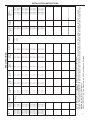
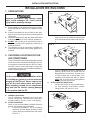
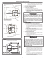
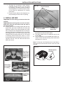
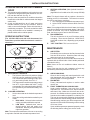
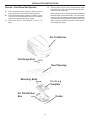
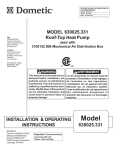
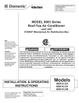
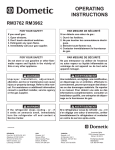
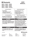
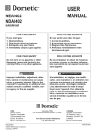
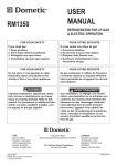
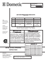
INSTALLATION INSTRUCTIONS RECORD THIS UNIT INFORMATION FOR FUTURE REFERENCE: Model Number Serial Number Date Purchased AIR DISTRIBUTION BOX KITS Patents Pending USA SERVICE OFFICE Dometic Corporation 2320 Industrial Parkway Elkhart, IN 46516 574-294-2511 CANADA Dometic Distribution 46 Zatonski, Unit 3 Brantford, Ontario CANADA N3T 5L8 519-720-9578 For Service Center Assistance Call: 800-544-4881 Product Type For Use With Electric Heat 3310700 Mechanical Controls 520 Series/ 600 Series Opt Kit/Not Avail 3310741 Mechanical Controls 520300/600 Series Not Available 3310742 Electronics Pre-installed 6204, 6205, Pre- Installed In Unit 6206, 6207, 6305 In Unit (Except 6305) Note: Installation requires a #2 phillips screwdriver with 9/32" maximum diameter x 1-1/4" minimum This manual must be read and understood before installation, adjustment, service, or maintenance is performed. This unit must be installed by a qualified service technician. Modification of this product can be extremely hazardous and could result in personal injury or property damage. 520300.501 520310.501 520315.501 520315.506 520315.701 520315.706 520316.301 520316.306 520316.501 520316.506 520316.701 INSTALLATION & OPERATING INSTRUCTIONS REVISION: Form No. 3310861.038 11/07 (Replaces 3310861.020) (French 3310931.039) ©2007 Dometic Corporation LaGrange, IN 46761 Lire et comprendre ce manuel avant de procéder à l'installation, à des réglages, de l'entretien ou des réparations. L'installation de cet appareil doit être effectuée par un réparateur qualifié. Toute modification de cet appareil peut être extrêmement dangereuse et entraîner des blessures ou dommages matériels. Important: These instructions must stay with unit. Owner read carefully. MODELS 520316.706 600312.331 600315.331 600315.336 620412.331 620415.331 620415.336 620425.331 620425.336 620426.331 620426.336 620515.331 620515.336 620525.331 620525.336 620526.331 620526.336 620615.331 620615.336 620625.331 620625.336 620626.331 620626.336 620712.331 620715.331 620725.331 620726.331 630515.331 630515.336 630516.331 630516.336 630715.331 630716.331 INSTALLATION INSTRUCTIONS Safety Instructions GENERAL INFORMATION A. This air conditioner is designed for: 1. Installation on a recreational vehicle during or after the time the vehicle is manufactured. 2. Mounting on the roof of a recreational vehicle. 3. Roof construction with rafters/joists on minimum of 16 inch centers. 4. Minimum of 1.00 inch and maximum of 5.5 inches distance between roof to ceiling of recreational vehicle. B. The ability of the air conditioner to maintain the desired inside temperature depends on the heat gain of the RV. Some preventative measures taken by the occupants of the RV can reduce the heat gain and improve the performance of the air conditioner. During extremely high outdoor temperatures, the heat gain of the vehicle may be reduced by: 1. Parking the RV in a shaded area 2. Using window shades (blinds and/or curtains) 3. Keeping windows and doors shut or minimizing usage 4. Avoiding the use of heat producing appliances Operation on High Fan/Cooling mode will give optimum or maximum efficiency in high humidity or high outside temperature. This manual has safety information and instructions to help users eliminate or reduce the risk of accidents and injuries. Recognize Safety Information This is the safety-alert symbol. When you see this symbol in this manual, be alert to the potential for personal injury. Follow recommended precautions and safe operating instructions. Understand Signal Words A signal word , WARNING OR CAUTION is used with the safety-alert symbol. They give the level of risk for potential injury. Starting the air conditioner early in the morning and giving it a "head start" on the expected high outdoor ambient will greatly improve its ability to maintain the desired indoor temperature. For a more permanent solution to a high heat gain, accessories like A&E outdoor patio and window awnings will reduce heat gain by removing the direct exposure to the sun. They also add a nice area to enjoy company during the cool of the evening. indicates a potentially hazardous situation which, if not avoided, could result in death or serious injury. C. Condensation Note: The manufacturer of this air conditioner will not be responsible for damage caused by condensed moisture on ceilings or other surfaces. Air contains moisture and this moisture tends to condense on cold surfaces. When air enters the RV, condensed moisture may appear on the ceiling, windows, metal parts, etc. The air conditioner removes this moisture from the air during normal operation. Keeping doors and windows closed when this air conditioner is in operation will minimize condensed moisture on cold surfaces. indicates a potentially hazardous situation which, if not avoided may result in minor or moderate injury. used without the safety alert symbol indicates, a potentially hazardous situation which, if not avoided may result in property damage. Read and follow all safety information and instructions. *** * ** 15,000 15,000 13.500 13,500 12.0 12.0 12.4 12.4 64.0 64.0 60.0 60.0 53.0 60.0 60.0 60.0 60.0 3.3 3.3 3.5 3.5 3.1 3.1 3.1 3.1 3.1 8.5 8.5 10.0 10.0 8.8 8.8 8.8 8.8 8.8 7.6 7.6 8.8 8.8 8.8 380 380 335 335 335 335 335 335 335 375 375 375 375 375 21.5 21.5 16.5 16.5 16.5 15.5 15.5 15.5 15.5 30.0 30.0 17.0 15.2 15.2 20 Amp 20 Amp 20 Amp 20 Amp 20 Amp 20 Amp 20 Amp 20 Amp 20 Amp 20 Amp 20 Amp 20 Amp 20 Amp 20 Amp 20 Amp 20 Amp 20 Amp 20 Amp 20 Amp 104 104 95 95 95 95 95 95 95 105 105 95 95 95 91 105 105 105 105 3.5 KW - 5.0KW 3.5 KW - 5.0 KW 3.5 KW - 5.0 KW 3.5 KW - 5.0 KW 2.5 KW - 4.0 KW 3.5 KW _5.0 KW 3.5 KW - 5.0 KW 3.5 KW - 5.0 KW 3.5 KW - 5.0 KW 3.5 KW / 5.0 KW 3.5 KW / 5.0 KW 2.5 KW/ 4.0 KW 3.5 KW / 5.0 KW 3.5 KW / 5.0 KW For wire lengths over 24 ft. consult the National Electric Code for proper sizing. Dometic Corporation gives GENERAL guidelines for generator requirements. These guidelines come from experiences people have had in actual applications. When sizing the generator, the total power usage of your recreational vehicle must be considered. Keep in mind generators lose power at high altitudes and from lack of maintenance. CIRCUIT PROTECTION: Time Delay Fuse or HACR Circuit Breakers Required. 620426.331 620426.336 620515.331 620515.336 9.5 12.4 12.4 12.4 12.4 2.65 2.65 2.8 3.1 3.1 16.5 30.0 30.0 30.0 30.0 11,000 13,500 13,500 13,500 13,500 62.0 62.0 53.0 60.0 60.0 375 375 375 375 375 620412.331 620415.331 620415.336 620425.331 620425.336 12.6 12.6 9.5 12.4 12.4 8.5 7.6 7.6 7.6 7.6 15,000 15,000 11,000 13,500 13,500 3.0 2.8 2.8 2.8 2.8 520316.701 520316.706 600312.331 600315.331 600315.336 58.0 60.0 60.0 79 79 3.5 KW / 5.0 KW 3.5 KW / 5.0 KW 3.5 KW / 5.0 KW 3.5 KW - 5.0 KW 3.5 KW - 5.0 KW 12.0 13.2 13.2 13.2 13.2 13,500 15,000 15,000 15,000 15,000 520315.706 520316.301 520316.306 520316.501 520316.506 MINIMUM GENERATOR SIZE** 1UNIT/2UNITS 2.4 KW / 4.0 KW 2.4 KW / 4.0 KW 3.5 KW / 5.0 KW 3.5 KW / 5.0 KW 3.5 KW / 5.0 KW SPECIFICATIONS MODEL NOMINAL ELECTRICAL COMPRESSOR COMPRESSOR FAN MOTOR FAN MOTOR SCFM-HIGH REFRIGERANT MINIMUM AC CIRCUIT INSTALLED NO. CAPACITY RATING RATED LOAD LOCKED RATED LOAD LOCKED SPEED R-22 (OZ) WIRE SIZE* PROTECTION WEIGHT (BTU/HR) AMPS ROTOR AMPS ROTOR MAX/MIN *** USER (POUNDS) COOLING AMPS AMPS SUPPLIED 120 VAC, 520300.501 N/A 7.8 49.0 3.0 8.5 375 20.0 15 Amp 89 12 AWG 60 HZ., 1PH. 520310.501 9,000 7.8 49.0 3.0 8.5 375 20.0 20 Amp 89 Copper 520315.501 13,500 10.3 62.0 3.0 8.5 375 16.5 20 Amp 91 up to 24’ 520315.506 13,500 10.3 62.0 3.0 8.5 375 16.5 20 Amp 91 520315.701 13,500 12.0 58.0 3.0 8.5 375 16.5 20 Amp 91 INSTALLATION INSTRUCTIONS 60.0 64.0 64.0 60.0 64.0 630515.33613,50012.4 630516.33115,00012.0 630516.33615,00012.0 630715.33113,50012.4 630716.33115,00012.0 *** REFRIGERANT MINIMUM 3.510.0 3.3 8.2 3.3 8.2 3.510.0 3.3 8.2 3.510.0 3.510.0 3.510.0 3.3 8.2 3.510.0 3.510.0 3.510.0 3.510.0 3.3 8.2 3.3 8.2 3.510.0 3.510.0 3.3 8.2 3.3 8.2 3.510.0 335 335 335 335 335 23.5 20.0 20.0 23.5 20.0 33517.0 33516.5 33516.5 335 20.0 335 23.5 33515.2 33515.2 33515.2 335 20.0 335 20.0 33516.5 12 AWG 33516.5 Copper 380 20.0 up to 24’ 380 20.0 33515.2 LOCKED SPEED R-22 (OZ) WIRE SIZE* ROTOR MAX/MIN AMPS SCFM-HIGH SPECIFICATIONS FAN MOTOR INSTALLED MINIMUM 20 Amp 20 Amp 20 Amp 20 Amp 20 Amp 20 Amp 20 Amp 20 Amp 20 Amp 20 Amp 20 Amp 20 Amp 20 Amp 20 Amp 20 Amp 20Amp 20 Amp 20 Amp 20 Amp 20 Amp 98 95 95 95 95 98 98 98 98 98 98 98 98 98 98 95 95 95 95 98 3.5 KW - 5.0 KW 3.5 KW - 5.0 KW 3.5 KW - 5.0 KW 3.5 KW - 5.0 KW 3.5 KW - 5.0 KW 2.5 KW - 4.0 KW 3.5 KW - 5.0 KW 3.5 KW - 5.0 KW 3.5 KW - 5.0 KW 3.5 KW -5.0 KW 3.5 KW - 5.0 KW 3.5 KW - 5.0 KW 3.5 KW - 5.0 KW 3.5 Kw - 5.0 KW 3.5 Kw - 5.0 KW 3.5 KW - 5.0 KW 3.5 KW - 5.0 KW 3.5 KW - 5.0 KW 3.5 KW - 5.0 KW 3.5 Kw - 5.0 KW PROTECTION WEIGHT GENERATOR *** USER (POUNDS) SIZE** SUPPLIED1 UNIT/ 2 UNITS AC CIRCUIT For wire lengths over 24 ft. consult the National Electric Code for proper sizing. Dometic Corporation gives GENERAL guidelines for generator requirements. These guidelines come from experiences people have had in actual applications. When sizing the generator, the total power usage of your recreational vehicle must be considered. Keep in mind generators lose power at high altitudes and from lack of maintenance. CIRCUIT PROTECTION: Time Delay Fuse or HACR Circuit Breakers Required. 53.0 60.0 60.0 64.0 60.0 620712.33111,000 9.5 620715.33113,50012.4 620725.33113,50012.4 620726.33115,00012.0 630515.33113,50012.4 60.0 60.0 64.0 64.0 60.0 60.0 60.0 60.0 64.0 64.0 * ** FAN MOTOR LOCKED RATED LOAD ROTOR AMPS AMPS COMPRESSOR 620615.33613,50012.4 620625.33113,50012.4 620625.33613,50012.4 620626.33115,00012.0 620626.33615,00012.0 620526.33115,00012.0 620526.33615,00012.0 620615.33113,50012.4 120 VAC, 620525.33113,50012.4 60 HZ., 1PH. 620525.33613,50012.4 CAPACITY RATING RATED LOAD (BTU/HR) AMPS COOLING COMPRESSOR NO. ELECTRICAL NOMINAL MODEL INSTALLATION INSTRUCTIONS INSTALLATION INSTRUCTIONS 1. PRECAUTIONS INSTALLATION INSTRUCTIONS FIG. 1 1/2 L L Improper installation may damage equipment, could endanger life, cause serious injury and/or property damage. A. Read installation and operating instructions carefully before attempting to start your air conditioner installation. B. Dometic Corporation will not be liable for any damages or injury incurred due to failure in following these instructions. C. Installation must comply with the National Electrical Code and any State or Local Codes or regulations. D. DO NOT add any devices or accessories to this air conditioner except those specifically authorized in writing by Dometic. E. This equipment must be serviced by qualified personnel and some states require these people to be licensed. 2. For two unit installations: Install one air conditioner 1/3 and one air conditioner 2/3 from front of RV and centered from side to side. See FIG. 2. FIG. 2 L 2/3 L 1/3 L 2. CHOOSING LOCATION FOR THE AIR CONDITIONER This air conditioner is specifically designed for installation on the roof of a recreational vehicle (RV).The roof must support 130 pounds when the RV is in motion. Normally a 200 lb. static load design will meet this requirement. Insure the roof will support the appliance and the installer personnel. This air conditioner should be installed in a relatively flat and level roof section with the RV parked on a level surface; however, up to 15o slant to either side, or front-to-back, is acceptable on 520 Series units and a 8° slant to either side, or front to back, is acceptable for 600, 620 and 630 Series units. C. AFTER LOCATION SELECTION: 1. Check inside the RV for air box obstructions. (i.e. door openings, room dividers, curtains, ceiling fixtures, etc.) See FIG. 3 & 4. It is the responsibility of the installer of this air conditioner system to ensure structural integrity of the RV roof. Never create a low spot on the roof where water will collect. Water standing around the air conditioner may leak into the interior causing damage to the product and the RV. 12-3/4" A. NORMAL LOCATIONS: The air conditioner is designed to fit over an existing roof vent opening. When the vent is removed, it normally creates a 14-1/4" x 14-1/4" ±1/8 opening. B. OTHER LOCATIONS: When no roof vent is available or another location is desired, the following is recommended: 1. For one unit installation: The air conditioner should be mounted slightly forward of center (front to back) and centered from side to side. See FIG. 1. 39" 29-1/4" 25" 2-3/4" FIG. 3 20" INSTALLATION INSTRUCTIONS 6-7/8" FIG. 4 520 & 530 Series Air Conditioner 14-1/4" x 14-1/4" ±1/8 Opening 29-1/4" 9-3/16" Air Duct A. ROOF VENT REMOVAL: 1. Unscrew and remove the roof vent. 2. Remove all caulking compound around opening. 3. Seal all screw holes and seams where the roof gasket will be located. Use a good grade of all weather sealer. 7-13/32" 5-29/64" There may be electrical wiring between the roof and the ceiling. Disconnect 120 volt AC power cord and the positive (+) 12 volt DC terminal at the supply battery. Failure to follow this instruction may create a shock hazard causing death or severe personal injury. 2-15/16" Note: 18" Clearance is Required Between The Rear Of The Unit and Obstructions 6-7/8" B. NEW OPENING: (Installations Other Then Vent Openings) 1. A 14-1/4" x 14-1/4"±1/8 opening must be cut through the roof and ceiling of the RV. It is recommended this opening be located between roof reinforcing members. 2. Mark a 14-1/4" x 14-1/4"±1/8 square on the roof and carefully cut the opening. 3. Using the roof opening as a guide, cut the matching hole in the ceiling. See FIG. 4. C. OPENING PREPARATION: 1. If the opening exceeds 14-3/8" x 14-3/8", it will be necessary to install spacers. 2. If the opening is less than 14-1/8" x 14-1/8", it must be enlarged. 3" 4-15/16" 9-3/16" 5-1/8" Air Duct 6" 5-29/64" 2-15/16" Air Distribution Box 3" 14-1/4" x 14-1/4" ±1/8 Opening View From Above FIG. 4A Check for obstructions in the area where air conditioner will be installed. See FIG. 4 & 4A. 3. ROOF PREPARATION 4-15/16" 17-21/32" b. It is the responsibility of the installer of this air conditioner system to ensure structural integrity of the RV roof. Never create a low spot on the roof where water will collect. Water standing around the air conditioner may leak into the interior causing damage to the product and the RV. 600, 620 & 630 Series Air Conditioner 3. The opening must be framed to provide adequate support and prevent air from being drawn from the roof cavity. Lumber 3/4" thick or more and long enough to bridge the opening must be used. Remember to provide entrance holes, for the wiring. See FIG. 5. 4. The 14-1/4" x 14-1/4"±1/8 roof opening is part of the return air duct and must be finished in accordance with NFPA standard 501C, Standard for Recreational Vehicles, Section 2-7. INSTALLATION INSTRUCTIONS 3/4" Min. Frame Opening Provide Hole For Wiring FIG. 5 4. WIRING TO ROOF OPENING A. 120 VAC Mechanical Controls (520 Series & 600 Series) Important: Air Box Model 3310700 and 3310741 are for use with mechanical thermostat. Route appropriate wiring, from the roof opening 120 VAC supply. 1. Route a copper 12 AWG, with ground, 120 VAC supply line from the fuse or circuit breaker box to the roof opening. a. The 120 VAC power supply must be on a separate Time Delay Fuse or HACR Circuit Breaker. The proper size can be determined from the chart on page 3. b. Wiring must comply with National, State and Local wiring codes. c. Make sure at least 15" of wire extend into the roof opening. This insures easy air conditioner attachment. d. If vent fan was removed, the existing wire may be used provided it is of proper size and correctly fused, for use with the 3310700 or 3310741. Proceed to "5. Placing The Air Conditioner On The Roof". B. Wall Thermostat Versions 1. Comfort Control Center Controls (6205 Series & 6305 Series See Section 2, 3 & 4.) Important: Air Box Model 3310742 is for use with wall thermostat. Route appropriate wiring, from the roof opening to the wall thermostat, 12 VDC supply and other devices (Gen Set, Furnace, Power Distribution Panel, Remote Thermostat Sensor) controlled by the unit. a. Route a dedicated 12 VDC supply line (18-22 AWG) from the RV's converter or battery to the roof opening. • This supply line must be located in the front portion of the 14-1/4" x 14-1/4" (±1/8") opening. • Make sure that at least 15" of supply wire extends into the roof opening. • In a multiple zone installation, this wiring is required in only one of the 14-1/4" x 14-1/4" (±1/8") openings. b. If a Remote Temperature Sensor is used, the connector end must be routed to the roof opening of the system which it will control. Make sure that at least 15" of the sensor cable extends into the roof opening. Refer to the Remote Sensor Instructions for details of the installation. c. If a furnace is to be controlled by the system, the two furnace thermostat leads must be routed to the roof opening of the air conditioner that will control it. Make sure that at least 15" of the furnace thermostat wires extend into the roof opening. d. If an Energy Management System (load shed feature) is to be used with the control, two wires must be routed to the roof opening of the zone to be managed. The signal required for this function is normally open relay contact. When the EMS calls for the compressor to shut off, the relay contacts should close. Make sure at least 15" of the EMS wires extend into the roof opening. e. Route a 4-conductor control cable (telephone type) from the Comfort Control Center™ mounting position into the 14-1/4" x 14-1/4" (±1/8") roof opening. Make sure that at least 15" of the wire extends into the roof opening and 6" extend from the wall at the mounting position of the Comfort Control Center™. f. In the event that other Air Conditioners are installed (additional zones) an additional 4conductor control cable (telephone type) must be routed to the other Air Conditioners. Make sure that at least 15" of the wire extends into the roof opening. g. If an automatic generator start kit (AGS) will be installed, a 4-conducter control cable must be routed from the last air conditioner to location of AGS kit. Follow AGS kit instructions for installation. h. Dometic Comfort Control Center™ & Cable Installation I. Location of Comfort Control CenterTM • If the system is to be used WITHOUT a Remote Temperature Sensor, the proper location of the Comfort Control Center™ is very important to ensure that it will provide a comfortable RV temperature. Observe the following rules when selecting a location: • Locate the Comfort Control Center™ 54" above the floor. • Install the Comfort Control Center™ on a partition, not on an outside wall. • NEVER expose it to direct heat from lamps, sun or other heat producing items. INSTALLATION INSTRUCTIONS • Avoid locations close to doors that lead d. If a furnace is to be controlled by the system, the two furnace thermostat leads must be routed to the roof opening of the air conditioner that will control it. Make sure that at least 15" of the furnace thermostat wires extend into the roof opening. e. Thermostat and cable installation The proper location of the thermostat is very important to insure that it will provide a comfortable RV temperature. Observe the following general rules when selecting a location. • Locate the thermostat about 54" above the floor. • Install thermostat on a partition, NEVER on an outside wall; • NEVER expose it to direct heat from lamps, sun or other heat producing items; • Avoid locations close to doors that lead outside, windows or adjoining outside walls; • Avoid locations close to supply registers and the air from them; • Never locate thermostat in a room that is warmer or cooler than the rest of the coach such as the kitchen. • The major living area is normally a good location. f. Cable Installation • A six-conductor cable, 18 to 22 AWG is to be used for low voltage connections. • Choose the shortest, direct route from the 14-1/4" x 14-1/4" (± 1/8") opening to the thermostat location selected. • Consider where screws, nails or staples might contact the cable. • Leave approximately 6" of cable extending through the wall for connection to the thermostat. • Leave approximately 10" of cable extending into the 14-1/4" x 14-1/4" ± (1/8") opening for connection at unit. outside, windows or adjoining outside walls. • Avoid locations close to supply registers and the air from them. j. If the system is to be used WITH a Remote Temperature Sensor in ALL zones, the Comfort Control Centertm may be mounted anywhere that is convenient in the coach. Try to avoid hard to reach and hard to see areas. • Refer to the instructions provided with the Remote Temperature Sensor for details of installation. • A 3/8" diameter hole will be needed to route the cable through the wall. k. Control Cable Installation • A 4-conductor control cable (telephone type) must be routed from the roof opening to the Comfort Control Centertm. • Choose the shortest, most direct route from the 14-1/4" x 14-1/4" (±1/8") opening to the Comfort Control Centertm location selected. Leave 6" of cable extending through the wall. 2. Analog Control Wiring (6204 Series See Section 1,3 & 4.) a. Route a copper 12 AWG, with ground, 120 VAC supply line from the fuse or circuit breaker box to the roof opening. • This supply line must be located in the front portion of the 14-1/4" x 14-1/4" (±1/8") opening. • The power MUST be on a separate time delay fuse or HACR circuit breaker. • Make sure that at least 15" of supply wire extends into the roof opening. This ensures easy connection at the junction box. • Wiring must comply with all National, State and Local Wiring Codes. • Use a steel sleeve, grommet or equivalent methods to protect the wire where it passes into the opening. b. If a furnace is to be connected, wires must be run from the furnace to the Dometic Air Conditioner. c. Route a dedicated 12V DC supply line (18-22 AWG) from the RV's converter or battery to the roof opening. • Wire must be fused at 3 Amps. • This supply line must be located in the front portion of the 14-1/4" x 14-1/4" (±1/8") opening. • Make sure that at least 15" of supply wire extends into the roof opening. 3. Remote Comfort Control (6206 Series See Section 1, 2 & 4.) Important: Air Box Model 3310742 is for use with wall thermostat. Route appropriate wiring, from the roof opening to the wall thermostat, 12 VDC supply and other devices (Furnace, Power Distribution Panel) controlled by the unit a. Route a dedicated 12 VDC supply line (18-22 AWG) from the RV's converter (filtered terminals) or battery to the roof opening. • This supply line must be located in the front portion of the 14-1/4" x 14-1/4" (±1/8") opening. INSTALLATION INSTRUCTIONS • Make sure that at least 15" of supply wire extends into the roof opening. b. If system includes a gas furnace, route two 18 gauge thermostat wires from the furnace to roof opening of the air conditioner that will control it. If more than one furnace is to be used, route the second set of thermostat wire to the second air conditioner. Make sure that 6" of wire extends into the opening. c. Route a 4-conductor receiver cable (telephone type) from the Receiver mounting position into the roof opening. Make sure that at least 15" of the wire extends into the roof opening and 6" extend at the mounting position of the Receiver. d. Receiver & Cable Installation Note: The receiver monitors the temperature of the living area. The following receiver location is recommended to maintain the selected temperature setting. Any other location must be approved by Dometic. • Locate the receiver in a front to rear position on the ceiling, and to one side or the other of the return air cover. Avoid locations where direct discharge of conditioned air will blow on it. Mounting the receiver other than front to rear is not recommended. Note: To operate the air conditioner, the receiver must be installed in a location that will allow the remote to be in line of sight of the receiver. • Wiring must comply with all National, State • Use a steel sleeve and a grommet or b. c. d. e. • Receiver Cable Installation ◘ A 4-conductor receiver cable (tele- ◘ ◘ phone type) must be routed from the roof opening to the Receiver. Choose the shortest, most direct route from the 14-1/4" x 14-1/4" (±1/8") opening to the Receiver location selected. Leave 6" of cable extending through for receiver connection. The receiver cable must be terminated with two (2) RJ-11-6C4P telephone connectors. Refer to the crimp tool manufacture for crimping instructions. 4. Digital Thermostat (6207 Series See Section 1, 2, & 3.) a. Route a copper 12 AWG, with ground, 120 VAC supply line from the fuse or circuit breaker box to the roof opening. • This supply line must be located in the front portion of the 14-1/4" x 14-1/4" (±1/8") opening. • The power supply must be on a separate time delay fuse or HACR circuit breaker. • Make sure that at least 15" of supply wire extends into the roof opening. This ensures easy connection at the junction box. f. and Local Wiring Codes. equivalent methods to protect the wire where it passes into the opening. Route a dedicated 12 VDC supply line (18-22 AWG) from the RV's converter or battery to the roof opening. • This supply line must be located in the front portion of the 14-1/4" x 14-1/4" (±1/8") opening. • Make sure that at least 15" of supply wire extends into the roof opening. If a furnace is to be controlled by the system, the two furnace thermostat leads must be routed to the roof opening of the air conditioner that will control it. Make sure that at least 15" of the furnace thermostat wires extend into the roof opening. Route a 4-conductor control cable from the Digital Thermostat mounting position into the 14-1/4" x 14-1/4" (±1/8") roof opening. Make sure that at least 15" of the wire extends into the roof opening and 6" extend from the wall at the mounting position of the Digital Thermostat. Dometic Digital Thermostat & Cable InstallationLocation • Locate the Digital Thermostat 54" above the floor. • Install the Digital Thermostat on a partition, not on an outside wall. • NEVER expose it to direct heat from lamps, sun or other heat producing items. • Avoid locations close to doors that lead outside, windows or adjoining outside walls. • Avoid locations close to supply registers and the air from them. • A 3/8" diameter hole will be needed to route the cable through the wall. • Control Cable Installation • A 4-conductor control cable (flat telephone type) must be routed from the roof opening to the Digital Thermostat. • Choose the shortest, most direct route from the 14-1/4" x 14-1/4" (±1/8") opening to the Digital Thermostat location selected. Leave 6" of cable extending through the wall. Digital Thermostat Installation • Carefully remove the base plate from the Digital Thermostat. This may be accomplished by pushing a small screwdriver in the slot on the bottom edge of the front cover to release latch. INSTALLATION INSTRUCTIONS 6. DISCHARGE DUCT AND CEILING TEMPLATE INSTALLATION • Insert the control cable through the hole in • the base plate and mount the plate to the wall with two (2) screws provided. Check the alignment to ensure level installation. Install the control cable RJ-11-6C4P connector into the back of the Digital Ther- A. Remove air box and mounting hardware from carton. B. Remove wire tie holding center of rear aluminum bracket to plastic template. C. Check for correct alignment and adjust the unit as necessary (Roof Gasket centers over 14-1/4" x 141/4"±1/8 opening). D. Reach up into return air opening of the air conditioner and pull the unit electrical cord and thermostat wires for electronic versions, down for later connection. See FIG. 8. mostat and snap onto the base plate. 5. PLACING THE AIR CONDITIONER ON THE ROOF FIG. 8 Reach In The Return Air Opening, Pull Down The Unit Electrical Cable This unit weighs approximately 100 pounds. To prevent back injury, use a mechanical hoist to place air conditioner on roof. A. Remove the Air Conditioner from the carton and recycle the carton. See Fig. 6. FIG. 6 Note: If optional heat package is to be installed in the 520 series, do so at this time before the template is installed. Follow instructions with heat package for its installation procedure. (Heat is not available for hi-efficiency model 520300 used with the 3310741 Air Distribution Box) Electric Heat is available pre-installed on certain model Penguins. E. Electronic Thermostat wiring for 3310742 (for 3310700 and 3310741 go to step 4 Section B. 1. Connect wiring per schematic with wire connectors UL listed for the size and quantity of wire being joined. F. Base Duct Adapter Note: Adapter Kit 3311109.XXX is required for penguin installation 1. The duct is placed onto the base discharge opening. The duct is installed by removing liner from foam tape, and pressing base duct adapter (make sure the base is clean) in position on base pan. Flange on the duct is always Installed opposite curb side for Duo Therm HP units and notches to the rear for Penguin. See FIG. 9. 2. Install screw to help hold duct adapter to base pan on penguins. Recycle All Cardboard B. Place the air conditioner on the roof. C. Lift and place the unit over the prepared opening using the gasket as a guide. The blunt end goes toward the rear of the RV. See FIG. 7. D. Place the 33107XX Air Box Kit inside the RV. This box contains mounting hardware for the air conditioner and will be used inside the RV. See FIG. 6. E. This completes the outside work. Minor adjustments can be done from the inside if required. Do not slide the unit. This may damage the neoprene gasket attached to the bottom and create a leaky installation. FIG. 7 Lift And Place Discharge Opening Place Flange Of Duct on RH Side Front Remove Liner From Foam Tape Do Not Slide FIG. 9 10 Front Return Air Opening Install Duct With Flange Opposite Curb Side For Duo Therm HP & Curb Side For Penguin INSTALLATION INSTRUCTIONS G. Install ceiling template. The large center hole goes to the rear. Insure that the thermostat bulb is not moved during installation, (The 3310742 air distribution box with wall thermostat, skip to step 2) 1. Plug the six pin plug and electric heat (if equipped) into the ceiling template. See Fig. 10. H. Template/Duct connector 1. Pull duct down through template opening. 2. Cut the duct 1/2"-1" below template opening. See Fig. 11. 3. Align the template duct adapter with the template duct hole making sure the screw holes line up (if not rotate 1/2 turn). Insert template duct adapter into duct. Leave one loop of wire below the duct adapter groove. Do not insert tabs inside of the duct. 4. Snap duct adapter into template and install 2 screws through the duct tabs into the ceiling template. See Fig. 12. FIG. 10 Plug 3 Pole Heater Connector Into Matching Connector FIG. 12 Fit Duct Adapter Inside Duct Plug the Air Conditioner 6Pin Connector Into The Matching Connector On The Ceiling Template Duct Adapter Screw Holes must Line Up If Necessary Rotate 1/2 A Turn. Note: 3310741 is manufactured without the three pin plug and not designed to have electric heat. 2. In 6XX series units, remove the knockout from the template center hole. Start each mounting bolt by hand before tightening any of them. The 5 threaded inserts in the base pan can be seen to aid in starting the bolts. The 5XX model series uses 4 mounting bolts and thje 6XXX series uses 3 bolts. See Fig. 11. 3. EVENLY TIGHTEN MOUNTING BOLTS TO A TORQUE OF 40 TO 50 INCH POUNDS. This will compress the roof gasket to approximately 1/2". The bolts are self locking so further tightening is not necessary. See Fig. 11. Install 2 Screws In Tabs 7. 120 VAC WIRING OF SYSTEM Note: All wiring must comply with the National Electrical Code and any State or Local Codes or Regulations. (Steps A. - F refer to FIG. 13.) Disconnect 120 volt AC. Failure to follow these instructions could create a shock hazard causing death or severe personal injury. If bolts are left loose there may not be an adequate roof seal or if overtightened, damage may occur to the air conditioner base or ceiling template. Tighten to torque specifications listed in this manual. FIG. 11 This product is equipped with a 2-wire plus ground system for protection against shock hazard. Make sure that the appliance is wired into a properly grounded 120 volt AC circuit and the polarity is correct. Failure to do so could result in death, personal injury or damage to the equipment. Do Not Disturb Thermostat Bulb Ceiling Template Trim Duct 1/2" to 1 " Below Ceiling Template FIG. 13 Snap Cover In Place After Wires Are Connected Start Four Mounting Bolts By Hand 11 INSTALLATION INSTRUCTIONS A. Secure Romex to side of roof opening with a staple or clamp approved for this purpose. B. Cut Wires so 6" will install into the electric box and straighten if necessary. C. Route supply line into junction box through provided strain relief. Six (6) inch leads are sufficient for connection to unit wires. D. Connect white wire in junction box to white or neutral wire from supply line. E. Connect black wire in junction box to black or hot wire from supply line. F. Connect supply ground wire to green wire in junction box. G. 3310700 or 3310741 models, insert back edge of cover under tabs and snap junction box cover into place. For 3310742 models , install the cover with screws provided. d. Connect the previously run Energy Management System wires (if applicable) to the yellow wires protruding from the 14-1/4" x 14-1/4"±1/8 roof opening. The polarity of these connections does not matter. e. Terminate the 4-conductor control cable(s) protruding into the 14-1/4" x 14-1/4" (±1/8") roof opening. The cable(s) must be terminated with a telephone RJ-11-6C4P connector. Refer to the crimp tool manufacturer for crimping instructions. Important: RJ-11-6C4P connectors must be installed with the same polarity on each end. Standard telephone cables will not operate the controls. f. Plug the control cable(s) into the telephone coupler(s) in the 14-1/4" x 14-1/4"±1/8 roof opening. (It does not matter which one.) g. Locate the ambient sensor plug coming from the unit, and attach it to the connector that matches its color in the control box (if applicable). 2. Configuration, Electronic Dip switch setting. Now that the system is installed, it is necessary to configure the electronics.If the installation is a single zone, no adjustment to the dip switches are necessary: They are all set to the "OFF" position (Heat strip is turned on in models with pre-installed electric heat.). a. If there is more than one zone, the dip switch for each successive zone must be set to "ON". To gain access to the dip switches the cover on the unit's electrical box must be removed. b. If there is only one zone all switched remain in the "OFF" position. Turn "ON" the "ZONE" dip switch on the electronic control board to set its zone. See FIG. 14. 8.12 VDC AND WALL THERMOSTAT WIRING A.Comfort Control Center (6205 Series & 6305 Series) (For 3310700 & 3310741 mechanical models, go to step 9) 1. Connection Of Low Voltage Wires (See B, C & D) Disconnect the positive (+) 12 volt DC terminal at the supply battery. Damage to equipment could occur if the 12 volt DC is not shut off. Note: If solar panel is installed see instructions packaged with solar panel option. a. Route Remote Temperature Sensor cable, if applicable, and attach it to the connector that matches its color in the 14-1/4" x 14-1/4"±1/8 roof opening. b. Connect the previously run 12 VDC to thered and black wires protruding from the 14-1/4" x 14-1/4"±1/8 roof opening. (In multiple zone installations, this needs to be done at only one zone.) Connect +12 VDC to the red wire; –12 VDC to the black wire. c. Connect the previously run furnace thermostat wires (if applicable) to the blue wires protruding from the 14-1/4" x 14-1/4"±1/8 roof opening. The polarity of these connections does not matter. Dip Switches FIG. 14 12 INSTALLATION INSTRUCTIONS NOTE: The Control Board is shipped from the factory with all dip switches in the "OFF" position. c. Turning "ON' of zone 2 dip switch identifies this as zone 2: likewise zone 3 and 4. d. Turn "ON" the furnace dip switch when a furnace is connected to the blue wires off the control board. e. Differential dip switch is the difference between the "ON/OFF" cycle of the thermostat. The normal differential is preset in the circuit board with the dip switch set to the "OFF" positions. In some situations, it may be necessary to decrease the differential. 3. System Reset On new installation the COMFORT CONTROL CENTER TM , and/or any changes made to the dip switches requires the electronic control kit to be reset. a. Turn "ON/OFF" switch to the "OFF" position. b. Simultaneously depress and hold the "MODE" and "ZONE" push-buttons while turning the "ON/ OFF" switch to "ON". The LCD Display should show "FF" until the "MODE" and "ZONE" push-buttons are released. 4. The air conditioner installation is now complete. Check to make sure both end vents are open. Turn on power to the unit for operational check. Please read Unit Operating Instructions before proceeding. C. Remote Comfort Control (6206 Series) 1. Connection Of Low Voltage Wires Disconnect the positive (+) 12 volt DC terminal at the supply battery. Damage to equipment could occur if the 12 volt DC is not shut off. Note: If solar panel is installed see instructions packaged with solar panel option. a. Connect the previously run 12 VDC to the red and black wires protruding from the unit. Connect +12 VDC to the red wire; –12 VDC to the black wire. b. Connect the previously run furnace thermostat wires (if applicable) to the blue wires. The polarity of these connections does not matter. c. Terminate the 4-conductor control cable(s) protruding into the 14-1/4" x 14-1/4" (±1/8") roof opening. The cable(s) must be terminated with a telephone RJ-11-6C4P connector. Refer to the crimp tool manufacturer for crimping instructions. d. Plug the control cable(s) into the telephone coupler on the end of the control cable from unit. B. Analog Controls Wiring (6204 Series) See A, C & D 1. Connection Of Low Voltage Wires Disconnect the positive (+) 12 volt DC terminal at the supply battery. Damage to equipment could occur if the 12 volt DC is not shut off. g. Connect the unit blue wire to the thermostat HI FAN. h. Connect the unit orange wire to the thermostat HS terminal (if applicable). i. Connect the unit white wire to the thermostat FUR terminal (if applicable). j. Connect the unit blue/white wires to the two furnace control wires (if applicable). D. Digital Thermostat Controls (6207 Series) (See A, B & C) 1. Connection Of Low Voltage Wires a. Connect the previously run +12 VDC to the red wire labeled +12V protruding from the relay kit. b. Connect the previously run -12 VDC to the black wire labeled -12V protruding from the relay kit. c. Connect the red/white wire to the thermostat +7.5. d. Connect the unit green wire to the thermostat GND terminal. e. Connect the unit yellow wire to the thermostat COOL terminal. f. Connect the unit tan wire to the thermostat FAN terminal. Disconnect the positive (+) 12 volt DC terminal at the supply battery. Damage to equipment could occur if the 12 volt DC is not shut off. 13 a. Connect the previously run 12 VDC to the red and black wires protruding from the unit return air opening. Connect +12 VDC to the red wire; –12 VDC to the black wire. b. Connect the previously run furnace thermostat wires (if applicable) to the blue wires protruding from the return air opening. The polarity of these connections does not matter. INSTALLATION INSTRUCTIONS c. Terminate the 4-conductor control cable(s) protruding into the 14-1/4" x 14-1/4" (±1/8") roof opening. The cable(s) must be terminated with a telephone RJ-11-6C4P connector. Refer to the crimp tool manufacturer for crimping instructions. d. Plug the control cable into the telephone couplerprotruding from the return air opening. FIG. 15A Screw Locations 9. INSTALL AIR BOX Important: the Inner walls go inside the walls of the template. Important: Start working at the rear of the air distri- bution box. Place the inner walls inside the walls of the ceiling template. A. Working from the rear looking forward with the rear tipped down, place the air distribution box inner wall against the inside of the ceiling template wall. Slide the air distribution box backwards until it touches the template. Raise the air distribution box to the ceiling while wiggling side to side. Hold air box in place and install the first two screws shown in FIG. 15A. Install 6 remaining coarse thread metric 3.5mm x 19 mm sharp pointed screws (provided) in the air box mounting parts. See FIG. 15 & 15A. Take care not to over tighten the screws. Screw Locations Install These 2 Screw First B. Install the two knobs provided on the ends of the thermostat and selector switch shafts. C. The power supply to the air conditioner may now be turned "ON". D. Your air conditioner is now installed and ready for operation. Please read the following instructions before attempting to run the unit. Note: For Removal of Air Distribution box, leave filters in until screws are removed and remove screw from inlet hole last. FIG. 15 FIG. 16 Wall Receptacle And Plug Position ADB Walls Inside And Against End Of Template Walls Raise Back End Of ADB To Ceiling If Not Flush, Wiggle Side To Side. 14 INSTALLATION INSTRUCTIONS 10.INSTALLATION ON TENT CAMPER ROOF C. HEATING OPERATION (With Optional Heat Kit Installed) (Applicable for all model series 520, except 520300) A. The permanent wiring leading to unit junction box may originate in a flanged surface inlet located in roof section near the side wall. See Fig. 16 B. A unique outlet receptacle for air conditioner should be located in the side wall of vehicle beneath the flanged surface inlet. C. A cord set fabricated from an oil, water, and ozone resistant material, such as Type SJOW-A, shall be used to connect the flanged surface inlet and the air conditioning receptacle. This cord set shall be visible during use and shall not be installed in raceways or placed behind walls or cabinet panels. Note: This electric heater will not replace a furnace for heating your RV in cold weather. The intent is to remove the chill on cool days or mornings. 1. Set Thermostat to the desired temperature level. 2. Select "HEAT" with the selector switch. See FIG. 17. Note: If not equipped with the electric heater, the blower only will run based on the thermostat setting, if the HEAT position is selected. If the unit is equipped with electric heat, the blower turns off and on with the heater. D. FAN OPERATION: This will circulate the air in your RV without cooling or heating. There are two positions: HIGH FAN or LOW FAN to select from, depending upon personal choice. E. "OFF" POSITION: This is to turn Unit off. OPERATING INSTRUCTIONS (For 3310742 ADB used with wall thermostat, See instructions provided with the electronic control instructions.) Model Series W/O Heat FIG. 17 Colder MAINTENANCE AC FAN FAN MAX A. AIR FILTERS: Periodically remove the return air filters located in the front end of the air box. Wash the filters with soap and warm water, let dry and reinstall. Note: To insure easy future removal the filters need to be replaced with the domed side of their handle positioned towards the ceiling. Note: Never run the air conditioner without return air filters in place. Dust may plug the unit evaporator coil and may substantially affect the performance of the unit. MAX Model Series With Heat Colder HEAT AC FAN FAN MAX MAX A. MECHANICAL CONTROLS: 1. The Selector Switch has six positions (Model 3310741 has five positions) including "OFF". This controls fan speed, heating mode (if present), and cooling modes. See FIG. 17. 2. The Thermostat controls the temperature range from 65o F on the coldest side to 90o F on the warmest side. The cooling and heating ON/OFF are controlled by the thermostat setting. See Fig. 17. B. COOLING OPERATION: 1. Set the thermostat at the desired temperature level. 2. Select the cooling mode that best satisfies your needs: a. HIGH COOL: Selected when maximum cooling and dehumidification required. b. LOW COOL: Selected when room at desired comfort level and needs to be maintained. Normally this speed used for night time operation. Note: The compressor and blower will come on as cooling is required to maintain the selected temperature level. B. AIR BOX HOUSING: Clean air box housing and control panel with a soft cloth dampened with a mild detergent. Never use furniture polish or scouring powders. C. FAN MOTOR: Factory lubricated and requires no service under normal use. D. FROST FORMATION ON COOLING COIL: Under certain conditions, frost may form on the evaporator coil. If this should occur, inspect the filter and clean if dirty. Make sure air louvers are not obstructed. Air conditioners have a greater tendency to frost when the outside temperature is relatively low. This may be prevented by adjusting the thermostat control knob to a warmer setting (counter clockwise). Should frosting continue, turn off the compressor and operate on LOW or HIGH FAN setting until the cooling coil is free of frost. If your unit fails to operate or operates improperly, check the following before calling your service center. 15 INSTALLATION INSTRUCTIONS Service - Unit Does Not Operate D. After the above checks, call your local service center for further help. This unit must be serviced by qualified service personnel only. A. If RV connected to motor generator, check to be sure motor generator is running and producing power. B. If RV connected to power supply by a land line, check to be sure line is sized properly to run air conditioner load and it is plugged into power supply. C. Check your fuse or circuit breaker to see if it is open. When calling for service, always give the air conditioner Model Number and Serial Number. This information can be found on unit rating plate located on the bottom of the base pan near the return air opening. Return air filters must be removed from air box to view information through inlet holes. Air Conditioner Discharge Duct Roof Opening Mounting Bolts Ceiling Template Air Distribution Box Knobs 16 INSTALLATION INSTRUCTIONS WIRING DIAGRAM FOR 6204 SERIES AIR CONDITIONER W/HEAT 520XXX SERIES AIR CONDITIONER - WIRING DIAGRAM WIRING DIAGRAM FOR 6003XX SERIES AIR CONDITIONER 17 INSTALLATION INSTRUCTIONS WIRING DIAGRAM FOR 6205 SERIES WIRING DIAGRAM FOR 6206 SERIES WIRING DIAGRAM FOR 6305 SERIES 18 INSTALLATION INSTRUCTIONS AIR BOX -WITH OUT HEAT CONTROLS WIRING DIAGRAM AIR BOX - CONTROLS WITH HEAT WIRING DIAGRAM Wiring diagrams for Electronic Controls are provided in the controls literature Wiring Diagram for 6307 Series 19