1
3425-00669 Rev E
Cisco Model WAG310G Residential
Gateway with VoIP
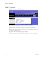
User Guide
Please Read
Important
Please read this entire guide. If this guide provides installation or operation
instructions, give particular attention to all safety statements included in this guide.
Notices
Trademark Acknowledgments
Cisco and the Cisco logo are trademarks or registered trademarks of Cisco and/or its
affiliates in the U.S. and other countries. A listing of Cisco's trademarks can be found
at www.cisco.com/go/trademarks.
The Wi-Fi Protected Setup mark is a mark of the Wi-Fi Alliance. Wi-Fi Protected
Setup is a trademark of the Wi-Fi Alliance.
Other third party trademarks mentioned are the property of their respective owners.
The use of the word partner does not imply a partnership relationship between
Cisco and any other company. (1009R)
Disclaimer
The maximum performance for wireless is derived from IEEE Standard 802.11
specifications. Actual performance can vary, including lower wireless network
capacity, data throughput rate, range and coverage. Performance depends on many
factors, conditions and variables, including distance from the access point, volume of
network traffic, building materials and construction, operating system used, mix of
wireless products used, interference and other adverse conditions.
Publication Disclaimer
Cisco Systems, Inc. assumes no responsibility for errors or omissions that may
appear in this publication. We reserve the right to change this publication at any
time without notice. This document is not to be construed as conferring by
implication, estoppel, or otherwise any license or right under any copyright or
patent, whether or not the use of any information in this document employs an
invention claimed in any existing or later issued patent.
Copyright
© 2009-2010, 2012 Cisco and/or its affiliates. All rights reserved. Printed in the United
States of America.
Information in this publication is subject to change without notice. No part of this
publication may be reproduced or transmitted in any form, by photocopy,
microfilm, xerography, or any other means, or incorporated into any information
retrieval system, electronic or mechanical, for any purpose, without the express
permission of Cisco Systems, Inc.
Notice to Installers
The servicing instructions in this notice are for use by qualified service personnel only. To reduce the
risk of electric shock, do not perform any servicing other than that contained in the operating
instructions, unless you are qualified to do so.
Notice à l’attention des installateurs de réseaux câblés
Les instructions relatives aux interventions d’entretien, fournies dans la présente notice, s’adressent
exclusivement au personnel technique qualifié. Pour réduire les risques de chocs électriques, n’effectuer
aucune intervention autre que celles décrites dans le mode d'emploi et les instructions relatives au
fonctionnement, à moins que vous ne soyez qualifié pour ce faire.
Mitteilung für CATV-Techniker
Die in dieser Mitteilung aufgeführten Wartungsanweisungen sind ausschließlich für qualifiziertes
Fachpersonal bestimmt. Um die Gefahr eines elektrischen Schlags zu reduzieren, sollten Sie keine
Wartungsarbeiten durchführen, die nicht ausdrücklich in der Bedienungsanleitung aufgeführt sind,
außer Sie sind zur Durchführung solcher Arbeiten qualifiziert.
Aviso a los instaladores de sistemas CATV
Las instrucciones de reparación contenidas en el presente aviso son para uso exclusivo por parte de
personal de mantenimiento cualificado. Con el fin de reducir el riesgo de descarga eléctrica, no realice
ninguna otra operación de reparación distinta a las contenidas en las instrucciones de funcionamiento, a
menos que posea la cualificación necesaria para hacerlo.
20080814_Installer800_Intl
Contents
IMPORTANT SAFETY INSTRUCTIONS
United States FCC Compliance
vii
x
CE Compliance
xii
About This Guide
xv
Chapter 1 Introducing the WAG310G
1
Benefits and Features .............................................................................................................. 2
What's on the Front Panel? ..................................................................................................... 3
What's on the Back Panel? ...................................................................................................... 5
About Wi-Fi Protected Setup ................................................................................................. 7
Chapter 2 Installing the Residential Gateway
9
Mounting the Residential Gateway ..................................................................................... 10
Connecting the Residential Gateway .................................................................................. 13
Chapter 3 Setup
15
Logging in to the Residential Gateway ............................................................................... 17
ADSL........................................................................................................................................ 18
Ethernet ................................................................................................................................... 33
Local Network ........................................................................................................................ 36
Setting System Date and Time ............................................................................................. 41
DDNS ....................................................................................................................................... 42
Advanced Routing ................................................................................................................. 44
PVC/VLAN Mapping ........................................................................................................... 46
Chapter 4 Wireless
49
Basic Settings .......................................................................................................................... 50
Wireless Network ..................................................................................................................... 51
Security .................................................................................................................................... 52
MAC Filter .............................................................................................................................. 57
Wi-Fi Protected Setup............................................................................................................ 59
3425-00669 Rev E
iii
Contents
Advanced Settings ................................................................................................................. 62
Chapter 5 Voice
65
About Voice ............................................................................................................................ 66
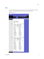
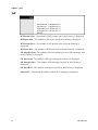
Info ........................................................................................................................................... 67
System...................................................................................................................................... 72
User1 or User2 ........................................................................................................................ 74
Chapter 6 Storage
81
Storage ..................................................................................................................................... 82
Chapter 7 Security Configuration
85
Firewall .................................................................................................................................... 86
Chapter 8 Access Restrictions
89
Internet Access Policy ........................................................................................................... 90
Chapter 9 Applications & Gaming
95
Single Port Forwarding ......................................................................................................... 96
Port Range Forwarding ......................................................................................................... 98
DMZ ....................................................................................................................................... 100
Port Range Triggering ......................................................................................................... 101
QoS (Quality of Service) ...................................................................................................... 103
Service.................................................................................................................................... 106
Chapter 10 Administration
109
Management ......................................................................................................................... 110
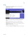
Log ......................................................................................................................................... 113
IP Ping ................................................................................................................................... 115
ATM F5 Loopback ............................................................................................................... 116
Backup ................................................................................................................................... 117
Factory Defaults ................................................................................................................... 118
Firmware Upgrade .............................................................................................................. 119
Reboot .................................................................................................................................... 120
Logging out of the Residential Gateway .......................................................................... 121
iv
3425-00669 Rev E
Contents
Chapter 11 Status
123
Internet .................................................................................................................................. 124
Local Network ...................................................................................................................... 126
Wireless ................................................................................................................................. 128
DSL Connection ................................................................................................................... 129
Bridges ................................................................................................................................... 131
ARP Table ............................................................................................................................. 132
Chapter 12 Troubleshooting
133
Computer Cannot Connect to the Internet ....................................................................... 134
Web Browser Prompts for Login Information ................................................................. 135
Computer Cannot Connect Wirelessly to the Network ................................................. 136
Modify the Advanced Settings .......................................................................................... 137
Chapter 13 Specifications
139
Interfaces ............................................................................................................................... 140
Environmental ...................................................................................................................... 141
Chapter 14 Customer Information
3425-00669 Rev E
143
v
IMPORTANT SAFETY INSTRUCTIONS
IMPORTANT SAFETY INSTRUCTIONS
1)
Read these instructions.
2)
Keep these instructions.
3)
Heed all warnings.
4)
Follow all instructions.
5)
Do not use this apparatus near water.
6)
Clean only with dry cloth.
7)
Do not block any ventilation openings. Install in accordance with the manufacturer's
instructions.
8)
Do not install near any heat sources such as radiators, heat registers, stoves, or other
apparatus (including amplifiers) that produce heat.
9)
Do not defeat the safety purpose of the polarized or grounding-type plug. A
polarized plug has two blades with one wider than the other. A grounding-type
plug has two blades and a third grounding prong. The wide blade or the third
prong are provided for your safety. If the provided plug does not fit into your
outlet, consult an electrician for replacement of the obsolete outlet.
10)
Protect the power cord from being walked on or pinched particularly at plugs,
convenience receptacles, and the point where they exit from the apparatus.
11)
Only use attachments/accessories specified by the manufacturer.
12)
Use only with the cart, stand, tripod, bracket, or table specified by the
manufacturer, or sold with the apparatus. When a cart is used, use caution
when moving the cart/apparatus combination to avoid injury from
tip-over.
13)
Unplug this apparatus during lightning storms or when unused for long periods of
time.
14)
Refer all servicing to qualified service personnel. Servicing is required when the
apparatus has been damaged in any way, such as a power-supply cord or plug is
damaged, liquid has been spilled or objects have fallen into the apparatus, the
apparatus has been exposed to rain or moisture, does not operate normally, or has
been dropped.
Power Source Warning
A label on this product indicates the correct power source for this product. Operate this product only
from an electrical outlet with the voltage and frequency indicated on the product label. If you are
uncertain of the type of power supply to your home or business, consult your service provider or your
local power company.
The AC inlet on the unit must remain accessible and operable at all times.
Ground the Product
WARNING: Avoid electric shock and fire hazard! If this product connects to coaxial
cable wiring, be sure the cable system is grounded (earthed). Grounding provides
some protection against voltage surges and built-up static charges.
3425-00669 Rev E
vii
IMPORTANT SAFETY INSTRUCTIONS
Protect the Product from Lightning
In addition to disconnecting the AC power from the wall outlet, disconnect the signal inputs.
Verify the Power Source from the On/Off Power Light
When the on/off power light is not illuminated, the apparatus may still be connected to the power
source. The light may go out when the apparatus is turned off, regardless of whether it is still plugged
into an AC power source.
Eliminate AC Mains Overloads
WARNING: Avoid electric shock and fire hazard! Do not overload AC mains, outlets,
extension cords, or integral convenience receptacles. For products that require battery
power or other power sources to operate them, refer to the operating instructions for
those products.
Provide Ventilation and Select a Location
Remove all packaging material before applying power to the product.
Do not place entertainment devices (such as VCRs or DVDs), lamps, books, vases with liquids, or
other objects on top of this product.
Do not block ventilation openings.
Do not place this apparatus on a bed, sofa, rug, or similar surface.
Do not place this apparatus on an unstable surface.
Do not install this apparatus in an enclosure, such as a bookcase or rack, unless the installation
provides proper ventilation.
Protect from Exposure to Moisture and Foreign Objects
WARNING: Avoid electric shock and fire hazard! Do not expose this product to
dripping or splashing liquids, rain, or moisture. Objects filled with liquids, such as
vases, should not be placed on this apparatus.
WARNING: Avoid electric shock and fire hazard! Unplug this product before cleaning.
Do not use a liquid cleaner or an aerosol cleaner. Do not use a magnetic/static cleaning
device (dust remover) to clean this product.
WARNING: Avoid electric shock and fire hazard! Never push objects through the
openings in this product. Foreign objects can cause electrical shorts that can result in
electric shock or fire.
Service Warnings
WARNING: Avoid electric shock! Do not open the cover of this product. Opening or
removing the cover may expose you to dangerous voltages. If you open the cover, your
warranty will be void. This product contains no user-serviceable parts.
viii
3425-00669 Rev E
IMPORTANT SAFETY INSTRUCTIONS
Check Product Safety
Upon completion of any service or repairs to this product, the service technician must perform safety
checks to determine that this product is in proper operating condition.
Protect the Product When Moving It
Always disconnect the power source when moving the apparatus or connecting or disconnecting
cables.
Telephone Equipment Notice
When using your telephone equipment, basic safety precautions should always be followed to reduce
the risk of fire, electric stock and injury to persons, including the following:
1. Do not use this product near water, for example, near a bath tub, wash bowl, kitchen sink or laundry
tub, in a wet basement or near a swimming pool.
2. Avoid using a telephone (other than a cordless type) during an electrical storm. There may be a
remote risk of electric shock from lightning.
3. Do not use the telephone to report a gas leak in the vicinity of the leak.
CAUTION: To reduce the risk of fire, use only No. 26 AWG or larger
telecommunication line cord.
SAVE THESE INSTRUCTIONS
20090915_Modem No Battery_Safety
3425-00669 Rev E
ix
United States FCC Compliance
United States FCC Compliance
This device has been tested and found to comply with the limits for a Class B digital device,
pursuant to part 15 of the FCC Rules. These limits are designed to provide reasonable
protection against such interference in a residential installation. This equipment generates,
uses, and can radiate radio frequency energy. If not installed and used in accordance with the
instructions, it may cause harmful interference to radio communications. However, there is
no guarantee that interference will not occur in a particular installation. If this equipment
does cause harmful interference to radio or television reception, which can be determined by
turning the equipment OFF and ON, the user is encouraged to try to correct the interference
by one or more of the following measures:
Reorient or relocate the receiving antenna.
Consult the service provider or an experienced radio/television technician for help.
Increase the separation between the equipment and receiver.
Connect the equipment into an outlet on a circuit different from that to which the
receiver is connected.
Any changes or modifications not expressly approved by Cisco Systems, Inc., could void the
user's authority to operate the equipment.
The information shown in the FCC Declaration of Conformity paragraph below is a
requirement of the FCC and is intended to supply you with information regarding the FCC
approval of this device. The phone numbers listed are for FCC-related questions only and not
intended for questions regarding the connection or operation for this device. Please contact your
service provider for any questions you may have regarding the operation or installation of this device.
Declaration of Conformity
This device complies with Part 15 of FCC
Rules. Operation is subject to the following
two conditions: 1) the device may not cause
harmful interference, and 2) the device must
accept any interference received, including
interference that may cause undesired
operation.
Wireless-G ADSL2+ Gateway with VoIP
Model WAG310G
Manufactured by:
Cisco Systems, Inc.
5030 Sugarloaf Parkway
Lawrenceville, Georgia 30044 USA
Telephone: 678-277-1120
Canada EMI Regulation
This Class B digital apparatus complies with Canadian ICES-003.
Cet appareil numérique de la class B est conforme à la norme NMB-003 du Canada.
RF Exposure Statements
Note: This transmitter must not be co-located or operated in conjunction with any other
antenna or transmitter. This equipment should be installed and operated with a minimum
distance of 7.9 inches (20 cm) between the radiator and your body.
x
3425-00669 Rev E
United States FCC Compliance
US
This system has been evaluated for RF exposure for humans in reference to ANSI C 95.1
(American National Standards Institute) limits. The evaluation was based in accordance with
FCC OET Bulletin 65C rev 01.01 in compliance with Part 2.1091 and Part 15.27. The minimum
separation distance from the antenna to general bystander is 7.9 inches (20 cm) to maintain
compliance.
Canada
This system has been evaluated for RF exposure for humans in reference to Canada Health
Code 6 (2009) limits. The evaluation was based on evaluation per RSS-102 Rev 4. The
minimum separation distance from the antenna to general bystander is 7.9 inches (20 cm) to
maintain compliance.
20100527 FCC DSL_Domestic
3425-00669 Rev E
xi
CE Compliance
CE Compliance
Declaration of Conformity with Regard to the EU Directive 1999/5/EC
(R&TTE Directive)
This declaration is only valid for configurations (combinations of software, firmware and
hardware) supported or provided by Cisco Systems for use within the EU. The use of
software or firmware not supported or provided by Cisco Systems may result in the
equipment no longer being compliant with the regulatory requirements.
xii
3425-00669 Rev E
CE Compliance
Note: The full declaration of conformity for this product can be found in the Declarations of
Conformity and Regulatory Information section of the appropriate product hardware
installation guide, which is available on Cisco.com.
The following standards were applied during the assessment of the product against the
requirements of the Directive 1999/5/EC:
Radio: EN 300 328
EMC: EN 301 489-1 and EN 301 489-17
Safety: EN 60950 and EN 50385
The CE mark and class-2 identifier are affixed to the product and its packaging. This product
conforms to the following European directives:
-1999/5/EC
National Restrictions
This product is for indoor use only.
France
For 2.4 GHz, the output power is restricted to 10 mW EIRP when the product is used
outdoors in the band 2454 - 2483,5 MHz. There are no restrictions when used in other parts of
the 2,4 GHz band. Check http://www.arcep.fr/ for more details.
Pour la bande 2,4 GHz, la puissance est limitée à 10 mW en p.i.r.e. pour les équipements
utilisés en extérieur dans la bande 2454 - 2483,5 MHz. Il n'y a pas de restrictions pour des
utilisations dans d'autres parties de la bande 2,4 GHz. Consultez http://www.arcep.fr/ pour
de plus amples détails.
Italy
This product meets the National Radio Interface and the requirements specified in the
National Frequency Allocation Table for Italy. Unless this wireless LAN product is operating
within the boundaries of the owner's property, its use requires a “general authorization.”
Please check http://www.comunicazioni.it/it/ for more details.
Questo prodotto è conforme alla specifiche di Interfaccia Radio Nazionali e rispetta il Piano
Nazionale di ripartizione delle frequenze in Italia. Se non viene installato all 'interno del
proprio fondo, l'utilizzo di prodotti Wireless LAN richiede una “Autorizzazione Generale”.
Consultare http://www.comunicazioni.it/it/ per maggiori dettagli.
Latvia
The outdoor usage of the 2.4 GHz band requires an authorization from the Electronic
Communications Office. Please check http://www.esd.lv for more details.
2,4 GHz frekvenču joslas izmantošanai ārpus telpām nepieciešama atļauja no Elektronisko
sakaru direkcijas. Vairāk informācijas: http://www.esd.lv.
Note: The regulatory limits for maximum output power are specified in EIRP. The EIRP level
of a device can be calculated by adding the gain of the antenna used (specified in dBi) to the
output power available at the connector (specified in dBm).
3425-00669 Rev E
xiii
CE Compliance
Antennas
Use only the antenna supplied with the product.
20090312 CE_Gateway
xiv
3425-00669 Rev E
About This Guide
About This Guide
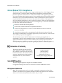
Introduction
This installation and operation guide applies to the WAG310G series residential
gateway. The WAG310G series residential gateway connects to the DSL network in
your home to deliver data, video, voice, and wired (Ethernet) or wireless gateway
capabilities all from one device. Use this guide to install the residential gateway in
your home.
Purpose
This document provides the information you need to install and operate the
WAG310G series residential gateway.
Audience
This guide is written for subscribers who have purchased a residential gateway and
want to experience high-speed Internet and high-quality digital telephone service
can use this guide for background information and basic operation.
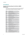
Document Version
This is the fifth formal release of this document. In addition to minor text and
graphic changes, the following table provides the technical changes to this
document.
Description
See Topic
Changes include updates to screens and
descriptions for the user setup.
See Setup (on page 15).
3425-00669 Rev E
xv
1 Chapter 1
Introducing the WAG310G
Introduction
Thank you for choosing the Cisco® Wireless-G ADSL2+ Gateway with
VoIP (WAG310G). The WAG310G combines an ADSL/2/2+ modem,
1 Ethernet WAN port, Wireless-G access point, 4-port Ethernet switch,
USB host port, and an analog telephone adapter (ATA) with 2 FXS
ports and 1 FXO port. The WAG310G can be connected to the Public
Switched Telephone Network (PSTN), which is the network that
traditional phone service uses, so you can make calls using the
traditional service or Voice over IP (VoIP).
You can also use the Residential Gateway to share resources such as
computers and storage. Various security features help to protect your
data and your privacy while you are online. Security features include
WPA2 security, a Stateful Packet Inspection (SPI) firewall, and NAT
technology. Configuring the Residential Gateway is easy using the
provided browser-based utility.
The WAG310G meets the needs of a variety of deployment
architectures with both an Ethernet WAN interface or a high-speed
ADSL/2/2+ interface supporting up to 8 PVCs and support for
advanced features like QoS and IGMP to help create the framework to
enable data, voice and IP video services.
In This Chapter
3425-00669 Rev E
Benefits and Features ............................................................................. 2
What's on the Front Panel? .................................................................... 3
What's on the Back Panel? ..................................................................... 5
About Wi-Fi Protected Setup ................................................................ 7
1
Chapter 1 Introducing the WAG310G
Benefits and Features
The WAG310G offers the following benefits and features:
Full routing functionality. The residential gateway router provides broadband
transfer speeds available between your home network and the service provider's
network for multi-user sharing. The high-performance router distributes data
seamlessly to all devices in the network without a noticeable effect to
performance or speed.
True firewall capability. The residential gateway firewall includes both
standard NAT/PAT security and Stateful Packet inspection to defend against
external attacks.
High-quality data, voice, and IPTV services. The residential gateway combines
an ADSL2+, 4-port Ethernet switch, bridge and router functionality with VoIP
and Wi-Fi into one integrated platform
Compact design. The residential gateway is compact enough to sit on a desktop
and versatile enough to be wall mounted in an out of the way location. The
residential gateway can also stand vertically.
Flexible networking. The residential gateway combines a variety of home
networking technologies in one box: Ethernet, 802.11 b/g wireless, and VoIP.
-
Ethernet. Ethernet is a network standard for data transmission using either
coaxial or twisted pair cable over a LAN (local area network). The
information can be transmitted at speeds of 10 to 100 Mbps. If the home or
office is wired for Ethernet, use one of the four LAN interfaces on the
residential gateway to create a broadband network.
-
802.11 b/g Wireless. The residential gateway includes an integrated wireless
access point that allows you to roam wirelessly throughout your home or
office.
ADSL high speed data access. Asymmetric Digital Subscriber Line (ADSL)
provides high-access transmission speeds for delivery of video, voice, and data
services to homes over ordinary copper telephone wire.
2
3425-00669 Rev E
What's on the Front Panel?
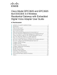
What's on the Front Panel?
The front panel of your residential gateway provides LED status indicators that
indicate the operational state of your gateway. Refer to the following diagram for a
description of the front panel.
1
Power (Green/Red)—The Power LED lights up when the residential gateway is
powered on. It flashes during during bootup and flash test. The LED becomes
red during a malfunction.
2
Ethernet LAN 1-4 (Green)—These numbered LEDs, corresponding with the
numbered Ethernet ports on the residential gateway’s back panel, serve two
purposes. If the LED is solid, the residential gateway is connected to a device
through that port. It flashes to indicate network activity over that port.
3
Ethernet WAN/LAN 5 (Green—The WAN/LAN 5 LED corresponds with the
WAN/LAN5 port and serves two purposes. If the LED is solid, the residential
gateway is successfully connected to a device through that port. It flashes to
indicate network activity over that port.
4
Wireless Activity (Green)—The Activity LED lights up when the wireless
feature is enabled. It flashes when the residential gateway is sending or receiving
data over the wireless network.
5
Wireless Security (Green/Red)—The Security LED lights up when wireless
security is enabled. It flashes during the Wi-Fi Protected Setup process. The LED
becomes red when wireless security is not configured (off).
Note: Some countries require by law for wireless networks to be secured. Cisco is
not responsible for users who do not adhere to country-specific regulations.
Contact your service provider to find out what your country requires.
6
USB (Green)—The USB LED lights up when the residential gateway is connected
to a device through the USB port. It flashes to indicate USB activity.
3425-00669 Rev E
3
Chapter 1 Introducing the WAG310G
7
Phone 1-2 (Green)— The Phone 1 or 2 LED will be OFF if no service has been
configured and registered based on the voice setting for the corresponding
phone port. It will be ON if service has been configured and registered for the
corresponding phone port. It flashes when the phone is being used.
8
Line (Green)—The Line LED will flash when it is connected to the Public
Switched Telephone Network (PSTN) through the Line port and is being used.
Otherwise it’ll be OFF.
9
DSL (Green)—The DSL LED lights up when there is a DSL connection. It flashes
when the residential gateway is establishing the ADSL connection.
10 Internet (Green/Red)—The Internet LED lights up when the residential gateway
is connected to the Internet. It flashes to indicate network activity over the
Internet port. The LED becomes red when the Internet connection fails.
4
3425-00669 Rev E
What's on the Back Panel?
What's on the Back Panel?
The back panel of your residential gateway provides ports, power, and reset
mechanisms. Refer to the following diagram for a description of the back panel.
1
DSL—The DSL port connects to the ADSL line.
2
Line—The Line port connects to either the voice connection on the DSL
microfilter or wall jack.
3
Phone 1-2— The Phone ports connect standard analog telephones to the
residential gateway. The Phone 1 or 2 LED on the front panel lights up when a
phone is connected to the corresponding port on the residential gateway’s back
panel. It flashes when the phone is being used.
4
USB—The USB port connects to a USB storage device, such as a USB hard drive
or flash disk.
5
Ethernet WAN/LAN5—The WAN/LAN5 port can act as a Wide Area Network
(WAN) or Local Area Network (LAN) port. As a WAN port, it connects to a
broadband modem. As a LAN port, it connects to a wired computer or other
Ethernet network device.
6
Ethernet LAN 1-4—These Ethernet ports (1, 2, 3, 4) connect the residential
gateway to wired computers and other Ethernet network devices.
7
Power Switch—Use this switch to power on or off the residential gateway.
8
Power—The Power port is where you will connect the 12v/2A power adapter
that is included in the box.
3425-00669 Rev E
5
Chapter 1 Introducing the WAG310G
9
Reset—There are two ways to reset the residential gateway’s settings to factory
defaults. Either press and hold the Reset button for approximately 30 seconds, or
restore the defaults from the Administration > Factory Defaults screen of the
residential gateway’s web-based utility.
Note: The reset feature removes all previous configuration settings. You will
need to manually configure settings that are lost when you perform a reset.
6
3425-00669 Rev E
About Wi-Fi Protected Setup
About Wi-Fi Protected Setup
If you have a client device, such as a wireless adapter, that supports Wi-Fi Protected
Setup, then you can use Wi-Fi Protected Setup to automatically configure wireless
security for your wireless network(s).
Notes:
Wi-Fi Protected Setup can only be used for the default wireless network. (The
residential gateway supports up to four wireless networks. The other three can
be configured using the residential gateway’s web-based utility.)
Wi-Fi Protected Setup configures one client device at a time. Repeat the
instructions for each client device that supports Wi-Fi Protected Setup.
Method 1
Use this method if your client device has a Wi-Fi Protected Setup button.
1
Click or press the Wi-Fi Protected Setup button on the client device. (If Wi-Fi
Protected Setup is an on-screen option, then select it.)
2
Click the Wi-Fi Protected Setup button on the top panel of the residential
gateway.
3
After the client device has been configured, refer back to your client device or its
documentation for further instructions.
Method 2
Use this method if your client device has a Wi-Fi Protected Setup PIN number.
1
Access the residential gateway’s web-based utility.
2
Click the Wireless tab.
3
Click the Wi-Fi Protected Setup tab.
4
Enter the client PIN number in the PIN field on this screen (the residential
gateway’s Wi-Fi Protected Setup screen).
5
Click Register.
Method 3
Use this method if your client device asks for the residential gateway’s PIN number.
1
Enter the PIN number listed on the label on the bottom of the residential
gateway.
2
After the client device has been configured, refer back to your client device or its
documentation for further instructions.
3425-00669 Rev E
7
Chapter 1 Introducing the WAG310G
8
3425-00669 Rev E
2 Chapter 2
Installing the Residential
Gateway
Introduction
You have two options to physically install the residential gateway. The
first option is to place the residential gateway horizontally on a
surface. The second option is to mount the residential gateway on a
wall.
In This Chapter
3425-00669 Rev E
Mounting the Residential Gateway.................................................... 10
Connecting the Residential Gateway ................................................. 13
9
Chapter 2 Installing the Residential Gateway
Mounting the Residential Gateway
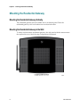
Mounting the Residential Gateway Vertically
The residential gateway has four rubber feet on its bottom panel. Place the
residential gateway on a level surface near an electrical outlet.
Mounting the Residential Gateway to the Wall
To safely wall-mount the residential gateway, the side panel with the antenna must
face upward in one of the following configurations illustrated:
10
3425-00669 Rev E
Mounting the Residential Gateway
The residential gateway has four wall-mount slots on its bottom panel. Two screws
are needed to mount the residential gateway.
3425-00669 Rev E
11
Chapter 2 Installing the Residential Gateway
The following illustration shows the location and dimensions of the wall-mounting
slots on the bottom of the residential gateway. Use the information on this page as a
guide for mounting your residential gateway to the wall.
Notes:
Mounting hardware illustrations are not true to scale.
Cisco is not responsible for damages incurred by insecure wall-mounting
hardware.
Follow these instructions:
12
1
Determine where you want to mount the residential gateway. Make sure that the
wall you use is smooth, flat, dry, and sturdy. Also make sure the location is
within reach of an electrical outlet.
2
Drill two holes into the wall. Make sure the holes are 54 mm (21. 3 inches) apart.
3
Insert a screw into each hole and leave 2 mm (0.8 inches) below the head
exposed.
4
Maneuver the residential gateway so two of the wall-mount slots line up with
the two screws.
5
Place the wall-mount slots over the screws and slide the residential gateway
down until the screws fit snugly into the wall-mount slots.
3425-00669 Rev E
Connecting the Residential Gateway
Connecting the Residential Gateway
Make sure that you have the following package contents:
WAG310G
RJ-45 Ethernet cable
RJ-11 phone cable
Power Adapter
One analog touchtone telephone, if configuring VoIP service
Access to a PSTN connection (wall jack).
Perform the following steps to connect the WAG310G.
1
Insert a standard RJ-11 phone cable (included) into the DSL port and connect the
other end to the PSTN wall jack.
2
(Optional) Connect a PC or other Ethernet device to the LAN port using a
standard RJ-45 Ethernet cable.
3
Insert a standard RJ-11 telephone cable into the PHONE 1 (FXS) port and connect
the other end to an analog touchtone telephone.
4
(Optional) You can connect the PHONE 2 (FXS) port to a second analog
telephone or a fax machine.
Note: To prevent an invalid connection to the circuit switched Telco network, do
not connect an RJ-11 telephone cable from the PHONE 1 (or PHONE 2) port on
the WAG310G to the wall jack.
5
Connect the RJ-11 phone cable (included) to the LINE (FXO) port and connect the
other end to your telephone wall jack.
6
Connect the included power adapter to the WAG310G power port, and then
plug the power adapter into an electrical outlet. The power LED on the front
panel will light up as soon as the device powers on.
7
Power on the WAG310G.
8
Follow the instructions in your owner's manual for your PC or laptop to activate
the wireless connection.
Note: A wireless connection requires a wireless-enabled notebook or a computer
with an 802.11b/g wireless network adapter installed.
3425-00669 Rev E
13
3 Chapter 3
Setup
Introduction
This chapter provides information for using the web-based utility to
configure ADSL, Ethernet, and Local Network connections.
You can access the utility via a web browser on a computer connected
to the residential gateway.
The web-based utility has these main tabs: Setup, Wireless, Voice,
Storage, Security, Access Restrictions, Applications & Gaming,
Administration, and Status. Additional tabs will be available after you
click one of the main tabs.
This chapter focuses on the configuring the parameters that are
accessed via the Setup tab.
Important: The web-based utility pages and the examples shown in
this section are for illustration purposes only. Your pages may differ
from the pages shown in this guide. The pages shown in this guide
also represent the default values for the device.
Notes:
If you are not familiar with the network configuration procedures
detailed in this section, contact your service provider before you
attempt to change any of the residential gateway default settings.
If your service provider supplied you with the residential gateway,
then it may be pre-configured for you, and you will not need to
make any changes. Contact your service provider for more
information.
For New Zealand residents, refer to the note under PPPoA (RFC
2364).
3425-00669 Rev E
15
Chapter 3 Setup
In This Chapter
16
Logging in to the Residential Gateway.............................................. 17
ADSL ...................................................................................................... 18
Ethernet .................................................................................................. 33
Local Network ....................................................................................... 36
Setting System Date and Time ............................................................ 41
DDNS...................................................................................................... 42
Advanced Routing ................................................................................ 44
PVC/VLAN Mapping .......................................................................... 46
3425-00669 Rev E
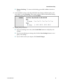
Logging in to the Residential Gateway
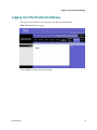
Logging in to the Residential Gateway
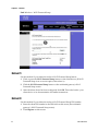
Complete the following steps to access the web-based utility.
Note: If the residential gateway was supplied by your service provider, then it may
restrict access to the web-based utility. Contact your service provider for the login
information.
1
Launch the web browser on your computer.
2
Type 192.168.1.1 in the URL Address field. This value is the residential gateway's
default IP address.
3
Press Enter. A login screen appears.
4
Is this the first time you have opened the web-based utility?
If yes, type admin in the User name and Password fields. (You can change
the default values to a new user name and password from the
Administration tab’s Management screen.)
If no, enter the user name and password you established previously.
5
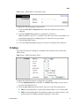
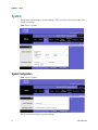
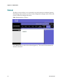
Click OK to continue. The web-based utility opens. Upon logging into the webbased utility, the Basic Setup screen appears. There are two views available, Basic
and Advanced. The default view is Basic. To display the Advanced View, click
Advanced View. To return to the Basic View, click Basic View.
6
To continue setup, go to the section applicable for your desired configuration:
3425-00669 Rev E
ADSL (on page 18)
Ethernet (on page 33).
17
Chapter 3 Setup
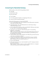
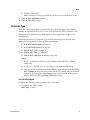
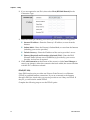
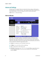
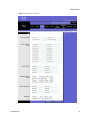
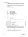
ADSL
From the ADSL screen you can setup Internet configuration parameters.
Path: Setup > ADSL
Note: There are two views available, Basic and Advanced. The default view is Basic.
To display the Advanced View, click Advanced View. To return to the Basic View,
click Basic View.
PVC Connection
The residential gateway supports up to eight Private Virtual Circuit (PVC)
connections. The default PVC addresses are 0/35, 8/35, 0/43, 0/51, 0/59, 8/43, 8/51,
and 8/59.
Notes:
PVCs are layer 2 (physical and link), while WAN connections are layer 3,
meaning IP and Point-to-Point (PPP) connections.
Each PVC supports multiple connections. For each PVC, you can configure one
IP connection and up to four PPP over Ethernet (PPPoE) connections.
18
3425-00669 Rev E
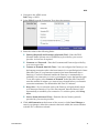
ADSL
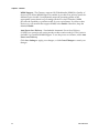
Path: Setup > ADSL (Basic or Advanced View)
Complete the following steps to setup a PVC.
1
From the Select PVC Connection field, select the connection you want to
configure.
2
Check the Enable Now checkbox to enable this connection.
Note: By default, only PVC 1 is enabled. The other seven PVCs are disabled. You
must enable them before configuring layer 3 connections on top of them.
3
Click the Save PVC button.
4
Go to the Connection Type (on page 21) section to configure this connection.
VC Settings
The Virtual Circuit (VC) settings are available in the Advanced View link of the
ADSL screen.
Path: Setup > ADSL (Advanced View)
Complete the following steps to configure the VC settings.
1
For the Multiplexing field, select LLC or VCMUX, depending on your service
provider. The default is LLC.
2
From the QoS Type drop-down menu, select one of the following options:
3425-00669 Rev E
CBR (Constant Bit Rate) to specify fixed bandwidth for voice or data traffic
UBR (Unspecified Bit Rate) for applications that are not time-sensitive, such
Internet access for WEB browising, loading files, and e-mail
19
Chapter 3 Setup
VBR_rt or VBR_nrt. VBR (Variable Bit Rate) is used for bursty traffic and
bandwidth-sharing with other applications. VBR_rt (real time) is more timesensitive than VBR_nrt (non-real time), and VBR_rt is typically used for voice
and video traffic.
Notes:
If the QoS Type setting is CBR, then the Scr Rate and Max Burst Size settings
are not configurable.
If the QoS Type setting is UBR, then the Pcr Rate, Scr Rate, and Max Burst
Size settings are not configurable.
If the QoS Type setting is VBR-rt or VBR-nrt, set the appropriate Pcr Rate,
Scr Rate, and Max Burst Size values.
Note: The values entered are interpreted as ATM Cells per second (cps).
3
If required by your service provider, enter a rate in the PCR Rate field.
Note: The Peak Cell Rate (PCR) is the maximum allowable rate at which cells can
be transported. Enter the rate in the field (if required by your service provider).
4
If required by your service provider, enter a rate in the SCR Rate field.
Note: The Sustainable Cell Rate (SCR) sets the average cell rate that can be
transmitted. The SCR value is normally less than the PCR value. Enter the rate in
the field ( provider).
5
For the Max Burst Size, enter the number of contiguous (ATM) cells allowed to
be send in one burst.
6
For the Autodetect, select Enable to have the settings automatically entered, or
select Disable to enter the values manually.
Note: Autodetect requires a PVC value which is part of the “pre-configured
range” of default PVCs being 0/35, 8/35, 0/43, 0/51, 0/59, 8/43, 8/51, and
8/59. Other values will not be autodetected and should be entered manually.
7
Enter the settings provided by your service provider for each of the following
Virtual Circuit settings:
8
VCI (Virtual Channel Identifier).
For the DSL Modulation, select the appropriate mode from the list of available
options; then, click Save Modulation to save the modulation setting.
20
VPI (Virtual Path Identifier)
MultiMode
T1.413
G.DMT
G.lite
ADSL2
ADSL2 (Annex L)
ADSL2 (Annex M)
ADSL2+
3425-00669 Rev E
ADSL
9
ADSL2+ (Annex M).
Note: Contact your service provider if you are not sure which mode to use.
Click the Save Modulation button.
10 Click the Save PVC button.
Connection Type
From the ADSL screen (Basic or Advanced View), the Connection Type selected,
whether an Internet Protocol (IP) or Point-to-Point Protocol (PPP) connection, will
determine what additional IP or PPP settings will be required to complete your
configuration.
Determine the desired Connection Type from the following list of options; then
proceed to the applicable section for setup instructions:
IPoE (RFC2684 Bridged) (on page 21)
IPoA (RFC2684 Routed) (on page 23)
PPPoE (RFC 2516) (on page 24)
PPPoA (RFC 2364) (on page 26)
PPPoE (RFC 2364)-New Zealand (on page 28)
Notes:
For IP-over-Ethernet (IPoE), you can configure either DHCP or static IP
addressing.
For IP-over-ATM (IPoA), you can configure only static IP addressing.
Once an IP/PPP connection has been added it can be selected from the Select
PVC Connection drop-down box where the IP/PPP setting may be modified
and saved by clicking the Save Settings button at the bottom of the page or
may be deleted by clicking Delete Connection button.
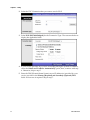
IPoE (RFC2684 Bridged)
Complete the following steps to add an IPoE connection.
1
3425-00669 Rev E
Navigate to the ADSL screen.
Path: Setup > ADSL
21
Chapter 3 Setup
22
2
Select the PVC Connection that you want to use for IPoE.
3
Select IPoE (RFC2684 Bridged) for the Connection Type. The screen refreshes to
display the applicable fields.
4
If your service provider says you are connecting through a dynamic IP address,
select the Obtain an IP Address Automatically option; then, continue with step
4. Otherwise, skip to step 5.
5
Enter the DNS (Domain Name System) server IP address(es) provided by your
service provider in the Primary (Required) and Secondary (Optional) DNS
fields. At least one is required. Skip to step 7.
3425-00669 Rev E
ADSL
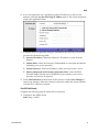
6
If you are required to use a permanent (static) IP address to connect to the
Internet, select the Use the following IP Address option. The screen refreshes to
display the applicable fields.
7
Complete the following fields using the information provided by your service
provider for the following fields:
8
Internet IP Address—Enter the Gateway’s IP address, as seen from the
Internet.
Subnet Mask—Enter the Gateway’s Subnet Mask, as seen from the Internet
(including your service provider).
Default Gateway—Enter the IP address of the service provider’s server.
Primary (Required) and Secondary (Optional) DNS—Enter the DNS
(Domain Name System) server IP address(es) provided by your service
provider. At least one is required.
Click Add Connection at the bottom of the screen (or click Cancel Changes to
cancel your changes). After the connection has been added, the screen refreshes
with the PVC connection selected.
IPoA (RFC2684 Routed)
Complete the following steps to add an IPoA connection.
1
3425-00669 Rev E
Navigate to the ADSL screen.
Path: Setup > ADSL
23
Chapter 3 Setup
2
If you are required to use IPoA, then select IPoA (RFC2684 Routed) for the
Connection Type.
3
Enter the values provided by your service provider for the following fields:
4
Internet IP Address—Enter the Gateway’s IP address, as seen from the
Internet.
Subnet Mask—Enter the Gateway’s Subnet Mask, as seen from the Internet
(including your service provider).
Default Gateway—Enter the IP address of the service provider’s server.
Primary (Required) and Secondary (Optional) DNS—Enter the DNS
(Domain Name System) server IP address(es) provided by your service
provider. At least one is required.
Click Add Connection at the bottom of the screen (or click Cancel Changes to
cancel your changes). After the connection has been added, the screen refreshes
with the PVC connection selected.
PPPoE (RFC 2516)
Some DSL-based service providers use Point-to-Point Protocol over Ethernet
(PPPoE) to establish Internet connections. If you are connected to the Internet
through a DSL line, check with your service provider to see if they use PPPoE. If
they do, you will need to enable PPPoE.
Complete the following steps to use the PPPoE option.
24
3425-00669 Rev E
ADSL
1
Navigate to the ADSL screen.
Path: Setup > ADSL
2
Select PPPoE from the Connection Type drop-down menu.
3
Enter the values in the following fields:
4
3425-00669 Rev E
Primary (Required) and Secondary (Optional) DNS—Enter the DNS
(Domain Name System) server IP address(es) provided by your service
provider. At least one is required.
Username and Password—Enter the Username and Password provided by
your service provider.
Connect on Demand: Max Idle Time—You can configure the Gateway to cut
the Internet connection after it has been inactive for a specified period of time
(Max Idle Time). If your Internet connection has been terminated due to
inactivity, Connect on Demand enables the Gateway to automatically reestablish your connection as soon as you attempt to access the Internet again.
To use this option, select Connect on Demand. In the Max Idle Time field,
enter the number of minutes you want to have elapsed before your Internet
connection terminates. The default Max Idle Time is 5 minutes.
Keep Alive—If you select this option, the Gateway will periodically check
your Internet connection. If you are disconnected, then the Gateway will
automatically re-establish your connection. To use this option, select Keep
Alive.
Service Name (Advanced View)—Enter the Service Name (optional)
provided by your service provider.
Click Add Connection at the bottom of the screen (or click Cancel Changes to
cancel your changes). After the connection has been added, the screen refreshes
with the PVC connection selected.
25
Chapter 3 Setup
PPPoA (RFC 2364)
Some DSL-based service providers use Point-to-Point Protocol over ATM (PPPoA) to
establish Internet connections. If you are connected to the Internet through a DSL
line, check with your service provider to see if they use PPPoA. If they do, you will
have to enable PPPoA.
Complete the following steps to use the PPPoA option.
1
Navigate to the ADSL screen.
Path: Setup > ADSL
2
Select PPPoA from the Connection Type drop-down menu.
3
Enter the Basic Settings values in the following fields:
26
Gateway Probing—This feature provides the capability for the residential
gateway to detect if a loss of IP connectivity occurs. Select Enable if you want
the WAG310G to probe the WAN default gateway at certain intervals
(specified by the user) by sending an ARP request and it will look for an ARP
reply from the server. Once a loss in IP connectivity is detected (i.e., no ARP
reply received), the WAG310G will initiate a request for a new DHCP lease.
–
Probing Using Unicast—Select Enable to send unicast ARP requests to
the server. Select Disable to send out broadcast ARP.
–
Probing Interval—Enter the number of seconds to wait after detecting
the loss of connectivity before probing sending an ARP request.
Primary (Required) and Secondary (Optional) DNS—Enter the DNS
(Domain Name System) server IP address(es) provided by your service
provider. At least one is required.
Username and Password—Enter the Username and Password provided by
your service provider.
3425-00669 Rev E
ADSL
4
3425-00669 Rev E
Connect on Demand: Max Idle Time—You can configure the Gateway to cut
the Internet connection after it has been inactive for a specified period of time
(Max Idle Time). If your Internet connection has been terminated due to
inactivity, Connect on Demand enables the Gateway to automatically reestablish your connection as soon as you attempt to access the Internet again.
To use this option, select Connect on Demand. In the Max Idle Time field,
enter the number of minutes you want to have elapsed before your Internet
connection terminates. The default Max Idle Time is 5 minutes.
Keep Alive—If you select this option, the Gateway will periodically check
your Internet connection. If you are disconnected, then the Gateway will
automatically re-establish your connection. To use this option, select Keep
Alive.
Service Name (Advanced View)—Enter the Service Name (optional)
provided by your service provider.
Enter the Advanced View settings values in the following fields:
NAT—To use Network Address Translation, keep the default Enabled.
Otherwise, select Disabled.
IGMP Forwarding—Select Enabled, if you want to allow multicast traffic
through the Router for your multimedia application devices. Otherwise, keep
the default, Disabled.
Dedicate The Connection To Voice (FXS1/FXS2)—Select Enabled, if you
want to use this connection for FXS1/FXS2 outbound phone calls. (You can
enable this option for only one Internet connection.) Otherwise, keep the
default, Disabled.
VLAN ID Mark—Enter the 802.1Q VLAN ID Mark to be used on traffic to
and from the interface associated with this connection. The default is -1,
which indicates that the VLAN connection is untagged. Range is 0 through
4095.
802.1p Mark—Enter the 802.1p (Ethernet priority) Mark to be used on traffic
sent out on this connection. A value of -1 indicates no change from the
incoming packet. The default is -1.
Override Ethernet Priority—If this option is disabled and the 802.1p Mark is
specified, then the 802.1p Mark is applied only to packets of priority 0. If this
option is enabled and the 802.1p Mark is specified, then the 802.1p Mark is
applied to all packets on this connection. To enable this option, select the
check box. Otherwise, leave the check box blank.
RIP Recv Packet Version—Select the Routing Information Protocol (RIP)
version you want to use: RIP off, RIPv1, or RIPv2.
Domain Name—Enter the Domain Name for this connection. The DNS
proxy will compare Domain Names to choose the connection that will send
out DNS queries.
27
Chapter 3 Setup
5
Click Add Connection at the bottom of the screen (or click Cancel Changes to
cancel your changes). After the connection has been added, the screen refreshes
with the PVC connection selected.
PPPoE (RFC 2364)-New Zealand
Complete the following steps if you are setting up a residential gateway in New
Zealand.
1
Select PPPoE (RFC 2364) from the Connection drop-down menu.
2
For the Virtual Circuit ID, enter 0 for the VPI and 100 for the VCI.
3
Select VCMUX for Multiplexing.
4
Select MultiMode from the DSL Modulation drop-down menu.
5
Obtain the User Name and Password details from your service provider.
6
Click Add Connection at the bottom of the screen (or click Cancel Changes to
cancel your changes). After the connection has been added, the screen refreshes
with the PVC connection selected.
Optional Settings
To configure the Optional Settings, complete the following steps.
28
1
From the ADSL setup screen, click the Advanced View link. The Optional
Settings fields are located at the bottom of the page.
2
Configure the following fields to setup optional advanced parameters:
MTU Size—Keep this value in the 1200 to 1500 range. The default MTU is
configured automatically.
Override MAC Address—Select this option to override the MAC address of
this connection.
MAC Address—If the Override MAC Address option is enabled, enter the
MAC address you want to use.
3
To add the connection you have configured, click Add Connection, or click
Cancel Changes to cancel your changes. After the connection has been added, a
new screen appears with the PVC connection selected. You can use this screen to
change settings. Refer to the following section WAN Connection for PVC (on
page 29) for details.
4
Click Save Settings.
3425-00669 Rev E
ADSL
WAN Access Options
The WAG310G supports two types of WAN access - ADSL and Ethernet. However,
ADSL WAN access and Ethernet WAN are mutually exclusive. The ADSL WAN is
active by default with one PVC enabled (PVC 0/35).
WAN Connection for PVC
Use this screen to change settings for the selected Wide Area Network (WAN)
connection.
For most WAN connection types, the displayed settings match the settings on the
Setup > ADSL screen; however, additional options appear for IPoE.
Note: PVCs are layer 2 (physical and link), while WAN connections are layer 3,
meaning IP and Point-to-Point (PPP) connections. Each PVC supports multiple
connections. For each PVC, you can configure one IP connection and up to four PPP
over Ethernet (PPPoE) connections. (This type of configuration helps separate out
the different types of traffic.)
Complete the following steps to setup the additional options for a WAN connection
with a connection type of IPoE.
1
3425-00669 Rev E
Navigate to the ADSL screen.
Path: Setup > ADSL
29
Chapter 3 Setup
30
2
Select for the desired Connection Type for the PVC setup for WAN. The screen
refreshes to display the applicable fields.
3
If your service provider says you are connecting through a dynamic IP address,
select the Obtain an IP Address Automatically option; then, continue with step
4. Otherwise, skip to step 6.
4
When you select the Obtain an IP Address Automatically option for an IPoE
WAN connection, you can configure the following additional parameters for
DHCP transactions:
Sent DHCP Options button.
a
Option Tag—Enter the DHCP Option Tag to be included in the DHCP Sent
request.
b
Option Value—Enter the DHCP Option Value to be included in the DHCP
Sent request. The value must be a hexadecimal string to represent a binary
option value. (No check is performed on these values.)
c
To add the entry, click Add Option. To cancel your changes and return to the
ADSL screen, click Back to ADSL Setup.
Request DHCP Options button.
a
Option Tag—Enter the DHCP Option Tag to be included in the DHCP
request.
3425-00669 Rev E
ADSL
b
To add the entry, click Add Option. To cancel your changes and return to the
ADSL screen, click Back to ADSL Setup.
Proxy DHCP Options button.
Note: The read-only Option Value is from the DHCP server on the WAN
side. To delete an option, click Delete.
a
Option Tag—Enter the DHCP Option Tag to be proxyed to the LAN if it is
received from the DHCP server on the WAN side.
b
To add the entry, click Add Option. To cancel your changes and return to the
ADSL screen, click Back to ADSL Setup.
5
Enter the DNS (Domain Name System) server IP address(es) provided by your
service provider in the Primary (Required) and Secondary (Optional) DNS
fields. At least one is required. Skip to step 7.
6
If you are required to use a permanent (static) IP address to connect to the
Internet, select the Use the following IP Address option. The screen refreshes to
display the applicable fields.
7
Complete the following fields using the information provided by your service
provider for the following fields:
3425-00669 Rev E
Internet IP Address—Enter the Gateway's IP address, as seen from the
Internet.
Subnet Mask—Enter the Gateway's Subnet Mask, as seen from the Internet
(including your service provider).
31
Chapter 3 Setup
8
Default Gateway—Enter the IP address of the service provider's server.
Primary (Required) and Secondary (Optional) DNS—Enter the DNS
(Domain Name System) server IP address(es) provided by your service
provider. At least one is required.
Click Add Connection at the bottom of the screen (or click Cancel Changes to
cancel your changes). After the connection has been added, the screen refreshes
with the PVC connection selected.
Save Settings
After setting up the WAG310G parameters, click the Save Settings button. The
changes are saved and the configuration changes are applied to the running
configuration.
32
3425-00669 Rev E
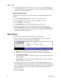
Ethernet
Ethernet
Configure the residential gateway’s Ethernet settings on this screen.
Path: Setup > Ethernet
Note: There are two views available, Basic and Advanced. The default view is Basic.
To display the Advanced View, click Advanced View. To return to the Basic View,
click Basic View.
5th Ethernet Port
Complete the following steps to configure the fifth Ethernet port on your residential
gateway.
Note: If you use the fifth Ethernet port as a WAN port, then the ADSL port is
automatically disabled, and all routing goes to other Ethernet ports.
1
2
Select the desired Ethernet Connection setting as follows:
To use the fifth Ethernet port as a WAN port, select Use as WAN Port.
Continue with step 2.
To use the fifth Ethernet port as a Local Area Network (LAN) port, select Use
as LAN Port. Skip to step 3.
Configure the Ethernet WAN Setup settings that appear:
a
3425-00669 Rev E
Set Connection Shaping—To disable QoS Shaping, select No Shaping. To
shape according to link speed, select Auto (link speed). To manually enter
the shape rate, select Manual, and then enter the number of kbps in the field
provided.
33
Chapter 3 Setup
b
Select the connection you want to use:
–
Automatic Configuration - DHCP (This option usually applies to cable
connections.)
–
Static IP—If you select this option, you need to configure the following:
–
–
34
Internet IP Address—Enter the Gateway’s IP address, as seen from
the Internet.
Subnet Mask—Enter the Gateway’s Subnet Mask, as seen from the
Internet (including your service provider).
Default Gateway—Enter the IP address of the service provider’s
server.
Static DNS 1 (Required) and DNS 2 (Optional)—Enter the DNS
(Domain Name System) server IP address(es) provided by your
service provider. At least one is required.
PPPoE—Configure the Basic Settings for this connection type:
Username and Password—Enter the Username and Password
provided by your service provider.
Connect on Demand: Max Idle Time—You can configure the
Gateway to cut the Internet connection after it has been inactive for a
specified period of time (Max Idle Time). If your Internet connection
has been terminated due to inactivity, Connect on Demand enables
the Gateway to automatically re-establish your connection as soon as
you attempt to access the Internet again. To use this option, select
Connect on Demand. In the Max Idle Time field, enter the number of
minutes you want to have elapsed before your Internet connection
terminates. The default Max Idle Time is 5 minutes.
Keep Alive—If you select this option, the Gateway will periodically
check your Internet connection. If you are disconnected, then the
Gateway will automatically re-establish your connection. To use this
option, select Keep Alive.
PPPoE—Configure the Advanced Settings for this connection type:
Service Name—Enter the Service Name (optional) provided by your
service provider.
NAT—To use Network Address Translation, keep the default
Enabled. Otherwise, select Disabled.
IGMP Forwarding—Select Enabled, if you want to allow multicast
traffic through the Router for your multimedia application devices.
Otherwise, keep the default, Disabled.
VLAN ID Mark—Enter the 802.1Q VLAN ID Mark to be used on for
traffic to and from the interface associated with this connection. The
default is -1, which indicates that the VLAN connection is untagged.
Range is 0 through 4095.
3425-00669 Rev E
Ethernet
3
802.1p Mark—Enter the 802.1p (Ethernet priority) Mark to be used on
traffic sent out on this connection. A value of -1 indicates no change
from the incoming packet. The default is -1.
Override Ethernet Priority—If this option is disabled and the 802.1p
Mark is specified, then the 802.1p Mark is applied only to packets of
priority 0. If this option is enabled and the 802.1p Mark is specified,
then the 802.1p Mark is applied to all packets on this connection. To
enable this option, select the check box. Otherwise, leave the check
box blank.
RIP Recv Packet Version—Select the Routing Information Protocol
(RIP) version you want to use: RIP off, RIPv1, or RIPv2.
Domain Name—Enter the Domain Name for this connection. The
DNS proxy will compare Domain Names to choose the connection
that will send out DNS queries.
Click Save Settings to apply your changes, or click Cancel Changes to cancel
your changes.
Ethernet WAN Access
The Ethernet WAN is connected using the port labeled 'Ethernet WAN/LAN' on the
back of the WAG310G. This port, when configured as the WAN port, will allow
either 1 IP or 1 PPP connection. The Ethernet WAN may be configured to use a
DCHP, Static IP, or PPPoE connection and is configured in the SETUP/Ethernet
page by selecting the option 'Use as WAN Port'. If 'Use as LAN Port' is selected, the
5th LAN port becomes another Ethernet port on the LAN switch (and shows up in
PVC/VLAN mapping page).
By default the Ethernet WAN is disabled. The Ethernet WAN adds a level of
flexibility to the WAG310G by offering another method of WAN access. It can be
used to support high-bandwidth fiber (FTTx) network deployments or can be used
when placing the WAG310G behind a DSL/Cable modem and using as an wireless
access point and router.
Ethernet WAN is mutually exclusive with the ADSL WAN. Only one can be
activated at a time.
3425-00669 Rev E
35
Chapter 3 Setup
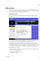
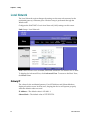
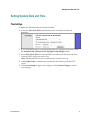
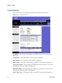
Local Network
The Local Network section changes the settings on the network connected to the
residential gateway’s Ethernet ports. Wireless setup is performed through the
Wireless tab.
Configure the WAG310G’s Local Area Network (LAN) settings on this screen.
Path: Setup > Local Network
Note: There are two views available, Basic and Advanced. The default view is Basic.
To display the Advanced View, click Advanced View. To return to the Basic View,
click Basic View.
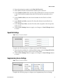
Gateway IP
The values for the residential gateway’s local IP Address and Subnet Mask are
displayed on this screen. In most cases, keeping the device will operate properly
when the default values are used.
IP Address—The default value is 192.168.1.1.
Subnet Mask—The default value is 255.255.255.0.
36
3425-00669 Rev E
Local Network
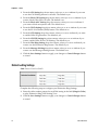
Network Address Server Settings (DHCP)
The Network Address Server Settings (DHCP) allow you to configure the residential
gateway’s Dynamic Host Configuration Protocol (DHCP) server function. The
residential gateway can be used as a DHCP server for your network. A DHCP server
automatically assigns an IP address to each computer on your network. If you
choose to enable the residential gateway’s DHCP server option, make sure there is
no other DHCP server on your network.
1
Select Enabled for the DHCP Server field to allow the server to automatically
assign an IP address to each computer on your network for you. Unless you
already have, Cisco recommends that you keep the default, Enabled.
2
Configure the following parameters per the guidelines provided:
3
3425-00669 Rev E
Starting IP Address—Enter a value for the DHCP server to start with when
issuing IP addresses. Because the gateway default IP address is 192.168.1.1,
the Starting IP Address must be 192.168.1.2 or greater, but smaller than
192.168.1.253. The default is 192.168.1.64.
Ending IP Address—Enter a value for the DHCP server to end with when
issuing IP addresses.. The default is 192.168.1.253.
Client Lease Time—The amount of time a network device is allowed
connection to the gateway with its current dynamic IP address. Enter the
number of minutes that the device is “leased” this dynamic IP address. After
the time is up, the device is automatically assigned a new dynamic IP
address. An entry of -1 means inifite lease. The default is 1440 minutes.
DNS Proxy (Advanced View)—The Domain Name System (DNS) is how the
Internet translates domain or website names into Internet addresses or URLs.
To use DNS Proxy, keep the default, Enable. Otherwise, select Disable.
Static DNS 1,2, 3 (Advanced View)—These entries are valid only when the
DNS Proxy option is disabled. At least one DNS server IP address is
provided by your ISP. You can enter up to three DNS server IP addresses
here. The gateway uses these for quicker access to functioning DNS servers.
WINS (Advanced View)—The Windows Internet Naming Service (WINS)
converts NetBIOS names to IP addresses. If you use a WINS server, enter that
server IP address here. Otherwise, leave this field blank.
Domain Name (Advanced View)—Enter the domain name of your local
network.
Reserved IP List (Advanced View)—Enter the IP addresses you want to
reserve, so they will not be leased to DHCP clients.
Click Save Settings to apply your changes, or click Cancel Changes to cancel
your changes.
37
Chapter 3 Setup
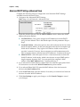
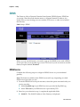
DHCP Options
DHCP Options settings are configurable and passed to WAG310G client requests. A
maximum of 15 DHCP Options can be entered for a local network or each
Conditional Serving entry.
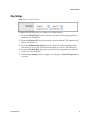
Complete the following steps to configure DHCP Options.
1
Click the DHCP Options button (available only if DHCP is enabled). A new
window appears.
2
Configure the following parameters per the guidelines provided:
3
DHCP Option—The following DHCP options are supported: 1, 3, 6, 12, 15,
43, 43, 51, 54, 56, 58, 59, 121, 125 and 128.
DHCP Option Value—This value is stored as binary string on the Gateway.
For some DHCP options, the user can enter a native format such as an IP
Address or integer; for others, the user must enter HEX strings to represent
binary string of a DHCP option. (No check is performed on these values.)
Click Save Settings to apply your changes, or click Go Back to cancel your
changes and return to the Local Network screen.
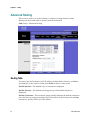
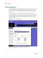
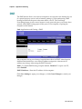
Conditional Serving
Conditional Serving Pool settings are configurable and passed to WAG310G client
requests.
Complete the following steps to configure the Conditional Serving Pool settings
(available only if DHCP is enabled).
1
Click the Conditional Serving button. A new window appears.
2
Configure the Conditional Serving Pool parameters:
3
38
a
Enable DHCP Conditional Serving—To enable this option, select the check
box. Otherwise, leave the check box blank.
b
For each entry, the table lists the following: MAC Address, Vendor Class ID,
User Class ID, Client ID, Host Name, Domain Name, IP Address, Precedence,
and Action.
c
To delete an entry, click Delete. To configure the DHCP options for an entry,
click DHCP Option.
Configure the Conditional Serving Entry parameters:
Precedence—Enter the Precedence value. A lower value indicates higher
priority.
MAC Address—Enter the MAC Address, if applicable as a filter condition.
User Class ID—Enter the User Class ID, if applicable as a filter condition.
Vendor Class ID—Enter the Vendor Class ID, if applicable as a filter
condition.
3425-00669 Rev E
Local Network
Client ID—Enter the Client ID, if applicable as a filter condition. This field
accepts ASCII or hexadecimal strings. To enter a hexadecimal string, add 0x
before the string.
Host Name—Enter the Host Name, if applicable as a filter condition.
IP Address—If there is a match, the DHCP server will assign this IP Address
to the host.
Domain Name—If there is a match, the DHCP server will assign this Domain
Name to the host.
4
Click Add Entry to add a new entry to the table. Click Save Settings to apply
your changes.
5
Click Back to LAN Setup to return to the Local Network screen.
6
Configure the following parameters:
7
Starting IP Address—Enter a value for the DHCP server to start with when
issuing IP addresses. Because the Gateway’s default IP address is 192.168.1.1,
the Starting IP Address must be 192.168.1.2 or greater, but smaller than
192.168.1.253. The default is 192.168.1.64.
Ending IP Address—Specify the final IP address of the range available for
assignment. The default is 192.168.1.253.
Client Lease Time—The Client Lease Time is the amount of time a network
device will be allowed connection to the Gateway with its current dynamic IP
address. Enter the number of minutes that the device will be “leased” this
dynamic IP address. After the time is up, the device will be automatically
assigned a new dynamic IP address. The default is 1440 minutes.
Click the Advanced View link and configure the available options:
DNS Proxy—The Domain Name System (DNS) is how the Internet translates
domain or website names into Internet addresses or URLs. To use DNS
Proxy, keep the default, Enable. Otherwise, select Disable.
Static DNS 1-3—These entries are valid only when the DNS Proxy option is
disabled. At least one DNS server IP address is provided by your service
provider. You can enter up to three DNS server IP addresses here. The
Gateway will use these for quicker access to functioning DNS servers.
WINS— The Windows Internet Naming Service (WINS) converts NetBIOS
names to IP addresses. If you use a WINS server, enter that server’s IP
address here. Otherwise, leave this field blank.
Domain Name—Enter the Domain Name of your local network.
Reserved IP List—Enter the IP addresses you want to reserve, so they will
not be leased to DHCP clients.
8
Click Add Entry; then, click Back to LAN Setup to return to the Local Network
screen.
9
Click Save Settings to save.
3425-00669 Rev E
39
Chapter 3 Setup
Advanced DHCP Settings (Advanced View)
Complete the following steps to configure the Local Network DHCP Settings
available from the Advanced View:
40
1
Navigate to the Advanced DHCP Settings.
Path: Setup > Local Network > Advanced View
2
Select the desired option for the the DHCP Address, which defines the DHCP
address allocation method:
Use DHCP Pool—This option assigns local IP addresses from the DHCP
pool you have defined. This is the default option for this parameter. Skip to
step 5.
Use WAN Subnet—Select this option to have the local network devices share
the WAN subnet address. In this pass-through mode, the local computers get
WAN-side IP addresses. They bypass NAT and are visible on the service
provider’s network. However, these computers can still communicate with
other computers that are allocated private IP addresses. Continue with step 3.
Share WAN IP—Select this option to have a local network device share the
WAN IP address. In this mode, which is also known as super-DMZ mode, a
single computer bypasses NAT. You can specify the computer’s MAC
address in the MAC Address field. Continue with step 3.
3
If you selected Use WAN Subnet or Share WAN IP, select the appropriate WAN
IP connection to use from the WAN IP Interface drop-down menu.
4
If you selected Share WAN IP, enter the MAC address of the local network
device in the MAC Address field.
5
In the Lease Time field, enter the number of seconds you want the local network
device to lease the WAN IP address.
6
Click Save Settings to apply your changes, or click Cancel Changes to cancel
your changes.
3425-00669 Rev E
Setting System Date and Time
Setting System Date and Time
Time Settings
Complete the following steps to set time and date.
1
In the the Time Zone field, select the time zone in which your network
functions.
2
If you want the Gateway to automatically adjust for daylight saving time, select
the Automatically adjust clock for daylight saving changes option.
3
In the NTP Server 1/2 field, enter the URL (web address) of the Network Time
Protocol (NTP) server you want to use.
Note: The default NTP servers are time.nist.gov and clock.isc.org.
4
Click Update Time to immediately synchronize the Gateway with the NTP
server.
5
Click Save Settings to apply your changes, or click Cancel Changes to cancel
your changes.
3425-00669 Rev E
41
Chapter 3 Setup
DDNS
The Gateway offers a Dynamic Domain Name System (DDNS) feature. DDNS lets
you assign a fixed host and domain name to a dynamic Internet IP address. It is
useful when you are hosting your own website, FTP server, or other server behind
the Gateway.
Path: Setup > DDNS
Before you can use this feature, you need to sign up for DDNS service with a DDNS
service provider, www.dyndns.org or www.TZO.com. If you do not want to use this
feature, keep the default, Disabled.
DDNS Service
Complete the following steps to configure a DDNS Service on your residential
gateway.
Note: The features available on the DDNS screen will vary, depending on which
DDNS service provider you use.
1
From the DDNS Service drop-down menu, select the option associated with your
service provider:
2
Select TZO.com if your DDNS service is provided by TZO.
Based on your selection in step 1, complete the applicable fields:
42
Select DynDNS.org if your DDNS service is provided by DynDNS.org.
WAN IP—The WAN IP address of the Gateway is displayed.
3425-00669 Rev E
DDNS
3
3425-00669 Rev E
User/Email—Enter the user name or e-mail address for your account.
Password/Key—Enter the password or key for your account.
Host Name—Enter the DDNS URL assigned by the service.
Status—The status of the DDNS service connection is displayed.
Connect—To manually trigger an update, click this button.
Click Save Settings to apply your changes, or click Cancel Changes to cancel
your changes.
43
Chapter 3 Setup
Advanced Routing
This screen is used to set up the Gateway’s advanced routing functions. Static
Routing sets up a fixed route to another network destination.
Path: Setup > Advanced Routing
Routing Table
For each route, the Destination LAN IP address, Subnet Mask, Gateway, and Metric
are displayed. In the Action column, click Delete to delete a static route.
Default Interface—The default Layer 3 connection is displayed.
Default Gateway—The default next-hop gateway of the default interface is
displayed.
Default Connection—This advanced setting usually indicates the default connection
since the Gateway supports multiple WAN connections. If the Gateway has multiple
connections, specify which one is the default.
44
3425-00669 Rev E
Advanced Routing
Static Routing
A static route is a pre-determined pathway that network information must travel to
reach a specific host or network. Enter the information described below to set up a
new static route.
Note: When you add a static route, certain rules apply. For example, the Gateway
must belong to the subnet of any of the router’s interfaces.
Destination IP Address—The Destination IP Address is the IP address of the remote
network or host to which you want to assign a static route.
Subnet Mask—The Subnet Mask determines which portion of a Destination IP
Address is the network portion, and which portion is the host portion.
Gateway—This is the IP address of the gateway device that allows for contact
between the Gateway and the remote network or host.
Metric—This is the number of hops to each node until the destination is reached (16
hops maximum). Enter the appropriate Metric. The default is 1.
To save the static route you have configured, click Add Entry. Click Save Settings to
apply your changes, or click Cancel Changes to cancel your changes.
3425-00669 Rev E
45
Chapter 3 Setup
PVC/VLAN Mapping
This advanced screen is used to map the PVCs to the Virtual Local Area Networks
(VLANs). When you create a mapping, a layer 2 bridge is formed between the
Gateway’s LAN port (including WLAN SSID) and WAN port (PVC or Ethernet
WAN).
Cisco recommends that you configure this screen according to your service
provider’s instructions. For example, when Ethernet port 1 is connected to a set-top
box, a PVC mapping is created for Ethernet port 1 and PVC 1 with VLAN 1002.
Traffic is marked with the configured VLAN ID when it travels to the service
provider’s network.
Path: Setup > PVC/VLAN Mapping
Select PVC Connection—Select the PVC you want to map.
46
3425-00669 Rev E
PVC/VLAN Mapping
VLAN Bridge Table
For each entry, the table lists the following: LAN Ports, VLAN ID, 802.1p, MAC
Address, Ethernet Frame, Enable status, and Action. To delete an existing
PVC/VLAN mapping, click Delete.
VLAN Bridge Entry
Enabled—Select Enabled to enable the mapping rule.
Enable IGMP Proxy—Select for more efficient use of resources for gaming or
applications.
VLAN ID—Enter the VLAN you want to map. The default is 2.
MAC Address—Enter the packet’s source MAC address, if applicable as a filter
condition.
802.1p—Enter the priority level for each port. These are the mappings to 802.1p:
6 High (highest, EF)
5 Medium (CS)
4 Normal (CS)
0 Low (best effort)
-1 No Change (no change to the original 8021. p value)
Cisco recommends the following:
For voice and video traffic, enter 6.
For gaming or mission-critical traffic, enter 5.
For normal traffic, enter 4.
For low-priority traffic, enter 0.
LAN Ports—Every LAN interface is listed, including the Ethernet ports and Wireless
Local Area Network (WLAN) ports. (The WLAN ports are listed with their wireless
network names, also known as SSIDs.) Select the appropriate LAN interface. For
multiple selection, press the Ctrl or Shift key. To deselect, use Ctrl + click (click the
selection).
Ethernet Frame—The Ethernet frame types are listed. Select the packet’s Ethernet
frame type, if applicable as a filter condition. For multiple selection, press the Ctrl or
Shift key. To deselect, use Ctrl + click (click the selection).
Click Add VLAN Bridge to create a new PVC/VLAN mapping, or click Cancel
Changes to cancel your changes
3425-00669 Rev E
47
Chapter 3 Setup
48
3425-00669 Rev E
4 Chapter 4
Wireless
Introduction
The WAG310G supports a single-radio, single antenna Access Point
with the ability to configure 4 separate SSIDs. An existing SSID
'wag310g' is enabled by default. Additional SSIDs, SSID Broadcasting,
and Security settings can be configured separately per SSID.
There are two ways to configure security for the WAG310G. The webconfiguration GUI enables an administrator to configure different
security modes for an SSID. The WAG310G supports WEP,
WPA-Personal, WPA-Enterprise, WPA2-Personal, WPA2-Enterprise,
and WPS. By default, security is disabled.
In This Chapter
3425-00669 Rev E
Basic Settings ......................................................................................... 50
Security ................................................................................................... 52
MAC Filter ............................................................................................. 57
Wi-Fi Protected Setup .......................................................................... 59
Advanced Settings ................................................................................ 62
49
Chapter 4 Wireless
Basic Settings
Path: Wireless > Basic Settings
The basic settings for wireless networking are set on this screen.
There are two ways to configure the residential gateway’s wireless settings, manual
and Wi-Fi Protected Setup. For manual configuration, use this screen to change the
settings.
Wi-Fi Protected Setup is a feature that makes it easy to set up your wireless network.
If you have devices that support Wi-Fi Protected Setup, then click the Wi-Fi
Protected Setup tab, and follow the on-screen instructions (refer to the Wi-Fi
Protected Setup (on page 59) section for more information).
Note: Wi-Fi Protected Setup can only be used for the default wireless network. (The
residential gateway supports up to four wireless networks. The other three can be
configured using the residential gateway’s web-based utility.)
50
3425-00669 Rev E
Wireless Network
Wireless Network
Wireless Channel—Select the channel you want to use. All devices in your wireless
network must use the same channel in order to communicate. If you do not select a
particular channel number, the default setting will be Auto-scan Channel in which
case the residential gateway scans the network and chose the channel with the least
interference.
Wireless Network State—Select the wireless standards running on your network. If
you have Wireless-G and Wireless-B devices in your network, keep the default,
Mixed. If you have only Wireless-G devices, select G-Only. If you have only
Wireless-B devices, select B-Only. If you do not have any wireless devices, select
Disabled.
The Gateway supports up to four wireless networks. By default, only the first
wireless network is enabled. On the Wireless Security and MAC Filter screens, you
can configure different security settings and MAC filtering rules for each wireless
network.
Configure the following settings for each wireless network (SSID1-4):
Wireless Network Name (SSID)—The network name is case-sensitive and must
not exceed 32 characters (use any of the characters on the keyboard). Cisco
recommends that you change the default name of the first network to a unique
name of your choice.
Wireless Network State—If you want to use the wireless network, select
Enabled. Otherwise, select Disabled.
Wireless SSID Broadcast—When wireless devices survey the local area for
wireless networks to associate with, they will detect the wireless network name
or SSID broadcast by the Gateway.
If you want to broadcast the residential gateway’s SSID, keep the default,
Enabled. Otherwise, select Disabled.
Click Save Settings to apply your changes, or click Cancel Changes to cancel your
changes.
3425-00669 Rev E
51
Chapter 4 Wireless
Security
The Wireless Security screen configures the security of your wireless network(s). The
gateway supports the following wireless security mode options:
Wi-Fi Protected Access (WPA)-Personal
WPA2-Personal
Wired Equivalent Privacy (WEP)
WPA-Enterprise
WPA2-Enterprise
WPA is a stronger security standard than WEP encryption.
Note: If you used Wi-Fi Protected Setup to configure your wireless network(s),
wireless security has already been set up. Do not make changes to the Security
screen.
Path: Wireless > Security
Wireless Network—Select the wireless network you want to configure.
Security Mode—Select the security method for your wireless network. Proceed to
the appropriate instructions. If you do not want to use wireless security, keep the
default, Off.
52
3425-00669 Rev E
Security
Note: If you are using wireless security, remember that each device in your wireless
network MUST use the same security method and settings, or else the wireless
devices cannot communicate.
Wireless Security Checklist
Wireless networks are convenient and easy to install, so homes with high-speed
Internet access are adopting them at a rapid pace. Because wireless networking
operates by sending information over radio waves, it can be more vulnerable to
intruders than a traditional wired network. Like signals from your cellular or
cordless phones, signals from your wireless network can also be intercepted. Since
you cannot physically prevent someone from connecting to your wireless network,
you need to take some additional steps to keep your network secure.
Change the Default Wireless network Name or SSID
Wireless devices have a default wireless network name or Service Set Identifier
(SSID) set by the factory. This is the name of your wireless network, and can be up to
32 characters in length. Cisco wireless products use wag310g as the default wireless
network name. You should change the wireless network name to something unique
to distinguish your wireless network from other wireless networks that may exist
around you, but do not use personal information (such as your Social Security
number) because this information may be available for anyone to see when browsing
for wireless networks.
Change the Default Password
For wireless products such as access points, routers, and gateways, you will be asked
for a password when you want to change their settings. These devices have a default
password set by the factory. The Cisco default password is admin. Hackers know
these defaults and may try to use them to access your wireless device and change
your network settings. To thwart any unauthorized changes, customize the device’s
password so it will be hard to guess.
Enable MAC Address Filtering
Cisco routers and gateways give you the ability to enable Media Access Control
(MAC) address filtering. The MAC address is a unique series of numbers and letters
assigned to every networking device. With MAC address filtering enabled, wireless
network access is provided solely for wireless devices with specific MAC addresses.
For example, you can specify the MAC address of each computer in your home so
that only those computers can access your wireless network.
Enable Encryption
Encryption protects data transmitted over a wireless network. Wi-Fi Protected
Access (WPA/WPA2) and Wired Equivalent Privacy (WEP) offer different levels of
security for wireless communication.
3425-00669 Rev E
53
Chapter 4 Wireless
A network encrypted with WPA/WPA2 is more secure than a network encrypted
with WEP, because WPA/WPA2 uses dynamic key encryption. To protect the
information as it passes over the airwaves, you should enable the highest level of
encryption supported by your network equipment.
WEP is an older encryption standard and may be the only option available on some
older devices that do not support WPA.
General Network Security Guidelines
Wireless network security is useless if the underlying network is not secure.
Password protect all computers on the network and individually password
protect sensitive files.
Change passwords on a regular basis.
Install anti-virus software and personal firewall software.
Disable file sharing (peer-to-peer). Some applications may open file sharing
without your consent and/or knowledge.
Additional Security Tips
Keep wireless routers, access points, or gateways away from exterior walls and
windows.
Turn wireless routers, access points, or gateways off when they are not being
used (at night, during vacations).
Use strong passphrases that are at least eight characters in length. Combine
letters and numbers to avoid using standard words that can be found in the
dictionary.
Allowable Character Sets:
–
54
Username and SSID may contains letters, numbers, and/or special
characters EXCEPT:
Spaces or tabs
&, `, (, ), <, or > character
Consecutive underscores __
An underscore_, dash -, or period . at the beginning
–
Password may contain any letters, numbers, and/or special characters
EXCEPT spaces or tabs
–
Other fields as string type could be any string
3425-00669 Rev E
Security
WPA2-Personal
Mixed Mode—Select Enabled to support both WPA and WPA2 clients. Otherwise,
keep the default, Disabled.
Encryption—Select the appropriate method, AES or TKIP or both.
Passphrase—Enter a Passphrase (also called a WPA shared key) of 8-63 characters.
Key Renewal—Enter a Key Renewal period, which instructs the residential gateway
how often it should change the encryption keys. The default is 3600 seconds.
WPA-Personal
Encryption TKIP is automatically selected.
Passphrase—Enter a Passphrase (also called a WPA shared key) of 8-63 characters.
Key Renewal—Enter a Key Renewal period, which instructs the Gateway how often
it should change the encryption keys. The default is 3600 seconds.
WEP
Encryption—Select a level of WEP encryption, 40/64-bit (10 hex digits) or 104/128bit (26 hex digits).
Passphrase—Enter a Passphrase to automatically generate WEP keys. Then click
Generate.
Note: The WEP Passphrase is compatible with Cisco wireless products only. If you
are using non-Cisco products, manually enter the appropriate WEP key on those
devices.
Key 1-4—If you did not enter a Passphrase, enter the WEP key(s) manually.
TX Key—Select which TX (Transmit) Key to use. The default is 1.
3425-00669 Rev E
55
Chapter 4 Wireless
WPA Enterprise
This option features WPA used in coordination with a RADIUS server. (RADIUS
stands for Remote Authentication Dial-In User Service. This option should only be
used when a RADIUS server is connected to the residential gateway.)
Encryption TKIP is automatically selected.
RADIUS Server—Enter the IP address of the RADIUS server.
RADIUS Port—Enter the port number of the RADIUS server. The default value is
1812.
Shared Key—Enter the key shared between the residential gateway and the server.
Key Renewal—Enter a Key Renewal period, which instructs the residential gateway
how often it should change the encryption keys. The default is 3600 seconds.
WPA2 Enterprise
This option features WPA2 used in coordination with a RADIUS server. (It should
only be used when a RADIUS server is connected to the Gateway.)
Mixed Mode—Select Enabled to support both WPA and WPA2 clients. Otherwise,
keep the default, Disabled.
Encryption—Select the appropriate method, AES or TKIP or both.
RADIUS Server—Enter the IP address of the RADIUS server.
RADIUS Port—Enter the port number of the RADIUS server. The default value is
1812.
Shared Key—Enter the key shared between the Gateway and the server.
Key Renewal—Enter a Key Renewal period, which instructs the Gateway how often
it should change the encryption keys. The default is 3600 seconds.
Click Save Settings to apply your changes, or click Cancel Changes to cancel your
changes.
56
3425-00669 Rev E
MAC Filter
MAC Filter
Wireless access can be filtered by using the MAC addresses of the wireless devices
transmitting within your network’s wireless network coverage.
Path: Wireless > MAC Filter
Wireless MAC Filter
Select Wireless Network (SSID)—Select the wireless network you want to
configure.
Enabled/Disabled—To use the wireless MAC filter, select Enabled. Otherwise, keep
the default, Disabled.
3425-00669 Rev E
57
Chapter 4 Wireless
MAC Address Filter
Filter As White List/Filter As Black List—To allow access by network devices with
the MAC addresses on this list, select Filter As White List. To block access by
network devices with the MAC addresses on this list, keep the default, Filter As
Black List.
MAC 01-20—Enter the MAC addresses of the devices whose wireless access you
want to block or allow.
For each wireless device, its MAC address and connection status are listed. To copy
a MAC address to one of the MAC 01-20 fields, click Copy.
Click Save Settings to apply your changes, or click Cancel Changes to cancel your
changes.
58
3425-00669 Rev E
Wi-Fi Protected Setup
Wi-Fi Protected Setup
There are two ways to configure the residential gateway’s wireless settings, manual
and Wi-Fi Protected Setup. For manual configuration, click the Basic Settings tab
(refer to the Basic Settings (on page 50) section for more information).
Wi-Fi Protected Setup is a feature that makes it easy to set up your wireless network.
If you have devices that support Wi-Fi Protected Setup, then use the following
instructions.
Note: Wi-Fi Protected Setup can only be used for the default wireless network. (The
residential gateway supports up to four wireless networks. The other three can be
configured using the Wireless > Basic Settings screen of the residential gateway’s
web-based utility.)
If you have client devices, such as a wireless adapter, that support Wi-Fi Protected
Setup, then you can use Wi-Fi Protected Setup to automatically configure wireless
security for your wireless network(s).
There are three methods available. Use the method that applies to the client device
you are configuring.
Note: Wi-Fi Protected Setup configures one client device at a time. Repeat the
instructions for each client device that supports Wi-Fi Protected Setup.
3425-00669 Rev E
59
Chapter 4 Wireless
Path: Wireless > Wi-Fi Protected Setup
Method #1
Use this method if your client device has a Wi-Fi Protected Setup button.
1
Click or press the Wi-Fi Protected Setup button on the client device. (If Wi-Fi
Protected Setup is an on-screen option, then select it.)
2
Click the Wi-Fi Protected Setup button on the residential gateway's Wi-fi
Protected Setup screen.
3
After the client device has been configured, click OK. Then refer back to your
client device or its documentation for further instructions.
Method #2
Use this method if your client device has a Wi-Fi Protected Setup PIN number.
60
1
Enter the client PIN number in the PIN field on this screen (the residential
gateway’s Wi-Fi Protected Setup screen).
2
Click Register on this screen.
3425-00669 Rev E
Wi-Fi Protected Setup
Method #3
Use this method if your client device asks for the Router’s PIN number.
1
Enter the PIN number that appears on your screen. (It is also listed on the Wi-Fi
Protected Setup label on the bottom of the Router.)
Note: This is a unique number. Do not use the number that appears in the
example above.
2
After the client device has been configured, click OK. Then refer back to your
client device or its documentation for further instructions.
At the bottom of the screen, status information for your wireless security is
displayed:
Wi-Fi Protected Setup Simple-Config-State—The status of the Wi-Fi Protected
Setup feature is displayed. The default is “Not configured.” After the Router has
been configured, the status changes to “Configured.”
Network Name (SSID)—The name of the wireless network is displayed.
Security—The security method of the wireless network is displayed.
Encryption—The encryption method, such as TKIP or AES, is displayed.
Passphrase—The passphrase for the wireless security method is displayed. It
acts like a password for access to the wireless network. (For WPA security
methods, the passphrase is also known as a WPA shared key.)
Note: If you have client devices that do not support Wi-Fi Protected Setup, note
the wireless settings, and then manually configure those client devices.
3425-00669 Rev E
61
Chapter 4 Wireless
Advanced Settings
Use this screen to set up the Gateway’s advanced wireless settings, which apply to
all of the Gateway’s wireless networks. These settings should only be adjusted by an
expert administrator as incorrect settings can reduce wireless performance.
Path: Wireless > Advanced Settings
Advanced Wireless
Basic Rate—The Basic Rate setting is not actually one rate of transmission but a
series of rates at which the Gateway can transmit. The Gateway will advertise its
Basic Rate to the other wireless devices in your network, so they know which rates
will be used. The Gateway will also advertise that it will automatically select the best
rate for transmission. Select the appropriate option:
Default, for transmission at all standard wireless rates
1-2Mbps, for use with older wireless technology
All, for transmission at all wireless rates
Wi-Fi Alt, the basic rates are 1, 2, 5.5, 6, 11, 12, and 24 Mbps; supported rates are
9, 18, 36, 48, and 54 Mbps. If you are not sure which rate to select, keep the
default, Default.
62
3425-00669 Rev E
Advanced Settings
CTS Protection Mode—CTS (Clear-To-Send) Protection Mode’s default is Disabled.
Select Auto if you want the device to automatically use CTS Protection Mode when
your Wireless-G products are experiencing severe problems and are not able to
transmit to the device in an environment with heavy 802.11b traffic. This function
boosts the device’s ability to catch all Wireless-G transmissions but will severely
decrease performance.
Control TX Rate—The Control TX Rate should be set depending on the speed of
your wireless network. Select from a range of transmission speeds, or keep the
default, Auto. When the Auto setting is selected, the Gateway automatically uses the
fastest possible data rate and enables the Auto-Fallback feature, which negotiates the
best possible connection speed between the Gateway and a wireless device.
Wireless Afterburner—To improve wireless performance when the Gateway is used
with devices that support SpeedBooster, select Enable. Otherwise, keep the default,
Disable.
Beacon Interval—Enter a value between 1 and 65,535 milliseconds. The Beacon
Interval value indicates the frequency interval of the beacon. A beacon is a packet
broadcast by the Gateway to synchronize the wireless network(s). The default value
is 100.
DTIM Interval—This value, between 1 and 255, indicates the interval of the
Delivery Traffic Indication Message (DTIM). A DTIM field is a countdown field
informing clients of the next window for listening to broadcast and multicast
messages. When the Gateway has buffered broadcast or multicast messages for
associated clients, it sends the next DTIM with a DTIM Interval value. Its clients hear
the beacons and awaken to receive the broadcast and multicast messages. The
default value is 1.
Fragmentation Threshold—This value specifies the maximum size for a packet
before data is fragmented into multiple packets. If you experience a high packet
error rate, you may slightly increase the Fragmentation Threshold. Setting the
Fragmentation Threshold too low may result in poor network performance. Only
minor reduction of the default value is recommended. In most cases, it should
remain at its default value of 2346.
RTS Threshold—Should you encounter inconsistent data flow, only minor
reduction of the default, 2346, is recommended. If a network packet is smaller than
the preset RTS threshold size, the RTS/CTS mechanism will not be enabled. The
Gateway sends Request to Send (RTS) frames to a particular receiving station and
negotiates the sending of a data frame. After receiving an RTS, the wireless station
responds with a Clear to Send (CTS) frame to acknowledge the right to begin
transmission. The RTS Threshold value should remain at its default value of 2346.
3425-00669 Rev E
63
Chapter 4 Wireless
WMM Support—The Gateway supports Wi-Fi Multimedia (WMM) for Quality of
Service (QoS). When WMM Support is enabled, it provides four priority queues for
different types of traffic. It automatically maps the incoming packets to the
appropriate queues based on QoS settings (in the IP or layer 2 header). WMM
provides the capability to prioritize traffic in your environment. If you have other
devices on your network that support WMM, select Enable. Otherwise, keep the
default, Disable.
Auto Power Save Delivery—Unscheduled Automatic Power Save Delivery
(UAPSD) is a special power-saving mode to achieve end-to-end QoS. This option is
available if you enabled WMM Support. To use the power save feature, select Auto
Power save Delivery.
Click Save Settings to apply your changes, or click Cancel Changes to cancel your
changes.
64
3425-00669 Rev E
5 Chapter 5
Voice
Introduction
The WAG310G provides phone ports so you can use your residential
gateway for your phone calls. This chapter contains a high-level
overview of just a few of the many voice features.
In This Chapter
3425-00669 Rev E
About Voice ........................................................................................... 66
Info .......................................................................................................... 67
System .................................................................................................... 72
User1 or User2 ....................................................................................... 74
65
Chapter 5 Voice
About Voice
There are two views available, User and Admin. The default view is User. To display
the Admin View, click Admin View. If you are prompted for the admin login, enter
your admin name and password. To return to the User View, click User View.
Admin View
If the Gateway was provided by your service provider, then it may restrict access to
the Admin View of the Voice screens in the web-based utility. Contact your service
provider for the admin login.
User View
VoIP configuration parameters are primarily managed by your service provider;
therefore, most of the screens in the User View mode do not provide input fields for
configuring VoIP options.
Use the table below as a quick reference for Voice configuration tabs that have
configurable parameters in the User View.
66
Screen
Description
Info
The Voice> Info screen does not have input fields. This screen
provides information regarding VoIP activity. Refer to the Info (on
page 67) section for descriptions of the data fields displayed.
System
The Voice > System tab has an input field for setting up a User
Password. Refer to the System (on page 72) section for instructions
on managing this parameter.
Provisioning
Managed by your service provider.
Regional
Managed by your service provider.
SIP
Managed by your service provider.
Line1 / Line2
Managed by your service provider.
PSTN
Managed by your service provider.
User1 / User2
The Voice > User1 and Voice > User2 tabs have input fields in the
User View mode for setting up features such as Call Forwarding.
Refer to the User1 or User2 (on page 74) section for instructions on
managing these parameters.
3425-00669 Rev E
Info
Info
The Info screen displays Voice over Internet Protocol (VoIP) information about the
Gateway. (The User and Admin Views are the same for this screen.)
Path: Voice > Info
3425-00669 Rev E
67
Chapter 5 Voice
VoIP
RTP Packets Sent—The number of RTP packets sent by the Gateway is displayed.
RTP Bytes Sent—The number of RTP bytes sent by the Gateway is displayed.
RTP Packets Recv—The number of RTP packets received by the Gateway is
displayed.
RTP Bytes Recv—The number of RTP bytes received by the Gateway is displayed.
SIP Messages Sent—The number of session initiation protocol (SIP) messages sent
by the Gateway is displayed.
SIP Bytes Sent—The number of SIP bytes sent by the Gateway is displayed.
SIP Messages Recv—The number of SIP messages received by the Gateway is
displayed.
SIP Bytes Recv—The number of SIP bytes received by the Gateway is displayed.
External IP—The external IP address used for NAT mapping is displayed.
68
3425-00669 Rev E
Info
Line 1/2 Status
Lines 1 and 2 have the same status information available.
Path: Voice > Info
Hook State—The status of the Internet phone line’s readiness is displayed. “On”
indicates that it is ready for use, while “Off” indicates that it is in use.
Registration State—The status of the line’s registration with the Internet Telephony
Service Provider (ITSP) is displayed.
Hazardous Potential—The amount of hazardous potential is displayed.
Last Registration—At The last date and time the line was registered are displayed.
Foreign Voltage—The amount of foreign voltage is displayed.
3425-00669 Rev E
69
Chapter 5 Voice
Next Registration—In The number of seconds until the next registration is
displayed.
Diff Resistive Fault—The amount of differential resistive fault is displayed.
Message Waiting— his indicates whether you have new voicemail waiting.
Long Resistive Fault—The amount of long resistive fault is displayed.
Call Back Active—This indicates whether a call back request is in progress.
REN—The Ringer Equivalence Number (REN) is displayed.
Last Called Number—The last number called is displayed.
Last Caller Number—The number of the last caller is displayed.
Mapped SIP Port—The port number of the NAT mapped SIP port is displayed.
Call 1/2 Status
Calls 1 and 2 have the same status information available.
Path: Voice > Info
Call 1/2 State—The status of the call is displayed.
Call 1/2 Tone—The type of tone used by the call is displayed.
Call 1/2 Encoder—The codec used for encoding is displayed.
Call 1/2 Decoder—The codec used for decoding is displayed.
Call 1/2 FAX—The status of the fax pass-through mode is displayed.
Call 1/2 Type—The direction of the call is displayed.
Call 1/2 Remote Hold—This indicates whether the far end has placed the call on
hold.
Call 1/2 Callback—This indicates whether the call was triggered by a call back
request.
Call 1/2 Peer Name—The name of the internal phone is displayed.
Call 1/2 Peer Phone—The phone number of the internal phone is displayed.
Call 1/2 Duration—The duration of the call is displayed.
Call 1/2 Packets Sent—The number of packets sent is displayed.
Call 1/2 Packets Recv—The number of packets received is displayed.
Call 1/2 Bytes Sent—The number of bytes sent is displayed.
Call 1/2 Bytes Recv—The number of bytes received is displayed.
70
3425-00669 Rev E
Info
Call 1/2 Decode Latency—The number of milliseconds for decoder latency is
displayed.
Call 1/2 Jitter—The number of milliseconds for receiver jitter is displayed.
Call 1/2 Round Trip Delay—The number of milliseconds for delay is displayed.
Call 1/2 Packets Lost—The number of packets lost is displayed.
Call 1/2 Packet Error—The number of invalid packets received is displayed.
Call 1/2 Mapped RTP Port—The number of the NAT mapped RTP port is displayed.
PSTN Line Status
Path: Voice > Info
PSTN Hook State—The status of the PSTN phone line’s readiness is displayed.
“On” indicates that it is ready for use, while “Off” indicates that it is in use.
PSTN Line Voltage—The tip-to-ring voltage of the Line (FXO) port is displayed.
PSTN Loop Current—The loop current to the Line (FXO) port is displayed.
3425-00669 Rev E
71
Chapter 5 Voice
System
The System screen displays system settings. (The User View only accesses the User
Password setting.)
Path: Voice > System
System Configuration
Path: Voice > System
The System screen displays system settings.
72
3425-00669 Rev E
System
Note: The User View only accesses the User Password setting.
Complete the following steps to setup a password for user access to the Voice
screens.
1
Enter the password in the User Password field. By default, there is no password.
2
Click the Save Settings button to apply your changes or Cancel Changes button
to cancel.
3425-00669 Rev E
73
Chapter 5 Voice
User1 or User2
The User1 and 2 screens display similar settings. The User1 screen displays settings
for users of phone line 1, and the User2 screen displays settings for users of phone
line 2. (The User and Admin Views are the same for this screen.)
74
3425-00669 Rev E
User1 or User2
Path: Voice > User1 or User2
3425-00669 Rev E
75
Chapter 5 Voice
Call Forward Settings
Path: Voice > User1 or User2
Complete the following steps to configure your Call Forward Settings.
1
Enter the call forwarding numbers you want to use per the guidelines below:
Cfwd All Dest—Enter the number for the Call Forward All Service feature
(when you want to forward all calls).
Cfwd Busy Dest—Enter the number for the Call Forward Busy feature
(when the line is busy).
Cfwd No Ans Dest—Enter the number for the Call Forward No Answer
feature (when the line is not answered).
2
In the Cfwd No Ans Delay, enter the number of seconds to wait before the Call
Forward No Answer feature is triggered. The default is 20.
3
Click the Save Settings button to apply your changes or Cancel Changes button
to cancel.
Selective Call Forward Settings
Path: Voice > User1 or User2
Complete the following steps to configure your Selective Call Forward Settings.
1
76
Enter the caller number pattern to trigger the Call Forward Selective (1-8)
feature in the Cfwd Sel1 Caller field.
3425-00669 Rev E
User1 or User2
2
Enter the destination number in the Cfwd Sel1 Dest field.
3
Enter additional caller and destination number pairs as desired.
4
In the Cfwd Last Caller field, enter the caller number that is actively forwarded
to the Cfwd Last Dest number when the Call Forward Last activation code is
used.
5
In the Cfwd Last Dest, enter the forward number for the Cfwd Last Caller
feature.
6
In the Block Last Caller, enter the ID of the caller blocked via the Block Last
Caller service.
7
In the Accept Last Caller, enter the ID of the caller accepted via the Accept Last
Caller service.
8
Click the Save Settings button to apply your changes or Cancel Changes button
to cancel.
Speed Dial Settings
Path: Voice > User1 or User2
Complete the following steps to configure your Speed Dial Settings.
1
Enter the phone number for each Speed Dial setting in the field (Speed Dial 2-9)
that corresponds to the key want to use for that number.
2
Click the Save Settings button to apply your changes or Cancel Changes button
to cancel.
Supplementary Service Settings
Path: Voice > User1 or User2
Complete the following steps to configure your Supplementary Service Settings.
3425-00669 Rev E
77
Chapter 5 Voice
1
From the CW Setting drop-down menu, select yes or no to indicate if you want
to use the Call Waiting feature for all calls. The default is yes.
2
From the Block CID Setting drop-down menu, select yes or no to indicate if you
want to block Caller ID for all calls. The default is no.
3
From the Block ANC Setting drop-down menu, select yes or no to indicate if
you want to block anonymous calls. The default is no.
4
From the DND Setting drop-down menu, select yes or no to indicate if you want
to use the Do Not Disturb (DND) feature. The default is no.
5
From the CID Setting drop-down menu, select yes or no to indicate if you want
to enable Caller ID generation. The default is yes.
6
From the CWCID Setting drop-down menu, select yes or no to indicate if you
want to enable Caller ID for Call Waiting. The default is yes.
7
From the Dist Ring Setting drop-down menu, select yes or no to indicate if you
want to use the Distinctive Ring feature. The default is yes.
8
From the Message Waiting drop-down menu, select yes or no to indicate if you
want to use the Message Waiting feature. The default is no.
9
Click the Save Settings button to apply your changes or Cancel Changes button
to cancel.
Distinctive Ring Settings
Path: Voice > User1 or User2
Complete the following steps to configure your Distinctive Ring Settings.
78
1
Enter the caller number pattern for each Dial setting in the field (Ring1-8 Caller)
to play Distinctive Ring/Call Waiting Tone.
2
Click the Save Settings button to apply your changes or Cancel Changes button
to cancel.
3425-00669 Rev E
User1 or User2
Ring Settings
Path: Voice > User1 or User2
Complete the following steps to configure your Ring Settings.
1
From the Default Ring drop-down menu, select the default ringing pattern for
all callers. The default is 1.
2
From the Default CWT drop-down menu, select the default CWT pattern for all
callers. The default is 1.
3
From the Hold Reminder Ring drop-down menu, select the ring pattern that
will remind you of a call on hold when the phone is on-hook. The default is 8.
4
From the Call Back Ring drop-down menu, select the ring pattern for call back
notification. The default is 7.
5
Click the Save Settings button to apply your changes or Cancel Changes button
to cancel.
3425-00669 Rev E
79
6 Chapter 6
Storage
Introduction
The WAG310G supports network attachable storage devices (USB
Memory Key, Hard Drives, including multiple partitions) through the
USB 2.0 interface and HTTP. The WAG310G is able to manage storage
content through the WAN interface using HTTP.
In This Chapter
3425-00669 Rev E
Storage .................................................................................................... 82
81
Chapter 6 Storage
Storage
LAN clients can access storage using the following URL:
http://<gateway ip address>/Disk_Browse.bsp.
To access storage from the WAN, use the URL
http://<DDNSName:port>/Disk_Browse.bsp. You will need to disable the Firewall
or enable Remote Management to launch the URL.
Note: DDNS is recommended to track WAN IP automatically.
82
3425-00669 Rev E
Storage
Disk Detail
The Disk Detail screen lists the location, Make and Model, Physical Size, and Free
Space of the storage device connected to the residential gateway’s USB port.
For USB storage, the residential gateway supports the following features:
USB 2.0
Auto-mounting of external USB hard drive
FAT/FAT32 file system
Display of disk information
File browsing
File search
Creation of new directories
File deletion, copying, moving, or renaming
File downloads (save files to the computer from USB storage)
File uploads (save files from the computer to USB storage)
Path: Storage > Disk Detail
Click Refresh to update the on-screen information.
3425-00669 Rev E
83
Chapter 6 Storage
Disk Management
The Disk Management screen allows you to search and manage the storage device
connected to the residential gateway’s USB port.
Path: Storage > Disk Management
Select Disk—Select the storage location.
Current Location—The location of the current directory is displayed.
Current Directory—The number of files is displayed.
Search—Enter the term you want to look for in the current directory, and then click
Search.
New Directory—To create a new directory, click New Directory, and follow the onscreen instructions.
Upload File—To upload a file to the current directory, select it from the list, and
then click Upload File. To upload all files in the current directory, select Select All.
The files are displayed with the following information: Type, Name, Size, and
Modified Date.
Click Refresh to update the on-screen information.
To delete a file or directory, select it and then click Delete. To copy a file or directory
to a new location, select it and then click Copy. To move a file or directory to a new
location, select it and then click Move. To rename a file or directory, select it and
then click Rename.
Note: If you have DDNS service, you can manage the storage device using the WAN
IP address. To allow WAN HTTP access, you must enable remote access on the
Administration > Management screen and disable the firewall on the Security >
Firewall screen.
84
3425-00669 Rev E
7 Chapter 7
Security Configuration
Introduction
This chapter describes setting up Firewall security to filter out various
types of unwanted traffic on the residential gateway’s local network.
In This Chapter
3425-00669 Rev E
Firewall ................................................................................................... 86
85
Chapter 7 Security Configuration
Firewall
The Firewall screen is used to configure a firewall that can filter out various types of
unwanted traffic on the residential gateway’s local network.
Path: Security > Firewall
Intrusion Detection Protection—To use Intrusion Detection System (IDS) and
Denial of Service (DoS) protection, select Enabled. Otherwise, keep the default,
Disabled.
Web Content Filtering—To filter web content, keep the default, Enabled. Otherwise,
select Disabled. (This feature must be enabled to use the Website Blocking options
on the Access Restrictions > Internet Access Policy screen.)
Max Firewall Sessions—Enter the maximum number of firewall sessions that will
be processed at any given time.
Max QoS Sessions—Enter the maximum number of QoS sessions that will be
processed at any given time.
SIP ALG—The SIP ALG feature assists VoIP phones behind the residential gateway
when NAT problems are encountered. This feature also assists QoS (when enabled)
with automatic classification of SIP- and RTP-related traffic. To use the SIP ALG
feature, keep the default, Enabled. Otherwise, select Disabled.
86
3425-00669 Rev E
Firewall
Firewall Profile
Apply Firewall Profile—For a low level of firewall protection, keep the default,
Low. For a high level of firewall protection, select High. To disable the firewall,
select Off.
To configure user-based security rules, click Access Restrictions. (Refer to the
Internet Access Policy (see on page 91) section for details.)
Click Save Settings to apply your changes, or click Cancel Changes to cancel your
changes.
3425-00669 Rev E
87
8 Chapter 8
Access Restrictions
Introduction
This chapter describes setting up an Intranet Access Policy to manage
the access restrictions for your residential gateway.
In This Chapter
3425-00669 Rev E
Internet Access Policy .......................................................................... 90
89
Chapter 8 Access Restrictions
Internet Access Policy
This Access Restrictions screen is used to set up and manage Internet access policies.
An Internet Access Policy allows you to block or allow specific kinds of Internet
usage and traffic, such as Internet access, designated services, and websites during
specific days and times.
Path: Access Restrictions > Internet Access Policy
90
3425-00669 Rev E
Internet Access Policy
Create or Modify an Internet Access Policy
Complete the following steps to create a new policy or modify an existing policy.
1
In the Access Policy Rule section of the screen, select a policy from the Internet
Access Policy drop-down menu.
a
If you are setting up a new policy, select Add New Rule. If you select an
existing policy, the screen refreshes with that policy's settings.
Note: Multiple rules can be created for the same computer. Rules have
priorities, so the first matched rule determines the computer’s access policy.
b
From the Status field, select the Enabled radio button to enable the policy, or
Disabled to disable the policy.
c
In the PC (IP or Host) Name field, enter the host name or IP address of the
computer for which this policy applies.
2
In the Access restriction section, click the appropriate option, Deny or Allow,
depending on whether you want to block or allow Internet access for the PCs
you listed on the List of PCs screen.
3
If you wish to block access to websites, use the Website Blocking by Keyword
or Website Blocking by Regular Expression feature.
3425-00669 Rev E
To use Website Blocking by Keyword, enter the URL or Domain Name of the
websites you wish to block.
Note: If any of these Keywords appears in the URL of a website, access to the
site will be blocked. Note that only the URL is checked, not the content of
each web page.
91
Chapter 8 Access Restrictions
4
92
To use Website Blocking by Regular Expression, enter the expression you
wish to block in the fields provided.
Note: A regular expression is a string used to describe or match a set of
strings. You can block websites that use strings encompassed by the regular
expressions you enter on this screen. Enter each regular expression in a
separate field.
Regular Expression Syntax:
.
any character
^
start of a line
$
end of a line
*
match zero or many times
?
match zero or one time
+
match one or more times
{m,n}
match from m to n times (m <= n)
{n}
match exactly n times
[a-c]
character set
[^a-c]
negative charset
|
or
(“ and “)
brackets for grouping
\xx
escaped character
Use any combination of the following options to block services in the Blocked
Services section to filter access to various applications accessed over the Internet,
such as FTP or telnet.
Block a preset applications—The block services select list offers a choice of
preset applications. For multiple selection, press the Ctrl or Shift key.
Note: If you select a preset application, its port numbers and protocol are
displayed and can not be changed.
Block a new service—If the application you want to block is not listed, select
the Service link; then, you can enter the port range and protocol for the
service you wish to block. The new service is added to the list.
3425-00669 Rev E
Internet Access Policy
Remove blocking—To remove the blocking, press Ctrl + click to deselect a
service.
5
In the Schedule section, select the individual days during which the policy will
be in effect, or select Everyday. Then, enter a range of hours and minutes during
which the policy will be in effect, or select 24 Hours.
6
Set the policy as follows:
3425-00669 Rev E
If you are creating a new rule, click the Add Rule button to add policy rule
settings.
If your are modifying an existing rule, click the Save Settings button to save
policy rule settings.
If you wish to cancel your inputs, click Cancel Changes.
93
9 Chapter 9
Applications & Gaming
Introduction
This chapter describes setting up the gateway to support applications
and games.
In This Chapter
3425-00669 Rev E
Single Port Forwarding ........................................................................ 96
Port Range Forwarding ........................................................................ 98
DMZ ...................................................................................................... 100
Port Range Triggering ........................................................................ 101
QoS (Quality of Service) ..................................................................... 103
Service................................................................................................... 106
95
Chapter 9 Applications & Gaming
Single Port Forwarding
The Single Port Forwarding screen allows you to set up public services on your
network, such as web servers, ftp servers, e-mail servers, or other specialized
Internet applications. (Specialized Internet applications are any applications that use
Internet access to perform functions such as video conferencing or online gaming.
Some Internet applications may not require any forwarding.)
When users send these types of requests to your network via the Internet, the
Gateway will forward those requests to the appropriate servers (computers). Before
using forwarding, you should assign static IP addresses to the designated servers.
Path: Applications & Gaming > Single Port Forwarding
To forward a port, enter the information on each line for the criteria required.
96
3425-00669 Rev E
Single Port Forwarding
Application—Select the appropriate application: HTTP (80), HTTPS (443), FTP (21),
Windows Media Player (1755), DNS (53), POP3 (110), Simple Mail Transfer (25), or
TR069 Connection Request (888).
Internal Port—Enter the internal port number used by the server or Internet
application. Check with the Internet application documentation for more
information.
IP Address—For each application, enter the IP address of the computer that should
receive the requests.
Enabled—For each application, select Enabled to enable port forwarding.
Click Save Settings to apply your changes, or click Cancel Changes to cancel your
changes.
3425-00669 Rev E
97
Chapter 9 Applications & Gaming
Port Range Forwarding
The Port Range Forwarding screen allows you to set up public services on your
network, such as web servers, ftp servers, e-mail servers, or other specialized
Internet applications. (Specialized Internet applications are any applications that use
Internet access to perform functions such as videoconferencing or online gaming.
Some Internet applications may not require any forwarding.)
When users send these types of requests to your network via the Internet, the
Gateway will forward those requests to the appropriate servers (computers). Before
using forwarding, you should assign static IP addresses to the designated servers.
Note: If you need to forward all ports to one computer, click the DMZ tab.
Path: Applications & Gaming > Port Range Forwarding
To forward a port range, enter the information on each line for the criteria required.
Application—Select the appropriate application.
98
3425-00669 Rev E
Port Range Forwarding
Note: If you do not see the application you want, configure the service on the
Applications & Gaming > Service screen.
IP Address—For each application, enter the IP address of the computer running the
specific application.
Enabled—Select Enabled to enable port forwarding for the applications you have
defined.
Click Save Settings to apply your changes, or click Cancel Changes to cancel your
changes.
3425-00669 Rev E
99
Chapter 9 Applications & Gaming
DMZ
The DMZ feature allows one network computer to be exposed to the Internet for use
of a special-purpose service such as Internet gaming or videoconferencing. DMZ
hosting forwards all the ports at the same time to one PC. The Port Range
Forwarding feature is more secure because it only opens the ports you want to have
opened, while DMZ hosting opens all the ports of one computer, exposing the
computer to the Internet.
Path: Applications and Gaming > DMZ
Any computer whose port is being forwarded must have its DHCP client function
disabled and should have a new static IP address assigned to it because its IP
address may change when using the DHCP function.
DMZ—To disable DMZ hosting, keep the default, Disabled. To expose one PC,
select Enabled.
DMZ IP Address—Enter the IP address of the computer.
Click Save Settings to apply your changes, or click Cancel Changes to cancel your
changes.
100
3425-00669 Rev E
Port Range Triggering
Port Range Triggering
The Port Range Triggering screen allows the Gateway to watch outgoing data for
specific port numbers. The IP address of the computer that sends the matching data
is remembered by the residential gateway, so that when the requested data returns
through the residential gateway, the data is pulled back to the proper computer by
way of IP address and port mapping rules.
Path: Applications & Gaming > Port Range Triggering
To trigger a port range, enter the information on each line for the criteria required.
Application Name—Enter the unique application name of the trigger.
Triggered Range—For each application, enter the starting and ending port numbers
of the triggering port number range. These are the ports used by initiating traffic.
Check with the Internet application documentation for the port number(s) needed.
Protocol—For each application, select the appropriate protocol, TCP(6) or UDP(17).
Forwarded Range—For each application, enter the starting and ending port
numbers of the forwarded port number range. These are the ports used by incoming
traffic. Check with the Internet application documentation for the port number(s)
needed.
Allow Multiple Hosts—Select this option to allow multiple hosts in returned traffic.
3425-00669 Rev E
101
Chapter 9 Applications & Gaming
Enabled—Select Enabled to enable port triggering for the applications you have
defined.
Max Time Interval—Select
Click Save Settings to apply your changes, or click Cancel Changes to cancel your
changes.
102
3425-00669 Rev E
QoS (Quality of Service)
QoS (Quality of Service)
Quality of Service (QoS) ensures better service to high-priority types of network
traffic, which may involve demanding, real-time applications, such as
videoconferencing.
Note: The residential gateway’s QoS is for upstream traffic regulation only.
Downstream QoS is usually enforced by the service provider’s headend equipment.
Path: Applications & Gaming > QoS
Application-based QoS manages information as it is transmitted and received.
QoS—To use QoS, select Enabled. Otherwise, keep the default, Disabled.
Default Queue Index—Select the default queue (and priority) for applications not
specified below: 1-8. (A lower value has higher priority.)
Queue Management—A new window appears. Continue with the next section for
details.
3425-00669 Rev E
103
Chapter 9 Applications & Gaming
Queue Management
Path: Applications & Gaming > QoS > Queue Management button
The Queue table specifies the number and types of queues, queue parameters,
shaping behavior, and scheduling algorithm to use.
Each queue can be configured to be a “Strict Priority”, “WRR (Weighted Round
Robin)”, or “WFQ (Weighted Fair Queuing)” queue. One of the queues is
configured to be the default queue, which matches all traffic that cannot be classified
by the existing classification rules. The default settings are as follows:
Queue 1, 2, and 3 are Strict Priority queues (queue 1 has the highest priority)
Queue 4, 5, and 6 are WFQ queues and share the same priority (lower than 1, 2,
and 3)
Queue 7 and 8 are also WFQ queues but with the lowest priority
Queue 8 is set to be the default queue
Note: We recommend that you use the default settings or those set by your service
provider.
104
3425-00669 Rev E
QoS (Quality of Service)
Queue Index—There are eight queues for each interface. You can configure the
parameters but cannot add or delete queues. Higher index queues generally
represent higher-priority queues. Queues 1-3 are Strict Priority (WP) queues, and
Queues 4-8 are priority-based Weighted Fair Queues (WFQ).
Precedence—Enter the Precedence value of this queue relative to the others. A lower
value indicates higher precedence.
Scheduler—Select the scheduling algorithm: SP, WFQ, or WRR (Weighted Round
Robin). The default is SP.
Dropper— Select the dropping algorithm used if there is congestion: RED (Random
Early Detection), DT (Drop Tail), or WRED (Weighted RED). The default is WRED.
Weight—When WFQ or WRR is used, this option is available and used only for
queues of equal precedence. Queues 4-6 have equal precedence, and Queues 7-8
have equal precedence. Queues 1-3 have higher precedence than Queues 4-6, while
Queues 4-6 have higher precedence than Queues 7-8.
Shaping—If the Shaping rate is greater than or equal to 100, then it is the percentage
of physical bandwidth. If the Shaping rate is less than 100, then it is the rate in bits
per second. A value of -1 indicates no shaping. The default is -1.
Burst Size—Enter the Burst Size in bytes (1 to 10485760). For both leaky bucket
(constant rate shaping) and token bucket (variable rate shaping) algorithms, the
Burst Size value is the bucket size and the maximum burst size. If you set this value
to zero, then the Gateway will use the system default Burst Size, which is the current
Shaping rate divided by eight. The default is 0.
Click Save Settings to apply your changes, or click Back to QoS to cancel your
changes and return to the QoS screen.
3425-00669 Rev E
105
Chapter 9 Applications & Gaming
Service
The Service screen allows you to add services.
Path: Applications & Gaming > Service
Service Table
The services are displayed with the following information: Service Name, Protocol,
Ports/ Types, and Action. To delete a user-defined service, click Delete. (Default
services cannot be deleted.)
To view additional services, click Extended View. To return to the Basic View, click
Basic View.
Service Entry
Service Name—Enter a name for the new service.
106
3425-00669 Rev E
Service
Protocol—Select the appropriate protocol: TCP(6), UDP(17), ICMP, ESP(50), AH(51),
GRE(47), IGMP(2), PIM-DM(103), or IPCOMP(108).
Ports—Enter the starting and ending port numbers.
ICMP Type—Enter the appropriate number, 0-255, which is valid only for ICMP.
IGMP Type—Enter the appropriate number, 0-255, which is valid only for IGMP.
Click Add Service to add a new service, or click Cancel Changes to cancel your
changes.
3425-00669 Rev E
107
10 Chapter
Administration
Introduction
This chapter describes the configuration parameters managed by your
network administrator.
In This Chapter
3425-00669 Rev E
Management ........................................................................................ 110
Log ........................................................................................................ 113
IP Ping .................................................................................................. 115
ATM F5 Loopback .............................................................................. 116
Backup .................................................................................................. 117
Factory Defaults .................................................................................. 118
Firmware Upgrade ............................................................................. 119
Reboot ................................................................................................... 120
Logging out of the Residential Gateway ......................................... 121
109
Chapter 10 Administration
Management
The Management screen allows the network’s administrator to manage specific
residential gateway functions for access and security.
Path: Administration > Management
110
3425-00669 Rev E
Management
Local Gateway Access
To ensure the residential gateway’s security, you will be asked for your username
and password when you access the residential gateway’s web-based utility. The
default username and password are admin.
Gateway Username—Enter the default Gateway Username, admin.
Gateway Password—Cisco recommends that you change the default Gateway
Password, admin, to one of your choice.
Re-enter to Confirm—Enter the Gateway Password again to confirm.
Remote Gateway Access
Remote Management—To permit remote access of the Gateway, from outside the
local network, select Enabled. Otherwise, keep the default, Disabled.
Management Port—Enter the port number that will be open to outside access.
Management Protocol—Select the appropriate protocol, HTTP or HTTPS.
Note: When you are in a remote location and wish to manage the Gateway, enter
https://<Internet_IP_address>:port or http://<Internet_IP_address>:port. Enter the
Gateway’s specific Internet IP address in place of <Internet_IP_address>, and enter
the Management Port number in place of the word port.
Remote User Name—Enter the login user name for remote management.
Remote User Password—Enter the login password for remote management.
IGMP
IGMP Proxy—IGMP (Internet Group Membership Protocol) Forwarding (Proxying)
is a system to improve multicasting for LAN-side clients. This should be set to
Enabled if your clients support it, otherwise, select Disabled.
IGMP Querier Version—Select: Version 1, Version 2 or Version 3.
Query Interval—Only valid when IGMP Forwarding is enabled, default is 125
seconds.
Querier Immediate Leave—Only valid when IGMP Forwarding is enabled, default
is enabled.
Note: IGMPv2 is turned on by default and v3 is supported. IGMP Snooping is
turned on by default for all bridges.
3425-00669 Rev E
111
Chapter 10 Administration
UPnP
Universal Plug and Play (UPnP) allows Windows XP and Vista to automatically
configure the Gateway for various Internet applications, such as gaming and video
conferencing.
UPnP—If you want to use UPnP, keep the default setting, Enabled. Otherwise, select
Disabled.
Voice
Voice—To use this option, select Enabled. Otherwise, keep the default, Disabled.
Click the Save Settings button to apply your changes or Cancel Changes button to
cancel.
112
3425-00669 Rev E
Log
Log
The residential gateway can keep logs of traffic and events for your Internet
connection.
Path: Administration > Log
Reporting
Log—To disable the Log function, select Disabled. To monitor traffic between the
network and the Internet, keep the default, Enabled. With logging enabled, you can
choose to view temporary logs.
Log Severity—Select the severity level of the log events you want to view:
Informational, Warning (default), or Critical.
System Log Server—To enable system log server support, enter the IP address of the
system log server. To disable system log server support, leave this setting blank.
3425-00669 Rev E
113
Chapter 10 Administration
Email Alert
Email Alerts (For Warning Events)—To enable E-Mail Alerts for Warning-level
events, select Enabled. Otherwise, keep the default, Disabled.
SMTP Mail Server—Enter the address (domain name) or IP address of the Simple
Mail Transport Protocol (SMTP) server for outgoing e-mail.
User Name—Enter the User Name for SMTP authentication.
Password—Enter the Password for SMTP authentication.
Email to Address—Enter the e-mail address that will receive alert logs.
Email From Address—Enter the return address for the e-mail alerts. (This can be a
dummy address.)
Event Log
For each log, the Event Log displays the following information: Time, Description,
Source Address, and Destination Address.
Click Save Settings to apply your changes. Click Clear Event Log to clear all of the
events. Click Refresh to update the on-screen information.
114
3425-00669 Rev E
IP Ping
IP Ping
The ping test allows you to check the connections of your network devices,
including connection to the Internet.
Path: Administration > IP Ping
Target IP/FQDN—Enter the IP address or Fully Qualified Domain Name (FQDN)
that you want to ping. This can be either a local (LAN) or Internet (WAN) IP
address.
Ping Size—Enter the packet size you want to use. The default is 32 bytes.
Number of Pings—Enter how many times you want to ping. The default is 3.
Ping Timeout—Enter the number of milliseconds before the ping test will time out.
The default is 5000 milliseconds.
Ping Result—The results of the ping test are displayed.
To run the test, click Start Test. Click Refresh to update the on-screen information.
3425-00669 Rev E
115
Chapter 10 Administration
ATM F5 Loopback
Path: Administration > ATM F5 Loopback
PVC Connection—Select the PVC connection you want to configure.
Number of Pings—Enter how many times you want to ping. The default is 3.
Ping Timeout—Enter the number of milliseconds before the ping test will time out.
The default is 5000 milliseconds.
Ping Result—The results of the ping test are displayed.
To run the test, click Start Test. Click Refresh to update the on-screen information.
116
3425-00669 Rev E
Backup
Backup
The Backup screen allows you to back up or restore the residential gateway’s
settings using a configuration file.
Path: Administration > Backup
Backup Configuration
Backup—To save the Gateway’s settings in a configuration file, click this button and
follow the on-screen instructions.
Note: The voice settings will not be saved in the configuration file.
Restore Configuration
To use this option, you must have previously backed up its configuration settings.
Please select a file to restore—Click Browse and select the residential gateway’s
configuration file.
Restore—To restore the residential gateway’s configuration settings, click this
button and follow the on-screen instructions.
3425-00669 Rev E
117
Chapter 10 Administration
Factory Defaults
The Factory Defaults screen allows you to restore the residential gateway’s
configuration to its factory default settings. (An alternative method is to press and
hold the Reset button on the residential gateway’s back panel for approximately ten
seconds.)
Path: Administration > Factory Defaults
Note: Restoring factory defaults deletes custom settings. Note your custom settings
before clicking the Restore Factory Defaults button.
Restore Factory Defaults—To reset settings to the default values, click this button
and follow the on-screen instructions. Any custom Gateway settings you have saved
will be lost when the default settings are restored.
118
3425-00669 Rev E
Firmware Upgrade
Firmware Upgrade
The Upgrade screen allows you to upgrade the residential gateway’s firmware. Do
not upgrade the firmware unless you are experiencing problems with the residential
gateway or the new firmware has a feature you want to use.
Note: The residential gateway may lose the settings you have customized. Before
you upgrade its firmware, write down all of your custom settings. After you
upgrade its firmware, you will have to re-enter all of your configuration settings.
Path: Administration > Upgrade
Please Select a File to Upgrade—Click Browse and select the extracted firmware
upgrade file.
Start to Upgrade—After you have selected the appropriate file, click this button, and
follow the on-screen instructions.
Note: In rare cases (such as a power failure), the firmware upgrade may fail. If that
happens, the residential gateway will enter recovery mode and automatically
download firmware from your service provider’s provisioning server.
3425-00669 Rev E
119
Chapter 10 Administration
Reboot
The Reboot screen allows you to gracefully stop and restart the residential gateway.
Performing a reboot allows you to save any configuration changes and to reboot the
router to make the changes take effect.
Path: Administration > Reboot
Click Reboot Box to reboot the residential gateway. The restart will terminate the
Internet connection.
120
3425-00669 Rev E
Logging out of the Residential Gateway
Logging out of the Residential Gateway
The Logout screen allows you to properly exit the web-based utility.
Path: Administration > Logout
Click Logout to exit the web-based utility.
3425-00669 Rev E
121
11 Chapter
Status
Introduction
The Status screens provide a system summary of the software used by
the residential gateway and indicates the current status of the DSL
connection. You can use these screens to find hardware and software
information as well as physical and IP layer information.
In This Chapter
3425-00669 Rev E
Internet ................................................................................................. 124
Local Network ..................................................................................... 126
Wireless ................................................................................................ 128
DSL Connection .................................................................................. 129
Bridges .................................................................................................. 131
ARP Table ............................................................................................ 132
123
Chapter 11 Status
Internet
The Internet screen displays information about the Gateway and its current settings.
Path: Status > Internet
Gateway Information
Manufacturer OUI—The manufacturer ID number is displayed.
Serial Number—The serial number of the Gateway is displayed.
Hardware Version—The version number of the Gateway’s hardware is displayed.
Software Version—The version number of the Gateway’s software is displayed.
Region—The acronym for the time zone where the Gateway is geographically
located.
System Uptime—The length of time the Gateway has been active is displayed.
Local Time—The date and time of the Gateway are displayed.
124
3425-00669 Rev E
Internet
Internet Connection
This section shows the current information for enabled connections. The table lists
the following information about each connection: Interface, MAC/IP/Subnet,
Gateway, DNS, and Status.
For DHCP connections, you can manually renew or release them. For PPP-type
connections, you can manually connect or disconnect them.
Click Refresh to update the on-screen information.
3425-00669 Rev E
125
Chapter 11 Status
Local Network
The Local Network screen displays information about the local network.
Path: Status > Local Network
IP Address—The Gateway’s IP address, as it appears on your local network, is
displayed.
Subnet Mask—The Subnet Mask of the Gateway is displayed.
MAC Address—The Gateway’s MAC address is displayed.
DHCP Server—The status of the Gateway’s DHCP server function is displayed.
Starting IP Address—For the range of IP addresses used by devices on your local
network, the starting IP address is displayed.
Ending IP Address—For the range of IP addresses used by devices on your local
network, the ending IP address is displayed.
DHCP Lease Time—The length of time for the DHCP lease setting is displayed.
126
3425-00669 Rev E
Local Network
DHCP Client Table
The table displays DHCP, static, and dynamic (found by ARP) types of clients. It
describes the devices that have been assigned IP addresses by the Gateway. For each
device, the table lists the following information: Interface, MAC Address, IP
Address, Host Name, and Lease Remaining (how much time is left for the current IP
address).
IGMP Group Table
The table describes the IGMP configuration of the Gateway (if configured).
Click Refresh to update the on-screen information.
3425-00669 Rev E
127
Chapter 11 Status
Wireless
The Wireless screen displays information about your wireless network(s).
Path: Status > Wireless
For each wireless network, the following is displayed:
SSID—The name of the wireless network is displayed.
MAC Address—The MAC address of the Gateway’s local, wireless interface is
displayed.
Security—The wireless security method is displayed (if used).
SSID Broadcast—The SSID broadcast setting is displayed.
Max Bitrate—The maximum bitrate is displayed. This parameter is managed by
your service provider.
Click Refresh to update the on-screen information.
128
3425-00669 Rev E
DSL Connection
DSL Connection
The DSL Connection screen displays information about your DSL connection.
Path: Status > DSL Connection
Modulation Type—The DSL modulation mode of the Gateway is displayed.
Status—The status of the DSL connection is displayed.
Provider—The name of the service provider is displayed.
Downstream Rate—The download speed of traffic from the Internet to the Gateway
is displayed.
Upstream Rate—The upload speed of traffic from the Gateway to the Internet is
displayed. For ADSL connection, the Upstream Rate is typically 25% of the
Downstream Rate.
Note: The Downstream and Upstream Rates are affected by distance from and
configuration of the DSL central office.
Downstream Noise Margin—For downstream noise, the number of decibels (dB) is
displayed.
Upstream Noise Margin—For upstream noise, the number of decibels (dB) is
displayed.
3425-00669 Rev E
129
Chapter 11 Status
Downstream Attenuation—For downstream traffic, the amount of signal loss is
displayed.
Upstream Attenuation—For upstream traffic, the mount of signal loss is displayed.
Downstream Power—For downstream power, the number of decibels (referencing a
millivolt) is displayed.
Upstream Power—For upstream power, the number of decibels (referencing a
millivolt) is displayed.
Total Bytes Sent—The number of bytes sent is displayed.
Total Bytes Received—The number of bytes received is displayed.
PVC Connection
For each PVC connection, the table lists the following information: Index, Status,
Link Type, PVC, Encapsulation, QoS, PCR Rate, and SCR Rate.
Click Refresh to update the on-screen information.
130
3425-00669 Rev E
Bridges
Bridges
The Bridges screen displays information about the PVC/VLAN and default LAN
bridges of the Gateway Bridges.
Path: Status > Bridges
The total number of bridges and their descriptions are displayed.
Port (Name/Type)—The port name or type is displayed.
Learned Host (MAC/IP/Time to Expire)—The MAC address, IP address, or Time to
Expire duration is displayed.
IGMP Group (Group Address/Time to Expire)—The IGMP Group Information of
this port is displayed.
Click Refresh to update the on-screen information.
3425-00669 Rev E
131
Chapter 11 Status
ARP Table
This screen displays the Address Resolution Protocol (ARP) information.
Path: Status > ARP Table
Click Refresh to update the on-screen information.
132
3425-00669 Rev E
12 Chapter
Troubleshooting
Introduction
This chapter provides solutions to problems that may occur during the
installation and operation of the WAG310G.
In This Chapter
3425-00669 Rev E
Computer Cannot Connect to the Internet...................................... 134
Web Browser Prompts for Login Information ................................ 135
Computer Cannot Connect Wirelessly to the Network ................ 136
Modify the Advanced Settings ......................................................... 137
133
Chapter 12 Troubleshooting
Computer Cannot Connect to the Internet
If your computer cannot connect to the Internet, try the following solutions until the
connection is fixed:
Make sure that the residential gateway is powered on. The Power LED should be
green and not flashing.
If the Power LED is flashing, then power off all of your network devices,
including the residential gateway and computers. Then power on each device in
the following order:
a
Residential Gateway
b
Computer
Check the LEDs on the front panel of the residential gateway. Make sure the
Power, DSL, and at least one of the numbered LEDs are lit. If they are not, then
check the cable connections. The computer should be connected to one of the
ports numbered 1-4 on the residential gateway, and the Line port of the
residential gateway must be connected to the ADSL line.
134
3425-00669 Rev E
Web Browser Prompts for Login Information
Web Browser Prompts for Login Information
When you double-click the web browser, you are prompted for a user name and
password. If you want to get rid of the prompt, follow these instructions.
Launch the web browser and perform the following steps (these steps are specific to
Internet Explorer but are similar for other browsers):
1
Select Tools > Internet Options.
2
Click the Connections tab.
3
Select Never dial a connection.
4
Click OK.
3425-00669 Rev E
135
Chapter 12 Troubleshooting
Computer Cannot Connect Wirelessly to the
Network
Try this solution if your computer cannot connect wirelessly to the network.
Make sure the wireless network name or SSID is the same on both the computer and
the residential gateway. If you have enabled wireless security, then make sure the
same security method and key are used by both the computer and the residential
gateway.
136
3425-00669 Rev E
Modify the Advanced Settings
Modify the Advanced Settings
Perform the following steps if you need to modify the advanced settings on the
residential gateway.
1
Open the web browser (for example, Internet Explorer or Firefox), and enter the
residential gateway’s IP address in the address field (the default IP address is
192.168.1.1).
2
When prompted, complete the User name and Password fields (the default user
name and password is admin).
3
Click the appropriate tab to change the settings.
3425-00669 Rev E
137
13 Chapter
Specifications
Introduction
This chapter lists the interface and environmental specifications for the
WAG310G.
Note: Specifications are subject to change without notice.
In This Chapter
3425-00669 Rev E
Interfaces .............................................................................................. 140
Environmental ..................................................................................... 141
139
Chapter 13 Specifications
Interfaces
WAN
ADSL [ITU 992.1]; ADSL2 [ITU 992.3];
ADSL2+ [ITU 992.5] ANSI T1.413 Issue 2
1 RJ-11 Port
1 Ethernet WAN Interface RJ-45 Port (WAN/LAN configured)
LAN
Maximum of 5 Ports (RJ-45); Ethernet 10/100BASE-T with
Auto-Crossover (4 fixed + 1 configurable)
USB
1 USB 2.0 (host) Port
Phone
2 FXS Ports (RJ-11); 1 FXO Port (RJ-11)
Wi-Fi
IEEE 802.11b/g
802.1x Authentication
External RADIUS Authentication
WPA2 and WPA Access
WEP, AES & TKIP Encryption
WPA/WEP Mixed Mode
Wi-Fi Multimedia Support (WMM)
Multiple SSIDs
MAC Address Filtering Integrated
WPS (Push button & PIN entry)
Regional Channel Setting
LEDs
Power, Ethernet, Wireless, USB, Phone(s), Line, DSL, Internet
Buttons
On/Off, Reset, WPS
Mounting
Desktop and Wall Mount
Antenna
One Omni Directional External Antenna
140
3425-00669 Rev E
Environmental
Environmental
Dimensions
220 mm x 42 mm x 175 mm (8.66 in. x 1.65 in. x 6.89 in.)
Weight
400 g (14.11 oz)
Power
110-240 VAC 50/60 Hz Switching Power Supply; 12 VDC, 2 A Output
Certification
FCC Part 68, Part 15, Class B, UL1950, CSA, European EMC & Immunity, CE Mark,
Industry-Canada
Operating
Temp.
0° to 40°C (32° to 104°F)
Storage Temp.
0° to 70°C (32° to 158°F)
Humidity
20 to 80% Noncondensing
3425-00669 Rev E
141
14 Chapter
Customer Information
If You Have Questions
If you have technical questions, call Cisco Services for assistance.
Follow the menu options to speak with a service engineer.
Access your company's extranet site to view or order additional
technical publications. For accessing instructions, contact the
representative who handles your account. Check your extranet site
often as the information is updated frequently.
3425-00669 Rev E
143
Cisco Systems, Inc.
5030 Sugarloaf Parkway, Box 465447
Lawrenceville, GA 30042
678 277-1120
800 722-2009
www.cisco.com
This document includes various trademarks of Cisco Systems, Inc. Please see the Notices
section of this document for a list of the Cisco Systems, Inc. trademarks used in this
document.
Product and service availability are subject to change without notice.
©2009-2010, 2012 Cisco and/or its affiliates. All rights
reserved.
Part Number
July 2012 Printed in USA
3425-00669 Rev E