1
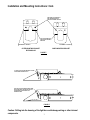
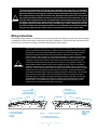
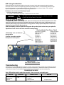
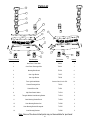
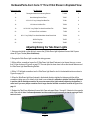
INSTALLATION
& OPERATION
MANUAL
SuperVisor U™
With Torus™ Technology
Interior Lighting System
Patents Pending
CONTENTS: Introduction............................................................................2
Unpacking & Pre-Installation.................................................2
Installation & Mounting.......................................................3-7
Wiring Instructions & Wiring Diagram ..................................8
Fusing LED Flash Pattern Selection & Troubleshooting........9
Exploded View, Parts & Hardware List........................... 10-11
Aiming the Take Down Lights......................................... 11-12
Notes..............................................................................13-15
Warranty..............................................................................1 6
For future reference, record your product's serial no. here __________________________________________
Read all instructions and warnings before installing and using.
IMPORTANT: INSTALLER:
This manual must be delivered to the end user of this equipment.
Introduction
The SuperVisor U™ (hereafter calld "unit") is an interior lighting system that fits in the visor area near the top of the windshield. The
Universal SuperVisor has room for up to ten Torus Light Heads.
Product Features
Torus light head options: Flashing = Red, Blue, Amber, and White--------Independent Flashing
Take Down Lights = White
Size: 50.75" MAX to 43.56"MIN length X 2.12" tall X 6.87" deep--------------------------------------------------Weight: 7.5 lbs
warning!
The use of this or any warning device does not ensure that all drivers can or will observe or react to an
emergency warning signal. Never take the right-of-way for granted. It is your responsibility to be sure you can
proceed safely before entering an intersection, driving against traffic, responding at a high rate of speed, or
walking on or around traffic lanes. The effectiveness of this warning device is highly dependent upon correct
mounting and wiring. Read and follow the manufacturer’s instructions before installing or using this device. The
vehicle operator should insure daily that all features of the device operate correctly. In use, the vehicle operator
should insure the projection of the warning signal is not blocked by vehicle components (i.e.: open trunks or
compartment doors), people, vehicles, or other obstructions. This equipment is intended for use by authorized
personnel only. It is the user’s responsibility to understand and obey all laws regarding emergency warning
devices. The user should check all applicable city, state and federal laws and regulations. Code 3, Inc., assumes
no liability for any loss resulting from the use of this warning device. Proper installation is vital to the performance
of this warning device and the safe operation of the emergency vehicle. It is important to recognize that the
operator of the emergency vehicle is under psychological and physiological stress caused by the emergency
situation. The warning device should be installed in such a manner as to: A) Not reduce the output performance
of the system, B) Place the controls within convenient reach of the operator so that he can operate the system
without losing eye contact with the roadway. Emergency warning devices often require high electrical voltages
and/or currents. Properly protect and use caution around live electrical connections. Grounding or shorting of
electrical connections can cause high current arcing, which can cause personal injury and/or severe vehicle
damage, including fire. Any electronic device may create or be affected by electromagnetic interference. After
installation of any electronic device operate all equipment simultaneously to insure that operation is free of
interference. Never power emergency warning equipment from the same circuit or share the same grounding
circuit with radio communication equipment. All devices should be mounted in accordance with the manufacturer's
instructions and securely fastened to vehicle elements of sufficient strength to withstand the forces applied to the
device. Driver and/or passenger air bags (SRS) will affect the way equipment should be mounted. This device
should be mounted by permanent installation and within the zones specified by the vehicle manufacturer, if any.
Any device mounted in the deployment area of an air bag will damage or reduce the effectiveness of the air
bag and may damage or dislodge the device. Installer must be sure that this device, its mounting hardware and
electrical supply wiring does not interfere with the air bag or the SRS wiring or sensors. Mounting the unit inside
the vehicle by a method other than permanent installation is not recommended as unit may become dislodged
during swerving, sudden braking or collision. Failure to follow instructions can result in personal injury. PROPER
INSTALLATION COMBINED WITH OPERATOR TRAINING IN THE PROPER USE OF EMERGENCY WARNING
DEVICES IS ESSENTIAL TO INSURE THE SAFETY OF EMERGENCY PERSONNEL AND THE PUBLIC.
Unpacking & Pre-installation
Carefully remove the Unit and place it on a flat surface, taking care not to scratch the lenses or damage the cable coming out of the
Housing. Examine the unit for transit damage, broken optics, LED's, etc. Report any damage to the carrier and keep the shipping carton.
Standard light bars are built to operate on 12 volt D.C. negative ground (earth) vehicles. If you have an electrical system other than 12
volt D.C. negative ground (earth), and have not ordered a specially wired light bar, contact the factory for instructions.
Test the unit before installation. To test, touch the black wire to the ground (earth) and the other wires to +12 volts D.C., in accordance
with the instructions attached to the cable (an automotive battery is preferable for this test). A battery charger may be used, but note that
some electronic options may not operate normally when powered by a battery charger. If problems occur at this point, contact the factory
Note: Before beginning the installation process, be absolutely certain
that the Light Bar functions as desired (See pages 8 & 9 for options)!
warning!
Utilizing non-factory supplied screws and/or mounting brackets and/or the improper
number of screws may result in loss of warranty coverage on the equipment.
Mounting Hardware - All mounting hardware is packed in a small bag inside the main carton. See pages 10 & 11 for part descriptions and quantities.
2
Installation and Mounting Instructions
Note to the installer: The following steps for the installation of the Unit may seem redundant or unnecessary, but in
order for the product to fit and perform properly these steps are necessary. The Unit's Inner and Outer Mounting Brackets
may require some trimming to properly fit the irregular recessed shapes of the the vehicle's headliner fabric, the shapes
of the plastic sun visor pivot brackets, and the shapes of the sun visor clip brackets. Many times the plastic brackets are
recessed up into the fabric of the headliner. These recesses will require that the outer edges of the Unit's Outer Mounting Brackets be trimmed to fit into the recess. The fit of the Unit's Inner and Outer Mounting Brackets to the headliner can
greatly affect the angles the brackets will be at when installed due to the inconsistant crush of the vehicle's headliner fabric
and the irregular shapes of the vehicle's sheet metal above the headliner fabric.The Unit's Inner and Outer Mounting Brackets may require bending to align with the Unit's Slotted Mounting Brackets and Outer Panels in the final assembly. The most
important issue in the installation is that the Unit must be securely fastened to the vehicle for passeneger safety and the unit
must be level in the vehicle to insure that the light bar will perform as intended (See Figure 3 on page 6). The installation
process may require trial and error to make adjustments to the Unit's Brackets to fit properly in their final location.
Step 1 Remove the vehicle's plastic outer visor pivot brackets to determine which of the (4) Unit's Outer Mounting Bracket
sets best fit the vehicle (See Figure-1 on page 5 for the (3) options). The Standard Round Outer Mounting Bracket with the
Triangular Washer will be the most commonly used set as the Triangular Washer allows the Round Outer Mounting Bracket
to rotate to accomodate extreme angles of rotation for adjustment while allowing the triangular hole in the washer to align
with the most common visor pivot bracket. If none of the Universal SuperVisor's Outer Mounting Bracket versions appear
to work for your application the Universal SuperVisor's Rectangular Outer Mounting Brackets may be cut off as shown in
Figure 5 on page 7. The brackets may then be used as a template to drill (2) 9/64" .140" diameter mounting holes directly
through the fabric of the headliner and through the vehicle's sheet metal above the headliner so that the brackets can be
mounted directly to the vehicle's headliner using the supplied #8 X 1" Black Phillips Truss Head Sheet Metal Screws. Caution: Before doing any drilling in the vehicle, refer to the vehicle's service manual to pull the fabric headliner down
slightly and observe the locations of any wiring or sensing devices to avoid doing damage to them!!! Also be very
careful not to drill through the vehicle's roof. If none of the bracket options are appropriate to the vehicle you are installing the Unit in, it may be necessary to make your own mounting brackets.
Step 2 Remove the vehicle's plastic inner visor clips. In a majority of vehicles the plastic inner visor clips will fit in the rect-
angular hole in the Unit's Inner Mounting Brackets but the Inner Mounting Brackets may require some modification with a
file or other cutting tool to clear the shapes in the vehicle's plastic visor clips. For vehicles with smaller inner visor clips you
may need to use the Unit's supplied Rectangular Washer in your vehicle application. Make any necessary modifications to
the Inner Mounting Brackets to make the vehicle's plastic visor brackets fit in the hole. If the Inner Mounting Brackets do not
work, the Inner Mounting Brackets may also be cut off as shown in Figure 5 on page 7 and the brackets can be mounted
by using the brackets as a template to drill (2) 9/64" .140" diameter mounting holes directly in the vehicle's headliner and
the sheet metal above the headliner fabric so that the brackets can be mounted directly to the vehicle's headliner using
the supplied #8 X 1" Black Phillips Truss Head Sheet Metal Screws. Caution Again: Before doing any drilling in the
vehicle, pull the headliner down slightly and observe the locations of any wiring or sensing devices to avoid doing
damage to them!!! Again as with the Outer Mounting Brackets, be very careful not to drill through the vehicle's
roof. If none of the bracket options are appropriate to the vehicle you are installing the Unit in, it may be necessary to make
your own mounting brackets for your application.
Step 3 Loosely fasten each of the Unit's Outer and Inner Mounting Brackets to a Slotted Mounting Bracket with (2) of
each of the provided 1/4"-20 X 1/2" long Carriage Bolts, 1/4" Internal Tooth Lock Washers, and the 1/4"-20 Acorn Nuts as
shown in Figure-2 on page 5. The Carriage bolts can be located in the slots in the brackets in what ever combination of
locations works best for your application to position the brackets at the required angles. Note: Figure-2 only shows the
assembly of the Unit's Inner Mounting Brackets but the assembly of the Outer Mounting Brackets is the same. As
stated above and as shown in Figure-2, it is recommended that each Outer or Inner Mounting Bracket is attached
to a Slotted Mounting Bracket with (2) of each of the 1/4"-20 X 1/2" long Carriage Bolts, 1/4" Internal Tooth Lock
Washers, and the 1/4"-20 Acorn Nuts. While the design allows for a good deal of adjustment in some circumstances where the brackets need to be attached at an extreme angle to each other, it may be necessary to file out the
mounting slots slightly in the brackets to accomodate the second fastener.
3
Installation and Mounting Instructions: Cont.
Step 4 Have an assistant hold either the Passenger or the Driver side of the the Unit up to the vehicle's windshield as
close as possible to desired location. Make sure that the rubber gasket on the Unit's lower Panel folds down to conform
to the vehicle's windshield curve and that the gasket at the top of the Unit folds back towards the passenger compartment
to conform to the angle of the vehicle's windshield (See Figure 3 on page 6). Note: In operation, the purpose of these
gaskets is to block out as much flash back light from the driver's view as possible so that the driver will not be
distracted. While the Unit is held in position, hold up the Inner and Outer Mounting Bracket assemblies to the Outer
Panel of the Unit to determine the appropriate mounting hole locations that best line up with the slots in the Slotted Mounting Brackets for each of the bracket assemblies.
Step 5 Loosley thread the 1/4" Internal Tooth Lock Washers, and the 1/4"-20 X 3/8" long Phillips Pan Head Screws into
the the closest appropriate mounting hole locations for the hardware and make adjustments to position them close to their
final position. See the under side view of the Unit Assembly in Figure 4 on page 6 for bracket assembly orientation and
mounting hole adjustment choices. As stated in note 2 above and as shown in Figure-4 it is recommended that each of
the Unit's Slotted Mounting Bracket use (2) each of the 1/4" Internal Tooth Lock Washers, and 1/4"-20 X 3/8" long Phillips
Pan Head Screws to mount it to the Unit's Outer Panel. Line up the holes in the Unit's Inner and Outer Mounting Brackets
with the holes in the vehicle's headliner where the vehicle's visor pivot brackets and the visor clips were installed. Once
the brackets are aligned, tighten the screws in the Unit's Outer Panel only tight enough too keep the Slotted Brackets in
their orientation and keep them from moving so that they will stay in position.
Step 6 Observe the angles and positions of the Inner and Outer Mounting Brackets and then disassemble and remove
them from the slotted mounting brackets.
Step 7 Hold the Unit's Outer Mounting Bracket for the side of the vehicle you have been working on up in position with
the hole in the vehicle's headliner where the plastic outer visor pivot bracket was and determine what modifications if necessary will be required to make it fit up against the headliner at the approximate angle it was in when you observed it in
step 6 above. Make any required modifications to make the bracket fit up against the headliner and fit the vehicle's plastic
outer pivot bracket.
Step 8 Mount the Unit's Outer Mounting Bracket and the vehicle's plastic visor pivot bracket using the vehicle's OEM
fasteners making sure the bracket is oriented at approximately the same angle it was at when you observed it in step 6
above. If the vehicle's OEM fasteners are too short either use the #8 X 1" Black Phillips Truss Head Sheet Metal Screws
or if the supplied fasteners will not work obtain appropriate screws at your local hardware store. Tighten the screws up to
snug the Outer Mounting Bracket tight up against the vehicle's headliner and in position.
Step 9 Mount the Unit's Inner Mounting Bracket and the vehicle's inner visor clip using the vehicle's OEM fastener
making sure the bracket is oriented at approximately the same angle it was at when you observed it in step 6 above. If the
vehicle's OEM fastener is too short either use the #8 X 1" Black Phillips Truss Head Sheet Metal Screw or if the supplied
fasteners will not work obtain appropriate screws at your local hardware store. Tighten the screw up to snug the Inner
Mounting Bracket tight up against the vehicle's headliner and in position.
Step 10 Hold the Unit Back up to the Installed Unit's Outer and Inner Mounting Brackets and determine if the angles of
the brackets need to be bent to re align them with the angled mounting tabs of the Slotted Mounting Brackets to facilitate
the final installation of the Unit. If necessary remove the Outer and Inner Mounting Brackets and bend the angles to line
them up with the Slotted Mounting Brackets or remove and bend the angles of the Slotted Mounting Brackets so that they
line up. Reposition all of the the Brackets, remount them to the vehicle's headliner and re fasten the Slotted Mounting
Brackets to the Inner and Outer Mounting Brackets. Note: The Unit's Gaskets must be up against the vehicle's windshield to block out as much light as possible and the Unit must be as close to level to the ground as possible in
the front to back direction when it is in it's final location. The Unit may be slightly out of level in the left to right
direction but should still be somewhat close to level in order to obtain maximum performance from the product when installed (See Figure 3 on page 6). It is very important that the vehicle is setting on a level floor when
checking the Unit for level before making adjustments for the final assembly. Make any required final adjustments
and fully tighten all hardware.
4
Installation and Mounting Instructions: Cont.
Step 11 Repeat steps 4 through 10 for the opposite side of the Unit.
Step 12 Once both sides of the Unit are installed, leveled and in the final position, loosen the screws on each
of the Inner and Outer Light Blocker Brackets, swing them up against the windshield and retighten the screws
to block out any flash back light that might come out the sides of the Unit (see Figure 6 on page 7).
Step 13 Route the Unit's cable as desired and complete the wiring process.
After the Unit is installed and wired, the Take Down Light Heads can be aimed if so equipped, See Page 11.
STANDARD ROUND OUTER
MOUNTING BRACKET
INNER MOUNTING BRACKET
RECTANGULAR OUTER
MOUNTING BRACKET
OVAL OUTER
MOUNTING BRACKET
STANDARD ROUND OUTER
MOUNTING BRACKET
W TRIANGULAR WASHER
SLOTTED MOUNTING BRACKET
Figure 1
Figure 2
5
SUV (TAHOE) OUTER
MOUNTING BRACKET
STANDARD INNER
MOUNTING BRACKET
W RECTANGULAR WASHER
Installation and Mounting Instructions: Cont.
THIS GASKET FLANGE TO FOLD
BACK THIS DIRECTION TOWARD
PASSENGER COMPARTMENT
WINDSHIELD
INTERIOR
SURFACE
THIS GASKET FLANGE TO FOLD
DOWN THIS DIRECTION WITH
CONTOUR OF WINDSHIELD
IN IT'S FINAL POSITION, THE SUPERVISOR MUST BE
AS LEVEL AS POSSIBLE IN FRONT TO BACK AXIS
IN IT'S FINAL POSITION, THE SUPERVISOR SHOULD BE
AS LEVEL AS POSSIBLE IN LEFT TO RIGHT AXIS BUT IS
NOT AS CRITICAL AS FRONT TO BACK AXIS
Figure 3
MOUNTING HOLE
LOCATION CHOICES
MOUNTING HOLE
LOCATION CHOICES
INNER MOUNTING
BRACKET ASSEMBLYS
OUTER MOUNTING
BRACKET ASSEMBLYS
UNDER SIDE VIEW OF UNIVERSAL SUPERVISOR
Figure 4
6
Installation and Mounting Instructions: Cont.
USE HOLES AS A TEMPLATE TO
DRILL MOUNTING HOLES IN
VEHICLE AT DESIRED LOCATION
CUT OFF AS SHOWN FOR
DRILLED AND FASTENED
BRACKETS
RECOMMEND 1/8" RADIUS 2X
RECOMMEND 1/8" RADIUS 2X
OUTER MOUNTING BRACKET
RECTANGULAR
INNER MOUNTING BRACKET
Figure 5
TO ADJUST LIGHT BLOCKER BRACKETS LOOSEN
THE FASTENING SCREW SLIGHTLY
TO ADJUST LIGHT BLOCKER BRACKETS, SWING
UP AS SHOWN UNTIL THE BRACKET TOUCHES
THE WINDSHIELD AND RETIGHTEN THE
FASTENING SCREW
Figure 6
Caution: Drilling into the housing of the light bar could damage wiring or other internal
components.
7
This unit must be mounted within the interior passenger compartment of the vehicle only. It is not intended for
use in exterior applications. All devices should be mounted in accordance with the manufacturer’s instructions
and securely fastened to vehicle elements of sufficient strength to withstand the forces applied to the device.
Driver and/or passenger air bags (SRS) will affect the way equipment should be mounted. This device should
be mounted by permanent installation and within the zones specified by the vehicle manufacturer, if any. Any
device mounted in the deployment area of an air bag will damage or reduce the effectiveness of the air bag and
WARNING:
may damage or dislodge the device. Installer must be sure that this device, its mounting hardware and electrical supply wiring does not interfere with the air bag or the SRS wiring or sensors. Mounting the unit inside
the vehicle by a method other than permanent installation is not recommended as unit may become dislodged
during swerving, sudden braking or collision. Failure to follow instructions can result in personal injury.
Wiring Instructions
Finish routing the cable as desired. It is advisable to leave an extra loop of cable when installing the light bar to allow for future changes
or reinstallations. Connect the black lead to a solid frame ground (earth), preferably the (-) or ground (earth) side of the battery, and the
power wire to the +12V terminal of the battery. Connect the remaining wires as shown on page 5.
Warning!
Larger wires and tight connections will provide longer service life for components. For high current wires it
is highly recommended that terminal blocks or soldered connections be used with shrink tubing to protect
the connections. Do not use insulation displacement connectors (e.g. 3M® Scotchlock type connectors).
Route wiring using grommets and sealant when passing through compartment walls. Minimize the
number of splices to reduce voltage drop. High ambient temperatures (e.g. under hood) will significantly
reduce the current carrying capacity of wires, fuses, and circuit breakers. Use "SXL" type wire in engine
compartment. All wiring should conform to the minimum wire size and other recommendations of the
manufacturer and be protected from moving parts and hot surfaces. Looms, grommets, cable ties, and
similar installation hardware should be used to anchor and protect all wiring. Fuses or circuit breakers
should be located as close to the power takeoff points as possible and properly sized to protect the wiring
and devices. Particular attention should be paid to the location and method of making electrical connections
and splices to protect these points from corrosion and loss of conductivity. Ground terminations should
only be made to substantial chassis components, preferably directly to the vehicle battery. The user should
install a fuse sized to approximately 125% of the maximum Amp capacity in the supply line to protect
against short circuits. For example, a 30 Amp fuse should carry a maximum of 24 Amps. DO NOT USE
1/4" DIAMETER GLASS FUSES AS THEY ARE NOT SUITABLE FOR CONTINUOUS DUTY IN SIZES
ABOVE 15 AMPS. Circuit breakers are very sensitive to high temperatures and will "false trip" when
mounted in hot environments or operated close to their capacity.
RED
THIS WIRE IS ALSO
FOR TAKE DOWNS
WHEN SO EQUIPPED
LT BLUE
PURPLE
PASSENGER
SIDE
WHITE
RED/WHITE
THIS WIRE IS ALSO
FOR TAKE DOWNS
WHEN SO EQUIPPED
ORANGE
GREEN/WHT
BLACK-------------NEGATIVE GROUND
FUSE SIZE CALCULATION:
USE .5 AMP FOR EACH LED HEAD
WIRING8 DIAGRAM
PINK
BROWN
BROWN/WHT
DRIVER
SIDE
LED Fusing Considerations
Although the average current draw per module is very low, due to the type of circuit used to power each module, the instantaneous peak current to a module can be significantly higher during low voltage conditions. To avoid prematurely blowing ATO style
fuses or tripping breakers it is recommended the following rule-of-thumb be used to size fuses or breakers. This is especially
important in lightbars with many LED modules running off a single fused source.
Minimum fuse size calculation: (See Wiring Diagram page 5)
For LED 12 volt electrical current only
.5 X (number of 3 LED modules being fused) = Total Electrical Current at 12.8 VDC
This Product contains high intensity LED devices. To prevent eye damage,
DO NOT stare into light beam at close range.
Warning!
Changing Flash Patterns
To change the flash patterns on the LED Light Heads, remove the mounting screws that attach the SuperVisor's Cover to the
Outer Panel to gain access to the printed circuit boards inside (see the exploded view on page 10). Momentarily short and
release the pattern change prongs as shown below to change patterns. Carefully replace the SuperVisor's Cover over the
Outer Panel and replace the Cover Mounting Screws.
Note: Be extremely careful to replace the wiring such that you don't pinch a wire when you replace the
SuperVisor's Cover. Test the unit to be sure that it works properly.
Directional Module Flash Pattern - Table 2
1. Momentarily short and release to
change patterns
2. Hold for 5 seconds to reset the
flash pattern to the first pattern
JP1
Cycle Flash-70 - (DEFAULT)
NFPA Quad Flash-80
Quad Flash-70
Steady Burn
Five Flash-70
Triple Flash-70
Double Flash-70
Single Flash-70
Quad Pop Flash-70
Triple Pop Flash-70
Variable Flash Single
Cycle Flash-150
Five Flash-150
Quad Flash-150
Triple Flash-150
Double Flash-150
Single Flash-150
Single Flash-250
Single Flash-375
Torus 3LED PCB
Flash Pattern Header for Torus
Troubleshooting
All SuperVisorTLs are thoroughly tested prior to shipment. However, should you encounter a problem during installation or during the
life of the product, follow the guide below for information on repair and troubleshooting. Additional information may be obtained from
the factory technical help line at 314-996-2800. Follow the guide below for information on repair and troubleshooting.
TROUBLESHOOTING GUIDE
Note: LED modules must be replaced as a module. There are no user serviceable parts.
PROBLEM
LED module not
operating when
powered.
QUESTIONS
N/A
POSSIBLE CAUSE
a.Bad power/ground
connection.
b.Defective module.
9
SOLUTION
a. Fix connection.
b. Replace module
Parts List
16
13
12
14
11
15
9
10
8
7
6
5
4
2
1
23
3
Reference Number Part Description
Part Number
Quantity
1
Outer Panel - Driver Side
T15510
1
2
Outer Panel -Passenger Side
T15512
1
3
Mounting Brkt-Slotted
T15531
4
4
Outer Light Blocker
T15517
2
5
Inner Light Blocker
T15516
2
Contact Code 3, Inc for P/N
10
6 Torus Light Head Module
7
Chassis-Passenger Side
8
Chassis-Driver Side
9
Mtg Plate-Chassis Gasket
T15513
1
T15511
1
T15514
2
Triangular Washer-Outer Mounting Bracket
T15519
2
Outer Mounting Bracket-Round
T15533
2
12
Outer Mounting Bracket-Oval
T15536
2
13
Outer Mounting Bracket-Rectangular
T15537
2
Inner Mounting Brackets
T15526
2
10
11 22
14 Note: Some of the above listed parts may not be available for purchase!
10
Hardware/Parts-Cont. Items 17 Thru 21 Not Shown in Exploded View
Reference Number Part Description
Part Number
Quantity
15
Rectangular Washer-Inner Mounting Bracket
T15548
2
16
Outer Mounting Bracket-Tahoe
T15547
2
17
1/4"-20 X 1/2" Long Carriage Bolt Black Zinc
T15541
8
18
1/4"-20 Acorn Nut Black Zinc
T15540
8
19
1/4"-20 X 3/8" Long Phillips Pan Head Screw Black Zinc
T89965
8
20
1/4"Internal Tooth Lock Washer T11253
16
21
#8 X 1" Long Phillips Truss Head Sheet Metal Screw Black Oxide
T15280
10
22
.625 Dia Plug Cap
T04797
3
23
.500 Dia Plug Cap
T00337
4
Adjusting/Aiming the Take Down Lights
1. Using a pocket knife or other thin tool, remove the (3) Take Down Light Adjustment Access Hole Caps as
shown in Figure-7 below (Driver Side Shown).
2. Energize the Take Down Light to enable the aiming process.
3. With a phillips screwdriver loosen the (2) Take Down Light Head Fasteners to just loosen them up, no more
that 1/4 turn as shown in Figure-8 on page 12. The outer panel is shown clear to show the internal fasteners and
the Take Down Light Head Mounting Bracket.
4. With a 1/4" flat blade screwdriver turn the Take Down Light Head to aim it in the desired direction as shown in
Figure-9 on page 12.
5. When the Take Down Light Head is aimed in the desired direction retighten the fasteners with the phillips
screwdriver taking care not to allow the light head to move. Note: It is advisable to hold the Take Down Light Head
in position with the flat blade screwdriver to prevent movement of the light head while tightening the fasteners. It
works best if you use a phillips screwdriver that is longer than the flat blade screwdriver as shown in Figure-10 on
page 12.
6. Replace the Take Down Adjustment Access Hole Caps and repeat Steps 1 through 6 if desired on the opposite
side of the vehicle. Note: If extreme adjustments have been made it may be necessary to trim the cap to get it to fit
back in the hole.
Figure 7
11
Adjusting/Aiming the Take Down Lights-Cont.
Figure 8
Figure 9
Figure 10
12
NOTES:
13
NOTES:
14
NOTES:
15
WARRANTY
Code 3, Inc.'s emergency devices are tested and found to be operational at the time of manufacture. Provided
they are installed and operated in accordance with manufacturer's recommendations, Code 3, Inc. guarantees all
parts and components except the lamps to a period of 1 year, LED Lighthead modules to a period of 5 years (unless
otherwise expressed) from the date of purchase or delivery, whichever is later. Units demonstrated to be defective
within the warranty period will be repaired or replaced at the factory service center at no cost.
Use of lamp or other electrical load of a wattage higher than installed or recommended by the factory, or use
of inappropriate or inadequate wiring or circuit protection causes this warranty to become void. Failure or destruction
of the product resulting from abuse or unusual use and/or accidents is not covered by this warranty. Code 3, Inc.
shall in no way be liable for other damages including consequential, indirect or special damages whether loss is due
to negligence or breach of warranty.
CODE 3, inc. makes no other express or implied warranty including, without limitation, warranties of fitness or merchantability, with respect to this product.
PRODUCT RETURNS
If a product must be returned for repair or replacement*, please contact our factory to obtain a Return
Goods Authorization Number (RGA number) before you ship the product to Code 3, Inc. Write the RGA number
clearly on the package near the mailing label. Be sure you use sufficient packing materials to avoid damage to
the product being returned while in transit.
*Code 3, Inc. reserves the right to repair or replace at its discretion. Code 3, Inc. assumes no responsibility or liability for expenses incurred for the removal and /or
reinstallation of products requiring service and/or repair.; nor for the packaging, handling, and shipping: nor for the handling of products returned to sender after the service has been
rendered.
NEED HELP? Call our Technical Assistance HOTLINE ‑ (314) 996-2800
Code 3®, Inc.
10986 N. Warson Road
St. Louis, Missouri 63114-2029—USA
Ph. (314) 426-2700 Fax (314) 426-1337
www.code3pse.com
Revision 0, 03/12 - Instruction Book Part No. T15538 ©2011 Public
Safety Equipment, Inc. Printed in USA
Code 3 is a registered trademark of Code 3, Inc. a Public Safety Equipment Company.
16


![R・RSシリーズ寸法図一覧[PDF:1.5MB]](http://vs1.manualzilla.com/store/data/006550114_2-fa1e8f2785032e99c856f7238a45d452-150x150.png)