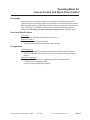
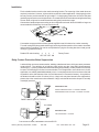
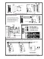
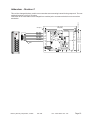
1
SR-10K
Mag-Stripe Access System
Users Guide
Mercury Security Corporation, © 2005
SR-10K
Doc. 10107-0007 Rev 1.04
Page 1
Table of Contents
Section
Page
Overview
3
Quick Start and Configuration Planning
5
Programming Guide
6
Operating Mode Specifications
10
Mode 1: Basic Access Control with Door Monitoring
10
Mode 2: Restricted Access Control with Door Monitoring
11
Mode 3: Access Control and Alarm Panel Control
12
Mode 4: Restricted Access and Alarm Panel Control
13
Mode 5: "Supervisor" Controlled Restricted Access
14
Mode 6: "Two Door" Access Control
14
Mode 7: Access Control with "Door Bell" Feature
15
Mode 8: Dual Output Toggle on Valid Access
15
Installation
16
Maintenance
17
Specifications
17
Dimensions and Typical Configuration Diagrams
18
Addendum: Revision C Circuit Board Dimensions
19
This device complies with part 15 of the FCC Rules. Operation
is subject to the following two conditions: (1) This device may
not cause harmful interference, and (2) this device must
accept any interference received, including interference that
may cause undesired operation.
Mercury Security Corporation
Mercury Security Corporation, © 2005
2355 MIRA MAR AVE. LONG BEACH, CA 90815-1755
(562) 986-9105, FAX (562) 986-9205
www.mercury-security.com
SR-10K
Doc. 10107-0007 Rev 1.04
Page 2
OVERVIEW
Description
The SR-10K is a complete stand-alone access controller, using either magnetic-stripe
cards or cipher (keypad) codes for identifying valid users.
The Card Reader with Keypad and the Interface Module are the SR-10K system's
major components. Separating the door control and other interface connections not
only simplifies the installation, but it greatly improves security by placing the door strike
relay inside the protected area.
The SR-10K offers unparalleled versatiltiy in its class. The investment an installer makes
in learning the SR-10K is greatly rewaded by the number of different applications that
can be solved by the SR-10K.
And cerainly not least, unlike other strictly stand-alone access controllers, the SR-10K
supports expansion to multiple readers at a site.
Programming
A Master Card places the SR-10K into programming mode. Commands are entered via
the keypad on the SR-10K reader. In some cases the entry of user cards may also be
required. A buzzer and two bicolor LEDs provide immediate feedback to the operator.
Card Database Options
The SR-10K supports three different card database modes:
1 - RANDOM mode, supports up to 100 users (factory default):
This mode allows the use of any magnetic stripe card with standard 'track-2' encoding, such as the 'MS-SR10CC25', pre-encoded packs of 25 cards, or cards from
many other access systems, or even bank cards.
Cards are added into 'user slots' by reading the card at the time of enrollment.
Individual or a block of 'user slots' may be deactivated.
2 - BLOCK mode, supports up to 1,600 users:
This database mode requires that all cards are encoded as a set. (Block orders are
typically shipped within a week of the order). Add-on orders can specify an existing
block number and a continuation point. The activation and deactivation of block
cards may be done without the cards and may be performed either individually or in
blocks.
3 - 'FACILITY CODE' mode, there is no limit to the number of users supported,
since the SR-10K is not checking for a unique code:
This mode is useful for low security applications where access cards are already in
use. The number of leading card digits to check is configured from zero to 9 digits.
Setting the number of card digits to check to 'none' causes the SR-10K to accept
any magnetic stripe card as a valid user- also known as the ATM Mode, used to
accept 'any bank card'.
An additional setting allows the SR-10K to skip up to 15 card digits before assembling the facility code. This feature is used in case the facility code does not start at
the beginning of the card.
Mercury Security Corporation, © 2005
SR-10K
Doc. 10107-0007 Rev 1.04
Page 3
OVERVIEW, continued
Cipher Codes
The SR-10K supports up to 10 cipher codes. Each code is one to six digits in length shorter codes are terminated with the '#' key. Cipher codes, like cards, are assigned a
User Level, and like cards, may cause different output relay action depending on the
direction of the code entry. See the next two sections for more details.
User Levels
Each card and cipher code is assigned a User Level from 1 to 3. The User Level, along
with the selected Operating Mode, determines the result of the card or cipher entry. For
example, Level 1 users cannot activate the door relay in some modes unless an input
sees a closed contact.
Operating Modes
The versatility of the SR-10K is based on its ability to configure the function of its inputs
and relays to suit different applications.
The action performed on the door strike relay, for example, depends on the direction of
the card (or cipher code) entry, on the User Level, and possibly on the state of one of the
inputs. In addition, the color of the upper reader LED may display the status of an external device connected to an input, such as an alarm panel's armed/disarmed indicator.
An Operating Mode is a collection of these functions intended for a specific application.
The Operating Modes are described in detail later in this document.
Multi-Reader Sites
Up to 16 SR-10K's may be linked via a '2-wire' cable. Configuration, card, and cipher
code database settings can all be made at just one reader and copied to other SR10K's using simple keypad commands. Modifications can still be made at each reader
in cases, for example, where the databases are not identical at every reader.
The data link uses the RS-485 interface standard, allowing the total cable run to extend
up to 4,000 feet. The devices must be connected in a 'daisy-chain' configuration. Install
the RS-485 termination jumper, J4, on the first and last units only.
This unique feature bridges the gap between complex computer-based integrated access systems and the simpler, individually programmed stand-alone access controllers.
Additional Information
1. The LED's on the interface board are defined as:
A = Heartbeat and reader status: Fast flash: normal. Slow flash: Reader
communication lost.
B = Flashes when there is activity on the RS-485 communication bus.
2. Jumper J3: not used.
Mercury Security Corporation, © 2005
SR-10K
Doc. 10107-0007 Rev 1.04
Page 4
Quick Start and Configuration Planning
Quick Start
The factory default setting enables the SR-10K to be used immediately, without any
further programming, using the 10 cards shipped with the unit. The database is set to
Random Mode, and the cards are enrolled as Level 1 users in slots 01 through 10.
Additional cards are enrolled using Command 10, and Cipher codes may be added
using Command 15. Command 32 sets the door strike relay pulse time.
Configuration Planning
The most important selections are the Card Database Mode and the Operating Mode.
Card Database Mode Selection (Command 93)
The 'Random' Database Mode offers great versatility because it allows the use of just
about any magnetic stripe card. Leave the SR-10K in this mode if the number of users
will not exceed 100.
On the other hand, select the 'Block' Card Database Mode right away if the number of
users may exceed 100, because changing database modes deletes all current entries.
Operating Mode Selection (Command 95)
Select the operating mode best suited to the particular site by evaluating the User
Level functions, the input and auxiliary output functions of each available operating
mode. The selected operating mode determines the installation wiring details and User
Level assignment.
Lost Master Card
Follow the steps outlined below to set a new Master Card in case the current Master
Card is lost:
- remove power from the SR-10K
- install the jumper in position 8
- apply power for a few seconds, then remove it
- remove the jumper from position 8
- apply power to the SR-10K: the old Master Card has been erased!
- add the Master Card using Command 91
(With no valid Master Card, the SR-10K remains in the Programming Mode with the
lower LED set to amber, until a Master Card is set. In fact, only Command 91 is
accepted until the new Master Card is set.)
Interpreting the LED and Buzzer Indicators
Normal operation - the upper LED is ON steady red or green:
The lower LED flashes green briefly following the entry of a valid card or ciper code. A
red flash along with three short beeps indicate an invalid entry attempt.
Programming mode - the lower LED is ON steady green (amber if no Master Card)
The upper LED is OFF if the SR-10K is ready for a new command (wait for '*' key)
The upper LED flashes red while waiting for keypad data entry, and is flashing green
while waiting for card entry.
A single beep echoes a key entry, a double beep indicates the completion of a 'field'
(each line on the command spec section is a field). Three beeps indicate an error
condition. A long beep indicates proper completion of a command.
Mercury Security Corporation, © 2005
SR-10K
Doc. 10107-0007 Rev 1.04
Page 5
SR-10K Programming Guide
The COMMAND ENTRY MODE is selected by passing a valid MASTER card through the reader.
The intergral keypad allows direct data entry on the SR-10K.
The "*" key is used to start a new command entry. The '#' key terminates field entry. For example,
selecting user slot 3 for the the 4-digit user slot entry in Command 20 can be entered as 4 digits:
'0','0','0','3', or it may be entered as '3', '#'.
A single short beep indicates the acceptance of a digit, a double beep indicates the acceptance of
a field. Three short beeps indicate that the command aborted due to an error. One long beep
indicates succesful completion.
RANDOM and Facility Code Database Mode Commands (Commands 10 through 13)
Use these commands to manage the card holders if the RANDOM database mode was selected
Command 93 set to mode "0" - this mode is the facory default.
Command 10 - Add card(s)
* 1 0
1-3
0-9
0-9
user card
( user card
* 0-9
#
- select Command 10
- select the user level: 1, 2, or 3
- select the user number: 00 to 99
- read the card to be added in that slot
- additional cards will be added into successive slots )
- any other action quits the "add loop"
Command 11 - Delete a card, using the user slot
* 1 1
- select Command 11
0-9
0-9
- select the user number: 00 to 99
Command 12 - Delete a card, using the card
* 1 2
- select Command 12
user card
- read the card to be deleted from that slot
Command 13 - Delete a range of cards
* 1 3
- select Command 13
0-9
0-9
- select the first user number to delete: 00 to 99
0-9
0-9
- select the last user number to delete: 00 to 99
Mercury Security Corporation, © 2005
SR-10K
Doc. 10107-0007 Rev 1.04
Page 6
CIPHER CODES Related Commands (Commands 15 through 17)
Up to 10 cipher codes may be defined (user slots 0 through 9). Each cipher code may be from 1 to
6 digits long. Cipher codes shorter than 6 digits are terminated with the "#" key. Just like cards can
produce different results when read "upward", cipher codes can be entered in the "reverse" direction.
For example, cipher code "123" entered as "3", "2", "1", "#" will produce the action specified for
"reverse" entry of a user having the User Level assigned to cipher code "123".
Command 15 - Add Cipher Code(s)
* 1 5
- select Command 15
(
1-3
0-9
0-9 ( 0-9 ) #
0-9, 0-9
#
* #
- select the user level: 1, 2, or 3
- select the user number: 0 to 9
- enter a 1 to 6 digit cipher code, end with '#'
- additional codes will be added into successive slots )
- any other action quits the 'add loop'
Command 16 - Delete a cipher code
- select Command 16
* 1 6
0-9
- select the user number to delete: 0 to 9
Command 17 - Delete a range of cipher codes
* 1 7
- select Command 17
0-9
- select the first user number to delete: 0 to 9
0-9
- select the last user number to delete: 0 to 9
BLOCK Database Mode Commands (Commands 20 through 23)
Use these commands to manage the card holders if the BLOCK database mode was selected
(Command 93 set to mode "1"). The block number is set by Command 94.
Command 20 - Add a card (activate a user)
* 2 0
- select Command 20
1-3
- select the user level (1, 2, or 3)
0-1
0-9
0-9
0-9
- enter the user slot to activate (0000 through 1599)
Command 21 - Delete a card (deactivate a user)
* 2 1
- select Command 21
0-1
0-9
0-9 0-9 - enter the user slot to deactivate (0000 through 1599)
Command 22 - Add a range of cards (block activate)
* 2 2
- select Command 22
1-3
- select the user level (1-3)
0-1
0-9
0-9 0-9
- enter the first user slot to activate (0000 through 1599)
0-1
0-9
0-9 0-9
- enter the last user slot to activate (0000 through 1599)
Command 23 - Delete a range of cards (block deactivate)
* 2 3
- select Command 23
0-1 0-9
0-9
0-9
- enter the first user slot to delete (0000 through 1599)
0-1 0-9
0-9
0-9
- enter the last user slot to delete (0000 through 1599)
Mercury Security Corporation, © 2005
SR-10K
Doc. 10107-0007 Rev 1.04
Page 7
Configuration Settings (Commands 31through 34)
Command 31 - Set the Door Held Open Time
* 3 1
- select Command 31 (from door opening to held open alarm)
0-9
0-9
- select the held open time: 00 to 99 seconds
Command 32 - Set the Door Strike Relay Pulse Time (Output K1)
* 3 2
- select Command 32
0-9
0-9
- select the strike pulse time: 00 to 99 seconds (+1/2 second)
Command 33 - Set the Auxiliary Relay Pulse Time (Output K2)
* 3 3
- select Command 33
0-9
0-9
- select the pulse time for Output K2: 00 to 99 seconds (+1/2 second)
Command 34 - Set the Auxiliary Relay's Pulse Time (Output K2)
* 3 4
- select Command 34
1 or 2
- select the pulse type: 1 for normal, 2 for intermittent output
Configuration and Database Copy Commands (Commands 41through 44)
The following commands allow the configuration and database to be copied from one SR-10K to
another SR-10K. These commands transfer the selected database elements from the SR-10K where
the command is being entered to the SR-10K whose address is specified in the command.
The SR-10K addresses are set by installing the jumper pattern for the desired address on the Interface Module as shown on the installation diagram.
The color of the upper LED is set to flashing amber for the duration of the the data transfer. Periodic
short beeps are used by longer transfers to indicate "transfer in progress". The transfer of the entire
"block mode" card database (1,600 users) may take up to 1 minute.
The completion of a succesful transfer is indicated with the "long-beep". A transfer error condition is
signalled with three short beeps along with a red flash on the upper LED. A transfer error is caused
by either incorrect wiring, or by incorrect jumper settings. Notice: the transfer commands are not
'broadcast'; each SR10K must be set to a unique address 0 to 15.
Command 41 - Copy the Configuration settings only - no card or cipher databases
* 4 1
- select Command 41 (copies seetings enterd with commands 31-34, and 91-95)
0-9
0-9
- select the address of the SR-10K to copy the data to - 00 to 15
Command 42 - Copy the Cipher Database only
* 4 2
- select Command 42 - copies cipher users 0 through 9
0-9
0-9
- select the address of the SR-10K to copy the data to - 00 to 15
Command 43 - Copy the Card Database only
* 4 3
- select Command 43 - copies users 00 through 99, or through 1599
0-9
0-9
- select the address of the SR-10K to copy the data to - 00 to 15
Command 44 - Copy ALL: Configuration Settings, Card and Cipher databases
* 4 4
- select Command 44 - combines Commands 41, 42, and 43
0-9
0-9
- select the address of the SR-10K to copy the data to - 00 to 15
Mercury Security Corporation, © 2005
SR-10K
Doc. 10107-0007 Rev 1.04
Page 8
System Configuration Settings (Commands 91through 95)
Command 91 - Set a New MASTER Card
* 9 1
- select Command 91
1 or 2
- select which Master Card to change: 1 or 2
new card
- read the card to set as the new Master Card
Usage notes:
1 - The second Master Card slot is provided for administrative convenience in cases where the
owner does not wish to maintain the user database: The owner may retain one Master Card and
allow the installer to enroll his card as Master Card 2, thereby letting the installer update the
configuration without having to get the owner's Master Card.
2 - Multiple SR-10K's may be set to the same Master Card
Command 92 - Delete MASTER Card 2
* 9 2
- select Command 92: deletes Master Card 2
Command 93 - Set the Database Mode
* 9 3
- select Command 93
0, 1, 2 or 3
- select the database mode: 0 = Random, 1 = Block, 2 = Facility Code,
(
((
3 = Facility Code with Offset (Skip [n] digits)
0 to 9
0-9
0-9
- only if Facility Code modes: number of Facility Code digits to check
)
- only if Facility Code with Offset: number of digits to skip - 00 to 15 ok
))
Usage notes:
1 - Changing the card Database Mode clears the card database.
2 - Commands 10 through 13 are used with the Random and Faciltiy Code Database Modes
3 - Commands 20 through 23 are used with the Block Database Mode
4 - The Block Number (Command 94) must be set for Block Database Mode operation.
5 - In Facility Code Database Mode, the digit count specifies the the number of card digits to read
and verify. For example, setting the count to '3', the SR-10K uses only the first 3 digits on the
card. Further, setting the count to '0', the SR-10K will accept any properly encoded card,
regardless of the actual data on the card - this configuration is also called the 'ATM Mode'.
In the 'ATM Mode', at least one card must be enrolled in the database. Use
command 10 to enroll a card.
6 - In Facility Code Database Mode, one card must be enrolled for each 'facility code' that is to be
accepted. The cards are enrolled using Command 10.
Command 94 - Set the Block Number
* 9 4
- select Command 94 - required to set if Block Database Mode is used
any user card - enter any user card from the current block
Command 95 - Set the Operating Mode
* 9 5
- select Command 95: determines input/output and user level functions
0-9
0-9
- select the Operating Mode: 01 through 06 (see manual for details)
01 - Basic access control with door alarm monitoring
02 - ...like mode 01, denies User Level 1 based on input contact
03 - Access control with pulsed auxiliary output control (alarm panel)
04 - ...like mode 03, restricts User Level 1 based on input contact
05 - Access control with toggled auxiliary output control
06 - Two-door control
07 - "Door Buzzer" option: *, or #, or REX pulses Output K2
08 - "Dual Output" toggle with restricted access of Level 1 users
Mercury Security Corporation, © 2005
SR-10K
Doc. 10107-0007 Rev 1.04
Page 9
Operating Mode 01:
Access Control with Door Monitoring
Description
Access Control with Door Monitoring provides for basic access control and door use
annunciation.
A downward read of all valid User Cards pulse Output K1, the strike control relay.
The upward read of a Level 2 card toggles the strike control relay, in effect performing a
lock/unlock function. The upward read of a Level 1 card will release an unlocked condition.
Output K2 is pulsed to annunciate improper door use, such as
a) Forced Open condition, which occurs if the door opening was not preceded by the use
of a valid card or an exit request, or
b) Held Open condition, which occurs if the door is kept open longer than the preset open
time.
User Level Specifications
User Level 1
•
•
A downward read will pulse Output K1 (no effect if the door is unlocked).
A upward read will turn off Output K1, ending an unlocked condition.
User Level 2 (and 3)
•
•
A downward read will pulse Output K1 (no effect if the door is unlocked).
A upward read will toggle the state of Output K1, locking or unlocking the door.
Configuration
Input assignments:
•
•
Input I1 is connected to a door contact: closed contact signifies a closed door.
Input I2 is connected to a “request to exit” button. Closing the contact initiates the
request.
Upper LED assignment:
•
The upper LED follows Output K1, the strike control output. Normally RED, the LED
turns GREEN when the door strike is energized (either the timed, or unlocked).
Notes
This mode is the factory set default. It represents the "classic" access controller model
due to the implementation of the door contact and the request to exit sensors and the door
alarm annunciator relay.
The 10 cards included in the original shipment are enrolled as Level 1 users. Be aware,
that if they are modified or any subsequent cards are added as Level 2 users, an upward read will unlock the door - requiring another upward read (by any user Level) to
release the locked condition. Add Level 2 users only if the lock/unlock function is desired.
Mercury Security Corporation, © 2005
SR-10K
Doc. 10107-0007 Rev 1.04
Page 10
Operating Mode 02:
Restricted Access Control with Door Monitoring
Description
Restricted Access Control with Door Monitoring restricts Level 1 user access based on the
status of Input I2 and provides door use annunciation on Output K2.
Level 1 cards are accepted only if the Input I2 sees a closed contact. Level 2 or 3 cards are not
dependent on Input I2.
A downward read of all valid User Cards pulse Output K1, the strike control relay.
The upward read of a Level 2 card toggles the strike control relay, K1, in effect performing a
lock/unlock function. The upward read of a Level 1 card will release an unlocked condition.
Output K2 is pulsed to annunciate improper door use, such as
a) Forced Open condition, which occurs if the door opening was not preceded by the use
of a valid card or an exit request, or
b) Held Open condition, which occurs if the door is kept open longer than the preset open
time.
User Level Specifications
User Level 1
•
•
A downward read will pulse Output K1 only if Input I2 is closed.
A upward read ends an unlocked condition, regardless of the status of Input I2.
User Level 2 (and 3)
•
•
A downward read will pulse Output K1 (no effect if the door is unlocked).
A upward read will toggle the state of Output K1, locking or unlocking the door.
Configuration
Input assignments:
•
Input I1 is connected to a door contact: closed contact signifies a closed door
•
Input I2 is connected to the access control control contact, such as an external timer. User
Level 1 cards are accepted only when a closed contact is presented to this input.
Upper LED assignment:
•
The upper LED follows Input I2, the Access Control Input:
• Open Contact is displayed as RED
• Closed Contact is displayed as GREEN.
Notes
This mode is very similar to Operating Mode 1. The same caution should be observed
regarding the ability to permanently unlock the door:
The 10 cards included in the original shipment are enrolled as Level 1 users. Be aware,
that if they are modified or any subsequent cards are added as Level 2 users, an upward read will unlock the door - requiring another upward read (by any user Level) to
release the locked condition. Add Level 2 users only if the lock/unlock function is desired.
Consider using Operating Mode 4 or 5 if restricted access is required, but the
unlock function is not.
Mercury Security Corporation, © 2005
SR-10K
Doc. 10107-0007 Rev 1.04
Page 11
Operating Mode 03:
Access Control and Alarm Panel Control
Description
The Access Control and Alarm Panel Control configuration provides for basic access
control and gives some users the ability to send a pulse to arm and disarm alarm panels.
Both a downward and an upward read of all User Cards pulse Output K1, the strike control
relay, to allow entry. In addition, the upward read of a Level 2 card pulses Output K2,
allowing the momentary closure to simulate a key-switch input to an alarm panel.
User Level Specifications
User Level 1
• Both downward and upward read will pulse Output K1.
User Level 2 (and 3)
• A downward read will pulse Output K1
• An upward read will pulse both Output K1 and Output K2.
Configuration
Input assignments:
• Input I1 is connected to the armed/disarmed status output from the alarm panel.
• Input I2 is connected to a “request to exit” button. Closing the contact initiates the
request.
Upper LED assignment:
• The upper LED follows Input I1, displaying the status of the alarm panel:
• Open Contact is displayed as RED
• Closed Contact is displayed as GREEN
Mercury Security Corporation, © 2005
SR-10K
Doc. 10107-0007 Rev 1.04
Page 12
Operating Mode 04:
Restricted Access Control and Alarm Panel Control
Description
Restricted Access Control and Alarm Panel Control provides restricts Level 1 user access
based on the status of Input I2 and it gives some users the ability to arm/disarm alarm panels.
Level 1 users are accepted only if Input I2 sees a closed contact. Level 2 or 3 users are not
dependent on Input I2.
Both a downward and an upward read of all valid users pulse the strike control relay. In addition,
the upward read of a Level 2 card pulses Output K2, allowing the momentary closure to simulate
a key-switch input to an alarm panel.
User Level Specifications
User Level 1
Cards having this User Level are rejected if the contact on Input I2 is open. If the contact on Input
I2 is closed:
• Both downward and upward read will pulse Output K1.
User Level 2 (and 3)
• A downward read will pulse Output K1, allowing entry.
• An upward read will pulse both Output K1 and Output K2.
Configuration
Input assignments:
• Input I1 is connected to the armed/disarmed status output from the alarm panel.
• Input I2 is connect to an external timer and functions as the access control input. User
Level 1 users are valid only when a closed contact is presented to this input.
Upper LED assignment:
• The upper LED follows Input I1, displaying the status of the alarm panel:
• Open Contact is displayed as RED
• Closed Contact is displayed as GREEN
Mercury Security Corporation, © 2005
SR-10K
Doc. 10107-0007 Rev 1.04
Page 13
Operating Mode 05:
"Supervisor" Restricted Access Control
Description
This mode allows Level 2 cards to toggle Output K2, which, connected back to Input I2, restricts
Level 1 users. In this mode, Level 1 cards are accepted only if Input I2 sees a closed contact.
User Level Specifications
User Level 1
Cards having this User Level are rejected if the contact on Input I2 is open. If the contact on Input
I2 is closed:
• A downward read will pulse Output K1.
User Level 2 (and 3)
• A downward read will pulse Output K1, allowing entry.
• An upward read will toggle Output K2.
Configuration
Input assignments:
• Input I1 is connected to the request to exit (REX) contact.
• Input I2 is connect to Output K2 and functions as the access control input. User Level
1 users are valid only when a closed contact is presented to this input.
Upper LED assignment:
• The upper LED follows Input I2, displaying the status of the access control input:
• Open Contact is displayed as RED
• Closed Contact is displayed as GREEN
Operating Mode 06:
"Two-Door" Access Control
Description
This mode allows User Level 1 cards to activate Output K1, User Level 2 cards to activate Output
K2, and User Level 3 cards to activate either Output K1 or Output K2.
User Level Specifications
User Level 1
• Both downward and upward read will pulse Output K1.
User Level 2
• Both downward and upward read will pulse Output K2.
User Level 3
• Downward read will pulse Output K1.
• Upward read will pulse Output K2.
Configuration
Input assignments:
• The inputs are not used in this mode.
Upper LED assignment:
• Output K1 off is displayed as RED,
• Output K1 on is displayed as GREEN
Mercury Security Corporation, © 2005
SR-10K
Doc. 10107-0007 Rev 1.04
Page 14
Operating Mode 07:
Access Control with Door Buzzer Control
Description
Access Control with Door Bell Control operates just like Mode 1, with an additional feature
for using Output K2 for annunciation.
This mode was created for applications where Output K2 is configured to drive a door bell/
buzzer. A valid Level 1 user or a Request to Exit input activation will pulse Output K2 for
about one second, creating the "buzz-in" sound.
Pressing the "*" or the "#" keys will act like a door bell. Pressing either "*" or "#" keys will
cause a double pulse on Output K2, creating a sound pattern easily distinguished from the
normal access or exit cycle.
Access by Level 2 users does not affect Output K2 - creating a "silent" entry.
Refer to Mode 1 description for full operational definition.
Operating Mode 08:
Output Toggle on Valid Access
Description
This mode is intended for applications where the outputs need to be toggled, instead of the
standard momentary pulse operation. Both outputs are toggled.
Level 1 users alter the outputs only if Input I2 sees a closed contact.
The upper LED reflects the state of the outputs.
User Level Specifications
User Level 1
•
A read in either direction will toggle Output K1 and Output K2 only if Input I2 is closed.
(The outputs are not affected if Input I2 is open)
User Level 2 (and 3)
•
A read in either direction will toggle Output K1 and Output K2, regardless of the state of
Input I2.
Configuration
Input assignments:
•
Input I1 is not used.
•
Input I2 is connected to the access control control contact, such as an external timer. User
Level 1 cards are accepted only when a closed contact is presented to this input.
Upper LED assignment:
•
The upper LED follows Output K1 (and Output K2):
• Deenergized output is displayed as RED
• Energized output is displayed as GREEN.
Mercury Security Corporation, © 2005
SR-10K
Doc. 10107-0007 Rev 1.04
Page 15
Installation
Find a suitable location to anchor the reader mounting bracket. The mounting of the reader does not
require a junction box. However, rigid conduit is required for outdoor application. A single gang junction
box may used to provide transition to rigid conduit. If a single gang junction box is used, a wall plate
(optional) may be used to cover the junction box. The reader is then secured to the mounting bracket using
a screw. Refer to figures for reader dimensions and typical junction box usage.
Connect door hardware/power according to the configuration selected. Wires of 22AWG or larger are
recommended for field wiring. See local electrical code.
Coat reader connector with the silicone grease supplied to seal off moisture for outdoor mounting.
To avoid having ESD (electrostatic discharge) interfering with the operation of the reader, the reader
casing shall be grounded. This can be accomplished be tying the mounting bracket to earth ground
locally (e.g. grounded conduit).
Reader DIP switch setting:
4
3
2
1
OFF OFF OFF ON
Factory Preset.
Relay Contact Protection/Noise Suppression
Load switching can cause contact transfer, welding, and abnormal wear, which can cause premature
contact failure. The switching of an inductive load (strike) can also cause EMI (electromagnetic
interference). To prolong contact life and increase total system reliability, contact protection circuit must
be used. The following two circuits are recommended. For DC application, use a diode circuit; for AC
application, use a MOV (metal oxide varistor) circuit. Locate the protection circuit as close to the load
as possible, as the effectiveness of the circuit will decrease if it is located to far away. As a guideline,
the distance should be within 12 inches (30 cm). Mag Locks may have internal noise suppression,
please refer to the manufactures documentation. Mag Locks should be wired to Output K1 normally
closed (NC) terminal.
DIODE SELECTION:
+ −
DIODE CURRENT RATING > 1X STRIKE CURRENT
DIODE BREAK DOWN VOLTAGE : 4X STRIKE VOLTAGE
DIODE 1N4001 (50V/1A) TYPICAL
AC
AC STRIKE
MOV SELECTION:
VOLTAGE RATING > Vac RMS
FOR 24Vac STRIKE, PANASONIC ERZ-C07DK470
Mercury Security Corporation, © 2005
SR-10K
Doc. 10107-0007 Rev 1.04
Page 16
Maintenance
The SR-10K readers are designed to provide continuous service with minimal routine maintenance.
However, contaminants (such as magnetic oxides from badges and dirt) tend to accumulate on the
read head. Without regular cleaning, these contaminants will shorten the read head life and increase
the probability of card read error. A maintenance schedule should be developed base on the card
reader environment (dirty or clean) and the usage frequency (light traffic or heavy traffic). Extreme
case may require daily cleaning.
Head cleaning may be done by using disposable, pre-saturated magnetic head cleaning card. These
cards are readily obtainable from a number of sources (e.g. Clean Team Co. 800-888-8830,
www.cleanteam.com; KIC Products, 207-514-7030, www.kicproducts.com; System ID, 1-888-6484452, www.systemid.com).
The reader exterior surface is covered with high strength polymer and polyester membrane. It may be
cleaned with a soft cloth and mild detergent if required.
Specification:
The reader/Interface are for use in low voltage, class 2 circuits only.
Electrical:
Voltage 12 Vdc (10.2 to 13.8 Vdc)
Current 200mA
Relay contacts- K1, 5A@30Vdc; K2, 1A@30Vdc
Distance between reader/interface - 500' (152m) max., 22AWG
RS-485 Comm. Cable - 4,000' (1,219m) max. 24AWG, 120 ohm.
Mechanical:
Reader:
Dimension Weight -
1.95" (50mm)W x 1.30" (33mm)H x 5.50" (140mm)L
10 oz. (284 g) nominal
Interface:
Dimension Weight -
3.25" (83mm)W x 2.9" (74mm)L x 1.4" (36mm)H
4 oz. (120 g) nominal
Environmental:
Temperature:
Humidity:
-55 to +85 degrees C, storage
-40 to +75 degrees C, operating
Reader- 100% RHNC; Interface- 95% RHNC
WARRANTY
Mercury Security Corporation warrants that the product is free from defects in material and workmanship under
normal use and service for two years from factory shipment. Mercury Security Corporation assumes no
responsibility for products damaged by improper handling or installation. This warranty is limited to the repair
or replacement of the defective unit.
There is no expressed warranties other than set forth herein. Mercury Security Corporation does not make,
intends, nor does it authorize any agent or representative to make any other warranties, implied warranties, and
expressly excludes and disclaims all implied warranties of merchantability of fitness for a particular purpose.
Returned units are repaired or replaced from a stock of reconditioned units. Returns must be accompanied
by a return authorization number obtained form customer service, a purchase order and prepaid postage.
LIABILITY
The card readers should only be used to control exits from areas where an alternate method for exit is available.
This product is not intended for, nor is rated for operation in life-critical control applications. Mercury Security
Corporation is not liable under any circumstances for loss or damage caused by or partially caused by the
misapplication or malfunction of the product. Mercury Security Corporation's liability does not extend beyond
the purchase price of the product.
Mercury Security Corporation, © 2005
SR-10K
Doc. 10107-0007 Rev 1.04
Page 17
1.4 [36]
1.3 [33]
2.9 [74]
2.6 [66]
3.3 [84]
5.5 [140]
2 X Ø0.18 [4.5]
HOLES
2.0 [50]
Reader and Interface Dimensions
3.25 [83]
Reader to Interface Connection:
Connect the Reader to the Interface
Module using the straight 6-conductor
modular cable. DO NOT use crossover cable. Maximum distance
between reader and interface is 500
feet using 22AWG wires.
6-COND. STRAIGHT
J2 Jumpers
Strike
JUMPER SETTING
NC
K1
C
NO
NO
NC
K2
C
Forced Open,
Held Open
Alarm Buzzer
+
12V
GND
I2
I2
Exit Request
I1
I1
Door Contact
Typical Wiring Configuration
Communication Wiring: Maximum total cable length - 4,000 ft [1,200 m], 24 AWG
TO ADDITIONAL
SR−10K
SR−10K
SR−10K
PRINTER INTERFACE
(DISCONTINUED)
Set each interface to unique address. Install RS-485 termination jumper, J4, on the first and last units only.
Mercury Security Corporation, © 2005
SR-10K
Doc. 10107-0007 Rev 1.04
Page 18
Addendum - Revision C
0.20 [5.1]
This revision changed the door module to accommodate screw mounting instead of using snap track. The new
module dimension is 4.25 x 2.75 inches.
Connection to the card reader is also changed from modular jack to a screw terminals for more convenient
termination.
4.25 [108.0]
0.20 [5.1]
NC
C
GND
BZR
NO
LED
+12V
G
J4
TR-
K2
C
+12V
2.75 [69.9]
NC
DAT/D0
2.35 [59.7]
NO
CLK/D1
TR+
PIN 1
K1
GND (BLK)
BZR (ORG)
LED (BRN)
CLK (WHT)
DAT (GRN)
12V (RED)
3.85 [97.8]
I2
SG
I2
J2
I1
I1
J3
Mercury Security Corporation, © 2005
SR-10K
B A
Doc. 10107-0007 Rev 1.04
Page 19