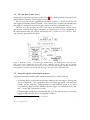
1
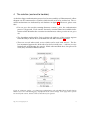
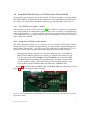
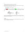
A fix for the firmware v. 3.xx problem
in Davis Instruments Corp. weather stations
© Torkel M. Jodalen
annoyingdesigns.com
December 29, 2014
Abstract
This document describes how to overcome the ”serial line lockdown” introduced by Davis Instruments Corp. in firmware versions 3.00, 3.12 and 3.15 for
the Vantage Pro2 (VP2) series of weather stations and firmware version 3.00 for the
Vue series of weather stations. The fix is based on the Atmel AVR ATtinyX51 series
microcontroller. The document also provides examples of how Davis Instruments
Corp. deals with criticism, user feedback and market communication related to
undocumented product updates.
Introduced in 2012, the green dot data logger requirement2 dramatically changed
long-established functionality of these popular weather stations. The unannounced
change caused a number of problems for users of original Davis equipment, thirdparty equipment and users relying on access to the console serial line. Unfortunately, Davis Instruments Corp. has repeatedly ignored customer feedback and
requests to have the firmware-imposed limitations removed.
This document is an attempt to document the new ”original data logger requirement” introduced in firmware versions 3.00 and later, as Davis evidently will
not comment truthfully on the problems they know this ”feature” may cause to
end-users.
The unfortunate result of Davis Instruments Corp. product development.
1
2
ATtiny25/ATtiny45/ATtiny85.
Also known as ”the original data logger requirement”.
Disclaimer
The author assumes no responsibility for your use of information contained in this
document. Experiment entirely at your own risk.
The author does not represent Davis Instruments Corp. Likewise, the author
does not have any commercial interests in Davis Instruments Corp. or any other
companies or products mentioned in this document.
All trademarks remain the property of their respective holders, and are used
only to identify the products mentioned. Their use in no way indicates any affiliation between the author and the holders of the said trademarks.
No Davis products were hurt or damaged beyond repair while these experiments were carried out.
Quoted prices are in USD unless otherwise noted.
Caution
Never connect anything to the rear expansion connector of the console while power
is still applied to the unit. To safely connect or disconnect anything, remove the external power plug and at least one of the batteries — and let the internal capacitator
discharge.
Pressing the 2ND button twice to activate the LCD backlight will significantly
reduce the time it takes for the capacitator to discharge. The LCD should be completely blank before anything is connected to or disconnected from the expansion
connector.
DO NOT CONNECT the console serial line directly to a PC or any other equipment not known to use 3.3V signal levels. In most cases a level converter such as
the SparkFun FTDI basic breakout, 3.3V version (SparkFun product # DEV-09873 @
$14.95) is required.
http://meteo.annoyingdesigns.com
ii
Contents
1
Introduction
1.1 The Davis Vantage Pro2 series
1.2 Typical station setup . . . . .
1.3 Original Davis data loggers .
1.4 Third-party data loggers . .
.
.
.
.
.
.
.
.
.
.
.
.
.
.
.
.
.
.
.
.
.
.
.
.
.
.
.
.
.
.
.
.
.
.
.
.
.
.
.
.
.
.
.
.
.
.
.
.
.
.
.
.
.
.
.
.
.
.
.
.
.
.
.
.
.
.
.
.
.
.
.
.
.
.
.
.
.
.
.
.
.
.
.
.
.
.
.
.
.
.
.
.
.
.
.
.
.
.
.
.
.
.
.
.
.
.
.
.
.
.
.
.
.
.
.
.
.
.
.
.
2
2
2
3
4
2
The green dot data logger problem
3
A look inside the Davis units
3.1 The console serial line . . . . . . . . . . . . . . . . . . . . . . . . .
3.2 So, how does it work, then? . . . . . . . . . . . . . . . . . . . . . .
3.3 Demystifying the authentication process . . . . . . . . . . . . . .
3.3.1
An introduction to the Serial Pheripheral Interface (SPI) .
3.3.2
Particulars from the AT45DB011 datasheet . . . . . . . .
3.3.3
Logic analyzer findings . . . . . . . . . . . . . . . . . . .
3.3.4
Having a chat with a green-dot Davis data logger . . . . .
.
.
.
.
.
.
.
.
.
.
.
.
.
.
.
.
.
.
.
.
.
.
.
.
.
.
.
.
.
.
.
.
.
.
.
.
.
.
.
.
.
.
.
.
.
.
.
.
.
.
.
.
.
.
.
.
.
.
.
.
.
.
.
6
7
8
8
9
10
11
13
The solution (and end to troubles)
4.1 The next few steps . . . . . . . . . . . . . . . . . . . . . . . . . . .
4.2 Selecting a microcontroller . . . . . . . . . . . . . . . . . . . . . .
4.3 A simple BASCOM-AVR implementation for the ATtiny25/45/85
4.4 A different BASCOM-AVR implementation for the ATtiny85 . .
4.5 Using BASCOM-AVR with the STK500 and the ATtiny25/45/85 .
4.5.1
The STK500 User Guide — read it! . . . . . . . . . . . . . .
4.5.2
Setup of the STK500 for 8-pin devices . . . . . . . . . . .
4.5.3
The MCU programming process . . . . . . . . . . . . . .
4.6 Testing the MCU after programming . . . . . . . . . . . . . . . .
4.7 Wiring the programmed MCU to the Vantage Pro2 console . . . .
.
.
.
.
.
.
.
.
.
.
.
.
.
.
.
.
.
.
.
.
.
.
.
.
.
.
.
.
.
.
.
.
.
.
.
.
.
.
.
.
.
.
.
.
.
.
.
.
.
.
.
.
.
.
.
.
.
.
.
.
.
.
.
.
.
.
.
.
.
.
.
.
.
.
.
.
.
.
.
.
.
.
.
.
.
.
.
.
.
.
16
17
17
18
18
23
23
23
24
25
26
Implications and complications
5.1 Product names/versions
5.2 Design considerations . .
5.3 A need for greed . . . . .
5.4 Email correspondence . .
5.5 Social media . . . . . . .
4
5
6
5
.
.
.
.
.
.
.
.
.
.
.
.
.
.
.
.
.
.
.
.
.
.
.
.
.
.
.
.
.
.
.
.
.
.
.
.
.
.
.
.
.
.
.
.
.
.
.
.
.
.
.
.
.
.
.
.
.
.
.
.
.
.
.
.
.
.
.
.
.
.
.
.
.
.
.
.
.
.
.
.
.
.
.
.
.
.
.
.
.
.
.
.
.
.
.
.
.
.
.
.
.
.
.
.
.
.
.
.
.
.
.
.
.
.
.
28
28
28
28
29
30
Et cetera
6.1 Parts list . . . . . . . . . . . . . . . . . . . .
6.2 Reverse-engineered data logger schematic
6.3 Questions and answers . . . . . . . . . . .
6.4 Contact information . . . . . . . . . . . . .
.
.
.
.
.
.
.
.
.
.
.
.
.
.
.
.
.
.
.
.
.
.
.
.
.
.
.
.
.
.
.
.
.
.
.
.
.
.
.
.
.
.
.
.
.
.
.
.
.
.
.
.
.
.
.
.
.
.
.
.
.
.
.
.
.
.
.
.
.
.
.
.
.
.
.
.
.
.
.
.
.
.
.
.
.
.
.
.
31
31
32
33
37
References
http://meteo.annoyingdesigns.com
.
.
.
.
.
.
.
.
.
.
.
.
.
.
.
.
.
.
.
.
.
.
.
.
.
.
.
.
.
.
.
.
.
.
.
.
.
.
.
.
.
.
.
.
.
38
1
1
1.1
Introduction
The Davis Vantage Pro2 series
Despite shortcomings in sensor accurancy3 the Vantage Pro2 series of weather stations,
manufactured by Davis Instrument Corp. of Hayward, CA, USA (from here on referred
to as Davis) have been popular with weather hobbyists for several years. While neither
build quality nor sensor accurancy are the best, there is an abundant range of product
add-ons available — not necessarily having a true or perceived value anywhere near
the MSRPs, but still useful for self-education, local climate monitoring and carrying
out general weather observations. For educational use, the Davis series of weather stations often fit the bill nicely (again, somewhat over-priced — but acceptable), allowing
students to gain hands-on experience in environmental data collection, data extraction
and data analysis.
One of the main advantages of the Davis VP2 series of weather stations has been
the availability of a serial line for access to weather data without resorting to expensive
add-ons such as the original Davis data loggers. In the educational sector, where each
dime is counted at least twice before it is spent, this aspect is indeed of great importance
— possibly even more important than the somewhat questionable sensor accurancy.
1.2
Typical station setup
A typical Davis weather station setup includes the individual outdoor and/or indoor
sensors, a connector box commonly referred to as the ISS4 — possibly combined with a
radio transmitter, depending on station version — and the indoor display unit referred
to as the console. Several consoles can receive data from one single ISS box.
The console receives data from the ISS, performs some basic calculations, stores
min/max values and calculates derived values. Depending on station configuration, it
also performs a number of other tasks, including alarm output (sensor readings above
or below preset alarm thresholds), acting as a repeater between the ISS and another
console, and sending data to an attached data logger for storage/retrieval. The console
also processes and replies to commands received via its serial line. These commands
are typically issued by software5 running on an attached computer — requesting data
from the console.
Interestingly, Davis documentation [2] states that using the serial line for communication with the outside world ”requires a WeatherLink with Standard Data Logger”. As is
now widely known, this statement is far from correct.
3
Mainly due to low-cost environmental sensors — significant improvements could have been achieved
by using only marginally more expensive parts.
4
Integrated Sensor Suite
5
WeatherLink, Weather Display, WOSPi, weewx, etc.
http://meteo.annoyingdesigns.com
2
1.3
Original Davis data loggers
Data loggers cover two different functions: archiving data from the console and providing a means of communicating with the console from a computer.
The data logger itself contains only a very limited amount of logic: it is mainly made
up of an Adesto Technologies DataFlash chip for data storage and a level converter6 used
for converting the 3.3V signals from the console’s in-system UART7 to more commonly
accepted signals levels — and the other way around, providing safe 3.3V signal levels to
the ATmega128L microcontroller (MCU) found on the main printed circuit board (PCB)
of the console. Apart from that, the data logger doesn’t do much. And even better, it
is fully controlled by the ATmega128L MCU in the console — the data logger just sits
quietly around, doing what it’s told to do.
Original Davis data loggers are delivered with the WeatherLink software, a 1990-ish
software product which won’t leave a lasting impression with anyone. The RS-232
version of the data logger (product # 06510 SER) has a MSRP of $165 as listed on the
Davis website and product catalog [1], somewhat unreasonable for a product made
up of the following parts — even after the cost of R&D efforts has been taken into
consideration:
• The PCB containing the circuit (internally named VantageLINK).
• 2 diodes.
• 3 resistors.
• 8 capacitators.
• 1 Adesto Technologies AT45DB011 DataFlash chip.
• The interface unit (RS-232/serial line level converter, USB interface, ...).
The actual interface components are version dependent.
• The 20-pin console connector.
• The voltage regulator (Seiko S-81230) may be a left-over from a different Davis
product line — the power supply is regulated at 3.0 V, not 3.3 V.
• Exquisite plastic molding, reportedly injection-molded by Lionel Lau, Taiwan.
Apart from the price tag, another well-known issue with the original Davis data
loggers is the amount of heat they produce. Poor thermal design causes the internal
temperature sensor in the console to over-read when an original data logger is attached
to the console, resulting in erroneous indoor temperature readings.
6
7
Or other converter, as appropriate for the data logger variant in question.
Universal Asynchronous Receiver/Transmitter.
http://meteo.annoyingdesigns.com
3
Figure 1: Original Davis data logger — non-green dot version (product # 06510 SER).
Figure 2: Original Davis data logger, under the cover — green dot version (product # 06510 SER).
1.4
Third-party data loggers
In 2012, third-party data loggers with specifications and functionality equal to the original Davis units emerged on the market. Reasonably priced, they offered a most welcome alternative to the overpriced Davis units. Even better, the third-party units were
the result of a community effort driven forward by dedicated Davis customers with a
keen interest in electronics and sharing technical knowledge.
Obviously, this development must have caused interesting reactions at the Davis
HQ in Hayward, CA — perceiving their domain threatened by competitors offering
data logger units at significantly lower prices, they took some unfortunate steps to protect their market share.
Mainstream users probably wouldn’t even know there are third-party applications
and data loggers available, only emphasizing how wasted the Davis efforts at establishing a data logger authentication scheme have been.
http://meteo.annoyingdesigns.com
4
2
The green dot data logger problem
Starting in 2012, new Davis data loggers suddenly shipped with a green dot sticker
attached to the enclosure, hence the unofficial term green dot data loggers. The same
green dot sticker started appearing on console enclosures, indicating consoles shipping
with the new firmware version 3.00. For the Vantage Pro2 series of weather stations,
the firmware version made a remarkable jump from v. 1.90 to v. 3.00 overnight — and
later to version 3.12, the latter also being made available for updating existing consoles
running firmware version 1.90.
To cut a long story short: a green dot console requires a green dot data logger. A green
dot data logger can be used with a non-green dot console, but not the other way around.
The green dot data logger requirement effectively puts an end to the use of thirdparty data loggers with consoles manufactured from mid-2012 onwards. Also, the serial line remains ”locked down” until an original Davis data logger is attached. In short,
this means that:
• It won’t be possible to re-use an old (non-green dot) data logger with a new green
dot console.
• If, for some reason, a user has a non-green dot console replaced with a new green
dot console (warranty replacement, etc.), a new data logger may also be required.
Customers in the US are only faced with the trouble of getting in touch with Davis
for a free replacement logger. Customers outside the US are left on their own.
• Anyone using the serial line for direct access to the console will no longer be able
to do so. As long as the serial line remains locked down, the console will only
output ”LCD OK” during the boot sequence. After that, any command issued via
the serial line will receive a ”NO” reply to indicate that the serial line interface is
not available.
• Attaching a non-green dot data logger to a green dot console will result in the
”INCOMPATIBLE LOGGER” message on the console display, as shown on the
front page of this document.
Figure 3: The green dot enclosure for new data loggers. The green dot is placed inside the plastic wrapping. All new data loggers are of the green dot type, even though they have been shipping without the
fancy green sticker lately (2013-). It is not known whether all new data loggers are now shipping with or
without the green dot sticker.
http://meteo.annoyingdesigns.com
5
3
A look inside the Davis units
Apart from the custom-made LCD display, the Davis Vantage Pro2 console consists of
commonly available electronics parts. The microcontroller running the entire show is
an Atmel ATmega128L [5] loaded with Davis’ own firmware.
The console unit contains a rear expansion connector which is directly wired to
the ATmega128L MCU. Tracing the individual connectors back to the MCU pinout, as
has already been done and documented thoroughly [10], has revealed some interesting
facts. Figures 4 and 5 refer.
Figure 4: Atmel ATmega128L pinout. Note pins 2-3 (serial data) and 10-13 (SPI).
Figure 5: The Davis Vantage Pro2 rear expansion connector, as described by DeKay [10]. NOTE: Pin
numbers/orientation as seen when looking directly at the exposed connector at the rear of the console.
http://meteo.annoyingdesigns.com
6
3.1
The console serial line
Of particular interest on the ATmega128L MCU are the pins used for serial line communication (pins 2, 3 and GND) as well as the SPI8 lines.
Pins 2, 3 and GND are routed directly to the expansion connector at the rear of the
console. The signal logic adheres to the EIA-232 (RS-232) specification, though signal
levels are 3.3V only. As such, a level converter is required for interfacing to a personal
computer, which would otherwise fry the MCU. A number of small computer systems
such as the Raspberry Pi [13] expose a 3.3V serial line, meaning that a direct connection
to the serial line on the Davis console is possible. A level converter may still be required,
refer to the parts list in section 6.1 for details.
The availability of a console serial line is a well-known fact, used by third-party software
and pheripheral equipment developers. Although official Davis documentation states that a
data logger unit is required, it turns out it is not a requirement to access the serial line.
A variety of applications have been developed by users having a desire to add functionality to their consoles: data loggers, interface units, XBee and Bluetooth modules for
wireless data retrieval — just to mention the more common ones. A common denominator is that users want to expand the capabilities of their units, using long-established,
well-known and well-documented features offered by their Vantage Pro2 consoles. This
expandability indicates a good initial design of the console unit, and it is a shame to see
it go only due to poor management decisions at the Davis HQ.
8
Serial Pheripheral Interface.
http://meteo.annoyingdesigns.com
7
3.2
So, how does it work, then?
During power-up (boot sequence) or after a reset9 , the console performs internal checks
and determines whether a data logger is connected.
For non-green dot consoles upgraded to firmware version ≥ 3.12, the serial line and
data logging functions remain available. Users remain free to utilize their third-party
data loggers, old-school Davis data loggers, direct serial line communication, etc.
The new green dot consoles, however, start out on an authentication scheme to ensure that the attached data logger constitutes an original piece of Davis equipment. If
the authentication fails, the console will display the ”INCOMPATIBLE LOGGER” message until it is powered down again.
Figure 6: Firmware version ≥ 3.12 data logger authentication. The authentication only takes place
if the console itself is identified as a green dot console. Firmware version 3.00 has only been shipped
preinstalled on new consoles, whereas version 3.12 can be downloaded to upgrade existing consoles. The
”not applicable” branch is followed when the data logger does not return a valid status code.
3.3
Demystifying the authentication process
A qualified attempt at outlining the authentication process can be made by:
• Assuming that no extra hardware has been added to the data logger. To keep unit
cost at a minimum, Davis equipment does not utilize top-notch environmental
sensors. In line with this, assuming that no extra hardware (such as an Atmel
CryptoMemory chip) has been added to the data logger, as it would increase unit
cost — seems like a good place to start.
• Comparing the components found inside the green dot and the non-green dot data
loggers verifies that the above assumption is correct.
9
By grounding pin 7 (reset) of the expansion connector.
http://meteo.annoyingdesigns.com
8
• Watching the serial line for any activity during the boot sequence reveals that the
serial line is not involved in the authentication process. This leaves the Serial
Pheripheral Interface (SPI) as a promising candidate.
• The Adesto Technologies datasheet for the AT45DB011 DataFlash chip [20] is an interesting read, as it provides several hints of what mechanisms can be employed
in the authentication process — without adding additional hardware components
to the circuitry.
• Hooking up a logic analyzer such as the Saleae Logic16 [15] will quickly reveal the
communication taking place on the SPI lines during the console boot sequence.
• Hooking up a BusPirate [18] and having a chat with the AT45DB011 DataFlash
chip found in the original data loggers aid in extracting interesting data from the
DataFlash chips.
3.3.1
An introduction to the Serial Pheripheral Interface (SPI)
The Serial Pheripheral Interface is used throughout the Davis consoles for communication between different subsystems. The SPI lines are also utilized to authenticate an
attached data logger during the console boot sequence. Another use is to actually write
data to the memory chip in the data logger.
A basic SPI system consists of a master unit and one or more slave units. At least
three wires are required for a basic SPI system consisting of only one master and one
slave. For systems consisting of one master unit and multiple slave units, four wires
are required. The SPI signal names are as follows:
MOSI Master Out, Slave In — data carrying line.
MISO Master In, Slave Out — data carrying line.
CLK Clock pulse — provided by the master unit.
SS Slave Select (also known as CS — Chip Select) — used to ”address” one particular slave unit.
Readers unfamiliar with the SPI can find numerous informative articles online. A
good starting point is the Wikipedia article [23] on the Serial Pheripheral Interface. Note
that SPI signals are routed ”straight through” — MOSI from the master should be
routed to MOSI on the slave, MISO from the slave should be routed directly to MISO
on the master, etc.
In the case of Davis consoles, the ATmega128L MCU takes the role as master, whereas
the AT45DB011 DataFlash chip steps into the slave role. That said, the fact that Davis resorts to fairly standard communication routines for chip-to-chip communication inside
their consoles only aids the process of determining the exact nature of the data logger
authentication process.
http://meteo.annoyingdesigns.com
9
3.3.2
Particulars from the AT45DB011 datasheet
The Adesto Technologies AT45DB011 1Mbit DataFlash chip [20] found in original Davis
data loggers contains the storage space for logging weather observations from the console.
The AT45DB011 DataFlash chip is well documented and it even supports a limited
instruction set. The instruction set is typically used to store and retrieve data and to
carry our related ”housekeeping functions”.
Each DataFlash chip comes with a unique, factory-programmed 64-byte device identifier which cannot be modified. The chip also has what is known as a programmable
64-byte security register. The security register can be programmed once — once programmed, it cannot be changed. The original Davis data loggers all come with programmed security registers, in which each of the 64 bytes has been calculated during
the ”burn in” stage of production.
It is noteworthy that even non-green dot data loggers come with programmed security registers in the AT45DB011 DataFlash chips. The values in the security registers of
the non-green dot units are obviously calculated in a way which will not ensure validation of the data loggers when used with green dot consoles.
For simplicity, further references to the security register will regard the device identifier (64 bytes) and the actual security register (64 bytes) as one single 128-byte entity.
OpCode
Req’d Description
0xD7
0x77
0x9F
Yes
Yes
No
Return chip status. Returning 0x8C will do the trick.
Return security register, 128 bytes.
Return manufacturer ID and data density. Values 0x1F and
0x22 identify the AT45DB011 DataFlash chip.
Table 1: Relevant opcodes for the AT45DB011 DataFlash chip [20]. The ”required” field indicates which
opcodes are required for data logger authentication.
Although not required to authenticate an original Davis data logger, the 0x9F opcode returns 0x1F (binary 00011111) which identifies Adesto Technologies as manufacturer and 0x22 (binary 00100010) which indicates what data density is found on
the (1 Mbit) DataFlash chip.
http://meteo.annoyingdesigns.com
10
3.3.3
Logic analyzer findings
Using a logic analyzer such as the Saleae Logic16 [15] hooked up to GND and the MOSI,
MISO, CLK and SS lines between the console and the original Davis data logger reveals which communication is going on there.
The data logger authentication only takes place during the console boot sequence,
either when first powering up the console or after a console reset.
The console starts out by reading the chip status. If the chip status is found acceptable, the entire 128-byte security register is read and verified.
Figure 7: Capturing the SPI communication between the console and the original Davis data logger.
Here the console issues the 0x77 opcode, followed by three required dummy bytes. The AT45DB011
DataFlash chip then replies with the 128 byte values stored in the security register, here starting with
0x9A 0x2F ...
Recommended configuration settings for the Saleae Logic16 logic analyser:
• Four channels enabled: MOSI, MISO, CLK and CS/SS.
• Sample rate of 50 MHz (25 MHz also used with success).
• MSB first.
• 8 bits per transfer.
• Clock high when inactive (CPOL = 1).
• Data valid on clock trailing edge (CPHA = 1).
• Enable line active when low.
Connect the MISO, MOSI, CLK, CS/SS and GND probes to the respective signal
sources — figure 8 refers.
http://meteo.annoyingdesigns.com
11
Figure 8: Bird on the wire: the Saleae Logic16 listening in on the SPI communication between the console
and the original Davis data logger. The AT45DB011 DataFlash chip is the one at the far left of the PCB.
http://meteo.annoyingdesigns.com
12
3.3.4
Having a chat with a green-dot Davis data logger
Using a BusPirate [18] in SPI mode, the AT45DB011 status byte and the security register
can be read from an original Davis data logger. This step is by no means required, but
it can be a useful tool to extract the contents of the securty register in the AT45DB011
DataFlash chip.
The BusPirate is connected to a PC via a USB cable. Use a terminal emulator such
as HyperTerminal (once included in Microsoft Windows distributions) or RealTerm [9] to
communicate with the BusPirate. Serial line communication parameters are 115200-8N-1.
The pins referred to below are numbered as shown in figure 5. Please take note of
the ”orientation” note just below the figure.
BusPirate
Pin name
CS
CLK
MOSI
MISO
3V3 – VPU
GND
Original Davis data logger
Pin name
Pin #
SS
1
SCK
2
MOSI
3
MISO
4
VCC
13/14
GND
15/16
Table 2: Wire routing between the BusPirate header and the original Davis data logger. Also make
a connection from 3V3 to the VPU pin, both on the BusPirate header (BusPirate version 4 users can
probably use the ”e” command instead — refer to the BusPirate documentation [18] for details). Always
keep the SPI wires as short as possible.
The BusPirate needs to be configured with the correct SPI parameters. Note that
the BusPirate command interpreter is case-sensitive. These configuration settings have
proven to work well, although some of them don’t really make any sense (commands
listed at left, comments at right):
m
5
1
1
2
1
2
2
Set mode (entering interactive menu)
SPI
Speed: 30 kHz
Clock polarity: idle when low
Output clock edge: active to idle
Input sample phase: middle
CS: /CS
Output type: normal (H=3.3V, L=GND)
W
P
On-board power supply ON
On-board pullup resistors ON
http://meteo.annoyingdesigns.com
13
Then proceed by sending some commands to the AT45DB011 DataFlash chip in the
original data logger and read the return values:
• To read the chip status, which should return 0x8C :
[0xd7 r:1]
• To read the manufacturer ID and device density, which should return the values
0x1F 0x22 0x00 0x00 :
[0x9f r:4]
• To read the entire security register of 128 bytes:
[0x77 0 0 0 r:128]
Figure 9: The BusPirate having a friendly chat with an original Davis data logger. NOTE: The SPI wires
have to be kept short, otherwise it just won’t work.
http://meteo.annoyingdesigns.com
14
Figure 10: The BusPirate doing just what it is supposed to do.
The contents of the security registers of two different Davis data loggers is included
below (also refer to section 6.3):
SECURITY REGISTER VALUES
0x9A 0x2F 0x21 0x35 0x3D
0x18 0x1C 0x63 0x0C 0x31
0x98 0x8C 0x88 0x84 0x80
0xB1 0xCA 0xCE 0xC2 0xC6
0x0B 0x02 0x06 0x0A 0x0B
0x30 0x30 0x4D 0x32 0x36
0x43 0xFF 0xFF 0xFF 0xFF
0xFF 0xFF 0xFF 0xFF 0xFF
from
0x4A
0x00
0x9C
0xDA
0x0E
0x31
0xFF
0xFF
a green dot logger unit (S/N C120701K93LL):
0x98 0xA9 0x21 0x25 0xA5 0x2D 0x2D 0x31 0x9C
0x21 0x04 0x73 0x3D 0x25 0x6F 0x6B 0x77 0x73
0x98 0x94 0x90 0xAD 0xA9 0xA5 0xA1 0xBD 0xB9
0xDE 0xD2 0xD6 0xEB 0xEF 0xE3 0xE7 0xFB 0xFF
0x1F 0x22 0x00 0x00 0x20 0x00 0xFF 0xFF 0xE0
0x38 0x30 0x05 0x30 0x35 0xFF 0xFF 0xFF 0xFF
0xFF 0xFF 0xFF 0xFF 0xFF 0xFF 0xFF 0xFF 0xFF
0xFF 0xFF 0xFF 0xFF 0xFF 0xFF 0xFF 0xFF 0xFF
SECURITY REGISTER VALUES
0x00 0x00 0x53 0xBA 0x7F
0xFF 0x80 0x7F 0xBF 0xFF
0xFF 0xFF 0xFF 0xFF 0xFF
0x51 0x81 0x00 0x00 0x00
0x00 0x00 0x7F 0xFF 0xFF
0xFF 0xFF 0x80 0x7F 0xFF
0x52 0x01 0x52 0x01 0x51
from
0xBF
0xA5
0xFF
0x00
0x80
0xFF
0x81
a non-green dot logger unit (S/N BB1210E72LL):
0xBA 0x80 0x5B 0x01 0x08 0x88 0x80 0x00 0x7F 0xFF
0xFF 0xFF 0xFF 0xFF 0xFF 0xFF 0xFF 0xFF 0x80 0x7F
0xFF 0xFF 0xB8 0x8D 0x30 0x84 0x51 0x81 0x51 0x81
0x54 0xBA 0x7F 0xBF 0xBA 0x80 0x5B 0x01 0x08 0x89
0x7F 0xBF 0xFF 0xA5 0xFF 0xFF 0xFF 0xFF 0xFF 0xFF
0xFF 0xFF 0xFF 0xFF 0xFF 0xFF 0xB8 0x8D 0x33 0x04
0x00 0x00 0x00 0x00 0x55 0xBA 0x7F 0xBF 0xBA 0x80
http://meteo.annoyingdesigns.com
0x39
0x7F
0xB5
0xF3
0xFF
0xFF
0xFF
0xFF
15
4
The solution (and end to troubles)
As the data logger authentication process has been reasonably well documented, a flow
diagram can be constructed to visualize which details need to be worked on. The essential mechanisms are indicated by red shadows in figure 11. However, please note
that:
• For non-green dot consoles running firmware version ≥ 3.12, the authentication
process is bypassed. Each console obviously contains firmware-readable information which identifies the execution environment as either green dot or non-green
dot.
• The algorithm employed by Davis to derive the 64 bytes of the security register
from the 64-byte device ID was identified in late 2013. Section 4.4 refers.
• There are several other attack vectors which can be used with success. The below mentioned approach is believed to be the least risky one — with no (or very
limited) risk of damaging the console. While other methods have also proved to
work, they will not be discussed here.
Figure 11: Firmware version ≥ 3.xx data logger authentication. The red-shaded boxes identify obvious
attack vectors. The ”start data logging” step depends on the console settings. Some ”page move” opcodes
are issued by the console, but the results (or lack thereof) are ignored.
http://meteo.annoyingdesigns.com
16
4.1
The next few steps
From here on, it’s all a matter of:
• Chosing a microcontroller for the implementation.
• Chosing a compiler/IDE and other programming tools for the implementation.
• Programming the microcontroller.
• Wiring the microcontroller to the console.
4.2
Selecting a microcontroller
There is a huge variety of microcontrollers available, many of which can be used to
reply to the commands from the Davis console. Of the more interesting ones are the PIC
family from Microchip and the AVR series from Atmel. While the everlasting AVR vs.
PIC discussion is better left to others, it´s worth noting that:
• Davis makes use of the AVR family of RISC MCUs — the ATmega128L is the
”brain” of the VP2 consoles as well as other Davis consoles.
• There are plenty of reasonably-priced programming devices and compilers available for the AVR family, including Arduino-based programmers.
The fact that an STK500 programmer [6] was already within reach and that knowledge of the AVR platform was already established made it attractive to opt for the AVR
family of MCUs.
Picking the actual MCU requires studies of the units available. While there are
MCUs which come with dedicated SPI pins, such as the ATmega8, these units carry the
drawbacks of a less attractive form factor, they draw more power and have a higher
unit cost than what is really necessary.
MCU
name
ATmega8
ATtiny25
ATtiny45
ATtiny85
Farnell.no
part #
9171380
N/A
1288352
1455162
Newark.com
part #
68T3197
68T3598
68T3729
68T3808
Product
ID
ATMEGA8-16PU
ATTINY25-20PU
ATTINY45-20PU
ATTINY85-20PU
Flash
memory
8 kB
2 kB
4 kB
8 kB
Unit price
(USD)
3.66
1.06
0.95
1.29
Table 3: A selection of relevant AVR microcontrollers. Quoted prices as of July, 2013.
The ATtiny45 [8] is reasonably priced and has plenty of memory for the task at
hand. It comes with an Atmel-specific Universal Serial Interface (USI), which has to be
configured for SPI operation. Atmel application note AVR319 [4] refers.
Both the 10 MHz (denoted ”-10PU” in the product ID) and the 20 MHz (”-20PU”)
versions of the ATtiny25/45/85 have been tested in this project.
http://meteo.annoyingdesigns.com
17
4.3
A simple BASCOM-AVR implementation for the ATtiny25/45/85
The BASCOM-AVR BASIC compiler [12] for Windows is available free of charge10 . While
Atmel Studio [7] and WinAVR [24] are certainly capable of the task (utilizing the C/C++
languages), Atmel Studio requires Micorosoft Visual Studio as a back-end, resulting in a
rather comprehensive software package.
The BASCOM-AVR IDE/compiler requires only some 50 MB of disk space — and
runs considerably faster than Atmel Studio on old-fashioned computers. While the included BASCOM-AVR documentation is comprehensive enough, please note the existence of additional text resources such as [17] and [16].
As it seems, it is only necessary to program a simple11 microcontroller with a program capable of the following tasks:
• Prepare the microcontroller for SPI operation.
• When detecting that the console wants to communicate (CS/SS line pulled low):
– Detect and respond to the return chip status command.
– Detect and respond to the return security register command.
This can all be achieved quite easily with the BASCOM-AVR compiler. Program
listing 1 refers, including a 128-byte security register which was once posted to the
WXForum.net discussion forum [19].
4.4
A different BASCOM-AVR implementation for the ATtiny85
The BASCOM-AVR program shown in code listing 2 is based on the algorithm described by WXForum.net user watson [21] in late 2013. The program will provide a
random device ID and generate the corresponding security register values. Due to
memory (SRAM) requirements, this implementation is not suitable for the ATtiny25
MCU.
The actual implementation has been successfully tested with an original FW version
3.00 VP2 console and the ATtiny85 MCU.
10
In the free/demo version, a program size limit of 4 kB applies — consider obtaining a full version
license, it’s a useful software product which deserves some support.
11
”Simple” as in as simple as possible, i.e. at the lowest possible cost.
http://meteo.annoyingdesigns.com
18
'
'
'
'
'
'
Unlock the Davis VP2/Vue console serial line using the ATtiny25/45/85
Torkel M. Jodalen <[email protected]> - http://www.annoyingdesigns.com
Revised: 2013-10-28
NOTE:
The SECURITY_REGISTER_DATA (128-byte security register) is
defined in the DATA section following the program logic.
$PROG &HFF,&HC1,&HDF,&HFF
' Lock, FuseLow, FuseHigh, FuseExtended
$REGFILE = "ATtiny85.DAT"
' Change as required for ATtiny25/45/85
$HWSTACK = 40
$SWSTACK = 16
$FRAMESIZE = 32
Const CMD_STATUS
= &HD7
Const CMD_SECURITY
= &H77
Const RESPONSE_STATUS = &H8C
Dim I As Byte
Dim COMMAND As Byte
Dim USI_DATA_READY As Bit
' Chip status command
' Dump security register command
' Response to CMD_STATUS
' The infamous loop counter
' Command byte as received from console
' Status flag
' Slave select / chip select
SS Alias PinB.4
' Use PINB for READ, PORTB for WRITE
Config PortB.4 = Input
' This will be a READ-ONLY pin, read from "SS"
Set PortB.4
' Make sure WE don't pull PortB.4 low
' Perform the SPI setup using the ATtiny's USI
Set USICR.USIWM0
' SPI mode
Reset USICR.USIWM1
' SPI mode
Set USICR.USICS1
' External clock (clocked by the ATmega128L in the console)
Reset USICR.USICLK
' External clock
Reset USICR.USICS0
' Positive edge
Set USICR.USIOIE
' Enable counter overflow interrupt
' Enable USI overflow interrupts
On USI_OVF USI_OVERFLOW_INT
Enable USI_OVF
Enable Interrupts
Do
While SS = 1
' Wait for SS low
Wend
' Set up the ATTiny25/45/85 USI for SPI operation (SS has been pulled low)
Config PortB.0 = Input
' PB0 = MOSI
Config PortB.1 = Output
' PB1 = MISO
Config PortB.2 = Input
' PB2 = Clock
' Wait for something to come around
While USI_DATA_READY <> 1
Wend
If COMMAND = CMD_STATUS Then
' Respond to CMD_STATUS
While USI_DATA_READY <> 1
Wend
USIDR = RESPONSE_STATUS
Reset USI_DATA_READY
' NOTE: Code listing continued on next page!
Listing 1: Complete BASCOM-AVR source code listing for the Atmel ATtiny25/45/85. Change the
$REGFILE assignment to indicate the ATtiny model being used (here: ATtiny85).
http://meteo.annoyingdesigns.com
19
ElseIf COMMAND = CMD_SECURITY Then
' Respond to CMD_SECURITY
For I = 0 To 2
' First respond with three dummy bytes as per AT45DB011 specification
While USI_DATA_READY <> 1
Wend
USIDR = &H00
Reset USI_DATA_READY
Next I
For I = 0 To 127
' Then respond with 128-byte security register data
While USI_DATA_READY <> 1
Wend
USIDR = Lookup(I , SECURITY_REGISTER_DATA)
Reset USI_DATA_READY
Next I
End If
' Done communicating, set Hi-Z state on PB1 (MISO) port
Config PortB.1 = Input
Loop
End
' The interrupt routine
USI_OVERFLOW_INT:
Set USI_DATA_READY
COMMAND = USIDR
USISR = &B01_000000
Return
' Indicate data received & ready
' Get one byte from the SPI line
' Reset status register
' Security register data - 128 bytes of known/accepted values
SECURITY_REGISTER_DATA:
Data &H80, &H2D, &H22, &H6F, &H52, &H6F, &H98, &HA9, &H21, &H25,
&H18, &H1C, &H63, &H0C, &H31, &H21, &H2D, &H39, &H90, &HDE,
&H63, &H8C, &H88, &H84, &H80, &H9C, &H98, &H94, &H90, &HAD,
&HB1, &HCA, &HCE, &HC2, &HC6, &HDA, &HDE, &HD2, &HD6, &HEB,
&H0B, &H02, &H16, &H17, &H11, &H15, &H1F, &H22, &H00, &H00,
&H30, &H30, &H4D, &H32, &H36, &H39, &H37, &H31, &H0F, &H1C,
&H3F, &HFF, &HFF, &HFF, &HFF, &HFF, &HFF, &HFF, &HFF, &HFF,
&HFF, &HFF, &HFF, &HFF, &HFF, &HFF, &HFF, &HFF, &HFF, &HFF,
&H5E,
&H94,
&HA9,
&HEF,
&H46,
&H0C,
&HFF,
&HFF,
&H2D,
&H6F,
&HA5,
&HE3,
&H00,
&HFF,
&HFF,
&HFF,
&H2D,
&H6B,
&HA1,
&HE7,
&HFF,
&HFF,
&HFF,
&HFF,
&H31,
&H77,
&HBD,
&HFB,
&HFF,
&HFF,
&HFF,
&HFF,
&HD2,
&H73,
&HB9,
&HFF,
&HAC,
&HFF,
&HFF,
&HFF,
&H39,_
&H7F,_
&HB5,_
&HF3,_
&HFF,_
&HFF,_
&HFF,_
&HFF
Listing 1: Code listing continued from previous page.
http://meteo.annoyingdesigns.com
20
'
'
'
'
'
'
'
'
Unlock the Davis VP2/Vue console serial line using the ATtiny85 and a
random device ID. Using algorithm as described by WXForum.net user
"watson" on November 28, 2013.
NOTE: The ATtiny25 does NOT have sufficient SRAM for this implementation.
Torkel M. Jodalen <[email protected]> - http://www.annoyingdesigns.com
Revised: 2013-11-30
$PROG &HFF,&HC1,&HDF,&HFF
$REGFILE = "ATtiny85.DAT"
' Lock, FuseLow, FuseHigh, FuseExtended
$HWSTACK = 64
$SWSTACK = 16
$FRAMESIZE = 32
Config BASE = 0
Const
Const
Const
Const
Dim
Dim
Dim
Dim
CMD_STATUS
CMD_SECURITY
CMD_DEVICEID
RESPONSE_STATUS
Response(128) As Byte
I As Byte
COMMAND As Byte
USI_DATA_READY As Bit
=
=
=
=
&HD7
&H77
&H9F
&H8C
'
'
'
'
Chip status command
Dump security register command
Manufacturer & Device ID command
Response to CMD_STATUS
' Will contain 128-byte reply to CMD_SECURITY command
' The infamous loop counter
' Command byte as received from console
' Status flag
Declare Function Calculate(ByteNo As Byte) As Byte
' Fill in a random device ID, bytes 64-127
For I = 64 To 127
Response(I) = RND(256)
Next I
' Fill in appropriate security register values, bytes 3-63
For I = 3 To 63
Response(I) = Calculate(I)
Next I
' Fill in a serial number(?), bytes 0-2
Response(0) = &H9A
' 9A 2F 21 are values found in an original
Response(1) = &H2F
' logger. This may or may not be a device
Response(2) = &H21
' serial number. Doesn't seem to matter.
' Slave select / chip select
SS Alias PinB.4
' Use PINB for READ, PORTB for WRITE
Config PortB.4 = Input
' This will be a READ-ONLY pin, read from "SS"
Set PortB.4
' Perform the SPI setup
Set USICR.USIWM0
' SPI mode
Reset USICR.USIWM1
' SPI mode
Set USICR.USICS1
' External clock (clocked by the ATmega128 in the console)
Reset USICR.USICLK
' External clock
Reset USICR.USICS0
' Positive edge
Set USICR.USIOIE
' Enable counter overflow interrupt
' Enable USI overflow interrupts
On USI_OVF USI_OVERFLOW_INT
Enable USI_OVF
Enable Interrupts
Do
While SS = 1
' Wait for SS low
Wend
' Set up the ATTiny85 USI for SPI operation (SS has been pulled low)
Config PortB.0 = Input
' PB0 = MOSI
Config PortB.1 = Output
' PB1 = MISO
Config PortB.2 = Input
' PB2 = Clock
' NOTE: Code listing continued on next page!
Listing 2: Complete BASCOM-AVR source code listing for the Atmel ATtiny85 resulting in a random
device ID and corresponding security register values.
http://meteo.annoyingdesigns.com
21
' Wait for something to come around
While USI_Data_ready <> 1
Wend
If COMMAND = CMD_STATUS Then
' Respond to CMD_STATUS
While USI_DATA_READY <> 1
Wend
USIDR = RESPONSE_STATUS
Reset USI_DATA_READY
ElseIf COMMAND = CMD_SECURITY Then
' Respond to CMD_SECURITY
For I = 0 To 2
' First respond with three dummy bytes as per AT45DB011D specification
While USI_DATA_READY <> 1
Wend
USIDR = &H00
Reset USI_DATA_READY
Next I
For I = 0 To 127
' Then respond with 128-byte security register data
While USI_DATA_READY <> 1
Wend
USIDR = Response(I)
Reset USI_DATA_READY
Next I
End If
' Done communicating, set Hi-Z state on PB1 (MISO) port
Config PortB.1 = Input
Loop
End
' The interrupt routine
USI_OVERFLOW_INT:
Set USI_DATA_READY
COMMAND = USIDR
USISR = &B01_000000
Return
Function Calculate(ByteNo As Byte) As Byte
' Not too elegant --- BASCOM-AVR only accepts one operation per assignment
Local Index As Byte
Index = ByteNo + 64
' 64-127 for device ID
Index = Response(Index) + ByteNo
' Index in DAVIS_DATA matrix
Index = Index MOD 256
' Avoid index out of range
Response(ByteNo) = LookUp(Index, DAVIS_DATA)
End Function
' Lookup table as described by WXForum.net user "watson"
DAVIS_DATA:
$DATA
Data &H00, &H04, &H08, &H0C, &H10, &H14, &H18, &H1C, &H21,
Data &H46, &H42, &H4E, &H4A, &H56, &H52, &H5E, &H5A, &H67,
Data &H8C, &H88, &H84, &H80, &H9C, &H98, &H94, &H90, &HAD,
Data &HCA, &HCE, &HC2, &HC6, &HDA, &HDE, &HD2, &HD6, &HEB,
Data &H18, &H1C, &H10, &H14, &H08, &H0C, &H00, &H04, &H39,
Data &H5E, &H5A, &H56, &H52, &H4E, &H4A, &H46, &H42, &H7F,
Data &H94, &H90, &H9C, &H98, &H84, &H80, &H8C, &H88, &HB5,
Data &HD2, &HD6, &HDA, &HDE, &HC2, &HC6, &HCA, &HCE, &HF3,
Data &H31, &H35, &H39, &H3D, &H21, &H25, &H29, &H2D, &H10,
Data &H77, &H73, &H7F, &H7B, &H67, &H63, &H6F, &H6B, &H56,
Data &HBD, &HB9, &HB5, &HB1, &HAD, &HA9, &HA5, &HA1, &H9C,
Data &HFB, &HFF, &HF3, &HF7, &HEB, &HEF, &HE3, &HE7, &HDA,
Data &H29, &H2D, &H21, &H25, &H39, &H3D, &H31, &H35, &H08,
Data &H6F, &H6B, &H67, &H63, &H7F, &H7B, &H77, &H73, &H4E,
Data &HA5, &HA1, &HAD, &HA9, &HB5, &HB1, &HBD, &HB9, &H84,
Data &HE3, &HE7, &HEB, &HEF, &HF3, &HF7, &HFB, &HFF, &HC2,
&H25,
&H63,
&HA9,
&HEF,
&H3D,
&H7B,
&HB1,
&HF7,
&H14,
&H52,
&H98,
&HDE,
&H0C,
&H4A,
&H80,
&HC6,
&H29,
&H6F,
&HA5,
&HE3,
&H31,
&H77,
&HBD,
&HFB,
&H18,
&H5E,
&H94,
&HD2,
&H00,
&H46,
&H8C,
&HCA,
&H2D,
&H6B,
&HA1,
&HE7,
&H35,
&H73,
&HB9,
&HFF,
&H1C,
&H5A,
&H90,
&HD6,
&H04,
&H42,
&H88,
&HCE,
&H31,
&H77,
&HBD,
&HFB,
&H29,
&H6F,
&HA5,
&HE3,
&H00,
&H46,
&H8C,
&HCA,
&H18,
&H5E,
&H94,
&HD2,
&H35,
&H73,
&HB9,
&HFF,
&H2D,
&H6B,
&HA1,
&HE7,
&H04,
&H42,
&H88,
&HCE,
&H1C,
&H5A,
&H90,
&HD6,
&H39,
&H7F,
&HB5,
&HF3,
&H21,
&H67,
&HAD,
&HEB,
&H08,
&H4E,
&H84,
&HC2,
&H10,
&H56,
&H9C,
&HDA,
&H3D
&H7B
&HB1
&HF7
&H25
&H63
&HA9
&HEF
&H0C
&H4A
&H80
&HC6
&H14
&H52
&H98
&HDE
Listing 2: Code listing continued from previous page.
http://meteo.annoyingdesigns.com
22
4.5
Using BASCOM-AVR with the STK500 and the ATtiny25/45/85
Getting up to speed with BASCOM-AVR and the STK500 may require a tiny bit of effort.
The main challenge will probably be the installation of the required Windows drivers for
the STK500. The steps below should be sufficient to get going within an hour or so:
4.5.1
The STK500 User Guide — read it!
Take the time to read the STK500 User Guide [3]. The STK500 is a fine piece of equipment
with a large number of configuration options. Don’t waste your time on experimenting
with the programmer — read the instructions and get up to speed with the STK500 User
Guide taking you step by step through the process, including how to get the Windows
drivers properly installed.
4.5.2
Setup of the STK500 for 8-pin devices
The somewhat dated STK500 User Guide does not even list the ATtiny25/45/85 MCUs
among the units it is capable of programming. It is still capable of programming these
units without further ado — but please note the following excerpt from the ISP Programming section, which applies when programming the ATtiny25/45/85 MCUs:
When programming 8-pin devices, note the following: Pin 1 is used both as
RESET and as PB5 on some devices (ATtiny11, ATtiny12 and ATtiny15). Pin
1 on the 8-pin sockets SCKT3400D1 and SCKT3400D1 are connected to PB5.
The RESET signal used during ISP programming is therefore not connected
to pin 1 on these sockets. This signal must be connected by placing a wire
between RST and the PORTE header and PB5 on the PORTB header.
Figure 12 shows the required PORTE/RST and PORTB/PB5 interconnection, whereas
figure 13 shows the proper jumper settings.
Figure 12: The PORTE/RST and PORTB/PB5 interconnection required for programming the 8-pin ATtiny25/45/85 MCUs.
http://meteo.annoyingdesigns.com
23
Figure 13: Jumper configuration for the STK500. Also note the location of the ATtiny25/45/85 MCU as
placed in the programming socket. In this photo, the ”orientation notch” of the MCU points upwards.
4.5.3
The MCU programming process
Using the BASCOM-AVR compiler and the STK500 programmer is more or less selfexplanatory. The STK500 should be connected to a PC via a serial line and then provided with appropriate DC power (polarity doesn’t matter, but it’s a good practice to
keep ground exposed and the positive voltage at the center pin of the connector). Then
insert the ATtiny25/45/85 MCU into the programming socket and switch on the STK500.
After compiling the program and receiving the No errors message in the BASCOMAVR status line, simply transfer the compiled program to the MCU by pressing <F4>
to bring up the programming window and click the program chip icon. The programming
window will close when the operation has been completed without errors.
Figure 14: The BASCOM-AVR programmer all set for working with an ATtiny85 MCU.
Figure 15: The BASCOM-AVR programming results/status report (CTRL-W keyboard shortcut).
http://meteo.annoyingdesigns.com
24
4.6
Testing the MCU after programming
Once the MCU has been programmed in the STK500 programmer, it can be tested by
using the BusPirate without removing the MCU from the STK500. Keep the wires as
short as possible and remember to disconnect the programming cable from the blue
SPROG1 header. Even here the combined length of the PCB ”wires” and the wires
connecting the BusPirate to the STK500 may be too long to facilitate trouble-free SPI
communication. In that case, simply remove the MCU from the STK500 programmer
and connect it directly to the BusPirate.
The BusPirate settings to be applied are m5121112 (refer to section 3.3.4 for details).
Figure 16: In this setup, the ATtiny25 is powered from the BusPirate. The STK500 power switch should
remain in the OFF position. Other test setups are also possible.
BusPirate pin name
MOSI
MISO
CLK
CS
3V3
GND
STK500 PORTB pin name
PB0
PB1
PB2
PB4
VTG
GND
ATtinyX5 pin (signal name)
PB0 (MOSI)
PB1 (MISO)
PB2 (SCK)
PB4 (CS/SS)
VCC
GND
Table 4: Wiring diagram for connections between the BusPirate and the STK500 PORTB for testing
the programmed MCU. Also refer to table 2 for information regarding the required BusPirate 3V3/VPU
interconnection.
http://meteo.annoyingdesigns.com
25
4.7
Wiring the programmed MCU to the Vantage Pro2 console
Wiring the ATtiny25/45/85 to the console can be achieved by connecting 6 short wires
from the console expansion connector to the MCU. As SPI communication is intended
for short-distance communication only (typically between devices located on the very
same PCB), using long wires will not work. The implementation shown here has been
successfully tested with 10-15 cm wire lengths.
For friendly handling and easy removal12 of the MCU, it may be a good idea to use
a DIL-8 socket with 2.54mm pin spacing such as the TE Connectivity 1-390261-2 (Farnell
part # 1101345, Newark part # 52K3276). Soldering wires to the socket before inserting
the MCU will prevent damage to the MCU from the heat applied during soldering.
Also take note of the notch in the socket — there should be a visual ”this side up”indication so that the MCU can be correctly oriented.
Figure 17: The ATtiny25/45/85 (DIP8 package [22]). Notice the notch at the ”top” of the chip — the
only visible ”this side up”-mark found on this creature.
Refer to table 5 and figure 18 for details regarding the wiring between the VP2 expansion connector and the ATtiny25/45/85 MCU.
ATtiny pin #
3
4
5
6
7
8
ATtiny pin/signal name
PB4
GND
PB0 / MOSI
PB1 / MISO
PB2 / SCK
VCC
Signal name
CS/SS
GND
MOSI
MISO
CLK
VCC
VP2 pin #
1
15 or 16
3
4
2
13 or 14
Table 5: Wiring diagram for connections between the ATtiny25/45/85 MCU and the VP2 console.
NEVER short the GND and VCC lines.
12
You never know when you’ll need to reprogram it.
http://meteo.annoyingdesigns.com
26
Figure 18: Required wiring between the console expansion connector and the MCU. Refer to figure 5 for
a description of the expansion connector.
Figure 19: Presto! The three extra wires carry the serial line signals TXD, RXD and GND at 3.3V
signal levels. Using shorter wires, the ATtiny25/45/85 MCU can be safely tucked away in the small
bay just below the console expansion connector. The length of the serial line wires is not critical — wire
lengths of more than 1m have been used without any signs of trouble. Regarding serial line voltage levels,
please note the caution on page 2 of this document.
http://meteo.annoyingdesigns.com
27
5
Implications and complications
Davis created a number of problems by introducing firmware version 3.xx — not only
to those utilizing non-Davis equipment, but also to their own support organization.
Also, answers received from Davis technical support don’t really add to the company’s
credibility. Section 5.4 contains some relevant email excerpts.
5.1
Product names/versions
• Davis has released no official information on the ”original data logger” requirement introduced in firmware version 3.00.
• Davis will replace non-green dot data loggers with green dot data loggers for free —
for customers within the US. Customers elsewhere are left on their own.
• Davis keeps receiving negative customer feedback from users being forced to replace their original Davis data loggers after warranty replacements, station refurbishing, etc.
• There is no change in the product number to distinguish a green dot console from
a non-green dot console. Ditto for the original data loggers. Although there is a
change in the console manufacturing code, that’s not what users look for when ordering replacement units. A Vantage Pro2 should forever remain a Vantage Pro2. A
product carrying the same name is expected to share the same specifications and
functionality between individual units of the same kind unless the manufacturer
clearly announces the existence of different versions of the same product.
5.2
Design considerations
• It’s indeed tempting to ask ... why wasn’t a level converter included in the Vantage
Pro2 console design? It would only add some $2 to the overall unit cost and users
would love to be able to extract their very own weather data without spending
another $165 on a data logger.
• Why such a poor thermal design of the original data loggers, which greatly influence indoor temperature readings?
5.3
A need for greed
• After an informal lunch near Hayward, CA in May 2013 the author learned that
the ”original data logger” requirement isn’t too popular within the Davis organization. Oh, dear. There is more than one example that when a technology company listens more to the beancounters than to the engineering staff, the beginning
of the end is near.
http://meteo.annoyingdesigns.com
28
• The official Davis policy of ”smokescreen lies” may work for a short while — until
someone takes the trouble to document what really goes on. Sadly, there is only
room for one character at the bottom line — it all boils down to $.
5.4
Email correspondence
In late December, 2012, the following email exchanges took place between the author
and Davis technical support. At this point the nature of the ”original data logger requirement” had already been identified.
>I've been made aware of a recent design change to the Vantage
>Pro2 console, related to the use of the expansion connector at
>the rear of the unit. Specifically, there are talks of
>"firmware version 3" which prohibits use of non-Davis data
>loggers, etc. Is this correct? If so, why?
The latest firmware version 3.0 supports the latest display
console hardware for the Vantage Pro2 and Vantage Vue. We have
updated the hardware on the consoles which requires version 3
firmware. We don't support non-Davis data loggers so I wouldn't
be able to tell you if a non-Davis data logger would work.
Apparently, the hardware in the consoles has been updated. That’s an interesting
statement, as both high-resolution x-ray scans13 and inspection of the individual components of green dot and non-green dot consoles reveal ... very little change. Even if there
had been a significant hardware change, the ATmega128L remains the same — there is
definitely no requirement to lock down the serial line, which remains capable of saying
”NO” — only confirming that it’s still able to receive and send data. Surprisingly, the
”why” question was never answered or commented upon.
You need a current data logger to work with current consoles.
We never supported communicating without a data logger. If you
were able to do this at 1.90 but not at 3.0 it is a byproduct of
the hardware, not by design.
Oh, come on. There is absolutely no need for a data logger — and you know that!
You may not support it or even like it, but don’t blame the hardware. It’s all Davis
firmware running the show, and you know just too well what you have done to cripple
the new green dot consoles. Now the world also knows.
You always did need to use a data logger to communicate with the
station, this is nothing new.
13
Unfortunately, these scans were made available for ”inspect and destroy” use only — in a strictly
controlled environment. Images would otherwise have been included here.
http://meteo.annoyingdesigns.com
29
Someone is telling lies here. The above statement just isn’t true, refer to [10] and [14]
for details.
The hardware has been updated for greater reliability and to
provide for future enhancements.
Asking for further details, this was swiftly followed up by:
There are no known reliability issues with 1.90, we are always
updating the design and hardware on our stations to keep up
with current technology. At this point there are no plans
for future enhancements to our stations.
Remarkably, within a 24-hour period Davis states that the consoles have been updated for greater reliability — without actually being aware of any reliability issues
in the ”old” versions. That sounds like an interesting way to spend an R&D budget.
Also, providing for future enhancements which are not even planned certainly leaves
an impression that something is seriously wrong with either the engineering teams or
the technical support teams — or possibly both — at the Davis HQ.
As for the ”we always update” statement, it’s worth noting that firmware version
1.90 was released in 2009, with no public updates until version 3.00 started shipping
on new consoles in mid/late 2012. We have later seen FW versions 3.12 and 3.15. The
meaning of the word ”always” seems to be somewhat stretched, twisted and redefined.
5.5
Social media
Davis maintain their own Facebook page, mainly allowing customers to praise their original Davis products.
Interestingly, any ”wall post” with even a hint of criticism is removed immediately.
Even more interesting is the fact that users who dare to ask critical but appropriate questions are banned from further posting. Indeed a most interesting policy for a company
which loves customer feedback (as stated on the Davis website).
It seems that someone could easily get a job in the public relations office of the
Democratic People’s Republic of Korea.
http://meteo.annoyingdesigns.com
30
6
6.1
Et cetera
Parts list
Apart from the normal stuff found in well-assorted workbench drawers such as screwdrivers and a soldering iron, the following parts are required to assemble the ”product”
mentioned in this document. It may be possible to order most of the parts from one
single supplier — the below list contains the units which are confirmed to fit the cause,
along with the name/URL of the various suppliers which they were once ordered from.
Female/female jumper wires to connect the VP2 console to the STK500 during the development/testing stage. Adafruit.com (http://www.adafruit.com) product
# 266 @ $6.95. Also add female/male and male/male jumper wires, and keep
them short — long wires won’t work for SPI communication.
Atmel AVR ATtiny25/45/85 microcontroller. Table 3 lists part numbers and prices. Please
note that the 10 MHz versions of these MCUs have also been used with success.
DIL-8 socket with 2.54mm pin spacing such as the TE Connectivity 1-390261-2. Farnell
(http://www.farnell.no) part # 1101345 @ NOK 1.11. Newark (http://
www.newark.com) part # 52K3276 @ $0.19.
Extension connector, 2mm/20-pos. After a minor modification, this part is extremely
useful to ”elevate” the expansion connector at the rear of the console — to gain
easy access to the individual connectors. Digi-Key Corp. (http://www.digi-key.
com) part # ESQT-110-02-G-D-760-ND @ $6.28.
STK500 programmer/starter kit. Farnell (http://www.farnell.no) part # 3884429
@ NOK 613. Newark (http://www.newark.com) part # 70C6272 @ $82.96.
BASCOM-AVR compiler/IDE for the actual programming of the ATtiny25/45/85. MCS
Electronics (http://www.mcselec.com). The demo version is FREE, whereas
the purchase-as-download version is just € 89.
SparkFun FTDI basic breakout, 3.3V version level converter.
SparkFun (http://www.sparkfun.com) product # DEV-09873 @ $14.95.
Other level converter as appropriate, such as the MAXIM MAX3232 series and others. There are plenty of options, but the above mentioned FTDI basic breakout
remains the easiest one to hook up via USB.
http://meteo.annoyingdesigns.com
31
6.2
Reverse-engineered data logger schematic
An anonymous source contributed this reverse-engineered data logger schematic. Its
validity has not been verified, as I never had a need for a logger unit myself.
The Seiko S-81230 voltage regulator indicates that the unit actually runs on 3.0 V.
Figure 20: Reverse-engineered data logger schematic — contributed by an anonymous source.
http://meteo.annoyingdesigns.com
32
6.3
Questions and answers
Are there other attack vectors which can be used to unlock the console serial line?
Yes. Davis obviously don’t apply NSA security standards to their products.
Can the ATtiny25/45/85 be removed from the console after a successful authentication?
Yes, it can. It seems that the authentication will remain valid until the console is reset.
Still, please note the caution on page 2 of this document.
Can a US console be turned into a EU console?
Yes, it can — by running these commands:
TST 1
BAND 1
DOMAIN 2
TST 0
...then power down or reset the console. This is probably what Davis does during the
”burn in” stage, a process which is briefly mentioned in the Quality Assurance Statement
enclosed with each console. The BAND/DOMAIN values can be read by issuing the
same commands without the numeric arguments. Please forward valid combinations
for non-US consoles to the author.
Can a green-dot console be downgraded to run firmware v. 1.90?
No, that simply won’t work. An educated guess would be that the installed bootloader
is a true showstopper for this approach.
Can I upgrade from firmware v. 1.90 to v. 3.12, then revert to v. 1.90 again?
Yes, provided the console is not a green dot unit. Consoles originally shipped with
firmware version 1.90 can be upgraded to version 3.12. If, for some reason, a downgrade is desired, simply run the v. 1.90 installer to re-install the ”old” firmware version.
http://meteo.annoyingdesigns.com
33
Any news regarding the calculation of security register values?
Yes. On November 28, 2013 WForum.net user watson published the algorithm to calculate the security register values based on a known device ID. Section 4.4 refers.
What would be the right thing for Davis to do regarding firmware v. 3.xx?
To openly admit that the ”original data logger requirement” is a failure, only damaging the company’s reputation — followed by an immediate release of a new firmware
version which does not block the serial line or otherwise cripple the console unit.
In general, what would be the right thing to do for Davis?
Open up! Proprietary software and proprietary hardware are things of the past. Publish
the ISS data transmission protocol and allow for people to experiment. Appreciate
the fact that your customers find new ways to make use of your products. Lower the
MSRPs, you’ll still make a nice profit and even attract new customers.
How should a company make use of social media?
Almost any way they like, except by exercising total censorship and ignoring customer
feedback and criticism. Work with your customers, not against them. Your customers
are the only reason you’re in business. Appreciate that your customers like your product so much that they expand on it — which only confirms that the initial product
design was a good one. And ... never, ever lie to your customers.
What does it take to get banned from the Davis Instruments Weather Facebook page?
Posting two critical questions, none of which were ever answered. You’d better be
careful.
What if new firmware versions will contain a security register blacklist?
That’s a risk, but why would Davis accept even more negative PR by blocking legitimate
security register values? Such an action would only imply that someone owning an
original Davis green dot data logger would end up with a useless unit.
Also, upgrading to the latest firmware version is by no means a requirement. Finally, the limited amount of memory available in the ATmega128L MCU is better used
for other purposes than maintaining a list of security register values which have been
widely distributed.
The proposed workaround now provides a random key generator which will pass
the logger authentication routine. At each power-up of the console, a different key will
be provided to unlock the console serial line.
http://meteo.annoyingdesigns.com
34
What does it take to build a third-party data logger?
A little effort. Study the datasheets for the relevant components and you’ll find that bits
and pieces fit together quite nicely. Section 6.2 refers. Or use a Raspberry Pi, a BeagleBone
or another minicomputer which can be configured to meet your exact needs.
What’s the main purpose of this document?
Self-education. And, of course, to aid others in obtaining access to the serial line of
their crippled Davis console — without spending $165 on a data logger which will only
cause erroneous indoor temperature readings.
Also — hopefully — someone at Davis will realize how one single management
decision aids in tearing apart the company’s reputation.
Where can I get a pre-programmed ATtiny25/45/85 as described in this document?
Get in touch with the author, who may have some at hand for $25, including worldwide
airmail shipping. Payments are accepted via PayPal. Please note the previous question,
though — this is not a business undertaking14 , only ”users helping users”.
Please specify whether you prefer the ”fixed ID” (section 4.3) or the ”random ID”
(section 4.4) variant. Also note that all in-house tests of the ”random ID” variant have
been successful — still there is no guarantee that all permutations generated will authenticate with the VP2/Vue consoles. If authentication fails, simply remove all power
from the console and try again.
Can the serial line be used for a firmware upgrade?
Yes, that’s indeed one of the purposes of the serial line. Several consoles have been
upgraded from firmware version 1.90 to version 3.12 and from version 3.00 to version
3.12. You only need the GND, TXD and RXD lines. No data logger is required, as long
as the serial line has been unlocked.
14
The author already has a daytime job — and he is not running a charity, so if you don’t want to go
through the process of programming the ATtiny25/45/85 yourself, you can pay a few dollars for the parts,
shipping and trouble caused. That’s just fair, isn’t it?
http://meteo.annoyingdesigns.com
35
Why won’t WeatherLink work with just the serial line?
Because WeatherLink is old-school proprietary software and even requires a hardwareprovided communication handshake, achieved by:
• Connecting the RTS and CTS lines.
• Connecting the DSR, DTR and (D)CD lines.
Figure 21 and the excellent writeup by DeKay [11] refer. Oh, BTW, the entire concept
of a hardware- implemented communication handshake in the data logger is so 1980ish.
Figure 21: Data Terminal Equipment (DTE) pin numbering for the 25-pin and 9-pin connectors normally used for serial-line communications. In other words, the above pin numbers appear ”as seen” when
looking directly at a PC-side COM port.
Credits?
Thanks to WXForum.net users DeKay, rdsman, belfryboy, iBangkok24, franzz, watson and
kashima for sharing their excellent work.
http://meteo.annoyingdesigns.com
36
6.4
Contact information
Contact information, web address, Google Groups discussion forum, et cetera:
Torkel M. Jodalen
Pb. 1036 Jeløy
NO-1510 Moss
Norway
Email → [email protected] (no technical questions, please)
Web → http://meteo.annoyingdesigns.com
WOSPi → http://meteo.annoyingdesigns.com/WOSPi.pdf
Google Groups → https://groups.google.com/group/wospi?hl=en
(Yes, we’re using the WOSPi group for this purpose, too — feel free to post your
technical questions here).
Remember → Always have the appropriate amount of fun.
http://meteo.annoyingdesigns.com
37
References
[1] Davis Instruments Corp. Davis Instruments 2013 Catalog. Hayward, CA, USA, 2013.
[2] Davis Instruments Corp. Vantage Pro, Vantage Pro2 and Vantage Vue serial communication reference manual v. 2.61. http://www.davisnet.com/support/
weather/download/VantageSerialProtocolDocs_v261.pdf, 2013. Accessed: 2013-06-22.
[3] Atmel Corporation. STK500 User Guide. http://www.atmel.com/Images/
doc1925.pdf, 2003. Accessed: 2013-06-29.
[4] Atmel Corporation. AVR319: Using the USI module for SPI communication.
http://www.atmel.com/Images/doc2582.pdf, 2004. Accessed: 2013-06-27.
[5] Atmel Corporation. 8-bit Atmel microcontroller with 128kbytes in-system programmable flash. http://www.atmel.com/Images/doc2467.pdf, 2011. Accessed: 2013-06-22.
[6] Atmel Corporation. The AVR STK500 Starter Kit. http://www.atmel.com/
tools/STK500.aspx, 2012. Accessed: 2013-06-27.
[7] Atmel Corporation. Atmel Studio 6. http://www.atmel.com/microsite/
atmel_studio6/, 2013. Accessed: 2013-06-27.
[8] Atmel Corporation. ATtiny25/45/85 datasheet. http://www.atmel.com/
devices/ATTINY25.aspx?tab=documents, 2013. Accessed: 2013-06-28.
[9] [email protected]. Serial Terminal: RealTerm. http://realterm.
sourceforge.net, v. 2.0.0.70. Accessed: 2013-06-28.
[10] DeKay.
It’s science, but it works like magic (blog).
madscientistlabs.blogspot.no, 2012. Accessed: 2013-06-22.
http://
[11] DeKay.
Make your DIY Davis datalogger work with Weatherlink.
http://madscientistlabs.blogspot.no/2012/02/
make-your-diy-davis-datalogger-work.html, 2012. Accessed: 2013-0710.
[12] MCS Electronics. The BASCOM-AVR compiler. http://www.mcselec.com/
?option=com_content&task=view&id=14&Itemid=41, 2012.
Accessed:
2013-06-27.
[13] The Raspberry Pi Foundation. The Raspberry Pi. http://www.raspberrypi.
org, 2012. Accessed: 2013-06-22.
[14] Torkel M. Jodalen. A Weather Observation System for the Raspberry Pi. http:
//meteo.annoyingdesigns.com/WOSPi.pdf, 2012. Accessed: 2013-06-30.
http://meteo.annoyingdesigns.com
38
[15] Saleae LLC. The Logic16 logic analyser. http://www.saleae.com/logic16,
2013. Accessed: 2013-06-24.
[16] Jurij Mikeln. Introduction to microcontroller programming using BASCOM. AX elektronika d.o.o., Ljubljana, Slovenia, 2000.
[17] Jurij Mikeln and Vladimir Mitrovic. BASCOM AVR programming. AX elektronika
d.o.o., Ljubljana, Slovenia, 2012.
[18] Where Labs LLC / Dangerous Prototypes.
BusPirate v3.
http://
dangerousprototypes.com/docs/Bus_Pirate, 2013. Accessed: 2013-06-24.
[19] rdsman. DIY Green Dot Data Logger. http://www.wxforum.net/index.
php?topic=18110.msg176884#msg176884, 2013. Accessed: 2013-06-30.
[20] Adesto Technologies. AT45DB011 DataFlash. http://adestotech.com/
sites/default/files/datasheets/doc3639.pdf, 2012. Accessed: 201306-24.
[21] watson. DIY ”GREEN DOT” Data Logger. http://www.wxforum.net/index.
php?topic=18110.msg200376#msg200376, 2013. Accessed: 2013-11-28.
[22] Wikipedia. Dual in-line package. http://en.wikipedia.org/wiki/Dual_
in-line_package, 2013. Accessed: 2013-06-30.
[23] Wikipedia. The Serial Pheripheral Interface. http://en.wikipedia.org/
wiki/Serial_Peripheral_Interface_Bus, 2013. Accessed: 2013-06-24.
[24] WinAVR. http://winavr.sourceforge.net, 2013. Accessed: 2013-06-27.
http://meteo.annoyingdesigns.com
39
Revision history
A working implementation using the ATtiny25/45/85 series of MCUs was complete as
of December, 2012. Writing the documentation/do-it-yourself-guide is what has taken
most of the time.
The revision history of this document is recorded below.
Date
Change(s) applied
2014.12.29
2014.10.23
2013.11.30
Minor editorial changes.
Minor editorial changes.
Added section 4.4.
Editorial changes.
Minor editorial changes.
Minor editorial changes.
Minor change to the program code.
Minor editorial changes.
Minor editorial changes.
Added wiring diagram.
Minor editorial changes.
Minor editorial changes.
Minor editorial changes.
Minor editorial changes.
Corrected error in wiring diagram.
Minor editorial changes.
Minor editorial changes.
Added product description: SparkFun FTDI basic breakout.
Minor editorial changes.
Minor editorial changes.
Minor editorial changes.
Minor editorial changes.
Minor editorial changes and corrections.
Initial public release.
2013.11.28
2013.11.03
2013.10.28
2013.10.16
2013.08.06
2013.07.31
2013.07.30
2013.07.29
2013.07.28
2013.07.27
2013.07.22
2013.07.18
2013.07.15
2013.07.11
2013.07.10
2013.07.07
2013.07.06
2013.07.01
http://meteo.annoyingdesigns.com
40
http://meteo.annoyingdesigns.com
41