
1
d
@J
@
@J
@OlJO@@
4 95
c
B2 0 t
610
710
r
SATURDAY
MECHANIC
DATSUN
Car Care Guide
For
Models
B210
610
710
Edltor
LoUIS C Foner SAE
DATSUN
Car Care GUIde
Product Number 23077
ISBN 0 87851 9130
Published by
MOTOR
1790
Prrnted
In
Broadway
the USA @
New York N Y 10019
Copyrrght
1978 by The Hearst CorporatIon
The data reported herein has been compiled from authoritative sources While
every effort IS made by the editors to altaln accuracy manufacturing changes as well
as typographical errors and omissions may occur The publisher then cannot be
responsible nor does It assume responsIbility for such omissions errors or
changes
Table of Contents
INTRODUCTION TO
EMISSION CONTROL SYSTEMS
MAINTENANCE
Engine
Positive Crankcase Ventilation
Identification
4
Maintenance
4
Maintenance Schedules
5
Approximate Fluid Capacities
12
Changing Engine 011 and
Cool Ing System Service
13
Filter
PCV
Valve
60
Fuel Evaporative Canister Filter
61
elECTRICAL
15
Jump Starting a Car With
Dead Battery
Thermostat Replacement
16
Battery and Cable Care
63
Hose Replacement
18
Alternator Replacement
64
Dnve Belt
21
Voltage Regulator Replacement
67
68
23
Starter Motor Replacement
Starter Clutch Replacement
Fuel Filter Replacement
24
Radio Replacement
72
Tire Care
27
Replacement
Air Cleaner Element
Replacement
TUNE UP
29
31
33
Dlstnbutor Service
33
Electronic Ignition ServIce
33
Breaker POint
33
System
Dlstnbutor Cap and Rotor
Replacement
Setting Timing
Tune Up SpeCifications
38
38
41
72
Model 610
75
Carburetor
Adjustments
Adjustment
Blade
Replacement
82
Windshield Wiper Arm
Replacement
83
Windshield Wiper Motor and
83
Linkage
Adjustment
Light
85
SWitch
Replacement
Model B210
85
85
Model 610
86
Model 710
87
Signal SWitch Replacement
Stoplight SWitch Replacement
Ignition SWitch Replacement
87
44
Heater
91
89
89
46
Model B210
91
46
Model 610
92
Model 710
95
49
Fast Idle Clearance
50
Choke Cover
52
Adjustment
Choke Vacuum Adjustment
Choke Unloader Adjustment
Interlock Opening Adjustment
Dash Pot Adjustment
BaSIC Carburetor Disassembly
Fuel Pump
Checking Pressure
79
Wiper
Turn
Float Level Check and
Adjustment
Windshield
42
Carburetor Removal and
InstallatIOn
71
Washer Fluid Nozzle
FUel SYSTEM
Carburetor Descn ptlon and
Identification
62
Model B210
Model 710
Checking Compression
Spark Plug ServIce
Spark PIug Wires
Idle
a
52
54
54
Fuse Replacement
Light
Bulb Replacement
96
96
COOLING SYSTEM
RadIator Replacement
Water
l
Pum
Replacement
100
100
55
Model B210
100
56
Models 610 and 710
101
57
57
BRAKES
Removal
58
Front Wheel DIsc Brake
Rebuild
58
Pad
Adjustment
103
1
Models B210 and 610
103
Model 710
106
Rear Drum 8rake Shoes
Cylmder
Head
Replacement
125
Model B210
125
Models 610 and 710
128
109
Replacement
Front Wheel
Bearing Adjustment
Parkmg 8rake Adjustment
110
111
CLUTCH
TRANSMISSION
PROPelLER SHAFT
Model 8210
111
Clutch
Model 610
112
Clutch
Model 710
113
Manual Transmission
Linkage Adjustment
Replacement
Replacement
SUSPENSION
Rear Shock Absorber
Replacement
8all JOint Replacement
115
115
130
130
132
Model B210
133
Models 610 and 710
134
Automatic Transmission
Replacement
135
Automatic Transmission
ENGINE
136
Lmkage
Engme
Mount
Replacement
Front
Engme Mounts
Rear Engine Mount
Tlmmg Case Cover Removal
AdJustmg Valve Clearance
2
119
Model 8210
136
119
Models 610 and 710
139
119
Propeller
Shaft Removal
139
121
Models 610 and 710
139
123
Model 8210
140
Model 8210
123
Models 610 and 710
124
MAINTENANCE LOG
141
Introduction To Maintenance
This book will save you money even
If you have never before done your own
car mamtenance
make
and repairs
you
It will not
professIOnal
a
mechanic It wIll
auto
make you a
dO It yourselfer
But
not even
familIar
becommg
of
easIly
with
routme
up and
replacement
accessible parts
All of the
mamtenance
tune
normal mamtenance parts that you may
need
aVailable at
readily
are
mass
mer
professIOnal
by bemg completely devoted to your
particular car and by tellIng you how to
care for the unportant
tlungs that re
chandlsers at discount pnces So With
you provldmg some tune and a reason
qUIre lIttle If any techmcal skill
book Will help you to save
poSSible
Your
own
necessary
to
motIvatIOn
go
along
IS
money
all that IS
With thiS
confldence
slmply
gUIde And even If you never
wntten
the routme
thiS
mamtenance
handy
bUlldmg
do any of
and easy
re
pairs which we have mcluded thiS
book may nonetheless stIli save you
How
money
By bemg packed
With
hundreds and hundreds of tIps and
Sights
about your
mcrease
your
car
car
10
thiS book wIll
savvy
So when
you do entrust your carto a professIOnal
mechaniC you Will do
auto
gently confidently
and
so
mtellI
economically
In producmg thiS gUide
we
frrst
carefully selected only those money
savmg Items of maintenance and repair
that you can surely do yourself even If
you
are
not a dO It
prepared
10
clear
yourselfer Then we
by step mstructIons
simple everyday language FI
the step
Illustrated all ofthe Important
pomts With scrores of show me
nally
we
how
drawmgs
result
you Will
and
photographs As a
qUickly find yourself
able amount ofeffort
you Will find that
Will
not
savmg money
only be easIly
a
but
actually enjoyable
In usmg thiS book you Will only need
few tools and you may already own
many of these
You II
need
opener to open the 011 cans
spout to pour the 011 and
Will also need
a
set
a
a
can
funnel
or
You
a
rag
of metnc wrenches
socket open end and box
a wire type
feeler gauge a flat blade type feeler
screwdnvers
gauge
plIers
and
channel lock
pOSSibly
mexpenslve
dwell tachometer tImmg lIght A tor
que wrench Will be desrrable If you
become mvolved 10 domg major work
Generally
an
we
have aVOided those Jobs
that reqUire the use of special tools
Jacks and IIftmg deVices where
specified
rent
can
be rented at your local
all center
WIth thiS
10
mmd
you can
begm
savmg some of those dollars by ac
qUalntmg yourself With the contents of
gUide You may be sur
pnsed Just how qUickly you can learn
the many ways of savmg money by
domg your own car maintenance and
thiS valuable
at
repalTS
Trust
yourself
you
can
do It
3
Introduction
Datsun
to Maintenance
ENGINE
IDENTIFICATION
In order
carcare
you
can
provide good accurate
absolutely necessary that
Idenllfy your carproperly We
to
It IS
you know the year of your own
but
car
you may not know the year and
are sure
size
ofthe engine The
follOWing
chart
lists the vanous engine code letters In
relallon to the engine size and year of
the engine
on
the
nght
hand Side of the
1
Fig
The engine senal number IS stamped
Engine
cylinder
block The first group Al3 AI4 LIS
and L20B deSignates the engine mod
el
The remammg numbers
hicle senal number
are
the
ve
Application
Displacement
Engine Code
code locatIOn
Al3000000
1288
cc
1974 Model 8210
A14000000
1397
cc
1975 77 Model 8210
L 18000000
1770
cc
L20B 000000
1952
cc
1973 Model 610
1973 74 Model 710
1974 76 Model 610
1975 77 Model 710
lion and mamtenance lists and charts
A duty aIr filter can
drop off 10 engme performance
or fuel mileage
Hard starting may be
traceable to spark plugs With badly
worn electrodes due to theIr not bemg
replaced at proper Intervals Engme 011
that has not been changed In ages can
These lists contain the
mileage
often
services
and filters
by
MAINTENANCE
car owners
cause a
To acquamt you With the easiest
kinds of marntenance fIrSt we have in
cluded
factory
recommended lubnca
vanous
Intervals at which certam
are
necessary
portant
to
long
Good
car
car habits are
carlife
Im
A small invest
ment of your lime here
Will
payoff
many limes over 10 the long term
Lack
of proper mamtenance IS the direct
cause of many problems expenenced
4
cause
Items In
keep
engme
nOise
are
perhaps
good
car care
track of your
car s
yet clean 011
the
cheapest
Start
needs
now
to
A few
devoted to your car care
you many dollars and keep
your car runmng 10 top form And acar
In
good tune uses less fuel
hours
can
a month
save
Introduction to Maintenance
Datsun
1974 DATSUN 8210
EMISSION RELATED MAINTENANCE SCHEDULE
Maintenance Operation
Recommended Intervals
Months
or
Thousands
of Miles WhIchever
Comes First
12
24
36
48
A
A
A
A
Engine Compression
I
I
I
I
Drive Belts
I
I
I
I
Intake
Exhaust Valve Clearance
Engine 011
R 4000
011 Filter
R
Miles
8000 Miles
or 8
R
Engine Coolant
Carburetor Idle RPM
Choke Mechanism
Connections
Mixture Ratio
Choke Plate
Linkage
Boost Controlled Decelerallon Device
R
I
I
I
I
I
I
A
A
A
A
A
A
A
A
I
I
I
or
I
Throttle Opener
Fuel Filter
I
R
Fuel Lines Hoses
Months
I
Connections
Cooling System Hoses
Vacuum Fittings Hoses
Piping Connecllons
etc
Carburetor Air Cleaner Element
R
I
I
R
R
I
I
I
I
Ignlllon Timing
A
A
A
A
Distributor Breaker POint
R
R
R
R
Spark Plugs
R
R
R
R
I
I
I
I
Automatic Temperature Control Air Cleaner
Distributor Cap
Rotor
Operating Parts
or
Wifing
Condenser
Distributor Ignition
I
Ignition COil
POSitive Crankcase Ventilation
PCV Valve
R
R
Exhaust Gas Recirculation
EGR
Control System
Fuel Vapor Control Valve
Fuel Tank Vacuum Relief Valve
A
R
I
R
I
R
I
PCV Hoses
Vapor Lines
I
I
ElectriC Advance Control System
I
or 4 Months
I
I
I
I
I
I
I
I
I
I
Adjust
Replace
Inspect Correct
or
Replace
as
Necessary
5
Introduction
to Maintenance
Datsun
1974 DATSUN 8210
NON EMISSION RELATED MAINTENANCE SCHEDULE
Recommended Intervals
Maintenance Operation
Months
4
8
12 16 20 24 28 32 36
40 44 48 52 54
Thousands of Miles
Brake Clutch
Fuel
Transmission
Hoses
Exhaust lines
Cracks
for Proper Attachment Leaks
Abrasion Detenoratlon Etc
Chafing
Differential Gear 0 1
I
I
I
I
I
I
I
I
I
I
I
I
I
I
I
I
I
I
R
I
I
I
Gear Box Suspension Parts
Steenng Linkage
Propeller Shaft
Flange Bolts
I
I
Suspension Ball JOints Grease
Steenng linkage
R
Propeller Shaft JOints Lubncate If Necessary
I
Engine 011 for Leaks
Accelerator Clutch
I
I
I
I
I
I
I
I
I
I
I
I
Coolant Automatic Transmission
Steenng Gear FlUid Level
I
Leaks
I
Brake Fluid
I
I
I
I
I
I
R
R
I
I
R
R
I
I
I
I
I
Brake Master Cylinder
Master Vac Vacuum Hose
I
Check Valve
Battery Terminals Fluids
Tire
I
or
Linkage Lubncate If Necessary
Brake Clutch
I
Parking Brake Choke
Hood Release Cables
Speedometer
60
I
I
I
I
I
SpeCIfic Gravity
Road Wheel for Wear
Damage
I
I
I
I
I
I
I
I
Rotate Wheel Position Inspect Wheel
Balance
I
Alignment
I
I
I
I
Headlight Aiming
DISC Brake Pad
Other Internal Brake
Components for Wear Deterioration
Brake Drums Linings
I
Leaks
I
I
I
Components for Wear Detenoratlon
Leaks
R
Inspect Repair
or
I
I
I
I
I
I
I
I
I
Replace
Lubncate
Replace
More frequent maintenance If dnven
If vehicle
IS
In areas
operated under road salt
every 5 000 km 3 000 miles
6
I
R
Starter Interlock System
L
I
I
I
Wheel Bearing Grease
I
I
Other Internal Brake
or
or
uSing salt
other
3 months
or
corrOSive
other
corrOSive
matenals
matenals Inspect diSC brake
Datsun
Introduction
to
Maintenance
1975n DATSUN 8210
NON EMISSION RELATED MAINTENANCE SCHEDULE
Maintenance Operation
Recommended IntOlrvals
Thousands of Miles
625 125 1875
Months
6
12
18
I
I
25
3125 375 4325
24
30
I
I
36
42
I
I
50
5625 625
48
54
I
I
60
Brake Clutch Auto Transmission
Steering
Gear Fluid Levels for Leaks
I
Brake Fluid
Master Vac Vacuum Hoses
Brake Clutch
Fuel
R
R
R
R
I
I
I
I
I
Check Valve
Exhaust
I
R
Systems
for Proper Attachment leaks Cracks
Abrasion Deterioration
Chafing
Manual Transmission
Etc
I
I
I
I
I
I
I
I
I
I
I
R
I
I
I
R
Gear 011
Steering
Parts
Gear Box
I
I
Dlfferentlsl
I
I
Linkage Suspension
Propeller Shalt for Damaged
Loose
MIssing Parts
I
I
Ball JOints
I
L
I Hotate Wheel POSlllon
Balance
I
I
Front Suspension
Steering linkage
Wheel
DISC Brake Pads
L
Inspect wheel
Alignment
I
I
I
I
I
Other Brake
Components for Wear
Leaks
Deteroratlon
Brake Drums Linings
Other Brake
I
I
I
I
I
I
I
I
I
I
Components forWear
Detenoratlon
Wheel
Master Vac
Air
Leaks
I
I
Bearing Grease
I
I
R
NP Valve for
I
R
I
I
I
I
I
I
I
I
I
I
Leaks
I
I
I
I
I
I
I
I
I
I
Verify Maintenance
I
I
I
I
I
I
I
I
I
I
Condltlonmg System
Operation
Hoses
Connections
Refrigerant
Road Test to
I
Inspect Repair
L
Lubricate
R
Replace
or
Replace
If vehicle IS operated In areas uSing road salt or other corrOSive materials
miles
or
3 months whichever
comes
Inspect every 5 000 km 3 000
first
7
Introduction to Maintenance
Datsun
1973 DATSUN 610
1974 DATSUN 610 AND 710
EMISSION RELATED MAINTENANCE SCHEDULE
Recommended Intervals
Maintenance Operation
Months
or
Thousands of
Miles Whichever Comes First
12
24
36
48
60
A
A
A
A
A
Engine Compression
I
I
I
I
I
Dnve Belts
I
I
I
I
I
Intake
Exhaust Valve Clearance
Engine 011 1
A 3000 Milesor3 Month Intervals
011 Filter
A 6000 Milesor6 Month Intervals
2
A
Engine Coolant
Cooling System Hoses
Vacuum Fittings
Hoses
Carburetor Idle APM
I
I
I
I
I
I
I
I
A
A
A
A
A
A
A
A
A
A
I
I
I
I
I
I
I
I
I
I
Connections
Mixture Aatlo
Choke Mechanism Choke Plate
Linkage
Boost Control Deceleration Device
or
Throttle Opener
Anti Dieseling Solenoid
Fuel Filter
Fuel Lines
A
I
Connections
A
Hoses
Dlstnbutor Breaker POints
Dlstnbutor Cap
I
I
A
I
I
I
I
I
A
A
A
A
A
A
A
A
A
A
I
A
I
A
I
Automatic Temperature Control Air Cleaner
Ignition Timing
Condenser
Spark Plugs
Aotor
Operating Parts of Dlstnbutor Ignition
Wiring
Ignition COil
I
Electnc Advance Control System
I
POSitive Crankcase Ventilation
PCV Valve
A
A
Piping Connections Etc
Carburetor Air Cleaner Element
I
A
I
A
PCV Hoses
I
A
A
A
I
I
Vapor Lines Hoses ConnectIOns Etc
Fuel Vapor Control Valve
I
I
Exhaust Gas Aeclrculatlon EGR
A
A
I
Control System 3
I
I
Inspect
correct
or
replace
1974 models 8000 miles
3 1974 Models Only
8
I
I
I
I
I
Adjust
Aeplace
as
necessary
1974 models listed only for 48 months or 48 000 miles whichever
1 1974 models 4000 miles or 4 month Intervals
2
I
I
Fuel Tank Vacuum Aellef Valve
or
8 month Intervals
comes
first
Datsun
Introduction
to
Maintenance
1973 DATSUN 610
NON EMISSION RELATED MAINTENANCE SCHEDULE
MaIntenance
Recommencled InIllrV8le
Operation
Thousands of Miles
3
6
Months
9
12
15
18
21
24
27
33
36
39
42
45
48
51
57
54
Brake
Clutch Pedal Free
Brake
Clutch
Etc
Foot
Foot
I
I
for Leaks and Detenoratlon
I
I
Parkong Brake Operation
I
I
I
I
I
I
I
I
Brake
I
I
I
I
L
L
I
I
I
I
I
I
I
I
I
I
I
I
0
0
R
R
I
OperatIon
Cylinder
I
L
I
DISC Brake Pads
Transmission
I
I
L
Drums for Wear
Llnmgs
I
I
Parkong Brake Lonkage
NP Valve lor
I
System Cylinders Hoses
Operated Pedal Bushongs
Brake
60
I
I
Play
30
Caliper Assembly
Differential Gear 011 Level
Retighten Steenng Gear Box
I
I
I
I
I
I
Lonkage
I
I
I
I
I
I
I
Steering Lonkage Ball Joonts
Shock Absorber
I
Retighten Suspension Parts
I
I
L
L
I
I
I
I
I
I
Suspension Ball JOints
L
L
Wheel
R
R
I
I
Bearing Grease
Retighten Propeller Shalt Universal Joont
Flange Bolts
Wheel DISCS lor
I
I
I
I
Damage
I
I
I
Propeller Shalt Joonts
Rear Axle Drive Shalt Joonts
Ball
Spline
I
I
L
L
L
L
Engine 01 for Leaks
I
I
I
I
I
I
Accelerator
L
L
L
L
L
L
Lonkage
Brake FlUid
R
R
R
I
I
I
Master Vac for Operation
Master Vac
Steering
0
Gear Box 011 Level
I
Automatic Transmission 011 Level
I
I
I
I
I
Wiper Blades
Wheel Balance
Front Wheel
Rotation
Alignment
I
I
I
I
Battery SpecIIIC Gravlly
Wondshleld
I
I
I
I
I
I
I
I
I
I
I
I
I
I
A
A
I
L
Adjust
Inspect Repaor or Replace
I
o
Overhaul
R
Replace
I
I
Turning Angle
Verily Maontenance
I
I
I
I
I
I
I
I
I
I
I
I
A
A
Headlight Almong
Road Test to
I
I
A
A
I
I
Lubricate
9
Introduction to Mamtenance
Datsun
1974 DATSUN 610 AND 710
NON EMISSION RELATED MAINTENANCE SCHEDULE
NOTE Use 1974 8210 Maintenance Schedule With the following additions
Melntenance Operation
Recommended Intervals
Months
Thousands
Rear Axle Drive Shaft JOints
Inspect Repair
or
8
12 16 20 24 28 32 36
40 44 48 52 46
60
I
710 Only
ConditIOning System Hoses
Connections
Refrigerant leaks
I
4
Miles
Ball
Spline lubricate If Necessary
Air
or
I
I
I
I
I
I
I
I
I
I
Replace
1975 77 DATSUN 8210 610 AND 710
EMISSION RELATED MAINTENANCE SCHEDULE
Maintenance Operation
Intake
Recommended Intervals
Thousands of Miles
12
24
36
48
Months
125
25
375
50
A
A
A
A
I
I
I
I
Exhaust Valve Clearance
Drive Belts
Engine 011
1
Filter
R
Engine Coolant
Cooling System
6250 Mile Intervals
R
Hoses
Connections
Vacuum Fitting Hoses
Carburetor Idle RPM
Choke Mechanism
Connections
Mixture Ratio
Choke Plate
linkage
R
I
I
I
I
I
I
I
I
A
A
A
A
A
A
A
A
I
I
Boost Controlled Deceleration Device
or
Throttle Opener
I
Fuel Filter 2
Fuel lines Hoses
Carburetor
Piping Connections Etc
Air Pump Air Cleaner Filter
2
Automatic Temperature Control Air Cleaner
I
R
R
I
I
R
R
I
I
I
I
Ignition Timing
A
A
A
A
Distributor Breaker POint
R
R
R
R
Spark Plugs
Distributor Cap Rotor
R
R
R
R
I
I
I
I
Operating
Condenser
Parts of Distributor
Ignition WIring
I
I
Vacuum SWitching Valve
I
I
Spark Delay Valve
R
R
R
R
POSitive Crankcase Ventilation
10
PCV Valve
Filter 2
Datsun
Introduction
Maintenance
to
197577 DATSUN 8210 610 AND 710
EMISSION RELATED MAINTENANCE SCHEDULE
Continued
Rscommendsd Intarvals
Maintenance Operations
Thousands of Moles
Months
12
24
36
48
125
25
375
50
Ventilation Hoses
I
Exhaust Gas Recirculation EGR
I
I
I
I
A
A
A
A
I
I
I
I
Exhaust Gas Recorculatoon
Control System
EGR
Warning System
Vapor Lines
I
I
R
R
Fuel Tank Vacuum Relief Valve
Charcoal Canister Filter
A
I
R
Adjust
Inspect Correct
or
Replace
If
Necessary
Replace
1 If vehicle IS operated under severe conditions short distance driVing
driVing
In
dusty conditions change engine
whichever
2
I
comes
Idling or
extensive
every 5 000 km 3000 miles
011
or 3
months
first
More frequent maintenance If under dusty driVing conditions
NOTE Not all maintenance operations Will apply to all Datsun models If not applicable to
your model
Datsun
skip the operation
1975 77 DATSUN 610 and 710
NON EMISSION RELATED MAINTENANCE SCHEDULE
Mlllnlenanca
Raeommended Intarvala
Oparatlon
Thousands of Miles
Months
625 125 1875
6
12
18
I
I
25
3125 375 4375
24
30
I
I
36
42
I
I
50
56 25 625
48
54
I
I
60
Brake Clutch Automatic Transmission
Steenng Gear Fluid Levels
I
Leaks
Brake Fluid
Master Vac Vacuum Hoses
R
R
R
R
I
I
I
I
I
Check
Valve
Air
I
R
Conditioning System Hoses
Connections
Brake Clutch
I
I
I
I
I
I
I
Leaks
Fuel
Exhaust
for Proper Attachment
I
I
I
I
I
I
I
I
I
I
I
I
R
I
I
I
R
I
I
I
I
I
Leaks Cracks
Deterioration
Manual TransmiSSion
I
Systems
Differential Gear 011
Steering Gear Box
Parts
Loose
Linkage Suspension
Propeller Shaft for Damaged
or
MISSing Parts
Steenng linkage
Ball Jomts
Front
I
I
I
I
I
Suspension
L
L
11
Introduction
to
Maintenance
Datsun
1975n DATSUN 610 and 710
NON EMISSION RELATED MAINTENANCE SCHEDULE
Continued
Maintenance
Recomme
OpereUon
Thousands 01 Moles
Months
62S 125 1875
6
12
18
Intervals
25 3125 375 4375 50
24
30
36
42
5625 625
48
54
till
Rear Axle Drive Shaft JOints
1975610
Only
L
L
I
I
Reto9hten Body Mountings
1976710
Only
Rotate Wheel Position
Balance
Wheel
DISC Brake Pads
Inspect Wheel
Alignment
forWear Detenoratlon
Brake Drums
I
Other Brake
Leaks
Other
linings
I
I
I
I
Components
I
I
I
I
I
I
I
I
I
I
Brake
Components for Wear Deterioration
Leaks
Wheel
I
Starter Interlock
Road Test to
Varlfy Maintenance
Inspect Repair
Lubricate
R
Replace
If thevehicle
or
or
I
OperatIon
I
R
I
I
System
NP Valve lor
L
I
R
Master Vac
I
I
Bearing Grease
I
I
I
0
I
I
I
I
I
I
I
I
I
I
I
I
I
I
I
I
I
I
I
Replace
IS operated
3 months whichever
In
areas
comes
uSing road salt or other corrOSive matenals
InSpect every 5 000 miles
first
APPROXIMATE FLUID CAPACITIES
Engine Series
Cooling System
Ots
Engone 011 Ots
A13
51
A14
6
L1S
6112
4
L20B
7 3 4
4114
Capacotles
2
33 4
3 3 8
are rounded to nearest whole number when a smalllractoon IS Involved
General practice IS to use a thermostat In the 1900F
1950F range for proper emISSion
control systems operation
Does not onclude extra 1 2 htre 1 2 quart required when 011 fllter IS replaced
12
Introduction
Datsun
to
Maintenance
CHANGING
ENGINE OIL
OIL FILTER
The best lime to change the engme
OllIs after the engme has been runmng
for a whIle ThIs allows the warm 011 to
dram more
qUIckly and helps to
remove
that may have accumulated
the 011 pan The OIl pan dram plug
sludge
located
IS
or
the
m
usually
large bulge
found
at
m
IS
of the pan It
the rear lower
edge
bulge Fig 2
large plaslic pan capable of
side of the
Use
a
about 6 quarts Place the pan
under the dram plug and remove the
2
Pig
Drammg
engme OIL
holdmg
dram
plug
wrench
plug
You
can use
m some
In other
recessed head
cases
an
adjustable
to remove
the
you may find a
the dram plug which
cases
on
you may need to get the tool
used for thiS purpose Auto parts stores
carry thIS tool and 11 IS mexpenslve
means
to the money
compared
changmg your own 011
you
save
by
and filter Allow
dram mto the pan and then
plug Screw It 10 a few turns
the Oil
to
replace
the
with your fingers to make sure It IS
cross threaded
TIghten the plug
you should cross thread the
not
If
plug
and Strlp the threads don t worry
The parts stores carry replacement
plugs
made Just for thiS reason
usmg an OIl fIlter strap
Next
wrench
unscrew
the 011 filter
Fig
3
FILTER WRENCH
Pig
3
Removmg OIL filter
13
Introduction
to
Maintenance
Datsun
UC 1
Ie u
4
FIg
DIpstIck locatIOn
The filter IS found on the sIde of the
tools to
engme block and It resembles
the old
can
WIth fluted
a
edges so you can
large
gnp It
the
WIth your hand
As
f1lter
the dram pan because
keep
It contams
dISpose
Itover
the
on
you
011 Pour the 011 out of It and
of the old filter
new one came m
011
unscrew
m
Next
the box the
smear
a
httle
the rubber seal at the bottom of
new
011 fil ter and
f1lter mto
place
on
screw
Follow the mstructlOns
Use
new
the engme
the new f1lter and do not
the filter
the
on
the house Do not pour the old 011 down
a water
the
dram or sewer
water
trash can
the
new
It can pollute
supply Dispose of It m the
Fmally refill the engme WIth
011 makmg sure
you do not
the box of
overtighten
2 quart to be added
forget the extra 1
for the filter Consult the chart for the
not
sure
It
IS
filled to the proper level
4 and 5 You should be able to
thIS task
L
m
I I
I
SAFE
about
an
DRAIN SOME
OIL
CRANKCASE
OVERFULL
14
5
Ii
I
OIL
Reading dIpstIck
FIgs
complete
hour
j
ADD
FIg
as
proper quantity but also after filhng
the engme use the dIpstick to make
only your hands
f
E
bleach
tIghten thefilter DIspose of
m a
large empty plastic
bottle generally found around
011
IS
Introduction to Maintenance
Datsun
ber
COOLING SYSTEM
SERVICE
or
dram and
other contammants
flush the
coolIng system
now
and save
the headache that could come while
One of the
simplest
services
you
can
your Datsun IS to dram the
perform on
cooling system
of the old coolant and
refill It With fresh all year coolant And
It will take you about an hour to do tlus
Job
More and
freeze
more
the name
anti
from these con
dlsappeanng
tamers and bemg replaced by the name
summer wmter coolant
RIghtly so
too
IS
because these coolants do more
than Just prevent freezmg
They
m
the wmter
also prevent bOiling over m the
Cars with air conditioners
dnvmg
It
heatmg dunng
the coolant
dIrty
rusty
m
hot summer months
your
car
or con tams
s
radIator
6
assured the
Also Ifyou
system
ve
been
thoroughly
coolmg
or
belts
good order
havmg trouble get
IS
m
tlOg heat from the heater 10 cold
weather It IS adVisable at thIS t1Ille to
replace
the thermostat with
one
ofthe
proper opemng temperature
Proceed
I
as
follows
on a
the radiator
Open
cold engme
petcock
bottom of the radiator Fig
allow the coolant
IS
pan
Radwtor
to
that show signs of wear or cracks
should be replaced now so you can be
If
partIcles of rub
Fig
the freeway
good practice
on
check every component m the
system at thiS time Any hoses
summer
especIally need tlus all year coolant or
they Will be likely candIdates for over
IS
dram mto
a
Remove the radIator cap to
speed
petcock
to
at the
6 and
thiS process
locatIOn
15
Introduction
2
When the
pletely
to
Mamtenance
coolIng system
draIned
Datsun
IS com
close the
and refIll the radIator
petcock
wIth plaIn
VACUUM VALVE
water and a
wluch can
auto
any
coolIng system flush
be purchased locally at
PRESSURE VALVE
store
GASKET
the cap start the engIne
and allow It to ron untIl warmed
3
Replace
About 15 rmnutes should be
up
enough
Stop the engIne and allow It to cool
thoroughly before attemptIng to
4
remove
5
the radIator cap
When
suffiCIently cooled down
agaIn open the petcock and remove
the radIator cap allOWIng the sys
tem to draIn RemOVIng the lower
radIator hose
help
6
at
the radIator Will
draImng the engIne block
the coolIng system IS com
In
When
pletely draIned close the radIator
petcock and attach the lower hose
solutIon of
new
7
water
to elmunate any air
and 9
pockets
the
m
Check the coolant level add cool
to the system agaIn as needed
and wash off the radIator cap and
ant
In
the radiator filler neck
causes
hour
replacement
regulates
16
thermostat
the old one IS a sIm
problem replaCIng
ple task But before
you
replace
check for broken
or
the
dam
hoses
damage If all these checks prove OK
replace the thermostat as follows
IS a
key
part of the coolIng system because
coolant cIrculatIon
a
cause
Inspect the radiator for
coolant
level or loose radiator
proper
and
check
for
coolant leaks or other
cap
takes about
The thermostat
up poor hea
engIne overheatIng
If you suspect you have
I
an
warm
ter operatIon and may prevent emISSIon
systems from operatmg properly A
aged
THERMOSTAT
REPLACEMENT
half
A thermostat that stIcks open
slow engme
thermostat
Remstall the cap and check the sys
tem for leaks FIg 7
Thermostat
radiator cap
thermostat that stIcks closed WIll
system
seat
Inspect
mIxed With the
coolant
Start the engIne and allow It to
warm up and Circulate the coolant
8
7
FIg
If removed Refill the system With
fresh coolant In at least a 50 50
Figs
Allow the engIne to cool If hot
Open
the radIator
petcock
draIn the coolant Into
It
The
8
tom of the radIator
petcock
IS
and
clean pan
located at the bot
a
FIg
6
Datsun
Introduction
FIg
FIg
9
8
Thermostat locatIOn
Thermostat locatIOn
to
Maintenance
Model B210
Models 610 and 710
17
Introduction to Maintenance
2
Disconnect the upper radiator hose
at
3
the thermostat
housmg
the thermostat
m
con
cooling system
to
See
housmg
10
Before
replacmg
gasket
surfaces
make sure the
secunng nuts
Side to Side
so as
tighten
evenly from
not to warp the
Also
be careful not to
housmg
overtighten the nuts because you
might crack or break the thermo
stat housmg
Inspect the used coolant If It S
dirty or contammated replace It
With
Penodlcally but at least
gmmng of Spnng and Fall
all hoses for
Install the water outlet and
two
HOSE REPLACEMENT
absolutely
gasket matenal or
are
thermostat
the
Fill the
to the
the coolant
the recommended capaCIties
Refill CapacIties Chart
the connection may leak Install a
new thermostat gasket and the new
fresh coolant
50 50 mixture of
m
at
water
Pig
18
accordmg
on
tamer
clean of the old
6
or
structlOns
Remove the two secunng nuts
water outlet gasket and thermostat
Fig
5
coolant
water
outlet
from
4
Datsun
least
and
10
a
new
pomt to mspect
extreme
rottmg
at the be
make It
a
crackmg
softness
when
squeezed or extreme weathenng Fig
II Replace any hose whose condItIon
IS questIonable
Figure about an hour
per hose to do the Job It IS a lot less
trouble to mspect and replace hoses at
your convemence than It IS to find your
self away from home with a broken
hose no coolant and an overheated
engme And If one hose IS found to be
m
poor condition It would be safe to
Removmg
thermostat
Datsun
Introduction
ALWA YS
CHECK hose for
chafed
burned
may
or
cause an
areas
that
tlmely and
costly failure
to
Maintenance
SOFT hose indicates inside
ThIs deten
deterioration
oration
can contaminate
the
cooling system and
cause particles to clog the
rad
lator
1
HARDENED hose
can
fad
at any time Tightening
hose clamps Will not seal
the connection
or
SWOLLEN hose or 0 1
soaked ends indicate
danger and possible failure
from 011
stop
leaks
or
hose
to
II
that the rest of the hoses
pretty much In the same conditIon
are
3
loosen the hose from the connect
proceed
as
SlIde the hose off
when free
follows
Into
a
pan
remaIn
by
completely
cock
so
you
Loosen the
t
clamps
close pet
forget It later
at
each end of
This
IS
4
clamp
In
case
the screwdriver slIps If the clamps
old and of the
would be well
clamps
to
wire
type
replace
It
the
remants
thoroughly
soft
IS
of It
clean
With
a
5
and may be
Pos1l10n the
new
can
be done qUite easily wIth a screw
driver but do not place your free
hand beneath the
connector
If the hose
scraper or putty kmfe Do not pry
underthe hose as the connector
draIned
won
the hose to be removed
are
12
the connector
on
connector
opemng the petcock at the bottom
of the radiator When the radiator
2
Fig
dried and cracked and
DraIn the coolant
IS
leaks
TWist the hose back and forth to
or
hoses
replace
cause
Hose conditIOn chart
assume
To
Squeeze the
locate cracks and
breaks that
Fig
con
grease
tammatlon
hose
at
new
least 3
damaged
clamps on the
mm
18 Inch
from each end of the hose and
slIp
the hose
13
When
on
the connector
Fig
be sure
tIghtemng clamp
clamp IS positIoned beyond the
bead and In the center
qf the clamp
a
the
Ing
Fig
surface of the
connector
14
19
Introduction
Datsun
to Maintenance
UPPER HOSE
FIg
12
Removmg
radiator hose
HOSE
HOSE
REMOVED
CLAMP
3mm
1 8 INCH
BEAD
CLAMP
HOSE
INSTALLED
FIg
20
13
PosltlOnmg clamp on hose
Datsun
Introduction
6
to
Maintenance
Add the fresh coolant
amount
as
lIsted
capacllles chart
or
the proper
the flUid
the chart found
the container
on
In
In
to
maIntain
protecllon
DRIVE BELT
REPLACEMENT
Proper
belts
not
prolong
to
Fig
14
Installmg
radiator hose
tensIOn IS Important to dnve
only
servIce
to mlDlmlze nOise
and
hfe of the belt but also
protect the parts
beIng
belt A loose belt may
dnven
cause
by
the
Improper
SMALL CRACKS ON THE UNDERSIDE
2
CAN BE ENLARGED FOR INSPECTION
BY FLEXING THE BELT CRACKS EX
POSE THE INTERIOR TO DAMAGE AND
BELTS CAN BREAK WITHOUT WARNING
GREASE ROTS ORDINARY RUBBER BELTS
MAKING THE BELT SIDES SLICK AND
CAUSING SLIPPAGE
V BELTS WITH NEOPRENE ARE RESIS
TANT TO GREASE
GLAZED
BELTSWITH HARD SURFACES
OVERHEATING AND LOW
SLIP CAUSING
BATTERY VOLTAGE IN THE CASE OF
ALTERNATOR BELTS
ALWAYS CHECK THE UNDERSIDE OF THE
BEL T SPLIT
BELTS MAY APPEAR SOUND
FROM THE TOP BUT SIDES AND BOTTOM
MAY BE SEVERELY SPLIT AND READY
TO FAIL
Fig
15
Belt condition chart
21
Datsun
Introduction to Maintenance
alternator fan and
hon A belt too
water
m
pump opera
light places
the water pump and alternator beanngs
You should be able to adjust most belts
m
half hour and
a
less than
an
replace dnve belts
hour
or
3
of the belt
underside
Fig
Belts that
show
It
IS
uneven
1
as
a
portIOn
a
frayed
wear
glazed
that If
pivot
2
belt
or au
lighten
5
the engme to get slack
613
depress
the belt at the nud
16 The amount of deflectIon
IS too
mm
rapidly
Tighten
1 41 2
the
pivot bolts
1
PIVOT BOLT
I
22
16
2mch
mm
loose If a squeal
6
r
Fig
en
Tighten
the belts
when the accelerator IS
After loosemng the bolt force the
umt towards
poslllon
m
Move the umts until you
mm
2 mch deflecllon
1
bolt on the alter
power steenng pump
cond1l10ner compressor
are
should be about 13
requIres replacement
well Replace belts as follows
nator
ruler
Fig
the others
Loosen the
mstall
pomt between the pulleys and
measure the amount of deflecllon
or
should be replaced
assume
belts
pivot bolts but nottoo light Usmg
you can see the
cut
fan
turn towards the outermost one
When all belts
gme to
15
are
POSSI
swmg the umts away from the
Carefully
tUrnIng
also reasonable to
one belt
may
by
over so
pulleys and over the
When replacmg the
m
4
All belts should be mspected at regu
examme the belts
It
the rearward belt first and each belt
m
two
lar 12 month IDtervals
the belt This Will make
ble for the belt to be worked offthe
stram on
a
Measuring
belt
deflectIOn
get
A
a
13
good
IS heard
depressed
Datsun
Introduction
Fig
7
Removing
air
to
Mamtenance
cleaner element
AIR CLEANER
ELEMENT REPLACEMENT
Clogged
aIr
cleaners contnbute to
performance and low
gasohne rmleage
Check and replace the au cleaner
poor engme
element at the mtervals recommended
m
the mamtenance charts m the front of
tlus book
secured
The top of the au cleaner IS
by a wmg nut whIch must be
removed m order to hft the cap from the
17
au cleaner body Fig
After the cap IS removed hft out the
element and check It by lookmg
through
Fig 18
element
the element towards
lIght
hght the
should be replaced
If you cannot
IS
dIrty and
WIth one ofthe same
element replacement
a matter
of mmutes
see
type
a
the
Au cleaner
usually
takes
only
Fig
8
Checking condltlon of air
cleaner element
23
Introduction to Maintenance
Datsun
To
FUEL FILTER
REPLACEMENT
I
replace fuel
fIlter
DIsconnect the fuel Inlet and outlet
lInes from the fuel fIlter and
the filter
move
2
A
clogged fuel
fIlter
can
cause
cartrIdge
paper fIlter
element which cannot be cleaned See
type that
a
Figs
uses
a
19 and 20 for local1on
Replace
the
Intervals
the element
shown
In
specIfied
mamtenance charts
thiS book
restrIcted
at
or
as
Fig
It
becomes
In
front of
clogged
21
or
engine to check for leaks
Be careful when working on the fuel
system Make
reduce the
sure
danger
In
the fuel
gasolIne to spray out as
rnsconnect
the fuellmes To be on
you
the safe Side have an approved type
Ime may
fue
cause
extingUIsher readily
LOCATION
INSIDE
OF ENGINE COMPARTMENT
ON FIREWALL
24
the engine IS cool to
of fire from spilled
Residual pressure
gasolIne
FUEL FILTER
19
assembly
Imes to the new fIlter and start the
use
Fig
re
Attach the fuel Inlet and outlet
hard
startmg contrIbute to poor dnveabllIty
or even cause the engine to stop entue
Iy The fuel filter used In your Datsun IS
as an
Fuel filter locatIOn
B210
aVaIlable for
Datsun
Introduction to Maintenance
FUEL FILTER LOCATED ON
RIGHT HAND INNER FENDER
SKIRT
INSIDE OF ENGINE
COMPARTMENT
FIg
20
FIg
Fuel filter locatIOn
21
Models 610 and 710
DIsposable fuel filter cartridge
25
l
i
ct0
0 cn
0
l
g
s III 5
ro
l III l n
SCALDPE
f
l
OR
SPOTS
aALD
FEATHRED
I
ROTA E TIRESINSPECSUTPENSIO
OF
OUT
OF
I
fi
WEAR
AND
LACRKOTA ION WORN ALIGNMESUTPENSIO
TIRES OR
OF
OR
UNBALNCE
0
DYNAMISCTATICaAL NCEWHE LS
DEF CT
00
OR
WHE L TIRE
0
CA
TO
IN
ADJUST TOE SPECS
INCORECT
EXCSIVECAMaER
TOE
EDGE
1
01
SIDE
WEAR ONE
r
11
OR
SPECIFATONS
1
0
TO
NECSARV
COOL
LACK
ARE
OR
I
OF
SHOULERS
AT
f
ATE
ROT
INFLATION ROTAION
PRES URETIRES
ADJUSTWHEN
L
A
C
K
UNDERINFLATION ROTA ION 6
ER
AT
APID
ADJUSTMENS
TIRES
SPE D
OF
WEAR
CRAPIDENTER
WEAR
NO
1
UNDER
II
0
ADJUSTCAMaER SPECS
INFLATION EXCSIVE
I Ii
CRACKEDTREADS
TO
OR
2
CORECTION
CAUSE
CONDITON
l
Tia
l
l
ll
ANV
NOS FOR
0
SHOP
0
END
FRONT
0
Datsun
Introduction
TIRE CARE
Tire pressure
while the
Get
10
spectlon
check
the habIt of makmg Ure
a
part of your
Inspect
by
be caused
tIres for
routine
wear
car
align
ment
Improper Ure pressure or an out
of balance condilIon It Will take you
about
tIon
plan
work for tIre mspec
rotatIon and pressure check so
a
half
day
s
ahead for thIS
servIce
car any
should be checked
are
cold before dnvmg
distance An out ofbalance
tIre and wheel
assembly or Improper
alignment Will have to be
checked by a skIlled mechamc usmg
eqUipment made for thiS purpose
Fig
22
Tire
tIre
rotatIon IS
Important to
as
good
life as any of the Items mentioned
prevIOusly
Look at the
I
FRONT
Mamtenance
wheel
which may
wheel
mcorrect
the
10
tIres
to
0
vanous rotatIon
0
FRONT
BIAS PL Y
TIRE
ROTATING
ROTATING
ROTATION
5 TIRES
4
TI R ES
l
u
J
FRONT
J
1
m
I
I
I
TIRE
5 TIRES
ROTATION
m
fRONT
4 TIRES
l
u
CJ
CJ
w
a
m
0
ROTATING
l
w
a
RADIAL
ROTATING
u
CJ
W
a
0
m
l
u
CJ
w
a
1
Fig
m
23
Tire rotatIOn
I
plans
27
Introduction
Datsun
to Mamtenance
plans shown m Fig 23 and follow the
plan that apphes to your type of tire
ObvIOusly your local garage can rotate
tires qUIckly usmg a hft and power
tools But
smce the name ofthe
game
IS
savmg money let us show you a httle
a
tip that can save you money tWice
year
Thmk
of how many
times
you
may have had your local garage mstall
A small
and remove
snow tires
your
mvestment 10 a set of extra wheels Will
enable you
own
tIreS
mstall and
to
qUIte easily
remove
Simply
your
have
extra
your snow tIreS mounted on the
wheels Then when It IS tune for theIT
use
speCial eqUipment
no
Will be
Remember
snow tireS
same
too that
must
you
marked either
studded or radial
always
posItion
remove
Most
on
be remstalled
10
the car So when
them be
sure
nght or left
Importantly replace
they
are
any tire
that IS worn to the pomt that thread wear
bars are showmg Fig 24 Statistics
28
24
Tire
wear
bars
shOWing
show about 90 of all flats and blow
outs occur 10 the last 10of tire hfe so
by replacmg
needed
the
Fig
tITes
that
are
excessively
aVOid the upset of havmg
tIre problem on the road when you
worn you can
a
Havmg to purchase a tITe
costly
whereas replacmg It beforehand will
allow you to shop and take advantage of
the many tIre sales offered locally by
tITe chams or department stores
least expect It
under these conditIons can be
Tune
Why do we need a tune up The
whole Idea of keepmg the engme tuned
IS more
Important today than It ever was
m
the past
Air
quahty
and the scarcity
of fuels makes
change
It
necessary for
old habits
our
You benefit
car
In
drrectly by keepIng
good runmng conditIon
operate
more
us
your
It wIll
wluch
effiCiently
to
simply
miles per gallon or less
of your pocket each tIme
Up
at
least 75
of the
hnder With
highest readmg cy
cylmder readmg lower
no
than 700 kPa 100 pSI VariatIOns be
tween
cyhnders should be less than 140
kPa
20 pSI
If the engIne does not
meet these reqUirements a tune up Will
do lIttle to
and you
help
must
means
more
gme overhauled
money
out
economical to swap the engme
you
we
up to the gas pump And the air
all breathe wIll be cleaner because
pull
of thiS better runmng engme
Don t be afraid of not havmg
ablhty
to do tlus kmd of work We are
gOIng
to
be
helpIng
These
you
str3Jghtforward routmes are easily un
derstood and by their nature wIll save
A tune up takes some tIme
you money
though
so
plan
a
half
gettmg all of your
day
new
s
work
after
parts
Spark plugs
alllgmtIon parts can
be purchased at local auto accessory
stores at
greatly reduced pnces All
supphers may not carry all brands of
spark plugs but your suppher Will have
and
a
cross
reference chart which Will
able him
supply
spark plug havmg
kmd of
to
en
you with another
the
can
same
qualitIes
an
engme
wrecked car
a
domg
to
a
more
If you
salvage yard
test compressIOn
you can
removed from
were
air
spark plug wires so
easIly IdentIfy which plug they
Then
remove
cleaner assembly and all of the
the
spark
Block the choke valve and the
plugs
throttle valve
m
the Wide open positIOn
wire from the center
Remove the thick
of the distrIbutor cap and connect It to
ground the engIne block Obtam a
compressIOn gauge and mstall It Into
one of the
spark plug holes USIng the
IgmtlOn key crank the engIne about
four revolutIons and record the readmg
from the
gauge
until all of the
checked
Contmue thiS process
cylInders have been
Compare
the
readIngs
If
low squut about a tables
readmgs
poon of engme 011 mto the cylInders at
the holes where the
Idea to check the
engme
preSSIOn especially If your car IS
oIl You don t have
to
a
S
com
usmg
make a
compressIOn test but If you do have
compressIOn problem
be much help
spark plugs belong
Check the compressIOn agaIn
any tune up work It
good
too much
how
at
be
Label each of the
readmgs
a
s
might
are
CHECKING
COMPRESSION
Before
It
locate
from
Here
the
deCide
whether you should consult a profes
SIOnal mechamc about
havmg the en
a
tune up won t
If the engme compressIOn IS normal
then the lowest readmg cyhnder Will be
are
now
much
higher
If the
worn
piston nngs are mdlcated and an engme
overhaul may be m order If the read
mgs do not Improve burned valves or
valves not seatmg properly may be the
likely
a valve
Job may be
readmgs are obt3Jned
two adjacent cylInders the cause
be a leaky head
gasket which
cause
needed
from
may
and
If low
would pemut coolant to get Into the
29
Tune
Up
Datsun
GAP
IOE
BRIDGED
Oil FOULED
Tlf lED BV DepOSIT
eUllQ
IDENTIfiED lIv WET BlAe
CLOSING CAli
BETWEEN
BORE
C USEOBYOlLOR
NOT
LEer RODES CAUSED BY
OIL
w CESsIV
E
l
10i
CHAMBER
RBON FOULING
THE
l
I
DBY BLACK
lIE
OSITSO
NSUl TQRSHElL
LECTROOES
DEPOSITS
CARBON FOULEO
j
N
CES vf
UG CAN BE CLEANED
1110
E n RING CQMeus
ROUGH WORN
101115
CLE
A NCE BE
llCESSlv
CARBON
DEPQsrrSON NSUlATQR
IPS
SURf ACES
U WE
GUIOESANDSTEMS ORWOHNOR
HOTTER
I NEO
CLE
uSE
UG
ND ELECTRODES
CAUSED By
1WEE VE
LOOSE BEARINGS CAN BE
lNGINE S NOT REPAHtEO
E POSEDSHELL
I
TOD COLD
IGNITION DIRTY
CLEANER
UMP
I
DEfECT
TOO
vE
vEl
fUEL
TU E
OR EXCESSIVE
NG
CAN BE CLEANED
WORN
IDENTifiED
NORMAL
1 SEVEAEL
8
ERODED DR WORN
IDENTIFIED BY
LECTROOfS
CAuSEe
1 NORMAL weAR
SHOULQ BE REPLA CEO
OE I
GRA
LEAD FOULED
IGHT
OSITSON
OR
lOENTI IED BY OA RI
HE
0
OR
CA NBE ClEA NEO
BtACI YELl OW
GAA
OEPOSITSOR
USED
ON
AZED COATING
HE
tOR
SULA
CAUSED BY
EADED GA SOL
l
BE
PRE IGNITION
OVERHEATING
JOENTIFIEO BY MELTED
ELECTROOES
NO POS IBL
BLISTE RED
UL TOR
ETA
M
N
NSUl
ATOR
NOWITH BLLnSH BURNT APPEAR
NDICATE ENC INE
OAMAGE
WRONG
PE
UEL INOORRECT
IG
IMING OR ADVANCE
UG
t
BURN
PE O
I1I
N
TOO HOT
VES OR
HI
UEL
HE
CAUSEr
VERHEAl
IG
WRONG
UEL LOOSE SPARK
TOO HOT
UG
ReSEMBLING BUBBLES
OR BLISTERS
CAUSED
ACCELERA T10N
CLEANED
i
LDlI
UMPPRESSURE OR
IMI
j
IOENTI IEOBY MELTED
OR SPOTTy DEPOStTS
NCOR
REPLACf
LUG
uc
FIg
30
PLUGS
E
fUCllGNtTlON
ENGINE OVERHEATING
REPLACE
NCE OF ELECTRODES
ENe
CAUSED
OF
ED
WHITE OR
IGHT
1
8
NSULATORWtlKSMALL
BLAC
OR GRA Y BROWN SPOTS
LLlC OEPOSITSON
25
Spark plug
CA
FUSED SPOT DEPOSIT
DU TI
GRAY
uHL
NE
CLEA
ED
conditIOn chart
Ii
SUODE
C l8E
Datsun
Tune Up
Fig
engine 011
or engine
This could lead
gine
26
Filing spark plug
011 Into the coolant
to senous
Internal
electrode
BLADE TYPE FEELER
GAUGES
en
damage
SPARK PLUG
SERVICE
o
PLUG GAP ADJUSTER
Spark plugs
placed at the
should
maintenance charts
book
IS
normally
mtervals listed
In
be
In
re
WIRE TYPE FEELER GAUGES
the
Fig
the front of thiS
notIced
fouling crackmg etc
Spark plug service normally
takes less than
an
hour
Use
with
Before removmg any spark plug
label each of the wires leadmg to the
get
You
bers
I 2 3 4 from frontto
as
TYPical feeler
gauges
nught tag
them With
You
might also choose to remove only one
spark plug at a tIme thereby havmg
only one wire disconnected at a tune
and nummlzlng the chance of
error
get the
wires
back
Proceed
as
In
therr
cor
follows
the Wires
remove
them
num
rear
system that you are comfortable
to
tagging
way that wIll enable you
the Wires back on the correct
plugs
a
rect posItIons
I After
plugs In some
to
27
earlier If
2
carefully from the spark
plugs Do not pull on the wires
Grasp the rubber boot down at the
spark plug and twist It to free It
from the plug
Loosen the spark plug one quarter
turn usmg a spark plug socket ex
tension and ratchet
31
Tune
3
Datsun
Up
Crank the engme over a few turns
to blow dIrt away from the base of
the Side electrode
dllTIenslOn shown
the
4
plug
Stop crankmg
plugs
5
Check the condIlIon of the old
6
spark plugs by companng them to
the chart Fig 25
If the old spark plugs are to be
reused
With
an
sure
all
and
remove
the
7
8
are
Up
Speclficalion chart at the end of
thts chapter
If new spark plugs are bemg m
stalled It IS a good praclice to also
check the gaps as they are not al
ways correct
Screw the spark plugs back mto the
plugs
cleaned from
screw
use
lighten
Replace any
spark plug that has been dropped
or has a cracked porcelam
Check
wues
electrodes
at
the bottom of the
threaded end usmg a feeler gauge
Fig
27
Adjust the gap by bendmg
32
28
spark
first to
m pOSItion before you
them with the socket
Replace the spark plug
accordmg to the tags prevI
ously placed on the wires
9
Start the engme
to
properly
make
sure It IS
shakmg or
rough runrung engme rrught mean
that the WireS are not pushed onto
the spark plugs l1ghtly enough
nmmng
SPARK PLUG GAP TOOL
Fig
fmgers
wrench
and not cracked
the gap au space
your
them
mSlde the shell and mspect them to
make sure the porcelam IS clean
between the two
28 to the
the Tune
holes To properly thread the
file the electrodes square
Igmlion fIle Fig 26 Be
depoSits
Fig
m
AdJustmg spark plug
gap
A
Datsun
Tune Up
SPARK PLUG
WIRES
These
DISTRIBUTOR
SERVICE
and end connectors
wires
should be
mspected at regular mtervals
to determme If
they are 011 soaked
cracked or burned If they are m need of
replacement new wires can be pur
chased
at
most automotIve counters
large department
Try to obtam
replacements for
stores
that are exact
wires
m
your car Such sets wIll have the Wires
cut to correct
termmals
and contaIn the
lengths
both ends of the
on
Umversal sets
which are
then
have
length
on
to cut
the
been elImmated
eqUipped With
wire
to
proceed
TIns
cars
Other Datsuns
are
the conventIonal breaker
vice
about every 16 000
10 000
to
19 000 Ian
12 000 miles
to
ELECTRONIC
IGNITION SERVICE
proper
Figure 2 3 hours for a
quality Job To replace wires
sets
Datsun
the farmlIar breaker
pomts IgmtIon systems that reqUlreser
You Will
wire
the other end which goes mto the
umversal
m
replaced
pomts With a reluctor and pick up umt
and consequently much service has
readily
spark plug
dlstnbutor cap
on
system
and attach the termmal and boot
relaxed
mtroduced
was
more
avaIlable Will only have the
boot end attached to the
wires
BegInmng With some 1976 models a
Ingh energy electromc IgmtIon system
as
follows
If your Datsun
IS
With
eqUipped
electromc IgmtlOn system
nance IS reduced to a few
an
mamte
Simple
penodlc checks Check for cracks and
metal depoSits on the electrodes on the
mSlde of the dlstnbutor cap Check the
Remove
the
longest wire first
This wIll usually be the wire lead
mg to the spark plug farthest away
from the dlstnbutor
end of the rotor for pIllmg and corm
Never
slon
Wire
as
spark plug
voltage produced by
remove
the Ingher
any
electromc IgnitIon system can pro
a severe shock
Replace the dls
an
duce
2
Match thiS
wire
to
the
longest wire
length
bemg used
of the new set and cut It to
If umversal set IS
3
Slip
tnbutor cap and rotor
ner
those
as
tems
Fig
m
the
same
man
tradltIonallgmtIon
sys
29
the boot on the unflmshed end
and then affIx the tenrunal
4
on
thiS
BREAKER POINT
SYSTEMS
to the
Replace
spark
plug m the same routmg as the old
Wire and push It firmly mto the
cap Then slip the boot tIghtly over
new wire
the dlstnbutor cap tower
Breaker pomts
deliver
to
as
can
be
good service If they
scheduled
expected
are
to
attended
Breaker pomts and
condensers should be replaced
5
Contmue
wires m
replacmg
the rest of the
thiS fashion
together
poSSIbility that a poor con
denser may qUickly burn up a new set of
to
aVOid the
33
Tune
Datsun
Up
0
t
l
fi7L
11
V
3 ROLL PIN
GOVERNOR SPRING
GOVERNOR WEIGHT
12 SHAFT ASSEMBLY
4 RELUCTOR
13
5 PICK UP COIL
14
1
10
CAP ASSEMBLY
2 ROTOR HEAD ASSEMBLY
6 CONTACTOR
7 BREAKER PLATE
ASSEMBLY
8 PACKING
9 ROTOR SHAFT
Fig
34
29
TYPical
11
CAP
SETTER
VACUUM CONTROLLER
15 HOUSING
16 FIXING PLATE
17
O RING
18
PINION
distributor With electronic IgnitIOn
Datsun
Tune Up
3
Unfasten the old pOints and con
to
Fig 32 for loca
denser Refer
tIOn of VarIOUS parts
drop
not to
4
new
points
lint free cloth and
clean
coaling of
light
other
offthe distrIbutor shaft wIth
Wipe
a
any
you will need them to
hardware
Install
Be careful
screws or
carn
apply
lube
to
a
the
carn
5
Install
a
new
set
of pomts
and
condenser
6
Fig
30
D sconnectmg
battery
Connect the
ground
until the
points
points
Here
s
how you
service
battery ground
and crank the engine
IS
rubbmg
squarely
resting
highest pomt
these
lobe
7
cable
This opens the
of
aCCIdental
ped
Fig
to Fig 32 use a clean
flat bladed feeler gauge ofthe Size
shorts
In
squarely
clips
a
screwdrIver
the
Into
tune
the gap
Adjust
the
opemng to the proper dimensIOn
and tighten the adjuster screw In
Fig
which can be snap
open wIth
31
pOints Wide
up chart at the
Pla
It
end of this sectIOn
Unfasten the distrIbutor cap from
the distrIbutor The cap IS secured
wIth bale
the
Refemng
listed
negative to aVOid the pos
SibilIty
Fig 30
2
battery ground
on
of a dlstnbutor cam
umts
Disconnect the
cable
short spurts
block of the
8
33
Reinstall the distrIbutor rotor and
cap
Fig
34
DISTRIBUTOR
CAP
Fig
3
Removing
distributor cap
35
Tune
Datsun
Up
Fig
32
Settmg
IgmtlOn pomts
SET SCREW
PRIMARY
LEAD
TERMINAL
Fig
36
33
Inside the dIStributor
Tune Up
Datsun
i
@
r
t
1
10 GOVERNOR WEIGHT
CAP ASSEMBLY
2 ROTOR HEAD ASSEMBLY
11
THRUST WASHER
3
CONDENSER ASSEMBLY
12
4 GROUND WIRE ASSEMBLY
13
14
SHAFT ASSEMBLY
VACUUM CONTROL ASSEMBLY
TERMINAL ASSEMBLY
5
LEAD WIRE ASSEMBLY
15 CLAMP
6 CONTACT SET
7 BREAKER PLATE
8 CAM ASSEMBLY
9
ASSEMBLY
16 FIXING PLATE
17 GEAR SET
GOVERNOR SPRING
FIg
34
TYPIcal breaker pOint
dIstributor
37
Tune
Datsun
Up
gme fIreS 10 relatIon to the posItIon of
the pIston There are several other prob
DISTRIBUTOR CAP
AND ROTOR
REPLACEMENT
At
tune
up tIme It IS a
good
lems that could be tunmg related
Idea
to
use a
lImmg check
nosIs
when they
as
so
part of your dIag
occur
They
mclude
a
check the cap and rotor cond1l10n Too
often these Items are merely taken for
loss of engme pep knockmg dunng
acceleratIon and dIfficult start 109
granted and assumed to be OK when
they may be the cause of an engme mIss
due to carbon trackmg or a worn rotor
charactenzed
tIp
Carefully
examme
the cap needs
these parts and If
a new rotor
replacmg get
FIg 35 Replace
at the same lime
the
cap as follows
2
causes
To check your turung you wIll need
a
two pIeces of eqUIpment
tunmg
lIght
and
a
combmatIon tachometer
dwell meter These
a
maybe purchased at
auto supply or
They are reasonably
local discount
hardware store
ged
Allow about 2 hours of your
mto It
new
the
10
Then
cap next to the old
same
relallve posItIon
remove one
carefully
thIS
spark plugs
and dls
before
2
the wlfes mto the wrong
3
gettIng
proceedmg
Thoroughly WIpe off dllt
and dust
from the tInung marks on the crank
pulley and front cover
Start the engme and allow It to
cap holes
untIl the thermostat opens
When
thermostat
completed pull the old rotor
push
new rotor mto place
off the dlstnbutor shaft and
the
Install the
tnbutor
tIon
as
10
new
the
the old
cap
same
one
on
the dls
for
tnbutor pomts for cond1l10n If not
Just mstalled Correct any defects
By followmg thIS procedure
of replacmg one wire at a tIme
there IS lIttle possIbIlIty for error 10
cap
tIme
Job
Check the
WIre
from the old cap and mstallll mto
Its same relatIve hole 10 the new
5
crankmg
pnced and an excellent mvestrnent 10
provldmg a top runnmg automobIle
cap
4
an uneven
Unfasten the old cap from the dls
tnbutor and leave the wires plug
Hold the
3
other
by
Each of these may also have
actIon
warm arr
4
relatIve POSI
occupIed
run
The
IS open when you feel
from the heater Stop the
engme
Install a lInung lIght on No I cy
lInder accord 109 to mstructIons
supplIed WIth the IOstrument No
I cylInder IS the spark plug closest
to the front of your car
SETTING
TIMING
5
Install the comblOatIon tach
accordmg to
supplIed WIth the
ometer dwell meter
IOstructIons
After
replacmg breaker pomts
or sImply
adJustmg
condenser
and
the
pomts you should check the engme
that IS at what pomt the en
tumng
38
mstrument
6
Check to be certam that all tools
and
wlfes are
the engme
clear ofthe fan Start
C0
lc
oIII
cl
CARBON
Of
1110111
8
EC1 0N
R010R
INSf
Of
1
11
COR OE
OU1SIDE
lOWERS
INsPEC1O0ISNlR8U10R
lciO
OR
8URN OERODEINSERlElRMINAI
It
5
S l
S
110R
OIS1RI8
BLOWING INsPEC10lENRMINA
S
CAf
l l
C
INSERl
CAf Of
R010R
Of
AND
cIt
Tune
Datsun
Up
7
AdJustmg
36
Fig
tlmmg
Adjust the engIne Idle speed to the
speclficalions In the tune up chart
at the end of thiS seclion
speclficalions
the
model
year
These
determIned
are
engllle
by
and
transrmSSlOn In your car
8
Pomt the lirmng hght at the tunIng
marks located on the crank pulley
and
cover
dwell
Fig
36
Check the
Indicated
as
on
two
readmgs
meet the
the
If these
tachometer dwell meter
speclfica
lions hsted at the end of this sec
stop the engIne and discon
equipment If not
lion
nect the test
9
proceed to the follOWIng steps
To adjust the tlmmg loosen the
holddown bolt and
turn
tnbulor left
unlil the cor
rect
10
timIng
or
nght
IS
Indicated
the dls
Then
lighten the holddown bolt Fig 37
To adJustthe pomt gap read as
dwell
on
dwell meter With the
en
gme runrung Stop the engIne and
remove the
distributor cap and
rotor
To
decrease the dwell
Widen the pomt gap
40
slightly
To
Fig
37
Holddown bolt locatIOn
Increase
the dwell
poInt gap shghtly
decrease the
Reassemble the
dlstnbutor and test
procedure
IS
obtaIned Dwell
to measure
gme
IS
Repeat the
readmg
IS the only way
unlil the correct
pomt gap while the
runnmg
so an
mabllity
the
case
a
If tlus
IS
parred by
have the distributor
a
qualified
to
mdlcates
proper readmg
dlstnbutor malfunction
get
a
en
mechaniC
re
oIII
lc l
en c l
Timng Automaic
Igniton Manual
DweW
BTDC BTDC BTDC BTDC BTDC BTDC BTDC BTDC BTDC BTDC BTDC BTDC
50
10 10
10
TUNE
120
55 55 55
45 49 49
55
49
55 55 55 55 55 55 55
49 49 49 49 49 49 49
55
49
In
In
In
In
In
50 50
In
In
032 032
Gap
mm mm
Spark
80 80
Type
Hot
32A 32A
AG AG
020
018
In
In
In
In
In
In
020
020
020 020
020 020 020 020 020
018
018
018 018
mm
mm
50
50
45
45
In
In
mm mm mm
50 50 50
mm
50
45
mm mm
50 50
In
In
In
In
mm
mm
50
50
45
45
In
In
In
In
035 043
033
035 043
030 030 032 030 032
031 039
031
031 039
mm
90
80
mm mm mm mm
100 110
112
BP5ES BP5ES
75 75 80
mm
90
80
mm mm 90mm
75 80
2
3
3
3
22
AG AG AG
ll
22
3
BP6ES
80
mm
100 110
AG AG
BP6ES BP6ES
Automaic
650 650 650 650 650 650 650 650 650 650 650 600
Manual Neutral
800 700 700
Year
1974 1975 1976 197 1973 1974 1975 1976 1974 1975 1976 197
Spe d Drive
Idle
12
12 12 12 12 12 12 12
mm mm
Plug
120
10
Gap
UP
12
10
50
020 020
SPECIFATON
120
BTDC BTDC BTDC BTDC BTDC BTDC BTDC BTDC BTDC BTDC BTDC BTDC
In
Distrbuo
12 12 12 12
8
transmISio
ll
awIutotmhIc models BP6ES
MPG plug
vehIcls
CalIforn
on
700 800 750 750 750 800 750 750 600
0 oj lXI Qj 83
0 l Qj
0i
0
Qj8i
on
13
spark
BP5EQ uses
plug models
BTDC sUsepark
8
2
CalifornIa
3
c0
Fuel
A carburetor has two enemIes
and
Clogged
water
System
dirt
and fuel filters
au
may allow dirt and water to get mto the
carburetor causIng It to malfunctIon
Some of the symptoms of a mal
carburetor
functIonIng
mg
surgIng
or
hard start
hIgh
nuleage
and poor gas
speeds
are
mISSIng at
or
low
In any
and
peak performance
meet
as
buretors
all
on
610s and 710s
mIleage
Car
1973 to 1977 model
are
but
Interchangeable
again expenence the
you may
well
as
standards
emISSIOn
same
performance and emIssIon
problems So always be sure you have
the nght carburetor for your car
tune up
the carburetor reqUIres attentIon
to cure the problem
event
In u
t
s sectIon you wIll find mstruc
on
how to make the vanous ad
tIOns
But be
your carburetor
on
Justments
CARBURETOR
DESCRIPTION AND
IDENTIFICATION
fore you make any adjustments make a
qUIck VISUal InspectIon under the hood
It may
save
you lots of tllTIe and money
FIrSt of all
lInes are
vacuum
properly
and
make
good
are
the fuel
sure
clean and
properly
Check the condItIon of the
Installed
carburetor
lInkage
If It
IS
coated With
grease and 011 or corroded spray It WIth
degreaser and lubncant
and work a few tImes by hand If you
have a nunor stallIng problem pour a
a
carburetor
of addItIve carburetor cleaner Into
can
the fuel tank
Also
It
Idea to check
good
needed
IS
and
generally
correct
a
If
buretor
In
an hour
and
a
replace
a car
half Of course
extra tllTIe wIll be needed for any ad
Justments To
stall
a
remove
rebUIld and
In
Datsun carburetor you d better
figure on your
car
beIng tIed up around
four hours
a
When bUYIng a used carburetor from
salvage yard or a remanufactured one
be
you are gettIng one from the
make and year as your car Model
sure
same
B210 carburetors from
Will fit any B210 of that
ever
42
1974 to 1977
penod
WIth
eqUIpped
buretor
a
how
you may find It dIfficult to obtam
car
VanaUons of thiS carburetor
such as for transnussIOns
cars
are
model DCH306
denoted
are
example
a
by
1974 B210
or
CalifornIa
suffIx
a
eqUIpped
For
WIth a
manual transmISSIOn uses a DCH3066
carburetor
With
DCH306 7
an
automatIc ItS
carburetor
number and suffix
are
The
pnnted
a
model
the
on
carburetor body
The
DCH306
downdraft type
IS
a
It
system for normal
secondary system for
full load runnIng and heavy accelera
tIon The float system that regulates
runnIng
and
carburetor
WIth two ventun
contains a pnmary
the tInung If In doubt
You should be able to
All 1974 77 Datsun B210s
and
COndItIOn and
attached Make
filters
aIr
In
all hoses
sure
fuel level
ary and
a
to both the pnm
systems A second
IS common
secondary
ary swItch over mechanISm
accelerat
Ing system anti dIeselIng solenOId
valve and power valve mechanIsm are
also used
All 1973 77 Datsun 610s and lIOs
are
eqUIpped
carburetor
wIth
a
model DCH340
Vanatlons
of thIS
buretor are also denoted by
example
1976 CalIfornIa
a suffix
cars
car
For
equlp
Fuel System
Datsun
16
17
ACCELERATING PUMP
PLUG
PRIMARY SLOW JET
NEEDLE VALVE
LOAT
2Il
21 ANTI DIESELING SOLENOID VALVE
22 PRIMARY MAIN JET
23 SECONDARY MAIN JET
24 IDLE LIMITER CAP
26 IDLE ADJUST SCREW
18
19
26
SPRING
THROTTLE ADJUST SCREW
28 SPRING
a PRIMARY AND SECONDARY THROTTLE
Z1
VALVE
32
AST IDLE ADJUST SCREW
ACCELERATING PUMP ROD
THROTTLE RETURN SPRING
33
STROKE LIMITER
3D
31
NOTE
DO NOT
REMOVE
THE PARTS
MARKED WITH AN ASTERISK
FIg
38
TypIcal
DCH306 carburetor
43
Fuel System
With
ped
an
Datsun
automatic transmission are
from
a
reputable auto parts
store and be
denoted DCH340 41A
The model
sure
number and suffix are
on the
pnnte
of any warranty that may be
With the umt
carburetor
body
The DCH340 carburetor
tially
the
buretor
same
as
IS
essen
the DCH306
that you fully understand the terms
To replace the carburetor
car
proVided
proceed
as
follows
38 and 39
Figs
Disconnect the
battery ground
cable to prevent aCCidental shorts
2
CARBURETOR
REMOVAL AND
INSTALLATION
This
procedure
remove
you
proVided
IS
the carburetor
either disassemble It for
overhaul
or
replace
so
aIr
cleaner cap and
fIlter element
3
Remove all hoses tubes and other
attachments from the
to
body and
reassembly
help
you
cleanIng
It With
Remove the
can
or
a new or
aIr
cleaner
label them for easy
4
Remove the
5
Disconnect the accelerator
aIr
cleaner body
linkage
rebUilt umt
and mechanical andor electncal
sure
choke connectIOns
@
@
@
1
If you are replacIng It be
obtaIn
the replacement umt
you
CHOKE
CHAMBER
CENTER BODY
THROTTLE CHAMBER
SLOW JET
24 PLUG
25 SAFE ORIFICE
4 FUEL NIPPLE
5 NEEDLE VALVE BODY
6 NEEDLE VALVE
FUEL
COASTING JET
SECONDARY MAIN AIR BLEED
28 POWER VALVE
27
3 FUEL FILTER
CHAMBER PARTS
29
COMPENSATOR PIPE
MODELS
10 COASTING AIR BLEED ADJUSTING
9 ALTITUDE
CALIFORNIA
SCREW
31
PRIMARY SLOW JET
32
38
NO 2 PRIMARY SLOW AIR BLEED
PRIMARY AND SECONDARY SMALL
VENTURI
VENTURI STOPPER SCREW
CHOKE CONNECTING ROD
ANTI DIESELING SOLENOID VALVE
FAST IDLE CAM
DIAPHRAGM CHAMBER PARTS
39
IDLE LIMITER CAP
33
12 CHOKE VALVE
13 ACCELERATING PUMP
LEVER
14 THROTTLE RETURN SPRING
15 ACCELERATING PUMP ROD
16 AUTOMATIC CHOKE COVER
AUTOMATIC CHOKE BODY AND
DIAPHRAGM
34
35
36
37
l1 HIGH SPEED ENRICHER AIR BLEED
CHAMBER
18 RICHER JET
19 COASTING AIR BLEED I
20 PRIMARY MAIN JET
SECONDARY MAIN JET
22 SECONDARY SLOW AIR BLEED
PRIMARY MAIN AIR BLEED
30 PLUG
8 ACCELERATING PUMP PARTS
17
necessary
26
LOCK LEVER
2 FILTER SETSCREW
7
23 SECONDARY
as
40 IDLE ADJUST SCREW
41
IDLE ADJUST SCREW
SPRING
THROTTLE ADJUST SCREW
43 THROTTLE ADJUST SCREW SPRING
44 PRIMARY AND SECONDARY THROTTLE
VALVE
42
45
BCD 0
46
VACUUM
47
BCD 0
CALIFORNIA MODELS
CONTROL SOLENOID VALVE
CALIFORNIA
NON
MODELS
21
44
NOTE
DO
NOT REMOVE THE PARTS
MARKED WITH AN ASTERISK
fIg 39
1YPlca
340
IDC f
car buretor
4
Datsun
Fuel System
6
Remove the
nuts
that hold the
CARBURETOR
ADJUSTMENTS
car
buretor to the Intake manifold
Before removing the carburetor
disconnect the fuel hne Be care
7
Idle
since raw
tools or
anytlung
There
else falls mto the
engme mtake mamfold
8 Remove the carburetor
If you
are
mc1uded wIth the repaIr kit
To re mstall the carburetor
10
the above steps Use a new
gasket or msulator between the
and
the
Intake
mamfold
NOTE Ifyou
gomg to store your
of tIme With the car
buretor removed especially Ifthe hood
car
IS
for
a
are
penod
also removed
second
cut a cover out of
a
piece of cardboard and place on
the mtake manifold opemng Water or
heavy
any other foreign objects gettIng mto
the mtake maOlfold can cause severe
46
40
Disconnect
Olr
Idle
adJusttnents
fine tumng the throttle The
Idle mixture This
10
gasolIne
the ventun
nch
regulates
that enters the
or
lean
How
made
well these two
adJusttnents are
greatly to the fuel economy
and performance of your car Yau can
make either adJusttnent alone but ItS
best to make these adjustments to
2 hours of
gether Allow about I 1
to
make
Idle
adJusttnents To
your tIme
as
follows
adjust proceed
I Before makmg any adjustments
check and adjust the tmung as out
contrIbutes
2
hned earher
ID
Remove the
arr
tins book
hose between the
3 way connector and air check
valve If eqUIpped Fig 40 Plug
problems
Fig
IS
the amount of
aIr
re
verse
carburetor
are two baSIC
Datsun car
you can make on your
buretor FIfSt IS Idle speed which IS
essentIally
gomg to disassemble the
carburetor follow the mstructIons
9
Adjustment
be
spilled
gas may
Also be careful that no nuts bolts
ful
hose
from
Olr
check valve
Fuel System
Datsun
the
aIr
hose to
entenng
tee
or
place
3
Check
a
WI
pIece of
th
a
make
prevent dust from
You can
use
plastIC
held
In
about
the carburetor for proper
connectIon of hoses and pIpes
6
Correct If necessary
4
Start the engIne and let It Idle untIl
warmed up
5
Stop
the engIne and attach
a
tachometer per the manufacturer s
Start the engIne
InstructIons
Fig
42
transmISSIOn IS
In
neut
tImes Then let the engIne Idle for
rubber band
Fig
sure
ral or park and accelerate engIne to
1 500 2 000 rpm two or three
eIther a golf
41
Idle
Idle
speed
speed
screw
screw
a
mInute
Adjust Idle speed by turmng Idle
speed screw untIl the engIne Idle IS
at recommended speed listed In the
Tune up SpecIfiCatIOnS chart For
Idle speed screw locatIon on B210
models see FIg 41 For models
610 and 710 see FIg 42
Model B210
Models 610 and 710
47
Fuel System
7
Adjust
Datsun
Idle mIxture
the Idle mIXture
until
you get
a
runDlng conditIOn IS reached
Then turn the screw back 14
by turnIng
screw
clockwIse
noticeable about
turn
100 rpm drop In Idle speed See
FIg 43 for the Idle mIXture screw
location
8
on
B210 models and
NOTE Some Idle
FIg
a
You
can remove
44 for 610 and 710 models
behInd
Turn the Idle mIxture
sure
screw coun
terclockWIse until the smoothest
FIg
FIg
48
have
44
43
Idle mIxture
Idle mIxture
plastic
It
WIth
to pry
on
mIxture screw
screw
screw
IDIXture screws
luruter cap attached
a
the cap by pryIng
screwdnver Be
the cap and not the
Itself
Model B210
Models 610 and 710
Datsun
9
Fuel
Check the engme Idle
to
speed agam
Idling to
Adjust Idle speed
be sure engme IS
specIfIcation
screw
IO
Proceed
I
air
hose
provide
the
2
tachometer
The float
gasoline
3
regulates
allowed
10
proper float level
IS
essen
your Datsun
It
IS
especially
easy to
check your carburetor float level Just
the
float
from the float chamber
necessary
cause
of the
onto
raw
precautIOns
gasolIne
be
that may
the engme
Remove the
attachmg
screws
from
wm
dow retamer
the carburetor and
adjustment
to
the float chamber mspectIon
the amount of
tial for proper carburetor operation On
cap filter
cleaner body to
access
Take
spIll
Adjustment
air
DIsconnect the fuel line and draIn
gasolme
Float Level Check
and
aIr cleaner
chamber
the 3 way
to
Remove
connector
follows
Remove the
element and
If necessary
Connect the
as
System
4
Carefully remove wmdow and re
tamer assembly takmg care not to
damage the gaskets If the assem
bly IS diffIcult to remove pry
gently WIth a small screwdnver
through the mspectlon wmdow
45 At a smooth Idle the top of the
float should be even wIth the Ime on the
agamst outer metal retamer If thIS
does not work tap back of screw
glass
dnver
look
Pig
If It
IS
not
adjustment
FIg
IS
45
needed
along
the
gasket edges
Float level indIcator
49
Fuel System
Datsun
46
Fig
5
Adjust
the float
poslt1on by
109 the float seat until
part of the float level
with the IlOe
Float level
bend
the upper
hned up
IS
on the wlOdow assem
bly Fig 46 You can check tlus by
loosely reposltlomng wlOdow as
sembly and checklOg float
alignment
6
7
After float
properly ahgned
place wlOdow assembly and gas
kets tlghtenlOg the screws se
curely Replace the fuel hnes and
arr cleaner assembly
re
With the carIdhng check the float
posItion
50
IS
10 the
lOspectlon wlOdow
adjustment
Fast Idle Clearance
The choke valve at full closed POSI
tion automatically opens the throttle at
the correct
Fast Idle
angle for startlOg the englOe
adjusted uslOg the fast Idle
IS
screw on cars
Fig
Slons
with manual
transmiSSions
adjustment
dash pot covered later
Here
1
s
transnus
47 On cars with automatic
how to
adjust
10
IS
made
by a
tlus section
fast ulle
With the carburetor removed from
the englOe measure throttle clear
ance with a wire gauge placlOg the
upper Side of the fast
Idling
screw
Datsu
Fuel
n
on
the second step of the fast IdlIng
Fig 47 Clearance for cars
should be to the
the Tune
carn
with manual transnusslOn
o 88
0 030 0 035
mm
Clearance for
cars
0 80
for your
4
Adjust
With automatIc
I 07
I 17
3
Install the
car
Idle
by tummg
untIl engme
IS at
mm
fast Idle
normal Idle
speed
0 0400 045 10
2
speed specified 10
Up SpecificatIons chart
10
screw
transmiSSIOn
System
carburetor
on
the
engme
Start the engme and measure fast
Idle speed With a tachometer
It
FAST IDLE CAM
STEPS
Allow about I
Try
2 hours for thiS Job
1
to schedule Itwhen you
are
gomg to
have the carburetor off for other
repairs
THROTTLE VALVE
THROTTLE
CLEARENCE
THROTTLE
CHAMBER
Fig
47
Fast Idle clearance
adjustment
51
Datsun
Fuel System
Choke Cover
Choke Vacuum
Adjustment
choke
cover
do not
remove
the
three screws that attach the choke
cover
adjust the
simply loosen
To
When
settmg
retamer nng to the carburetor choke
housmg Turn the cover until the mdex
mark hnes up as mdlcated
Tighten
m
the retammg nng
Fig 48
attachmg
a
cold engme
diaphragm
uum
break
Adjustment
opens the choke
over
break
I
To
nch nuxture
proceed
Remove
screws
as
52
a
vac
vacuum
plate shghtly to
choke
cover
adjust
an
vacuum
follows
gasket
COVER
TYPical
a
the three
CHOKE
48
started
prevent loadmg the engme With
screws
FIg
IS
called
adjustment
attachmg
and choke
cover
Datsun
Fuel
System
CHOKE
VALVE
AU
I
1
VACUUM
BREAK
VACUUM
BREAK
STEM
ROD
Fig
and set aSide
tIpped
Use
a
magnetIc
of these little
likely
vacuum
5
to
Completely
3
Hold the choke valve
drop
A
gap
for
cars
I
miSSIOn
0 045 0 050
close the choke valve
cars
by stretchmg
Fig
49
by bend
Clear
With manual trans
140 1 260
m
mm
Clearance for
WIth automatIc transrmSSlOn
I 205 1 335
rubber band between the choke
Gnp the vacuum break
pliers and pull straight
Adjust
ance
shaft lever and the statIonary part
of the carburetor Fig 49
4
adjustment
mg the vacuum break rod
screws
2
a
Choke
screwdnver If you have one
you will be less
one
49
mm
0 047 0 053
m
stem with
It should take you about 45 mmutes
to
adjust
choke
vacuum
53
Fuel
Datsun
System
Choke Unloader
The carburetor
4
Adjustment
IS
eqUIpped
WIth
an
that wdl open the choke
throttle IS fully open
when
the
plate
ThIs allows venl1latlon of engmes that
unloader
have become flooded due to
chokmg
as
To
adjust
unloader
over
proceed
follows
Adjust clearance
bendmg unloader
ance for cars
maliC
WIth the choke
cover
removed
tongue
with manual
50
by
Clear
or
2 03
auto
mm
III
NOTE Be
sure
that throttle valve
fully If
open fully
open
fads to
not
FIg
transmISSIOns
0 080
can
A
throttle valve
unloader WIll
operate
Allow about one hour for thIS task
close choke valve
2
Hold the choke valve
a
by stretchmg
rubber band between the choke
shaft and
stal10nary part of the
carburetor FIg 50
fully
Opening Adjustment
a
Rotate the throttle lever unl1l It IS
3
Interlock
open
the mterlock opemng of
and
secondary throttle
pnmary
valves open the pnmary Side
To
adjust
A
j
UNLOADER
TONGUE
FIg
54
50
Choke unloader
adjustment
Datsun
Fuel
System
SECONDARY
THROTTLE
PRIMARY THROTTLE
VALVE
VALVE
A
Fig
51
throttle valve 480 from
posItIOn and
tween
Interlock opemng
fully closed
A
measure
2
be
the throttle valve and
throttle chamber InsIde
the
wall
Wahout
dIsturbIng
the
valve
IS
about
to
open
Dash Pot
Models
Only
InstructIOns
manufacturer
s
to
52
Turn the throttle valve
by
hand
stopper lever
5
Adjust the posItIOn of the dash pot
by turnmg the adjusting nut untIl
engine speed IS between 1 500 to
2 000 rpm With the dash pot Just
touchmg the stopper lever
Adjustment
Automatic TransmissIOn
according
the
until the dash pot Just reaches the
make
sure the lInkage system
smoothly
It Will only take about 15 mmutes to
do thIS Job
Attach a tachometer
FIg
4
Check to
works
Start the engme and let a Idle untIl
warmed up Top radiator hose IS
and loosen the dash pot locknut
settIng
rod
as neces
bend the connectmg
sary so that the secondary throttle
adjustment
warm
3
51
FIg
2
74mml
6
TIghten
7
Bnefly accelerate the engine and
let It slow down to Idle speed TIns
the locknut
Make sure the Idle mixture and Idle
should take about three seconds If
speed
not
are
adjusted correctly
repeat steps 4 5 and 6 untIl the
55
Datsun
Fuel System
engme decelerates to Idle
about three seconds
the engme and
tachometer
8
Stop
Dash pot
52
Fig
speed
m
adjustment
shafts
Remove
all
dIa
gaskets
and O nngs before nnmersmg
carburetor cleaner Replace all old
phragms
remove
the
m
gaskets
as
well
as
the float needle and
seat
The followmg
BASIC CARBURETOR
DISASSEMBLY
a
best to replace any gaskets m the
carburetor whenever you disassemble
It
IS
For thIS
It
reason
you should obtam a
carburetor rebwld kIt for the model you
have
Many
kItS have mstructIons
il
lustratIons and gauges along wIth new
gaskets and needle and seat assembly
Check before you buy
to
be sure It fits
your needs
at
assembly
each
Remove
and store them
lar
tray
fit
screw
pmg
or
m a
parts
cupcake
m
heads and Jets
nusmg burrs
to
lustratIons show the carburetors that
typICal
parts
III
are
Datsun models
Your carburetor
B21O 610 and 710
I
provIde
an
excellent
assembly
DIsconnect
the choke and
celerator pump
carburetor
3
gwde
Examme the carburetor parts be
fore disassembly to help you dur
Illg
2
exactly
slIp
Remove all
of ones used
may dIffer m detaIls but these illustra
aVOid
except choke and throttle valves and
56
precIsely as descnbed so
systematIcally and take notes to
you
help
dunng reassembly
Refer to Figs 38 and 39 These il
work
sectIOns
tm or SImI
Use screwdnvers that
m
dIsassemble
tIons
component before tak
the
carburetor
mg
apart to help dunng
Look
procedure IS a gUIde
from
you do not have mstructIons
rebuild kIt Your carburetor may not
case
ac
from the
cover
Remove the
and
linkage
carefully
aIr horn on
remove
the
cover
the float pm
Datsun
Fuel
float
4
and
and
needle
and
catch the accelerator pump ball
and weight Many will have four
m
parts
order of removal
plug weight
5
Remove the choke
cover
choke
Do
parts
and
not
choke valve unless
move
6
gasket
ball
housmg
FUEL PUMP
seat
assembly
Tip the carburetor mam body
re
neces
Checking
and fuel pump pressure If you can get
access to such a gauge here s how you
use It
sary for replacement
Remove the accelerator pump
plunger and power piston from
DIsconnect the
assembly
other mam body
2
sure to use the proper size
tool for removmg jets
Remove the diaphragm assembly
3
solenOid valve and fast Idle carn If
4
ventuns
8
9
high
tensIon
jets and
Be
Disconnect the fuel Ime
the carburetor
leadmg to
the fuel pump
Attach the pressure gauge to the
at
port from which the lme
was
connected at the pump
Crank the engme through
a
dIS
few
equipped
Separate the throttle body from the
mam
body Watch It One screw
revolulions and observe the read
has
listed
In
pump
IS
a vacuum
sure
hole dnlled
It gets back
In
It
m
mg on the gauge If the readmg
does not meet the speclficalions as
Be
the correct
place
IO
center
lead from the dlStnbutor cap so the
engme cannot start
Remove the wmdow
parts
Pressure
Fuel pressure IS measured with a
gauge capable of measunng vacuum
cover
7
System
probably defeclive
dIsassemble throttle
body
unless
II
necessary for replacement
Clean and Inspect all
carefull y
parts
12
Assemble the carburetor usmg
gaskets
assembly
and needle
Perform
live
and
seat
adjustments
as
necessary
A low
be cause for poor en
readmg
gme performance at high speed
Generally when a pump IS defec
can
Remove the Idle screws but do not
new
the chart below the fuel
the engme will not start or
a short while after con
wIll stall
summg the fuel that
carburetor bowl
5
remams
Reconnect center high
m
the
tensIOn lead
to dlstnbutor cap after
checkmg
pressure
FUEL PUMP SPECIFICATIONS
Datsun Model
Pressure kPa psl
Capacity @1
000 RPM for 1 Minute
8210
23 34
1 Pint
610
21 26 3 0 3 8
211 Pints
710
21 26 3 0 3 8
211 PInts
57
Fuel
System
Datsun
Removal
Rebuild
your Datsun s fuel pump
and
It
easy
only takes a few minutes
disconnect
the fuel Inlet and
Simply
Ties
outlet lines and
plug
bUYing
tee
other sUitable deVice
Removing
IS
pencil
or
them With
a
golf
Your local
parts
store
a
Typical fuel
Figs 53 and
Instruclions supplied
complete
are
umt
illustrated
Remove the two mounting bolts and lift
pumps
54 Follow the
the fuel pump from the engine block
With the rebUild kIt
1
PACKING
2 VALVE ASSEMBLY
3 RETAINER
4
SCREW
5 DIAPHRAGM
ASSEMBLY
6 DIAPHRAGM SPRING
7 RETAINER
8 DIAPHRAGM ASSEMBLY
BDDY
CDMPLETE
9
LOWER
10 SCREW
11
WASHER SPRING
12
FUEL PUMP CAP
13 CAP GASKET
14 CONNECTOR INLET
15
OUTLET
CONNECTOR
7
16
ROCKER ARM SPRING
17
NUT
18
SPRING
WASHER
19 WASHER PLAIN
20 GASKET
21
SPACER
22
ROCKER PIN
23 SPACER
24 ROCKER ARM
Fig
58
53
Model B210
generally car
rebUild kits for your Datsun fuel
pump Its worth checking out before
fuel pump tvplcal
In
Datsun
1
Fuel System
6 DIAPHRAGM ASSEMBLY
12 OUTLET CONNECTOR
2 CAP GASKET
FUEL PUMP CAP
7 DIAPHRAGM SPRING
13
ROCKER ARM SPRING
3 VALVE PACKING
8 PULL ROD
14
ROCKER ARM
9 LOWER BODY SEAL
15
ASSEMBLY
4 FUEL PUMP VALVE
10 LOWER BODY SEAL
ASSEMBLY
5 VALVE RETAINER
FIg
WASHER
54
11
INLET
ROCKER ARM SIDE PIN
PACKING
17 SPACER FUEL PUMP
16 FUEL PUMP
CONNECTOR
Model 610 and 710 fuel pump
TO CYLINDER BLOCK
tYPIcal
59
Emission Control
Due to the
complex
of the
nature
charts
control
many and vaned umts used
au pollutIon and to contnbute to good
to
dnveablllty
we w1l1
t1us
chapter
10
age
sImple systems
on
confme
to
ever
I
the very
whIch you
can
10
the front of thIS book How
can
you
check
operatmg properly
our cover
only
Systems
per
55
FIg
Turn the valve
should hear
form routme mamtenance
be sure It IS
follows
Locate the PCV valve and remove
It
2
as
It to
a
upSIde
chck IfIt
down
IS
You
operatmg
If you do not hear a
the valve IS clogged and
properly
chck
should be
POSITIVE CRANKCASE
VENTILATION
PCV VALVE
NOTE
also check and clean the
hose
3
The PCV valve
IS
located
10
the
case
Do not
by
a
4
If the valve moves freely
to clean the PCV
place your
the valve Feel for any
If you can feel no vac
thIS mdlcates the valve IS de
vacuum
valve It must be replaced at the mter
uum
vals recommended
fectIve and should be
10
the mamtenance
0
CJ
FRESH AIR
PCV VALVE
BLOW BY
GAS
Fig
60
55
chcks
Start the engme and
finger near
hose to the crank
attempt
system
55
FIg
remstalllt
10
take mamfold beneath the carburetor
It IS connected
replaced
At thIS tIme you should
PCV system
replaced
Emission Control
Datsun
5
Replace
Systems
the PCV valve If applIca
ble and reInstall hose
NOTE Do notattempt
to
clean the
Inside of the PCV valve with sol
vents
While thiS may
seem
free
to
up the valve It may also make the
valve Inoperative
PCV mamtenance takes Just
few
a
mInutes
FUEL EVAPORATION
CANISTER FILTER
The fuel evaporation canIster IS lo
cated toward the front ofthe engIne on
the carburetor side of the
canIster has
placed
or
a
car
The
filter which may be
re
wIth the canister either Installed
removed from the
car
Simply pull
out the old filter and Insert
under the retaInIng bar
Fig
a
new
56
one
Fig
56
Replacmg
Replace
listed
In
the fIlter
canister
at
filter
the Intervals
the MaIntenance Schedule at
the front of thiS book
61
Electrical
If your
JUMP STARTING A
A CAR WITH A
DEAD BATTERY
car
battery IS dead
or at
any
lime you are jump startmg a car be
sure that the battery bemg used to
jump start IS the same voltage as the
dead battery Also be sure that the dead
Jump startmg a carIS a
ple matter as long as a
remember rules
all
car
are
safe and
SIm
few easy to
followed FIrst of
before attemptmg to jump start any
check your eqUIpment Be sure that
battery IS a negallve ground battery
attemptmg to Jump start
the cables
1
the booster cables you are usmg are
heavy duty cables WIth good msulallon
on
the clamps and cables Good
qualtty
Cables of msufficlent
Wire
voltage
left to
provIde jump
Also you may nsk personal m
JUry usmg cables or clamps Improperly
msulated If the clamps get hot dunng
a
start
the jump start operauon It IS likely the
booster cables are not adequate
FIg
62
57
Attachmg
Connect
Connect
follows
one
end of one cable red
to the poslllve tenmnal
of the dead
2
battery FIg
5
Connect the other end ofthIS
same
cable to the poslllve tenmnal of the
good battery
3
gauge WIll qUIckly dIssipate the voltage
from the good battery and have very
Itttle
as
or poslllve
booster cables usmg at least a number
6 or 8 gauge wIre for strandmg are
essenllal
Do
not allow the cars to touch whIle
Start the car WIth the
and allow
It to
run at
good battery
fast Idle for a
few mmutes
4
Now connect
one
end of the
re
mammg cable to the negallve ter
mmal ofthe good battery and then
clamp
the remammg
cable to
a
end of the
good ground on the
battery
gme WIth the dead
booster cables
en
Datsun
5
Electrical
Start the car With the dead
battery
and allow It to IUn at fast Idle for
a
few mmutes
6
Remove the cable end
ground
clamped
to
and then remove the other
end oftlus cable from the negative
tenmnal of the
car
With the
good
battery
7
Now
remove
from both
8
the remammg cable
cars
car
Have the dead
soon
as
longer
It
case
battery
possible as It
be serviceable
will
only
tested
as
may
no
m
which
go dead agam
Also
there may be chargmg sys
tem problems which should be
diagnosed by
a
battery voltage to leak to ground and
slowly discharge the battery or mtro
duces a high resistance mto both the
chargmg and startmg crrcUIt or to bro
ken or frayed
battery cables In cold
weather If the battery charge IS not
mamtamed and cells kept filled It IS
hkely the battery will freeze or at least
not provide
enough voltage to start the
skilled mechanic
usmg proper equipment
Make
It
a
practIce
spect the
BATTERY AND
CABLE CARE
2
FIg
58
Use distilled
hour
wa
aVaIlable at hardware stores If
your local water
mmeral content
Job
Yet often the cause of a dead battery or
a no start problem can be directly
traced to a buildup ofaCid corrosIOn on
the battery tenmnals which allows the
an
connec
water level up to the bottom of
ter
only
m
battery
Many a dead battery problem
could have been aVOIded If good prac
tlces were followed
The followmg
routIne steps will help to prolong the
hfe of your battery
I Make sure the battery always has
the filler holes
service IS
pemxhcally
tIOns
the
Battery
to
cables and
supply
IS
high
m
Clean any accumulatIon of dirt or
corroSion off the
Fig
58
be done with a
soda
and water wluch will neu
tralize the
Cleamng battery
battery termmals
can
easily
solution of bakmg
and tray This
battery
aCid build up
terminals
63
Electrical
To be
not
Datsun
sure
get
that thIS solutIon does
mto the
battery cells keep
place Ifthey are of
the vent caps In
the removable type
3
Check the ends ofthe cables to be
sure
they
are
not
frayed
and to see
can
be obtamed
parts supply
auto
many parts may well be
condItIOn and have many
good
10
you
FIg
allow the cable to
agaInst the
ground
car
other pomt
body
a short
producmg
place any damaged or frayed
bles munedlately
or
lIghtly
heavy grease after replacmg
and tIghtemng the cables FIg 60
sure
cables
replaced on
are
termInals
sure
parts
Here
I
s
how to
DIsconnect
replace the alternator
the battery ground
cable to prevent aCCIdental shorts
Coat the battery termInals
correct
them Be
fully
bUIlt
2
WIth
Be
10
understand any warranty that
you may get with all new used or re
Re
ca
also
can
were wrecked
thousands ofnules left
can
your local
check With your local salvage yard Al
though the cars these parts came from
been damaged
59 Poor msu
at
You
store
that the cable InsulatIon has not
latIon
4
umt whIch
Loosen the alternator mountmg
bolts and remove the alternator at
bolt from the
tacillng
adjustment
ann
the
The negatIve
3
SlIp
battery goes to
should always be
4
Properly tag
the dnve belt off pulleys
termInal of the
ground
and It
connected last and removed fIrst to
avoId
5
Make
5
sparks
sure
the
battery
IS
can
be damaged
properly
externally
bratIon
A loose
place
stram
a
FIg
6
mternally or even
from the
excessive VI
battery
on
wIll also
the cables and
termInals
7
and
by
charge
battery
IS
bemg
volved
slIp
FIg
62
Us 109
and
64
alternator
length
a
of wood
pry the
alternator away from the engme
a
tensIon dnve belt
In
the
as
to
de
ReplaCIng Dnve Belt
book Tighten the
pIece ofwood
caused
hOUSIng
use
placed agamst
so
as
al
not to dam
age alternator
condItIon the alternator
can save the expense In
the removal and overhaul of
tills umt by
replacement
alternator bolts When prymg
You
In
mountIng
the alternator
portIon of tills
may be the cause Many repaIr shops
WIll test the alternator for a nonunal
charge
wIres
the dnve belt over pulleys
ternator
no
the
61
properly
ALTERNATOR
REPLACEMENT
a
remove
Install the
scnbed
If your dead
remove
Remove the alternator
bolt and
secured 10 ItS tray so that Itcannot
bounce around A loose battery
and
from the alternator
removIng It yourself
sImply
replacmg It WIth
a new or
rebUIlt
8 Reconnect the alternator
WIres
to
the temllnals and start the engIne
to
check that alternator IS
chargIng
It should take you about an hour
remove and replace the alternator
to
Datsun
Electrical
@
FIg
FIg
59
60
Inspect battery
cables
Installmg battery
cables
65
m en
n
o
V
V
ASEMBL COVER BEARING BEARING COVER ASEMBL PLATE
SET
V
COVER
BOLT
PULEY FRONT FRONT ROT R REAR STAOR REAR BRUSH DIODE ASEMBL DIODE THROUG
12
3 4 5 6
78
9
10
11
o
110
C
M@
4
14
CD
l
Dc 01
00
l
t
s
c
l3
Datsun
Electncal
WATER PUMP PULLEY
IDLER PULLEY
CRANKSCHAFT PULLEY
TypIcal
drive belt arrangement
VOLTAGE REGULATOR
REPLACEMENT
The solId state type
FIg
62
Two types of voltage
used on Datsun vehIcles
tradItIonal
The second
regulators
Integral part
assembly
are
The first IS the
electro mechanical
IS a
however
Unit
Disconnect the
battery ground
cable to prevent accIdental shorts
blow your horn If your carIS equIp
ped With the electro mechanIcal type
regulator you can save the labor cost
removIng
shouldn t take
com
any repaIr or
plex
should
be done
replacement procedure
a
mechanIC
To replace an
by qualIfied
electro mechamcal type
voltage
regulator
of the alternator brush
charged battenes short bulb and head
lamp lIfe frequently blown fuses and a
dunrrung of headlIghts or Instrument
panel lIghts when you turn on the heater
by
IS
solId state umt that IS an
If either type of voltage regulator
fails you may expenence frequent no
charge battery conditions over
or
regulator
and
It
yourself
more
than 20
and
It
mInutes
2
Remove the two bolts that hold the
3
regulator to the fender wall
Unplug the qUIck connector from
the regulator and remove the reg
4
Reverse the
ulator from the
NOTE
car
procedure
It IS
to
Install
replace tlus
replace
your alternator If the regulator IS
defectIve It could damage a new
wIse
to
type regulator when
or
you
rebUIlt alternator
67
Datsun
Electncal
63
FIg
Voltage regulator
replaced the solenOid and the starter
dnve Replace the starter as follows
STARTER MOTOR
REPLACEMENT
Disconnect the
Slow
starter
cranking
motor
having
tance
In other words
can
be caused
by
much
too
the
reSIS
battery
2
being
IS
crank the engine This symptom
calls for removal and subsequent over
left
to
haul of the starter
can remove
place
It
With
which you
can
forget
get
a
a
can
parts supply
don t
Inabout
the starter
new
buy
store
an
yourself
or
rebuilt
re
And
4
un1l
once
the auto salvage
again
yard You
starter motor here at
a
wue
With
a
motor CircUit
Remove the black
from the
at your local auto
battery
battery
cable
tenrunal of the
magnellc SWitch
Remove the two bolts secunng the
starter motor to the transnusslon
case
5
Pull starter
remove It
assembly
from the
forward and
car
greatly
reduced pnce and save the costly over
haul Furthermore you Will also have
68
starting
3
hour you
and
Disconnect the black
yellow Stripe from the magnetic
sWitch tenrunal See Fig 64 for
vol
used up trying to activate
the starter motor and too little voltage IS
tage
battery ground
cable
the
Installallon IS the reverse of the re
moval
procedures
Electrical
Datsun
1
1
RING GEAR
2
SHIFT LEVER GUIDE
3 ARMATURE
4 BATTERY
5 FIELD COIL
6
STATIONARY CONTACT
7 MOVABLE CONTACTOR
8
9
SHUNT COI L
PLUNGER
10 IGNITION SWITCH
11
Fig
12
SERIES COIL
TORSION SPRING
13
SHIFT LEVER
14
PINION
64
Starter motor CircUit
69
m iiin
o Ql
nQl
en c 3
V Y
ASEMBL ASEMBL PLATE ASEMBL STOPER CLIP BUSHING
COIL
COVER CASE CASE
Y
SPRING
1
ARMTUE
BRUSH BRUSH YOKE FIELD CENTR PINO DUST PINO STOPER GEAR GEAR
13 14 15 16 17 18 19 20 21 22 23 24
A
S
E
M
B
L
Y
B
U
S
H
I
N
G
W
A
S
H
E
R
l
SWITCH SPRING WASHER BOLT
COVER LEV R COVER COVER COVER HOLDER
MAGNETIC ASEMBL DUST ADJUSTING TORSIN SHIFT DUST THRUST RING REAR THROUG REAR BRUSH BRUSH
V
I
E
1
l
o
e
j
ll
t
I
2
lt
3 4 5 6
78
9
10 11 12
Datsun
Electrlca I
STARTER CLUTCH
REPLACEMENT
If you hear
find the
starter
mangled
TIus
before you
don t be
IS
start
65
FIg
surpnsed to
gear teeth somewhat
WIth the mtemaJ
ter
sound when
gnndmg
a
startmg your car
easy to reparr but
fanuhanze yourself
workmgs
Allow about
your lime for thIS repaIr
of the
an
star
hour of
Job
I
Remove the starter from the car
2
On a clean bench
through
bolts
loosen two
66
FIg
Pull bolts
back untIl Just clear ofof gear case
but do not remove from starter
assembly
3
Remove the two bolts that attach
the magnellc sWItch
4
Remove gear
case
assembly
from starter
You may have to
sembly
FIg
66
Through
bolt locatIOns
as
gently
tap or pry the gear case to free the
case from the yoke
5
LIft the shIft lever from the pmlOn
assembly
6
Remove the pmlOn stopper located
at the end of armature shaft To
remove
move
the pmlOn stopper frrst
stopper toward the pm
the
and
the stopper chp
the stopper WIth the
overrunmng clutch assembly from
armature shaft FIg 67
Ion
then
8
remove
remove
assembly It
freely along armature
shaft sphnes If you find damage
or If the teeth are bent or
ground
Inspect
the pmlOn
must
shde
down
or
resIstance IS felt when
slIdmg the assembly on the
sphnes replace the umt Also m
spect the flywheel for damage
Installal10n
movaJ
IS
the
procedures
reverse
of the
PINION STOPPER CLIP
re
FIg
67
Removmg
pm On stopper
71
Datsun
Electrical
If you are mstalhng a radIO or tape
deck mto your carfor the fITst Ume be
sure to wIre It to a fused ClfCUlt Wmng
RADIO REPLACEMENT
If your radIO has been
the chances
bloWIng fuses
reparr If you want to
update
radIo system wIth an m dash
or
step
case
you
by
repamnen
Igmuon
your
AM
FM
charge
for
extended
an
Here
IS
penod
replace
how to
a radiO
bIg part of the total
Model 8210
removIng the radIO and
It once It
reInstalhng
stalhng your new
the
example wIll prevent a dIS
battery Ifyou leave the radIO on
the old radIo In elther
can save a
repaIr cost
CircUit
a
SWItch for
stereo tape deck or CB umt the fITSt
IS removmg
such
through
It
It must come out for
are
repaITed
S
or
I
10
2
mechamcs you
are not auto
DIsconnect the
battery ground
cable
umt And SInce radIo
Pull off all radIo knobs
FIg
68
easIly
cheaply as they can
Removmg the radIo from your Dat
sun IS a sImple task but on all models
Then
covered 10 thiS book
NOTE To make removal of the
can remove
the radIO
and alot
as
panel by
more
dIscourage
you
money you
are
1
Just
FIg
panel
CABLE
signal
the steenng
SWItch may
HARNESS FOR POWER INLET
HARNESS
7 RADIO RECEIVER
6 SPEAKER
8 RETAINING NUT
FUSE
68
screws
69
eaSIer
wheel and turn
5
ANTENNA
FIg
72
cluster
the
savIng
3 FEEDER
covers
be removed
2 ESCUTCHEON
4
shell
part ofthe
Don t let thIS
dunk of all
removmg four
secunng shell covers and take out
at least
dash must be removed
Instrument cluster
remove
RadIO system
Model B210
rn 0
oIII
Fi
cl
CONTROl DEfOG ER KNOB LIGHTEMRETER SWITC1H0PTIONI 10PTIO1N0PTIONI
SWITCH
SWITCH 10PTIONI
KNOB
SWITCHKNOB
W
I
N
D
O
W
IGHTINUGMINATON KNOB REARSWITCHESCUT HEON WIPERADIOCIGARET IGHTING
Il
12
INSTRUMENT
COMBINAT TACHOMETR
l
l
l
3
4 56
18
9
OCK
WIPER ADIO Cl
10 11 12 13
INSTRUMENT PANEL
PAD
INSTRUMENCTLUSTER PANEL
10Cl 0 0
s
l
a l s
rq
aCl
IV o
E lectncal
Datsun
5
Remove the ret31nmg nuts from
the radiO controls
6
Remove the ten screws retalmng
cluster
four
panel
Side of
panel
lIghter
ash tray
Model B2JO
Removing
cover
SWitch
lamp
8
3
4
Pull out the ash tray and remove It
by loosemng the three retammg
screws Fig 70
Remove the wiper SWitch knobs
hghtlng SWitch and IllummatlOn
SWitch and
on
remove
retalnmg
turnmg
The 1llununatlOn switch
wmdow
defogger
clock
seat belt wanung
and turn
signal pIlot lamps
panel from the
Remove the cluster
Disconnect the three harnesses and
the
from
10
Remove the ret31nmg
II
them
screws
To
mstall the radIO
connect
the
three
harnesses and the feeder
cable
to
radIO With the ret31mng
pulls
12
Adjust the antenna tnmmer
lows Fig 71
CLARION RADIO
74
from
screws
off
71
radIO
the radiO mountmg bracket and hft
HITACHI RADIO
FIg
discon
antenna
counterclockwise
str31ght
rear
httle
for the cigarette
the radiO from the dash
hghtmg switch and wiper
switch can be removed by press
and
a
wires
feeder cable
each SWitch
m
upper
car
9
nng
The
mg
panel
three are beneath
panel
nect the lead
70
on
ash tray outer case
Pull the cluster panel out from the
mstrument
FIg
located
and three screws ret31n the
panel
7
to mstrument
are
screws
Antenna trimmer
adjusting
screw
Model B2JO
as
fol
Electrical
Datsun
NOTE
Never operate the radio
speaker disconnected
With the
Extend the
Tune
In
antenna
Disconnect the
completely
the weakest statton be
12 and 16
tween
Model 610
1200
Hz on the dIal Some
be present
but
to
1600
NOTE
may
replace
nOise
disregard
It
nght slowly
With
comes
screw
Ing steps I
cluster
to
panel by
through II
revers
the
remove
outlined
In
removing
best
Reinstall the dash
speaker
panel as
2
panel
outlines
as
In
steps 9
12 below
Remove the horn bar
wheel and shell
steenng
assembly Fig
72
INSTRUMENT
GARNISH
u
13
the
steps 2 to 8 below If you are only
the radiO remove the
dnver and set where the station
In
If you are Just gOing to
Instrument
Turn the antenna tnmmerto left
and
battery ground
cable
INSTRUMENT
PANEL
ASSEMBLY
CLUSTER
PANEL
COVER
I
Fig
72
Instrument
panel assembly
Model
I
0
6
75
Datsun
Electrical
3
Remove the heater control cable
clamps from
FIg 73
4
5
the heater
assembly
speedometer cable
behlOd the speedometer
DIsconnect the body and IOStru
ment harnesses at connector FIg
DIsconnect the
74
6
garnIshes
panel
Remove the cluster panel
Loosen the bolts attachlOg the In
strument panel and draw the In
strument panel assembly out
backward from the car FIg 75
Remove the IOstrument
from the IOstrument
7
8
Fig
73
Removmg heater control
clamps Model 610
cable
MAIN
HARNESS
p
DASH
SIDE
TRIM
INSTRUMENT
HARNESS
FIg
76
74
Instrument harness connector
Model 610
Datsun
Electncal
D
1
FIg
75
Panel
attachmg
bolt locations
IS
10
Model 610
not necessary to remove the
steenng
wheel
Remove
the
speedometer cable
speedometer
from back side ofthe
II
Loosen the
cluster
screws
attaching
the
and draw the cluster
panel
out backward from the car
FIg
76
DIsconnect
13
DIsconnect the radIo
nector
14
FIg
77
DIsconnect the
speaker
WIres
the Instrument harness
9
To
remove
only the
cluster
from
at
the
connector
panel
the steenng column shell
and cluster panel cover FIg 76 It
remove
from
wrres
the Instrument harness at the con
Removmg cluster panel
attachmg screws
Model 610
the wmng harnesses
from the back side of gauges
12
15
Remove the antenna lead
wrre
at
the connector
77
Datsun
Electncal
77
Fig
16
Remove the two
the radIo to the
RadIO installatIOn
screws
panel
and
holding
Remove the two
replaCing
18
To Install
flange nuts
hold
speaker
posItIon the radIO and
speaker If removed and attach the
Wires Adjust the antenna trImmer
as follows FIg 78
NOTE
with the
78
Never
operate the
speaker
completely
Tune In the weakest statIon be
Ing the speaker to the InstnIment
panel and remove the speaker If
the
Extend the antenna
remove
the radIo
17
Model 610
radiO
dIsconnected
tween 12 and 16
Hz
on
1200
the dIal Some
be present
but
to 1600
nOIse
dIsregard
may
It
Turn the antenna trImmer to the
left and
nght slowly
wIth
screwdnver and set where sta
tIon comes In best
ReInstall the dash
panel by
versmg the above steps
re
Electrical
Datsun
ANTENNA TRIMMER
O
6
HITACHI
RADIO
MATSUSHITA RADIO
FIg
Antenna trlmmer
78
Model 710
adjustment
4
Model
screw
Disconnect the four connectors for
harness
Instrument
Disconnect the battery
2
ground
cable
Remove the clusterpanels A and B
as
follows
Fig
79
Remove the four
screws
turn
sIgnal
5
on
cluster
the nng nut
Remove the two screws
B and
retam
B to
mg the cluster panel
strument panel from beneath
panel
Remove
B
3
Draw out the ash tray
ten
around
cluster
A
panel
screws
Five screws are
on the upper SIde and three
located beneath cluster panel
A
Do not forget
screws
6
to remove
the two
located at the ash tray
and behmd
panel
cover
B
Dlsconnectthe speedometer cable
radio
speaker harness
feeder cable
the
unscrew
strument
Remove the
are
panel
panel
panel
located
swllch
Remove the wiper sWItch knob
and I1lununal1on control sWitch
located
left Side of the mstrument
secur
may be removed to faCIlItate
removal of cluster
These
connectors are located behmd the
mg the shell covers and take out
the shell covers The steenng
wheel and
0
6
same
at
l1me
IlIummal10n
and antenna
the connectors
At
dIsconnect wIres to
lamp
knob I1lumma
m
l10n fiber scopes and tachometer
m
FIber scopes for wIper sWItch
hazard sWItch and IIghtmg sWItch
panel
can
be dIsconnected
by pullIng
them out ofthe I1lununatlOn lamp
79
E lectncal
Datsun
SHELL COVERS
INSTRUMENT HARNESS
3 CLUSTER PANEL A
4 COMBINATION METER
5 ILLUMINATION FIBER SCOPE
1
2
9
ILLUMINATION CONTROL SWITCH
10 CLUSTER PANEL
B
11
ASH TRAY
12
CLOCK
SPEAKER HARNESS
13
INNER CASEI
6 SPEEDOMETER CABLE
14 ILLUMINATION BULB
7
15 INSTRUMENT PANEL
INSTRUMENT UPPER PAD
8 WIPER AND WASHER SWITCH KNOB
FIg
79
Cluster
panel
7
Remove the four retammg screws
and remove the radIo FIg 80
8
Remove the
speaker
to
the dash
removal
Extend the antenna
Tune
two screws
dash
panel
panel
and
secunng
from under
remove
10
NOTE
wIth the
80
on
Turn the
left
antenna
and
tnmmer to the
nght slowly
with
screwdnver and set where sta
fol
Never operate the radIo
speaker dIsconnected
the weakest statIon be
the dIal Some nOIse may
be present but dIsregard It
Hz
the
To Install posItIon the radIo and
speaker and reconnect WIres
Adjust the antenna tnmmer as
lows FIg 81
In
completely
tween 12 and 16 1200 and 1600
speaker
9
Model7JO
tIon comes In best
11
ReInstall the dash
panel by revers
Ing the above steps
Electrical
Datsun
Ci
Vtlf
I
I
Fig
80
RadIO installatIOn
Model 710
HITACHI RADIO
CLARION RADIO
Fig
81
Antenna trimmer
adjustment
screw
Model 710
81
E lectncal
Datsun
W S WIPER BLADE
REPLACEMENT
If your wmdshleld wIpers are smear
109 the glass chances are that the wIper
blades should be
element has most
replaced The rubber
hkely become hard
and
damaged from WIping over an ac
cumulal10n of dirt on the wmdshleld It
IS
also
hkely
that the wIper
anns
lost tension and therefore do
enough pressure
the glass clean
on
not
have
the blades to WIpe
Few mechamcs
If any
would
mstall these parts If
they
charge you
were sellmg them to you Therefore
by
domg It yourself you won t save any
labor charges But you can buy these
parts more cheaply at auto and dIscount
to
stores
so
you will
save
money
Fig
82
Removing
on
the
And you will be dnvmg more
safely since you will be seemg more
clearly In wet weather It only takes a
few minutes to replace wiper blades
and you can replace them as follows
To remove a blade srmply
pIck up
the tab to unlock the blade lock and pull
parts
the blade off the top end of the wIper
ann FIg
82 To Install a blade hft the
Gl
fJ
Fig
82
83
wiper blade
apply
Windshield wiper
assembly
Datsun
Electrical
wIper clear from the wIndshIeld and
slide the new blade untIl the tab
clicks
firmly
Into
W S WIPER
MOTOR AND
LINKAGE
place
I
Remove the wiper arm
2
Open
W S WIPER ARM
REPLACEMENT
ReplacIng
tery ground
wIper arm IS a sImple
task that Will only take 15 mInutes
3
assembly
can
be then
off pivot
pulled
83
Remove the cowl top
Install
In
the
6
reverse
Pull the wiper
NOTE Be
In correct
wiper
sequence
the set nut firmly and
tIghtenIng
takIng care not to
over
age at
a
motor
assembly
little and disconnect the
from the wiper link
JunctIon Fig 85
motor
tIghten
Install the
sure to
re
Remove the wIper motor retaInIng
outward
3
gnlle by
bolts
arm
Fig
the wiper motor
movIng cowl top retaInIng screws
5
Unscrew the arm set nut The
to prevent
DIsconnect the wmng connector
on
4
2
cable
shorts
a
RaIse the wIper arm
from the WIndshield
the hood disconnect the bat
arm
park pOSItIon Adjust
the poslllOn of arm to proVIde
clearances shown In Fig 84
Fig
85
RemOVing
connecting
7
20
mm
0 787 IN
Remove the
8
Fig
Wiper
arm
adjustment
shaft
nut
nuts
attachIng
the pivot to the cowl top panel and
take out the linkage assembly
FIgs
84
flange
motor
86 and 87
Reverse
thiS
sequence
for
InstallatIon
83
Datsun
Electrical
Fig
86
Removing linkage assembly
r
Fig
84
87
Flange
nuts
Datsun
Electrical
Model 8210
WASHER FLUID
NOZZLE
ADJUSTMENT
DIsconnect the
battery ground
cable
Adjust
nozzle so that wmdshleld
washer fluId
IS
bend 109 nozzle wIth
You
2
sprayed properly by
can
make thiS
the cowl
top gnlle
a
Depress
the sWitch knob and turn It
counterclockwIse
screwdnver
be
adjustment through
3
easily
taken
Unscrew the nng
swItch
Knob
out
assembly
FIg
can
then
88
secunng the
nut
to the mstrument
panel
LIGHT SWITCH
REPLACEMENT
4
stroment
It may be necessary for you to re
move the headhght swItch 10 order to
gam
access
s
how to
5
up from underneath
wIres to
the
connector
the
10
disconnect the
panel
lead
sWitch
to another component or to
replace the sWItch Itself Here
do It 10 only a few mmules
Reachmg
hghtmg
swItch at
and
remove
the
reverse
the
assembly
InstallatIon
IS
of
removal
1
KNOB
2 RING NUT
3 WASHER
4
SWITCH BODY
5 CONNECTOR
FIg
88
LIght
switch
Model B210
85
Datsun
Electrical
Model 610
Disconnect the
INSTRUMENT CLUSTER PANEL
battery ground
cable
2
Remove
the mstrument cluster
panel Fig
3
89
Remove the mountmg screws from
A
the front of cl uster panel
also reach under panel and
one
4
additional mountmg
Remove the
I1ght
remove
screw
sWitch knob
depressmg and turnmg
terclockwise Fig 90
5
6
Unscrew the retammg nng
from switch assembly
Unplug
the sWitch and
by
coun
nut
CLUSTER PANEL
remove
AU
It
from the dash
7
Installation
IS
m
the
reverse
of
FIg
89
Instrument cluster
panel
Model 610
removal
RETAINING
RING
NUT
LIGHT
SWITCH
ASSEMBLY
Fig
86
90
Light switch
Model 610
E lectrrca I
Datsun
RETAINING
NlIT
3
n
ILLUMINATION
FIBER
Fig
91
Llghtmg
SCOPE
switch
Model 110
Model 710
DIsconnect
the battery
ground
cable
2
Depress
the switch knob and turn It
counterclockwIse Remove It from
the sWitch
91
assembly FIg
3
Unscrew the retammg
4
Reach up under the mstrument
panel and dIsconnect the lIght
sWitch
wmng
nut
and il
connector
lummatIon fiber scope
Remove
the switch
installation
IS
the reverse of removal
Fig
2
TURN SIGNAL
SWITCH
REPLACEMENT
Disconnect the
cable
battery ground
92
Removmg
horn
pad
Remove the steenng wheel
Disconnect the horn wmng
Remove the horn
pad Two
spoke type slIde the horn pad
upward and then pull out Fig
92 Three spoke type simply
pull out
87
Electrical
Datsun
3
Remove the
4
Usmg the appropnate tool remove
the steenng wheel Fig 93
5
Remove the upper and lower steer
mg column shell covers
6
steenng
Disconnect
the
combmalion
sWitch at connectors
SPECIAL
Loosen
7
TOOL
lite
remove
wheel nut
Fig
retammg
combmalion
94
screws
and
sWitch
assembly
8
Reverse the above steps for mstal
latlon and m addition
to all slIdmg por
of the steenng wheel
Apply grease
lions
assembly
Install the steering wheel to
column shaft
Fig
93
Removmg
steermg wheel
stnllght ahead
pOSItion Tighten the steenng
wheel fInnly
q
Fig
88
94
Turn
signal
switch
typical
m a
Datsun
Electncal
STOPLIGHT SWITCH
REPLACEMENT
DIsconnect the lead
FIg
nectors
2
Loosen the locknut
sembly
can
at
con
The sWItch
be taken
now
out
as
by
the sWItch
rotatmg
3
wIres
95
To
adjust the SWitch posItion It
closer for earlIer activation of stop
lIghts
later
posItion farther away for
of stop lIghts In
activation
stallation IS the reverse of removal
95
FIg
Stoplight
switch
IGNITION SWITCH
REPLACEMENT
3
DIsconnect the
battery ground
cable
2
from behmd the steenng lock
Switch
Remove the shell
connect
Remove the switch retammg screw
the
covers
lead
and dIS
wIres
at
connectors
moved
switch
assembly can now be re
FIg 96 Install the new
by reversmg the above
steps
FIg
96
IgnitIOn
switch
tYPIcal
89
m
3
Cl C
l
Ii
nQ
NOZLE HOSE BOX BOX
L
INTAKE
VALVE MOT R
H
H
R
CORE
BOX FAN COCK
CONTRL VENTILAOR
VALVE
DEFROST DEFROST HEATR HEATR VENTILAOR RESITO HEATR HEATR HEATR CENTR KNOB HEAT
AIR
1
234
CLIP
567B
I
@
CD
@
@
CID
j
@
I
@
I
J1eJ
I
cp
I
@
@
l
Q
Il
ID 0
0l
tl
I
I
AND
2 l
FAN
9
10
11 12 13 14 15
Datsun
Electrical
HEATER
If your heater
enough
able
10
sary to
tem
t gene rat 109
Isn
keep you comfort
cold weather It may be neces
warm arr
to
replace one
of the sys
or more
components
Although It may take some lime to
make heater reparrs the procedures are
baSically simple
You can easily
make heater reparrs
and save money
When
workmg on the
of the day
figure
comfortable Job
most
heater
for
a
system
relaxed
Model 8210
Heater Motor and Heater
Core
Replacement
Remove heater control
Fig
as
follows
97
Dram all coolant from the en
glOe
Remove the small
109 control
levers and
Remove
screws
knobs
remove
screw
on
on
secur
control
both knobs
each side of
the center ventilator
Remove
the venl1lator
Disconnect the lead
the fan sWitch
and the
at
resistor
wrres
from
the fan motor
on
the heater
Fig
umt
Remove the
chps
nect the control
wires
Model B210
and the
air
mtake
valve
heat valve and venlilator
valve
Fig
3
98
the heater umt
by
4
removmg the
chps secunng left and
side of the heater box to
These
moved With
Disconnect the heater hose from
chps
Remove the
nght
body
Remove the heater control from
the heater cock
Removmg chps
and discon
rod at the heater cock
2
98
Separate
a
chps
are
easily
re
screwdriver
the heater box mto two
pieces
5
Remove the heater
core
and heat
valve
91
Electrical
Datsun
11
3
99
Fig
Fan and
fan
6
Remove the venl1lator valve return
7
spong
Loosen and
8
3
Remove three
remove
the nut
to
Heater Control
mstalled
secuflng the
the heater box and
Fig
99
Adjustment
new
adJust
or
rebUilt
umt
the heater control
Heater Motor
sure
each control
smoothly
Replacement
I
Dram the engme coolant
2
Remove the hose
IS
as
Fig
clamps
and diS
mlet and outlet hoses
connect
3
100
Remove the center venl1lator
and
Move the upper lever to OFF POSI
lion Fit the cable to the door lever
4
Remove the heater duct hose
of the
5
Remove the demlster hose from
au
mtake valve and center
With cable retammg chps
Move the upper lever to DEF POSI
tIOn Fit the cable to the door lever
of heat valve and fasten With
cable retammg
92
Make
lever operates
center console If so
venlilator valve and fasten them
2
clamp
Model 610
follows
I
tammg
NOTE
screws
the fan motor
a
Move the lower lever to the COLD
cock and fasten With the cable re
secur
InstallatIOn IS the reverse of removal
Whenever
Model B210
poSItIon Fit the cable to the heater
remove
the fan
fan motor
1
motor
109 the fan to the fan motor Now
remove
if
r
clamp
eqUipped
each side of heater umt
6
Remove the cable retalmng
for the
au
miX
door
and defroster door
clamps
mode door
Disconnect the
cables from door control levers
a
7
Disconnect the lead
wires
Electrical
Datsun
a
c
w
UI
a UI
w
oct
OUl
1
0
cto
a
1 1 1 1
00
zZ
XU
z
Z
3ZwO
O
a a
tl
w
3
IIlC
U
tIJ
a a a
Wa
WWWW
I I I
ctl
ctctZct
l
NMlIltU U
ro
884
Fig
100
Heater system
Model
0
6
93
Electrical
Datsun
Fig
8
101
Remove the three bolts
each side of heater and
of umt
9
10
Fig
top
101
Remove retammg screws that hold
heater motor to heater umt Now
remove
the heater
Heater Core
I
one on
one on
Remove the heater umt
Installalion
2
Heater umt bolt locations
motor
IS reverse
of removal
Replacement
Dram the engme coolant
Remove the hose clamps and diS
Fig
102
Removmg
heater
core
Model 610
connect the mlet and outlet hoses
from the heater umt
3
Disconnect the control cables
the Sides of the heater
4
Remove the
gnlle
94
chps
heater box
on
umt
and remove the
5
Remove the heater core
Reverse the above
stall heater core
Fig
procedures
102
to 10
Electrical
Datsun
Heater Core
Model 710
Fan Motor Replacement
1
Dram the engme coolant
2
Remove the
ter
Remove the three screws retammg
fan
2
core
Remove the
screw
retammg fan
connector
clamps
nght side
3
Remove the fan from vehicle
Installalion
1
IS reverse
FAN AND FAN
MOTOR
DUCT L H
DEFROSTER NOZZLE L H I
DEFROSTER NOZZLE R H I
DEFROSTER DUCT R H
INTAKE DUCT HOSE
11
VENTILATOR
CONTROL
14 FAN SWITCH
HEATER
15 DEFROSTER DOOR
16
HEATER CORE
7 AIR INTAKE DUCT
17
AIR MIX DOOR
8 AIR
18 MODE DOOR
9
19 HEATER BOX
Fig
103
and four
HEATING UNIT GRILLE
13
INTAKE HOUSING
RESISTOR
10 HEATER BOX IR H I
chps
gnlle
Fig 103
of removal
3
6
The
secunng the heatmg umt
and remove heatmg umt
12 CENTER
5
core
of the heater umt
Remove the two
2 DEFROSTER
4
from the hea
and heater hose are on the
screws
3
clamps
and disconnect the heater
hose from the heater
motor
motor
Replacement
20 HEATER
Heater system
IL H I
COCK
Model 710
95
Electrical
Datsun
Fig
4
Remove
the
5
Loosen the
104
Removing
console
If
so
eqUipped
6
chps
on
the control
heater
Model
core
Will appear blackened which also
mdlcates that the fuse IS blown If you
glass
are
not
sure
1f the fuse
cable for the defroster
another
Pull the heater core forward and
age It IS a good
of the size that
remove
Fig
Installalion
IS
104
the
reverse ofremoval
0
7
hghts
of
one
IS
blown
try
and arnper
equal
Idea to carry extra fuses
size
protects your outside
and wmdslueld wipers
To
replace a fuse srrnply remove the
the fuse panel and
replace It with one ofthe same type and
blown fuse from
FUSE
REPLACEMENT
Should
an
amperage
electncal CirCUit stop
worlung
It IS a good bet that a fuse has
blown
your Datsun
10
LIGHT BULB
REPLACEMENT
Fuses for electncal systems are ar
ranged together 10 one central fuse
panel
panel
located under the mstrument
If
a
move
To check
a
fuse
remove
and
same
bulb bums
hght
It
and
type
It to see Ifthe thm wire mSlde
serve
the
tube
replacement
96
glass
IS
broken Somel1mes the
as
a
simply re
of the
replace
charts
can
followmg
for
bulb
gUide
light
The
exarnme
out
With
one
Electrical
Datsun
DATSUN B210 BULB CHART
Specifications
Item
Wattage
SAE Trade Number
Headlight
12V 50 40
6012
8 23
1034
Front
8
67
Rear
8
67
Front CombinatIon light
Parklng
Turn
Side Marker Light
Rear CombinatIon Light
Turn
Sedan
Coupe
23
Signal
23
Tall Stop
8 23 8
Back Up
23
8 23
1073
x
2
1034 67
23
LIcense Plate LIght
75
Intenor LIght
10
1073
89
Instrument Panel
Warning
or
IndIcator LIght
IIlumlnallon Light
34
158
34
158
1973 DATSUN 610 BULB CHART
SAE
Wattage
Item
Trade Number
Head light
Outer Umt
50 37 5
4002
Inner Umt
375
4001
Front Combination Lamp
Turn
SIgnal Parking Lamp
Side Marker Lamp
27 83
323
1157
8
4
67
27 83
32 3
1157
27
32
1156
Rear Combination Lamp
Tall
Stop
Lamp
Turn Signal Lamp
Back Up Lamp
27
License Lamp
75
32
6
1156
89
Intenor Lights
Front Lamp
10
Rear Lamp StatIon Wagon
10
Trunk Lamp
10
In
case
of Hardtop the back up lamp
IS
Independently located
In
the center of the
rear
panel
97
Electrical
Datsun
1973 DATSUN 610 BULB CHART
Contmued
Item
SAE
Wattage
Trade Number
Instrument Panel Lights
Gauge Lamps
34
2C
158
Turn Signal Indicators
34
2C
158
Warning Lights
34
2C
158
34
2C
158
34
2C
158
LIght SWItch WIper Washer
SWitch Knob
Heater Control illuminatIon
Oln
case
of Hardtop the back up lamp
IS
Independently located
In
the center of the
rear
panel
1974 76 DATSUN 610 BULB CHART
Item
SAE Trade
Wattage
Remarks
Number
Headlight
HIgh Low
37 5 50
4002
375
4001
27 8
1157
Front
8
0067
Rear
8
0067
High
Double FIlament
Front Combination Light
Turn Clearance
SIde Marker Light
License LIght
Rear Combination Light
Tall
Turn
8
Sedan
27 8
Stop
27
Back Up
27
Turn
Tall
StoD
T
H
98
Hardtop Models
0067
HIT
1157
1156
27
1156
27
1156
27 8
1157
Double FIlament
Datsun
Electrical
1974 76 DATSUN 610 BULB CHART
Contmued
SAE Trade
hem
Wattege
Intenor LIght
Remarks
Number
5
Knob illuminatIon Light
34
0158
34
058
34
0158
34
0158
Seat Ben Wamlng ught
34
0158
Defogger PIlot ught
34
0158
AutomatIc Transmission
IndIcator LIght
Glove Box Light
Heater Control illumination
1
ught
DATSUN 710 BULB CHART
IIem
Wattage
lm
37 5If
JN
I
SAE Trade
Renwtcs
Number
Headlight
Outer Ma1
Inner MaIO
375W
4002
Double Rlament
4001
Front Combination ught
TurnlPark
Side Marker ught
ucense ught
8ZW
27
1157
fffl
67
75W
B9
ZTW
1156
ZTW
1156
Double Rlarnent
Rear Combination ught
Tum
Up
Back
StopITall
83
ZTW
N
1157
Hardtop and StatIOn Wagon
Sedan
Hardtop Only
lr1N
Tall
Intenor ught
lr1N
Knob illumination ught
34W
158
34W
158
Automatic TransmISSIon
NT Only
IndIcator ught
Nr
Automatic Transrmsson
99
Cooling System
Earlier 10 thiS book
we
provided the
necessary 10 canng for the hoses
belts thermostat and coolant 10 the sys
4
help
tem In thiS secl1on
remove
leakmg
we
the radiator
or
blocked
so
Will
Remove the front
gnlle on 610 and
710 models
5
Remove
help
you to
which may be
the radiator retammg
bolts and then remove the radiator
upward
you can take It to
and out from
Installalion
reparr shop for necessary re
pairs We will also help you remove the
water
pump 10 the event yours has
IS
car
the reverse ofremoval
a radiator
faded
one
IS
leaky
hour and
a
or
WATER PUMP
REPLACEMENT
Allow about
nOIsy
half for either
Job
Model B210
RADIATOR
REPLACEMENT
To Remove
Dram the coolant
Dram the coolant mto
a
2
contamer
2
DIsconnect the radiator upper and
lower hoses On models With
tomal1c
transmisSIOn
3
Remove the fan shroud
remove
Fig
100
105
clean
equipped
then
fan spacer and
remove
pulley
fan
from
hub
from the radiator
bolts and
so
Loosen the belt
blade
the cooler mlet and outlet lines
3
a
Loosen the bolts secunng the fan
shroud and remove the shroud on
models
au
disconnect
mto
con tamer
clean
retammg
the fan shroud
RemOVing
4
Remove pump assembly and gas
ket from thefront cover FIg 105
water pump
Model B210
Datsun
Coolmg System
InspectIOn
5
Inspect the pump assembly for
lowmg conditIons and replace
pump If necessary
Badly rusted or corroded
sembly
and
leaks agam
6
the
body
Stop
the engme and mstall the fan
shroud
on
models
so
equipped
as
vane
ExceSSive end
roughness
fol
Start the englOe and check for
play
MODELS 610 AND 71 0
beanng
or
when operal1ng
To Remove
To Install
Dram the coolant
Clean the
tact
gasket
surfaces
10
With the pump and front
cover
when
2
gaskets
Always
stalhng the water pump assembly
use new
2
Pos1l10n the pump
and
lighten
natmg
bolts
10
mstall bolts
securely
the
hOUSlOg
and
4
coolmg system and check
for leaks at pump
4
fan blade
securely
adJust tensIOn
Fig
5
106
Loosen the bolts secunng the fan
to torque couphng and
the fan blade
Loosen the dnve belt by
assembly
pump
Install the belt and
assembly
cover
front
Removmg
re
loosemng
Remove the bolts secunng water
pulley spacer and
lighten attachmg
and
bolts
the fan
remove
the bolt secunng the alternator to
the bracket
Fill the
Install the fan
attachmg
move
leakage
3
clean
shroud to the radiator and
Loosen the bolts
blade
alter
cause
a
the shroud
3
from side to side so as not to
warp
mto
con tamer
con
water pump
to engme front
and remove the water pump
and
cover
gasket from
Fig 106
engme
Models 610 and 710
101
Cooling System
Datsun
gasket when IOstalling
assembly
InspectIOn
Inspect the water pump assembly for
followmg Replace the pump as
sembly If necessary
Badly rusted or corroded body as
sembly and vane
ExceSSive end play or rough oper
alion of beanngs
2
the
Detenorated slhcone oil
slippage of torque couphng
leakage 10 torque couphng
Clean
3
Fill the
coohng system and
check
for leaks at pump
4
Install the fan blade and
bolts
5
l1ghten
the
securely
Install the belt and
adJust
the
tensIOn
Start the englOe and check for
leaks agam
gasket surfaces on the pump
Always use a new
and front cover
102
water
pump on the en
mstall bolts and tighten bolts
umformly
6
To Install
Posllion the
gme
exces
sive
011
pump
7
Stop
the engme and mstall fan
shroud
Brakes
Before
on
your
any brake work
the back side of
perfom1lng
car
exarnme
the wheels to
see
If there
dence of hydraulic flUid
take
flUid
leakage
your car to
mechanic who
If the
wet from
are
suggest you
we
professIOnal
a
slalled
IS
eVI
any
leakage
back sides of the wheels
hydrauhc
IS
these
10
re
pairs ThiS IS also true If pulhng a wheel
or drum reveals
leakage If no leakage
IS
eVident
then
the brake shoe
When
ment
yoih an
or
assemble one Side at
can
a
If the brake flUid level
are
proceed
pad replace
brake
so
scored
they
With
drums
shop to
are
2
Generally
If you are
3
an au
replacIng pads
any
10
or
to the machme
shop
or
If you have notIced that your brake
pushed closer to
the floor
1f you have been
heanng
careful
pads
and the rIvets are scrapmg
are worn
agamst the
brake diSC
Conl1nued use
only lead
thIS condItion will
to a more expensive brake Job
requIDng brake diSCS to be machmed or
brake grease
common
not to
Loosen the
get grease
on
Be
brake
aIr
bleeder and very
the outer piston
until the end sur
face of piston comcldes with end
surface of retammg nng on boot
Figs
109 and 110
now
be mstalled
NOTE
Inner
pad
can
The piston can be easily
by hand but If pushed
10
the groove of the piston
Will go mSlde of piston seal as
shown
10
pressure grease
pads
5
too far
the
that the
and end surface of piston Do
use
pushed
are
to ensure
yoke gUide groove of cyhnder
body shdmg contact portions of
brakes
chances
pad
107
the piston Will Jump out
Clean and apply a SUitable hlgh
scrapIng screechIng nOise conung
from the front when you apply the
a
Fig
easily
pads from caliper as
sembly With phers Fig 108
NOTE Mter removmg the
pads
do not depress the brake
pedal
carefully push
mto the cylinder
Models B210 and 610
or
Check
spnng and
Remove the
not
than usual
hand
out the
pull
sprIngs rebound
yoke
must be
by
and
coil
on
store
pedal
chps
temperature high
parts
FRONT WHEEL DISC
BRAKE PAD
REPLACEMENT
Remove the
smce
4
half a day Allow extra tune for
trip
stands
extractmg
spnngs
NOTE
be refimshed
shoes you can complete the fronts
rears
Remove the
pms
before mstallalion
or
safety
front wheels
that you
should be taken to
tomolive maclune
pads
Immediately
pad
or
thiS
confirm 109 sign of worn
Plan to check the brake
a
If any of these
cond1l10ns are present
I RaJse the front of car and support It
refer to other Side for proper mstal
latIon of parts
If your brake rotors
see
low If there
IS
system leaks
hydraulic
the
system
these Items diS
lime
no
would be
with
brake
replacmg
replaced You should also check
master
cyhnder under the hood to
Fig 110 At thiS pomt If
piston
pressured or moved PiS
ton seal will be damaged If piston
has been pushed 10 too far the
10
IS
103
tD
Q
oQ
ClII
IIl 3
8
SCREW
BODY
SPRING RING SPRING
BIAS YOKE BLE D R PISTON PISTON BO T RETAIN G CLIP YOKE BIAS PISTON CYLINDER PAD PAD PIN
SPRING
1
l
Q
Il
g
l
li30
I
l
SEAL
A
B
2 34 5 6
l
78
l0
9
10 11 12 13 14 15
Brakes
Datsun
Fig
108
Removing
Fig
109
or
Installmg
Pushmg
outer
brake
piston
pad
Models B210 and 610
Models B210
610
105
Datsun
Brakes
brake
assembly
Will have to be re
moved and dlssassembled
qualified
III
the
by pulhng
Now the outer
Raise the front of the car
on
mstalhng
pedal
the
the brake
pads depress
several
limes so
When worn out
replaced with new
ones
pads
3
Remove the
4
Clean the
replaclOg pads keep
loosemng bleeder to release brake
flUId
screwdnver
back of pad
pads
pad parts
Be careful not to
5
pads
Depress
Install the wheels and lower the car
ders
to the
mstalled
ground
mto
so
and
get oil
I
I
I
PROPER
I
I
I
I
I
I
POSITION
I
I
I
PISTON
PUSHED
TOO FAR
Fig
110
POSitIOn for piston
cahpers
roior or
on
the pistons mto the cyhn
that new pads can be
I
1
on
outer end
the brake
While
106
the
opposite Side of piston Remove
caliper plate Fig 113 to extreme
are
flUId may overflow the reservOir
8
place It
remove
Push the upper pomon of the chp
to release chp Fig 112 and msert
a
pad will settle mto proper posll1on
NOTE
safety
stands and
wheels
2
After
the
the
cyl
yoke Fig
pad can be
mto
mstalled
7
10
cyhnder
Model 710
Push the lOner piston
mder
master
a
careful
6
Check the brake flUid level
So be
shop
repair
by
9
Models B210 and 610
Brakes
Datsun
Fig
111
Pulling
Fig
112
Inner
piston
Models B210 and 610
RemOVing clip
Model 710
107
Datsun
Brakes
1
RETAINER
2 WIPER
SEAL
3 PISTON SEAL
PISTON
HOLDDOWN PIN
6 SPRING
7 SUPPORT BRACKET
8 CALIPER PLATE
4
5
9 CLIP
BLEEDER SCREW
CYLINDER
12 TORSION SPRING
10
11
13 PAD
NOTE When
placed
With
Fig
II3
worn
pads
new ones
Front brake
are re
7
brake flUid
8
9
6
108
Install the
pads
chps
PIVOT PIN
Model
0
7
After
mstalhng the pads depress
pedal several times to settle
the pads mto proper pOSItIOn
Replace the wheels hubs and
lower
bleeder to release brake flUid
slums and
MOUNTING BRACKET
15
brake
may overflow the reservOir While
replacmg pads keep loosemng
14
car
Check the brake flUid level
master
cyhnder
10
the
Datsun
Brakes
be macluned
to
REAR DRUM BRAKE
SHOES REPLACEMENT
I
If the
parkmg
car
when apphed
are
nOIsy
Ity
brake fails to hold the
or
If the
rear
the
dunng brakmg
eXists that the brake shoes
wheels
placed
Further operation
l10n will lead to
drums and make
1
10
Remove brake drum
re
l1re
and wheel
use
remove
place
on
assembly
If drum
8
IS
16
5
mm
diameter bolts to dnve drum
Tum pm 900 and
spnngs
5
Fig
remove anl1
rattle
114
Remove return spnngs and brake
shoes
InstallatIOn IS the
PLATE
RETURN SPRING ADJUSTER SIDE
3
BRAKE SHOE ADJUSTER
4
BRAKE SHOE ASSEMBLY
11
5
ANTI
12
114
replace
out
2
Fig
of car and
Remove
4
sconng of the
necessary for them
RATTLE PIN
6 WHEEL CYLINDER LEVER
7 REAR WHEEL CYLINDER
how to
3
10
thiS condl
BACKING
stands
are worn
senous
It
rear
safety
hard to
the polOt of replacement If the shoes
are worn to wlthm 0 8 mm 132 10
of
they
Raise
possibil
should be
s
2
to
the nvet heads
Here
the shoes
8
9
10
13
Rear brake
reverse
of removal
RETURN
SPRING CYLINDER SIDE
BLEEDER
LOCK PLATE A
LOCK PLATE B
LOCK PLATE C AND D
DUST COVER
All models
109
Brakes
Datsun
FRONT WHEEL
BEARING
ADJUSTMENT
Tlghtemng torques
Model B210
30 35 N
710
Models 610
After brake
or
service
beanng needs
adJustment Improperly adJusted wheel
beanngs cause abnormal wear and may
score the beanngs and knuckle spmdle
While adJustmg wheel beanngs IS an
easy Job you Will need two tools a
torque wrench and
these tools
ready
25 30 N
m
few turns
10
18 22 ft lbs
If looseness
the front wheel
eXists
2225
m
ft Ibs
3
Rotate wheel hub
both dlrecl10ns to
109
properly
a
seat
Then
wheel bear
the
rel1ghten to
above torque
4
spnng scale Have
before you start the
a
Loosen
nut 1 4 tum
stall
cap and
spmdle
adJustmg
snug
Job
until grooves
With hole
10
are
in
tIghten
aligned
spmdle
It Will also take about three hours to
adJust
both front wheel
NOTE
To
assure
beanngs
beanng
correct
preload and extend service hfe of wheel
beanngs don t let dirt or other foreign
matter get mto beanngs grease seal or
spmdle nut
1
Raise and support the car on safety
stands
pads
2
at
the Side member
the wheel hub
move
cover
5
Rotate wheel hub several
turns
10
both drrectlOns to see If It rotates
freely
Then
measure
beanng
load usmg a sprmg balance
lows Fig 116
as
pre
fol
Re
brake
and cotter pm
spmdle
Tighten
the
cation
us 109
wrench
Fig
a
nut to
SUI
specifi
table torque
115
116
Fig
Measuring bearing
preload
NOTE Attach
hub bolt and
a
spnng scale to a
pull It at nght angles
through center of
to a hne drawn
the
IS
Fig
110
115
Tightemng spindle
beanng
and hubbolt to which It
attached Also there should
be any shaft end
play
not
Brakes
Datsun
PARKING BRAKE
ADJUSTMENT
Model B2JO
As measured at wheel
New parts
hub bolt
kg 2 6
I 2
As
Old parts
lb
measured
or
at
less
wheel
hub bolt
07
Model 610
shoes for
As
measured
hub bolt
1 49
kg
wheel
at
brake fails
adjusted
adJusunent does
shoes check out all
hold the
follows
not correct
check the
excessive wear
to
as
rear
brake
If the brake
nght the parkmg
likely have to be
brake cable Will most
3 3 Ib
orless
As measured at wheel
Old parts
parkmg
should be
the condition
0
7
New parts
It
If thiS
I 5 lb
kg
If the
car
replaced Allow about half
adJust the parkmg brake
an
hour to
hub bolt
o 79 kb
Model B210
Insert a new cotter pm through ad
JuSl1ng cap and spmdle Spread
Raise the
Repeat
preload
correct
6
1 7 Ibs
until
the
cotter pm
above
IS
procedures
obtalOed
Install the hub
2
and lower the
FIg
replace
the wheel
car
117
Parkmg
and support It with
stands to gam
Fig 117
access
to
turnbuckle
agamst Sides of adJUSl1ng
cap to secure the mstallatIon
7
safety
car
Loosen the locknut and
parkmg
brake tension
the tumbuckle to
brake turnbuckle
adJust
by
tUTmng
take up slack
Model B2JO
111
Brakes
3
Datsun
Take up slack With the turnbuckle
until the proper amount of resIS
tance IS felt 10 the brake control
lever
the
10
safety
2
passenger
the
TIghten
locknut
on
the
Road test the car If
not
satlsfac
tory repeat until the parklOg brake
operates
through
a
3 5 3 7
10
properly
B210
3
after the
has been
turned
car
and support It With
1
2
112
118
lever operates
of
80 95 N m
range
If lever operates out
sure
cable tension
when
Fig
brake lever
parkmg
On statIOn wagons
lever
Model 610
Raise the
to
procedures
made be
I
access
side thiS range adJust parkmg
brake cable tensIOn as outlmed m
turnbuckle
5
the
Operate
and check to be
compartment
4
stands to galO
turnbuckle
leased
Fig
adJustment
sure
that the medlal10n
118
to the
IS properly re
onglOal pOSItIOn
parkmg brake
completely
lever
TURNBUCKLE
MEDIATION LEVER
Adjustmg parking
brake
Model6IO statIOn wagon
IS re
Brakes
Datsun
Fig
4
ADJUSTING NUT
2
MEDIATION LEVER
3
CENTER LEVER
4
CENTER LEVER BRACKET
5
TURNBUCKLE
AdJustmg parking
119
brake
On sedans and hard tops clear
A
ance
Fig 19 should be
5
5
1
mm
Make
by
0 197
sure
Model 610 sedan and hardtop
6
Road test the
are
not
car
Repeat
Ifresults
sal1sfactory
10
that the part mdlcated
10 Fig 120 and 1211s
Model 710
the arrow
returned
released
the
ongmal poS1l10n
parkmg brake lever IS
to
when the
To
adJust
the
Datsun 710 models
parkIng
use
the
brake
on
procedures
descnbed above for 610 models
113
Datsun
Brakes
Fig
Fig
114
120
121
AdJustmg parkmg
AdJustmg parkmg
brake
brake
Model 610 statIOn wagon
Model 610 sedan and
hardtop
Suspension
The front suspension of all Datsun
10 thiS book consists of
REAR SHOCK
ABSORBER
REPLACEMENT
models covered
a
type assembly
strut
which the
m
shock absorber and
spmdle are assem
bled 10 a smgle umt It IS supported by a
COlI spnng at the top and by a transverse
lmk at the bottom
consists of the
The
rear
suspensIOn
conventIOnal
more
shock absorber type system
Replacmg
difficult
some
rear
shock absorbers IS not
You may
have to
panels
gam
tnm
to
remove
access
to
shock absorber mountmg hardware
but agam thiS IS relal1vely easy Just be
careful about
Properly
struts
They
tact
are
actmg shock absorbers and
to
Important
functIOn to
safe
the l1res
keep
with the road and If they
the wheels will
hop
dnvmg
when
harmful
from the
constant
a
Simple
your shock absorbers
Merely push down
fenders
as
on
far down
WithOut lettmg
go
and
one
as
stands under
wheel
pull
It
very
shock
rear
place safety
axle case
on
both
Sides of car Do notsupport the car
test on
component of the suspensIOn
connected to the spnng
IS
2
Disconnect the lower bolt or bolts
3
Remove the upper attachmg bolt or
struts
can
ease
a
replace
Raise the car and
bolts
of the front
you
to
10
absorbers
by a
perform
can
To
explOSIOn
that
You
corroded bolts
ThiS may result
10 con
causmg loss of steenng and brakmg
control This cond1l10n Will also lead to
cupped lires
hoppmg
healing
removal
are worn
the road surface
on
one
thmg never expose a
shock absorber to direct flame such as
4
push
upward as far
Contmue thiS motion
you can
through several more cycles Release
as
Remove the shock absorber
stallatIOn
IS the
Refer
Fig
to
In
reverse ofremoval
122 for
tYPiCal
bolt
localions
the
car at the top of the
cycle It should
settle after movmg to the bottom of the
cycle
and then
to
contmues
struts are
worn
Perform thiS
corners
part
The Datsun
If the
the shocks
BALL JOINT
REPLACEMENT
car
or
and should be replaced
test
of the
way up
bounce
at the remammg three
Raise the
car
strut
type front suspen
2
comphcated system reqUlf1ng
use of speCial tools and equipment
repalfS or adJustments For thiS
sion IS a
the
for
reason
we
recommend you have any
front suspensIOn work done
Ified shop
by
a
qual
car
and support It With
safety stands
assembly
Pry the cotter
Remove the wheel
pm off the Side rod
socket ball Jomt Remove castle
nutand
separate the Side rod socket
from the knuckle
3
arm
Loosen the bolts holdmg knuckle
place Separate
the knuckle
arm
10
arm
from bottom end of strut
115
Datsun
Suspension
@
Fig
4
Separate
the
122
tensIOn
TYPical
shock absorber bolt locatIOns
rod connect
109 rod and stablhzer bar from
transverse hnk as follows
Remove the
Refer to
splash
Fig
board
123 and back off
secunng tensIOn rod to
bracket and remove bolts 8
A
nut
which
now
can
tensIOn rod
secure
trans verse
Remove
to
The tensIOn rod
link
be taken out
c
nut
connectmg
the stabilizer connecl1ng rod to
the
transverse
hnk
D
Take out bolts
the
lion
secunng
stabilIZer bracket
10 POSI
Loosen the tensIOn rod
bracket bolts
E
10
advance
Remove the stabilizer from
116
car
Fig
123
RemOVing stabilizer
and tensIOn rod
Datsu n
Suspension
Now
remove
the bolt
connect
transverse hnk to
109 the
suspensIOn
loosemng
the
crossmember after
nuts
Remove the transverse link With
suspensIOn ball Jomt
knuckle arm Fig 124
5
Place the transverse lmk 10
and
a
Vise
loosen the bolt secunng the ball
Jomt to the transverse link and re
move
the ball Jomt from the trans
verse
hnk
125
Fig
125
Fig
Removmg
Ball Jomt castle
4055 ft lbs
ball JOint
nut
55 76 N
m
Transverse
link connectIng
member nut 9 10 N m 65 72
ft
lbs
Knuckle
73 99 N
3
Be
sure
rectly
4
124
Fig
Removmg
transverse
Installation
IS
the reverse of removal
temporanly l1ghten the nuts secur
109 pm assembly which IS connect
transverse
lmk to the
pensIOn crossmember
nuts
the stands and
2
Use the
when the
on
the
5
49 63 N
rod
m
on
IS cor
both ends
Install the stablhzer
on
the
tensIOn
the bolts
sus
FlOally
car
IS
off
fastenIng
35 46 ft lbs
from both Sides of the
Fig
126
Install the
Fig
6
tensIOn
m
car
rod and connect
127
Be sure that the bolt
tensIOn rod bracket
ground
19 25 N
seen
109 rod Make sure that body Side
bush 109 IS In correct pOS1l10n
followmg torques
Ball Jomt socket
14 18 ft lbs
TenSIOn
mstalled
l1ghten
IS
correctly 10
stalled the white mark pamted on
the stablhzer bushIng seat can be
additional steps
To mstall the trans verse hnk frrst
lighten the
Ibs
that the stablhzer
If the stablhzer
followmg
109 the
connectmg bolt
53 72 ft
rod brackets and
hnk
With the
arm
m
7
attachmg the
IS correctly
tightened
Do not l1ghten transverse
hnk slde
bolt of tensIOn rod Without frrst
bolt
tlghtemng bolt secunng rod
Sion
to
ten
rod bracket
117
Datsun
Suspension
126
Fig
Ftg 127
8
Use the
followmg
Installmg
Nom
16 21
12 15 ft lbs
TensIOn
32 43 N
rod bracket bolts
m
23 31 ft lbs
TenSIOn rod IOstallalion nut
118
postlOn
tension rod
bushmg
49 63 N
torques
Stablhzer bracket bolts
rStzaerbl
m
TenSIOn rod
bolts
35 46 ft lbs
to
transverse
22 30 NoIll
16 22
link
ft
lbs
Connectmg rod
9 12 ft lbs
12 17 N
m
Engine
Some of the procedures
provided
might seem
l10n are
what
to
are
this
wood 2x41s OK between the Jack
sec
and 011 pan ofthe
help
you through
be very difficult
to
and tlme consummg
they
10
until there
Although
Jobs
time than most of the
more
sented elsewhere
10
on
Jobs pre
tlus book But With
the help oftlus book you wdl be able to
do these Jobs and seize the opportumty
top and
move
gme
should
10
Its
cause stress
hoses
hit the radiator
or
Your Datsun
and
nght front
one at
sion
Tlus could
5
rear
Installalion
10
the
IS
the reverse proce
dure ofremoval Be sure to
all bolts
same
129
Fig
posItIon
6
ends of the cyhner block
the transnusslOn
mstall them
sure to
With three
poS1l10n of the mountmg
Note the
msulators when removed and be
Its shroud
eqUipped
them
Lift the engine up reposIlion the
Jack stands If used and separate
engine mountmg brackets
allowthe fan to
two located at the left
englOe mounts
and
IS
or
to the msulators Re
the mountmg Insulators from the
farther than It
mountmgs
on
4
pomt that the en
to move
apphed
locate englOe support Ifthere IS If
not fimsh loosemng nuts and re
The rubber portion of the engme
mounts may become soft cracked or
to the
128
Fig
Check to make sure that there Isno
load
ENGINE MOUNT
REPLACEMENT
allowed
Jack Support
Loosen the front engme mountmg
msulator upper nuts on both Sides
of engme
separated
remove
the suspensIOn
2
3
IS
but the
With the cham fall but do not lIlse
to save hundreds of dollars
even
car and ralse car
firm contact
suspensIOn has not begun to nse
Secure With safe stands With 2x4
they do take
not very dIfficult
IS
tlghten
securely
exten
housmg Be sure to keep the mount
free of 011 and grease as oil and grease
can add to rapid detenoratlOn of the
mount
You
can
replace these
REAR ENGINE
MOUNT
worn out
or broken
engme mounts Allow about
two hours to replace the two front
moUl1ts and about 1 12 hours for the
rear
2
mount
Support
the
sUitable
Jack
transnusslOn
or
With
a
other deVice
Remove the rear engme mOUl1tmg
member mstallatlOn bolts
FIg
128 Remove the damper from the
rear engme
FRONT ENGINE
MOUNTS
3
the engme This can be
done With either a cham fall or a
Support
Jack
With
aJack place
a
mountmg support Ifso
eqUipped
piece of
The engme mountmg member IS
provided With open lOgs for remov
Ing and
move
mstalhng operatlons
nuts and
Re
separate Insulator
from transmISSIOn
119
el
o
cOS
ro
l
AlIIStJlISSIOl
@
AUTOMATIC
T
IOll
MAlIUA
tJll
AlII
T
H
I
ET
AC
ULATOtJlEtJl6E
6
IlII
lI TIl G lG
lG
lTIl
tJlOUl
JlIITIl
tJlO
l IIE lE
I
lGIl
El
TE
PElI SIO
U
EA
6
3
sQ
rdQ
00
tr
s
n
Engine
Datsun
4
Remove the bolts and separate the
insulator from the englOe mount
109 member Fig 130 RlIlse the
transnusslOn
shghtly If necessary
Installal10n IS the reverse ofremoval
Be sure to
and
grease
mounts from oil and
protect
l1ghten
all bolts
securely
TIMING CASE
COVER REMOVAL
Should you
front
cover
nolice
an
011 leak at the
you will have to remove
the limmg case to replace the gasket
After the cover has been removed the
linung
FRONT
posed
cham and
for
hours for thiS
1
HEATSHIELD
NOTE
2 PROJECTION
sprockets
service
Allow
are
also ex
two to
three
Job
Timing
case
cover
removal
for Datsun models 610 and 710 requrre
the use of special tools We therefore
Fig
129
TYPlcalfront
engine
mount
recommend you have thiS procedure
performed by a quahfied mechanic
FRONT
FRONT
FIg
130
TYPical
rear engine mount
121
Engme
Datsun
Model B210
Remove the
7
and
Disconnect the
battery ground
8
3
Dram the coolant from the engme
Dram the 011 from the engme
4
Loosen the dnve belt
5
Loosen bolts secunng the fan
shroud If eqUipped and remove
6
the fan blade fan spacer and
ley
FIg
122
131
Fig
InstallatIOn
pul
IS
131
the
reverse ofremoval
properly clean all gasket
surfaces before mstalhng new gaskets
Tighten all bolts securely altemal1ng
sure
to
from bolt
from the hub
and 011
Remove the bolts that hold the
cover 10 place and remove the
9
Be
Loosen the dnve belt then remove
assembly
Fig 105
stramer
cover
the shroud
pump
cover
the Oil pan
Remove
cable
2
gasket
water
from
Removmg tunmg cham
to
bolt
cover
Datsun
Engme
Fig
132
Valve
adJustment
4
ADJUSTING VALVE
CLEARANCE
sequence
AdJust the valve clearance at the
followmg four pomts by loosemng
each locknut and adJustmg the ad
Justmg
Model B210
Fig
screw
With
a
screwdnver
132
Exhaust valve of No
Start the engme and let
warmed up
2
Stop
It Idle
der
until
Intake valve of No
engme
to
startmg
tUffimg the IgmtJon key
bursts until No 1
cyhnder
2
cyhnder
10
Exhaust valve of No 3
cyhnder
e
by
short
t
E
cylmder
top
accordmg to
IS at
Now
dead center TOC
5
l1ghten locknuts securely
Remove the valve rocker cover
Crank the engme agam unlil No 4
cyhndens at TOC This posllion IS
Note how the hoses
mdlcated when both rocker
the tlOung marks
3
I
Intake valve of No
prevent the engme from
and crank the engme
cyhn
8
Disconnect the dlstnbutor COil
WIre
1
A
and tubes
replace
are
them
Wires
removed
properly
so
cables
you
can
for No 4
cyhnder
are
10 a
arms
neutral
posll1on both valves closed
123
Engme
6
Datsun
AdJust the clearances
cylinders Fig 132
Exhaust
ilve
v
on
these
Models 610 and 710
of No 2 cylmder
0
If the
Intake valve of No 3
cyhnder
F
Intake valve of No 4
cyhnder
car
has been
run
recently
allow the engme to cool before ad
Justmg valves
2
0
Remove the valve rocker
cover
Note how the hoses and tubes were
Exhaust valve of No 4
cyhnder
removed so that you may remstall
them properl
H
y
3
Disconnect the coil
Valve Clearance
dlstnbutor
All valves 0 35
start
mm
0 014
m
4
7
Remove all pieces ofthe old gasket
matenal and mstall a new valve
cover
gasket
cover
hoses
Wires
cables and
tubes Connect the dlstnbutor COli
wrre
8
Test
car
to
check
performance
Fig
124
133
nOl1ng whether
an
Do the
same
lobe pomtmg
CD
CD
CD
CD
CD
CD
CD
adJustment
IS
It IS an
exhaust valve
CD
Valve
t
up
valve first
cam
133
won
Measure the clearance under that
mtake or
dnve the
from the
lobe nearest front of engme
strlllght
5
wire
the engme
Crank the engme by turmng the
Igml10n key 10 short bursts unl1l
cam
Install the valve
so
strlllght
FRONT
Models 610 and 710
Fig
for any other
up
t
Engine
Datsun
6
If the clearance
loosen the
turn
pivot
clearance
locknut
7
securely Fig
134
Crank the engme until the second
cam lobe from the front IS pomtmg
straight
8
specified
Tighten the
untIl
reached
Job IS necessary or Ifthe overhead
IS
damaged or the cy hnder head IS
cracked
warped or otherwise dam
aged you can remove the cylinder head
with the help of tlus book
yourself
By domg the labor yourself you ll save
enough to go a long way toward the cost
of a valve Job Shop around when look
109 for a replacement cyhnder head
Pnces can vary greatly and some places
have exchange programs where you
no waItmg Tak
simply swap heads
head
off and remstal
mg the cyhnder
It IS an all
hng
day Job
109
pivot locknut and
screw
IS
speclfica
IS out of
l1on
up
steps 3 4 and 5 unlil each
valve has been checked and or
Repeat
adJusted
cam
Valve Clearance
Intake Valves
Exhaust Valves
0 20
mm
025
0 008
mm
In
0010
In
To Remove
CYLINDER HEAD
REMOVAL
REPLACEMENT
If after
compressIOn test
you have estabhshed that a valve gnnd
takmg
Fig
Model B210
1
Dram the coolant from the engme
2
Disconnect the
134
Tightening
battery ground
cable
a
3
locknut
Dram the Oil from the engme
Models 610 and 710
125
Datsun
Engine
4
Disconnect the top radiator hose
from the thermostat housmg
5
Remove the thermostat
12
head sticks
do not pry at gasket
Instead tap the head frrrnIy
With a large soft hammer unl1l seal
area
housmg
cyhnder
and thermostat from the
IS
head
6
Disconnect all hoses
and cables
7
on
wrres
do
Remember tap
the valve cover
Remove the mtake mamfold with
the carburetor
10
place
To Install
Remove the valve rocker
9
Loosen the valve locknuts and turn
the
adJusl1ng screws
gage the push rods
cover
Put
out to disen
Then
remove
evenly
the rocker shaft
as
keep them 10 order
Loosen the cylmder head bolts 10
135
sequence shown 10 Fig
Loosen them
a
httle at
a
tune to
aVOid warpmg the head
Fig
126
135
Cylmder
head bolt
head
gasket 10
gasket
sealer to the bottom ofthe gasket to
help
Withdraw the push rods and label
to
cylmder
small amount of SUItable
an
assembly
them
a new
place after removmg any residue
left from the old one Apply a
loosen the rocker shaft bolts and
11
broken
not beat I
tubes
8
10
Lift the head offthe engme Ifthe
2
locate It
on
the engme block
cylinder head 10 place
cylmder head bolts Be
Posll1on the
and msert
sure to
mstaIl the smaller diameter
head bolt
on
the
nght
slde center
of the head
loosemng
sequence
Model B2JO
Engine
Datsun
136
Fig
3
Tighten
head bolt
Cylmder
the bolts
10
three steps
final torque of70 to 75 N
ft lbs
Fig
4
m
to
sequence
model
O
B2
a
51 54
the sequence shown
In
tlghtenmg
10
136
engme Oil
Apply
rods and mstall
to
ends of
rods
10
push
proper
sequence
5
Apply englOe Oil to
and rocker
arm
valve stern end
contact
Pos1l10n rocker shaft
cyhnder
6
Tighten
m
the rocker shaft bracket 10
to
14
a
final torque of 20 to
10 the
to 18 ft Ibs
sequence shown
7
AdJust
on
head
three steps
25 N
surfaces
assembly
10
Fig
137
valve clearance
as
de
scnbed earher
8
Install the valve
9
Flmsh
cover
mstallmg
and
gasket
remammg
ponents steps 6 through
com
Fig
137
Rocker
shaft bolt
tightening sequence
Model B210
I
127
Engine
Fig
Datsun
138
Cylmder head bolt loosening
sequence
Models 610 and 710
engme block as you remove the
sprocket from the camshaft and the
Crank the engme unl1l No I
cyhn
der IS at TOe as mdlcated on tun
2
Perform steps 1
hned 10 B210
moval
through
cyhnder
procedures
3
Remove the fuel pump
4
To
shaft
5
128
as
head
re
8
assembly pamt a
tunmg cham and cam
sprocket
the fuel pump
cylinder
dnvmg
re
cam
Loop a piece of wrre around l1rmng
cham to prevent It from falling IOto
head bolts
three steps
loosemng
10
shown
quence
Fig 138
out
Loosen the camshaft bolt and
move
6
8
Remove the
sprocket
10
facilitate
mark on the
cham from the
7
109 marks
Models 610 and 710
Lift the head
partially
10
se
up from the
engme block and have a helper
loop two pieces of wrre around the
tunmg cham
keep
It from
at base of engme to
falhng
Installal10n IS the reverse ofremoval
Use the three step lightemng sequence
shown 10 Fig
39 to tighten cylinder
head bolts
Engine
Datsun
Fig
139
Cylinder
head bolt
tightening
sequence
Models 610 and 710
129
Clutch Transmission
Propeller Shaft
This sectIOn Will
the
Loosen the locknut and
proVide you With
10
makmg some
help
rmnor adJustments to the clutch and
transrmsSlon linkage as well as more
complex procedures such as removmg
you need
operatmg cyhnder
lever
Don t be fnghtened about removmg
We ll be helpmg you
rent all centers
spnng
2
cated
3
In
Tighten
cars
rod back approxI
IS as
mdl
141
Fig
the locknut and
push nut
be109 careful not to disturb the
but the wreck may have had no effect
on
push
1 v turns so that the Wlth
drawallever dimenSIOn
money
umts were removed from wrecked
Turn the
mately
You can save a lot of
by domg the labor yourself Re
placement transmissions can be pur
chased at local salvage yards These
and wIthdrawal
140 and 141
Figs
AdJust
length of the push rod by turn
109 the push rod with an open end
wrench unl1l the release beanng
lightly touches the diaphragm
transmisSion
and any Jacks or supports you rmght
need can usually be rented at local
nut
the
a transmission
a
push
located at the connecl1on of the
dimenSIOn
the transmission The reduced pnce
you pay at a salvage
yard will help
you
keep your car runnmg and aVOid the
expense of buymg another car When
dealmg With a salvage yard be sure that
you fully understand any warranty that
accompanies the umt you are buymg
4
Depress and release the clutch
pedal several times then check the
pedal travel adJustment
5
Measure the
center
ofthe
pedal travel at the
pedal Itshould be 16
to 33 mm 0 63 to 1 30 10
CLUTCH REPLACEMENT
CLUTCH LINKAGE
ADJUSTMENT
If your car feels hke It has no power
don t overlook the
that the
poSSibIlity
If you
gears
are
havmg
there
IS
a
need of adJustment
be a clutch
10
45
adJustment
mmute
on
Tlus
IS
qUite Simple
Datsun B210 models
Model 610
and 710 clutch
complicated
mechanIC and
palrs
130
sluftmg
gear gnndmg or
when sluftIng the cause may
or
clashmg
clutch
trouble
or
hnkage
requIrIng
SpeCial
adJustments
however
a
IS
qualified
tools for any
re
has a
IS worn
facmg
that used
on
the clutch
may need
or
Remember the clutch
hmng
brakes
so
adJusted properly
replacmg
You can do tlus Job
the labor
very sunIlar to
If you can t keep
charges
the clutch
yourself and save
The parts
can
be
purchased at your local automotive
parts supply store Clutch replacement
should take most of the day
Clutch Transmission
Datsun
1
Propeller Shaft
CLUTCH MASTER CYLINDER
2 CLUTCH DISC ASSEMBLY
3 CLUTCH COVER
ASSEMBLY
SLEEVE ASSEMBLY
4 RELEASE BEARING AND
5 RETURN SPRING
6 CLUTCH LINE
7
CLUTCH PEDAL
8 OPERATING CYLINDER
9 WITHDRAWAL LEVER
10 WITHDRAWAL LEVER BALL PIN
Fig
140
Clutch operatmg system
131
Clutch Transmission
Datsun
Propeller Shaft
10to2
0mm
10 039 TO
0079 IN
1
LOCKNUT
2
PUSH NUT
3 WITHDRAWAL LEVER
141
Fig
AdJustmg
Remove the transmisSIOn
hned later
2
In
tlus
Insert the clutch
as
Tighten
bar mto
the clutch diSC hub unlillt wIll go
no further It IS unportant to sup
port the weight of the clutch diSC
the steps that follow Fig 142
3
Loosen the bolts
clutch
to the
cover
turn each at
attachmg
flywheel
the
10
a
cnsscross
fasluon
4
Remove the clutch
diSC cover
132
assembly
one
N
turn
m
IS the reverse ofremoval
all bolts
10 a
cnsscross
manner
at a l1me to a torque of 16 to 21
12
to
15 ft lbs
MANUAL TRANSMISSION
REPLACEMENT
one
l1rne
pressure IS
turn them out
travel
10
until the spnng
released
Be sure to
a
pedal
Installalion
out
chapter
allgnmg
clutch
and
If the transrmsslOn
IS
10
need of
overhaul the cost Will be rather
you
remove
place It With one bought from
yard your day s work WIll
money
high
the transrmsslOn and
a
an
If
re
salvage
save
you
Datsun
Propeller Shaft
Clutch Transmission
CLUTCH
ALIGNING
BAR
142
Fig
Supportmg
clutch
10
Model B210
assembly
Remove the
propeller shaft as de
10 thiS
chapter
NOTE Plug the opemng 10 the
rear extensIOn
housmg to prevent
011 from flowmg out
scnbed later
Disconnect the
battery ground
cable
2
Remove the console box and hole
mounl1ng screws Remove
the hole cover and rubber boot
cover
3
Place the
4
Remove the control lever
5
movmg C nng and pm
Raise the car and support
transmiSSion
stands at all
safety
10
by
It
re
Disconnect
reverse
lamp
sWitch
Disconnect the
detecting
SWItch
Fig
143
from the top
and neutral
Disconnect
B
Fig
13
14
sWitch
9
NOTE
from the
Wires
speedometer
143
cable
operatmg
cy
transmiSSIOn
Fig 143
Support the engme by placmg a
Jack under the 011 pan With a piece
011 pan and
7
from
of wood 2x41s OK between the
With
Disconnect the front exhaust tube
A
C
case
12
comers
wires
Remove the clutch
linder
neutral
6
8
II
Jack
place
the
under the 011 pan dram
plug
Support
Do
not
the transmiSSion with
transrmsslon
Jack
Remove the
rear
bolts
Jack
D
mountmg
a
engme secunng
and crossmember
bolts
E
Fig
143
133
Clutch Transmission
Propeller Shaft
Datsun
15
Remove the starter motor
16
Remove the bolts secunng the
transmission to the engine and
Disconnect the
gusset
cable
17
Models 610 and 710
Support
2
Remove the sluft lever
slon
3
RaIse the
sIOn
gme
the engine and transrms
with Jacks and slIde transmis
rearward and away from
en
Remove transmiSSion from
car
installation
IS the reverse of removal
followmg addll10nal steps
Before mstalling transmissIon
corners
clean mal1ng surfaces of engme
rear plate and transmiSSion case
2
3
Disconnect
lamp
stnkmg
and fill
7
Disconnect the
8
134
rear
NOTE
Plug opemng 10 rear ex
housmg to prevent oil from
flowmg out
Support the engme With aJack and
tensIOn
9
gear oil to level of plug hole
143
speedometer cable
hOUSing
Disengage the propeller shaft as
explamed later 10 thiS chapter
from the
transmission with recommended
Fig
from back up
Remove the clutch operatmg cy
hnder from the transmission case
rod
plug
Wires
switch
6
Instalhng apply a light
of grease to sphne parts of
Remove the filler
all
Disconnect the front exhaust tube
clutch diSC and maIO gear dnve and
movmg surfaces of control lever
and
at
5
Before
coat
and support
safety stands
car
With
4
With the
1
battery ground
TransmissIOn
apiece ofwood 2x4Is0K
011 pan
Model B210
at the
Clutch Transmission
Datsun
the transmiSSion with
10
Support
Jack
II
Remove the
two bolts
secunng the
Insulator
and
remove
two
Disconnect the selector range lever
from manual shaft
7
Disconnect the wire connectIons at
mhlbItor SWitch
8
Lower the
miSSIOn
car
Jack
can
so
Disconnect the vacuum tube from
the vacuum
crossmember mounting bolts
12
diaphragm
and
wire
connectIons at downshift solenOid
that the trans
be removed from the
Shaft
6
to rear engme mount
transrmsslOn
Ing
a
Propeller
9
Disconnect the
the
from
easily
speedometer
transmission
cable
rear
ex tensIOn
13
Remove the starter motor from the
transrmSSlOn case
14
Remove the four bolts secunng the
engme
to
gussets
11
Disconnect the 011 cooler mlet and
outlet tubes at transrmsslOn
to
engme
rear
If
transmiSSIOn case
16
Disconnect the 011 fill pipe
gussets
Remove the three bolts secunng
15
10
so
plate and
equipped
Remove the bolts secunng the
transmiSSion to the engme and
move transmiSSion
away from
12
14
InstallatIOn IS the reverse of removal
Remove filler
plug
at
and fill transmiSSIOn
mended 011
with
the level of the
to
Jack
Support
the
IS
OK
between the
With
transrmsslOn
a
Jack
Detach the engme rear plate rubber
plug Remove the bolts secunng
the torque converter to the dnve
mspectIon hole
case
pan and
transmission
backward and
car
Support the engine by placmg a
Jack under the 011 pan with a piece
of wood 2x4
13
case
plate
recom
Measure distance
A
148 and mark for reference
plug
Fig
dunng
reassembly
NOTE Before
AUTOMATIC
TRANSMISSION
REPLACEMENT
Disconnect the
two
Disengage
battery ground
linkage
If
so
equipped
3
and support all
WIth safety stands
Raise the
ners
car
cor
4
Remove the
5
Disconnect the front exhaust tube
propeller shaft
later
10 tlus chapter
explained
as
10
so
the
that
they Will be
ongInal posllion
re
15
Remove the
16
Remove the starter motor
17
Remove the bolts securmg trans
rmsslon to engme After removmg
the torsIOn shaft from
the accelerator
parts
placed
cable
2
removmg the tor
que converter scnbe marks on the
rear engIne mount
securmg bolts and crossmember
mounl1ng bolts
these bolts support the engine and
transmiSSion With Jack and lower
gradually unl1l transmission can
be
removed
135
Clutch Transmission
NOTE
Plug
011
fill
as
Propeller
Datsun
Shaft
up any opemngs such
011 cooler
pipe
tubes etc
InstallatIon IS the
With the
followmg
reverse
of removal
add1l10nal steps
Install the torque converter With
the notch 10 the torque converter
lmed up With the
Be
pump
cause
one
extremely
10
the 011
careful not to
undue stress when
mstalhng
the torque converter
2
When
connectmg the torque
A
distance
as
3
measured
con
be sure
the transrrnsslOn
verter to
Fig l441s the same
dunng disassembly
After the converter
IS
mstaIled
ro
tate the crankshaft several turns
and check to be
Slon turns
freely
sure
the transrrns
Without
144
Fig
bmdmg
Installmg
torque
converter
4
Fill the transrmsslOn wIth
a
re
commended flUid
A
the dimenSion
5
Connect the selector range lever to
the manual shaft with the shift
selector
6
10
neutral
2
operal1on only
posllions
Move the gear
10
Install the
to 1 I
P and N
selector lever to
3
Loosen
to
the
It to
the
10
0 1
by
145
adJustment
Model B210
I
mm
0 039
nuts
nuts
C
by tummg
at trunmon which
Fig
145
After adJustIng test for free opera
l10n and lack of bmdmg Any parts
that cannot be
knob set
10
connects selector rod
4
136
adJust
neutral Set the clearance
adJusl1ng
AUTOMATIC
TRANSMISSION
LINKAGE
mstallmg control
and
on
Set control lever and selector lever
10
Pnor to
145
0 004 to 0 433
tunllng pusher Fig
check operalion
I
mm
II to 12 mm
tune check di
same
B
mensIOn
to
Fig
10
control knob
lever At the
Check the mlubltor SWitch for op
eraUon Starter should be brought
mto
7
043 to 0 47
brought
Justment will have to be
by a qualIfied mechamc
IOtO ad
replaced
ll
C
oQ lit l 3
LBI
L8 LB
FT
C
i Q3en 3ijen o3
o0 Cl
Cil
Ul T Q
L8
12T06F 5T03F
21
TO
lT
C
OF LB
I
29T04NomIF 16T02Nom 34T05Nom
T
FT
2
115
Nom
29
TO
20
T
T
T
m
N
TORQUE NUTS
AND
TIGHEN BOLTS
T
@ @@ @
AROD SEMBLY BRACKET LEVR SUPORT
RANGE
L
E
V
R
L
E
V
R
SHIFT
SHAFT SHIFT SHAFT
TRUNIO LOWER PUSHER CONTRL CONTRL SELCTOR CROS UPER CROS
ROD
1
2 3 4 5 6
78
9
lIl
Q
2l
l
Q
Il
I
I
l
w
n
c
l
C
i Q3
3u
03
1l1 0
00Cl
CD
CIl
oQ
Q
c3
NUTS
OF LB
TORQUE
9
f
I
U
111
TIGHEN
FT
m
N
SCREWS
AND
LBI
FT
94
0
L
TO
51
VLD
0
Nom
l1
LBI LBI
FT FT
16 29
LBI
3 FT
LBI
FT
0
TO
TO TO
25 TO
12 22
8
m
N
018 22
Nom
No
40
4
5
158
Nom
11
TO TO TO TO
TO
07 16 29 34
B
@@E@@
ASEMBLY BRACKET
KNOB LEV R
LEV R LEV R RANGE LEV R
TRUNIO
ROD
CONTRL PUSHER CONTRL SELCTOR CONTRL JOINT SELCTOR
1
l
Q
Il
w Clll
g
S
l Il
Q
I
I
f
to
R
2 3 4 5 6
7
Clutch Transmission
Datsun
Models 610 and 710
Pnor to
PROPELLER SHAFT
REMOVAL
mstalhng the control knob
A
set the dunenslon
mm
2
146
Fig
check the di
At the same l1me
8
menSIOn
I I
mm
and
0 004 to 0 433
the
Loosen
It to 0 I
adJust
tummg pusher Fig
3
II to 12
to
O 433toO 47210
Install the control knob on lever
to
to
neutral
I
mm
adJustmg
connects
4
After
nuts at
nol1ceably
removal
adJustment
by
C
10
147
not add
transmission
RemOVing
supported on stands as
removal
put
propeller shaft and
compamon flange so that the shaft
can be remstalled 10 the ongmal
on
the
posll1on
check for free
replaced
car
transmission
marks
146
operal1on and lack ofbmdmg Any
part that can l be brought mto ad
Fig
or
l1me
With the
lummg
FIg
Justment WIll have to be
by a quahfied mechamc
clutch
remov
nuts
trunmon which
selector rod
to
mtegral
Models 610 and 710
Set the clearance
10
IS an
part of clutch and transmiSSion
al Removal IS easy and should
by
10
146
adjustment
0 039
shaft removal
Propeller
Set control lever and selector lever
10
Propeller Shaft
2
Remove the bolts connectmg the
shaft 10 compamon flange Re
move
the bolts retalmng the center
beanng
center
support
Fig
147
bearing support
139
Clutch Transmission
3
Propeller Shaft
Datsun
Draw out the propeller shaft sleeve
yoke
from
the transmiSSIOn
by
movmg the shaft rearward pass
109 It under the rear axle Check
for 011
leakage
from
compamon flange so that they can
be mstalled 10 their ongmal
poSItIons
2
transmiSSIOn
3
Withdraw the
sleeve
shaft
rear
passmg It under the rear
axle Check for 011
leakage
at the
transrmsslOn end
Model B210
car
supported
as
for
NOTE When removmg the pro
peller shaft be careful not to dam
transmiSSion or clutch removal
age the
put marks
rear
on
propeller
Fig
140
shaft
propeller
from the transmission
yoke
by removmg propeller
ward
With the
connectmg the
propeller shaft to the companIOn
flange Fig 148
end
NOTE Remove propeller shaft
carefully so as not to damage the
sphne sleeve yoke and rear seal
Remove the bolts
shaft and
148
spline
011 seal
RemOVing propeller shaft
sleeve
yoke
and
MaIntenance
Log
The purpose of thiS book was to
show you that you can do a lot of your
own car mamtenance and save money
WIll prove that you have saved money
This IS where you measure your per
fonnance and see how well you have
while
done
domg
We have
chart
It
supphed
WhiCh
DATE
a mamtenance
when filled
MILEAGE
10
by
Keep track
of your
car s
log
nance
needs
you
longer
and not let you down
GASOLINE
OIL
It will
run
mamte
better
last
REPAIRS
YOUR COST
SAVED
141
Datsun
Maintenance Log
DATE
142
MILEAGE
GASOUNE
OIL
REPAIRS
YOUR COST
S SAVED


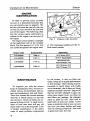
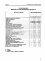
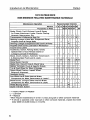
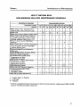
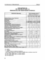
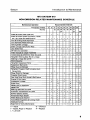

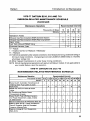

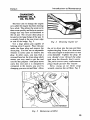
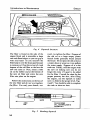


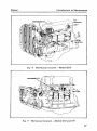
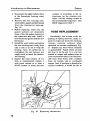

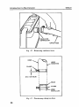
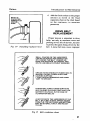
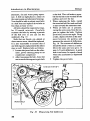


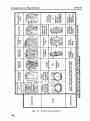
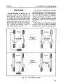

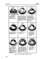
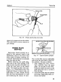
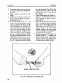
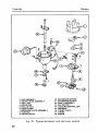


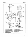
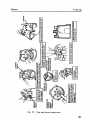


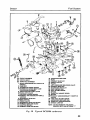
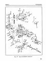
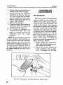
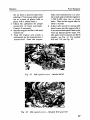
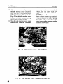


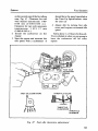
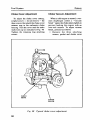
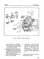
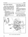
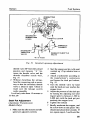
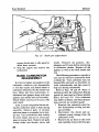
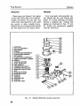
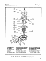
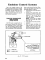

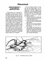


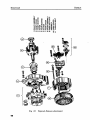
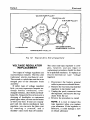
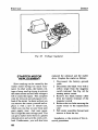
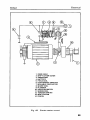
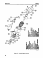


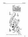
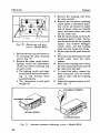
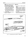
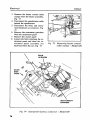
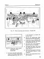
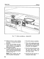
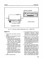


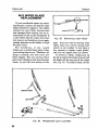


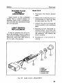

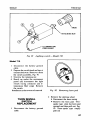
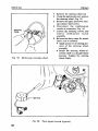
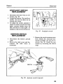


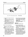
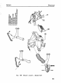
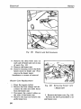
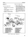

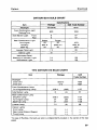
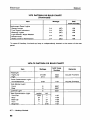


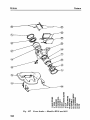

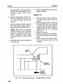

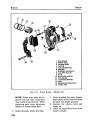
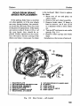
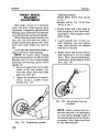
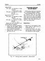
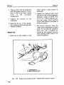
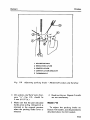
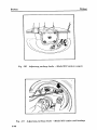

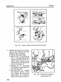


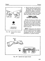
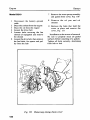
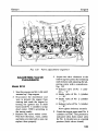
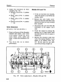
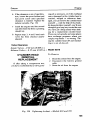
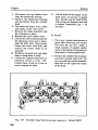

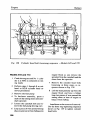
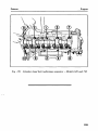
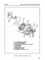

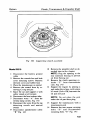

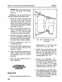
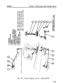
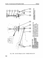
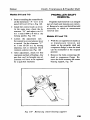
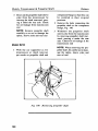


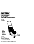
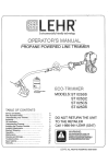
![Manual Audition 4 [By Dr.J.]](http://vs1.manualzilla.com/store/data/005935757_1-4addafd8884e379cc6f9c4cc1fe5fdba-150x150.png)