1
GENERAL
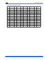
The outdoor units are designed to be connected to a matching indoor coil with sweat connect lines. Sweat connect units
are factory charged with refrigerant for a matching indoor coil
plus 15 feet of field supplied lines.
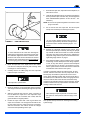
This product must be installed in strict compliance
with the enclosed installation instructions and any
applicable local, stat, and national codes including,
but not limited to, building, electrical and mechanical
codes.
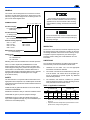
NOMENCLATURE
E
4
FD 030 S 06
Product Category
E = Outdoor Split System
Heat Pump
Product Generation
4 = Design Level
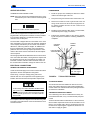
Incorrect installation may create a condition where the
operation of the product could cause personal injury
or property damage.
Product Identifier
FD = 10 SEER Heat Pump (60 Hz)
Nominal Cooling Capacity
018 = 1.5 Tons
042 = 3.5 Tons
024 = 2 Tons
048 = 4 Tons
030 = 2.5 Tons
060 = 5 Tons
036 = 3 Tons
Refrigerant Line Connections
S = Sweat-Fittings
Voltage Code
06 = 208/230-1-60
25 = 208/230-3-60
46 = 460-3-60
Matching indoor coils are available with a thermal expansion
valve or an orifice liquid feed (YORKMATE flow control
device) sized for the most common usage. The orifice size
and/or refrigerant charge may need to be changed for some
indoor-outdoor unit combinations, elevation differences or
total line lengths. Refer to Application Data covering “General
Piping Recommendations and Refrigerant Line Length”
(Form 690.01-AD1V).
INSPECTION
As soon as a unit is received, it should be inspected for possible damage during transit. If damage is evident, the extent of
the damage should be noted on the carrier’s delivery receipt.
A separate request for inspection by the carrier’s agent
should be made in writing. See Local Distributor for more
information.
LIMITATIONS
The unit should be installed in accordance with all national
and local safety codes and the limitations listed below:
1.
Limitations for the indoor unit, coil and appropriate
accessories must also be observed.
2.
The outdoor unit must not be installed with any duct work
in the air stream. The outdoor fan is the propeller type
and is not designed to operate against any additional
external static pressure.
3.
The maximum and minimum conditions for operation
must be observed to assure a system that will give maximum performance with minimum service.
SAFETY
Use this instruction in conjunction with the instruction for the
appropriate indoor evaporator coil, variable speed air handler
or furnace and other accessories. Read all instructions before
installing the unit.
Installer should pay particular attention to the words: NOTE,
CAUTION and WARNING.
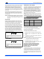
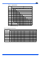
Table 1: Application Limitations
AIR TEMPERATURE °DB ON
OUTDOOR COIL
Min.
NOTES are intended to clarify or make the installation easier.
CAUTIONS are given to prevent equipment damage.
WARNINGS are given to alert the installer that personal
injury and/or equipment damage may result if installation procedures are not handled properly.
2
AIR TEMPERATURE ON
INDOOR COIL
Max.
Min.
Cool
Heat
Cool
Heat
°WB
Cool
50
-10*
115
75
57
Max.
°DB
Heat
°WB
Cool
°DB
Heat
50†
72
80
*.
Below -10°F, the unit operates automatically with resistance
heat only.
†.
Operation below this temperature is permissible for a short
period of time, during morning warm-up.
Unitary Products Group