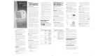
1
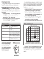
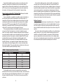
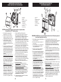
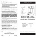
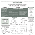
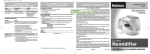
READ AND SAVE THESE
INSTRUCTIONS
OWNER’S MANUAL
FOR BYPASS AND FAN POWERED HUMIDIFIERS
Includes Safety, Operating and Maintenance Instructions
©2005 CAC/BDP
7310 West Morris St., Indianapolis, IN 46231
10006720 11.05
B2203903A
Form/Catalog: OG-HUM-03
Bypass and Fan Powered Humidifiers
Table of Contents
Page
Introduction . . . . . . . . . . . . . . . . . . . . . . . . . . . . . . . . . . . . . . . . . . . . . . . . . . . . 2
Principle of Operation . . . . . . . . . . . . . . . . . . . . . . . . . . . . . . . . . . . . . . . . . . . . 2
Operating Instructions . . . . . . . . . . . . . . . . . . . . . . . . . . . . . . . . . . . . . . . . . . . 4
Effect of Water Characteristics . . . . . . . . . . . . . . . . . . . . . . . . . . . . . . . . . . . 8
Annual Maintenance. . . . . . . . . . . . . . . . . . . . . . . . . . . . . . . . . . . . . . . . . . . . . 8
Annual Summer Shutdown . . . . . . . . . . . . . . . . . . . . . . . . . . . . . . . . . . . . . . . 8
Periodic Preventative Maintenance . . . . . . . . . . . . . . . . . . . . . . . . . . . . . . . 9
Maintenance Instructions
Small and Large Bypass Humidifiers . . . . . . . . . . . . . . . . . . . . . . . . . . . 10
Fan Powered Humidifiers . . . . . . . . . . . . . . . . . . . . . . . . . . . . . . . . . . . . . 11
WARNING! 120 VOLTS may cause injury from electrical shock.
Disconnect power and shut off water supply before servicing.
CAUTION! Sudden operation may cause personal injury or
property damage. Turn humidistat to “OFF” before servicing.
Introduction
Thank you for your recent humidifier purchase. We sincerely appreciate your
business and are pleased to add your name to our growing list of customers.
Now, please take a few minutes and read this booklet. This will familiarize you
with the benefits you will receive from the equipment you just purchased and
help you understand the routine maintenance that will be required.
I. Principle of Operation
You have purchased a humidifier that operates on the evaporative principle.
It will provide the proper relative humidity (see operating instructions) all during
the heating season. It is very possible that you have questions concerning what
your new humidifier can do for you, and what you should do to receive maximum
benefits from it. This booklet is intended to answer these questions.
2
The humidifier operates in conjunction with the furnace blower motor. When
the humidistat calls for humidity and the blower motor is operating, water flows
to the distribution pan located at the top of the unit. The water is uniformly distributed across the width of the pan and through a scientifically designed system
of outlets. It flows by gravity over the humidifier pad. Dry, hot air is moved
through the moisture-laden humidifier pad where evaporation takes place. The
now-humidified air carries moisture in vapor form throughout the home.
The correct water flow is determined by an orifice in each unit. When the
unit is operating, there will be a small, steady stream of water to drain, which
flushes away most of the trouble-causing minerals. Do not use the saddle valve
to regulate the water flow. It is designed to be completely opened or closed.
The minerals and solid residue not trapped by the replaceable humidifier pad
are flushed down the drain. The drain also eliminates the problems caused by
stagnant water. This is the most effective and least expensive method to dispose
of trouble-causing minerals.
Trouble-free performance and minimum maintenance are assured by the
design features of the humidifier. All unit housing parts that come in contact with
water are non-metal and will never rust or corrode. Neither heat nor water will
affect them under normal operating conditions.
The humidifier pad, designed especially for uniform, high evaporation, and
the Scale Control Insert also efficiently trap mineral deposits which are often the
cause of damage to working parts in ordinary humidifiers. No “white dust” can
be distributed throughout the living quarters. The humidifier pad must be in good
condition to assure high capacity trouble-free performance. It should be
changed annually.
Older design water distribution trays have a granular coating in the bottom of
the distribution tray to provide equal distribution of water to each of the openings
assuring an even flow over the humidifier pad. Do not clean the mineral scale off
the bottom of the water distribution tray at the end of the humidification season.
If the granular coating is removed, it is not necessary to purchase a new distribution tray. You can accomplish the same uniform performance by applying a
small amount of liquid dishwashing soap over the entire inside surface of the
water distribution tray. This will allow the water to flow evenly through each of
the openings, provided the unit is level, in order to achieve maximum capacity.
The current distribution tray which incorporates a synthetic fabric liner that
replaces the granular coating, is designed to deliver water uniformly over the
entire top surface of the humidifier pad, provided it is mounted level. It is normal
for some mineral deposits to form in the distribution tray as it dries out between
humidification cycles. These deposits can actually help distribute water in the
tray, but if they form enough to block the openings, they should be removed as
described in the “Periodic Preventative Maintenance” section of this manual.
3
II. Operating Instructions
Your new humidifier is controlled by a manual humidistat, HumidiTrac™
or
Thermidistat™, installed either in the living area or in the cold air return.
Automatic Humidifier Control: (Manual Humidifier Control – see page 6)
Your HumidiTrac™ Control is installed in the cold air return. During the first
heating season, your HumidiTrac™ Control needs to be set initially to match
your home’s condition. Please follow these steps when adjusting your control
(refer to Figure A).
1. Turn the dial setting knob to “5,” which is within the normal range. During
the next 24-48 hours it may be necessary to adjust the dial for more or
less humidity, depending on your personal comfort and home’s
requirements. Refer to “TABLE 1 – Operation Guide”.
2. During the coldest portion of the first heating season, minor adjustments
may be necessary. This is dependent upon your individual home
construction, refer to “TABLE 1 – Operation Guide”.
TABLE 1 – Operation Guide
Condition
Solution
TABLE 2 – % Relative Humidity Guide
Reduce the setting on the control dial
by 1 increment.
Lack of humidity
Increase the setting on the control dial
by 1 increment.
Humidifier does not operate
Turn dial to “Test.” Make certain furnace and
blower are operating. If unit still doesn’t operate,
consult your air conditioning and heating dealer.
Humidifier won’t shut off
Turn dial to “Off.” If unit continues to operate,
consult your air conditioning and heating dealer.
Test mode
System operation is checked by setting the knob to
“Test.” Make certain furnace and blower are
operating. Humidifier will operate for one minute.
Dial Setting
Outdoor Temperature (°F)
Condensation on windows
The relative humidity in your home will
now be accurately controlled to meet
your needs and should not need further
adjustment during future heating
seasons. Make note of the dial setting
in the event you temporarily move the
knob when performing annual
maintenance of the Humidifier.
Your Automatic Humidifier, is a high precision system that will accurately
maintain the relative humidity in your home. For every 1°F change in outdoor
temperature, the control will automatically adjust the indoor relative humidity
(RH) by 1/2%. If you would like to determine the RH in your home, follow
these steps:
1. Determine the outdoor temperature.
2. Activate the furnace blower by setting your thermostat fan switch to the
“On” position, or setting your thermostat to a higher temperature.
3. Turn the control dial setting to the “Off” position. Then, slowly turn the
dial clockwise until you hear the solenoid valve “click on.” Next, slowly
turn the dial counter-clockwise until you hear the solenoid valve “click
off.” At this point, make note of the dial setting.
4. Locate your dial setting on Table 2. Follow the dial setting to the right
until it intersects with the current outdoor temperature. This is the
relative humidity in your home under existing conditions.
5. Return the thermostat and the Humidifier Control to their original settings.
-10
0
10
20
30
40
1
10
10
10
15
20
25
2
10
10
15
20
25
30
3
10
15
20
25
30
35
4
15
20
25
30
35
40
5
20
25
30
35
40
45
6
25
30
35
40
45
45
7
30
35
40
45
45
45
As an example, if the outdoor temperature is 20°F, and, following step 3,
the humidifier turns off at “5” on the dial range, then the RH in your home is 35%.
FIGURE A
The HumidiTrac™ Control will accurately control the humidity in your home
to a maximum of 45% RH and a minimum of 10% RH. The values of outdoor
temperature and dial settings may fall in between or outside of the listed
values in Table 2. In these cases, you can only approximate your home’s actual
indoor RH.
90-1054
4
5
To check the humidifier’s operation, note the current setting and set the
HumidiTrac™ Control to the test mode when the furnace blower motor is
operating. Water will flow into the humidifier for 1 minute and then it will turn
off. This insures the unit is operating properly. Do not leave the control in the
test mode as it will not operate. Reset the control to it’s original setting.
Manual Humidistat or HumidiTrac™ in Manual Mode: (Automatic Humidifier
Control – see page 4)
Your new Humidifier is controlled by a humidifier control installed either in
the living area (typically near the thermostat) or in the cold air return. It is
important to anticipate a drop in outdoor temperature and reduce the setting
accordingly to avoid excessive condensation. For example, with an outdoor
temperature of 20°F the correct setting will be 35% relative humidity. If the
temperature is expected to fall to 0°F that evening, then merely reduce the
setting to 25% several hours prior to the temperature change.
The recommended settings on the humidifier control are based on years of
research (see Table 3) and experience as to what is best for the average
home. These settings represent a compromise between RH levels that would
be most desirable for comfort reasons and humidity levels that are suitable for
protection of your home. For example, a wintertime indoor RH of 50% may be
considered ideal by some, but unfortunately, it probably would result in
damage to your home. Observance of the recommended RH levels on your
humidistat, therefore, is an important safeguard. Condensation of water on
inside windows in the form of fogging or frost is usually an indication of too
high relative humidities. This same condensation can take place in other areas
in your home with the possibility of damage resulting.
To check the humidifier operation, set the humidifier control above the
click point, make sure that the water saddle valve is open and that there is
electricity to the unit. Generally, the furnace and blower motor must be operating for the humidifier control to function. After the humidifier has operated for
several minutes and water is entering the unit and coming out at the drain,
reduce the humidifier control setting below the click point and the unit should
automatically shut off. Now set the humidistat dial at the recommended inside
relative humidity, depending on the outside temperature. Follow the suggested
settings prior to a drop in the outside temperature.
Additional Information
Be sure to keep fireplace dampers closed when not in use. They provide
an excellent escape route for heat, as well as humidity. Humidity is lost at an
even faster rate than heat because water vapor tends to seek its own level
and your humidifier would not be able to replace it even when running at full
capacity.
On occasion, indoor moisture producing activities such as clothes drying,
cooking, showers, etc., may raise the relative humidity level higher than it
should be, even though the Humidifier is not operating. Telltale indications,
again, are condensation or frost on cold surfaces such as windows, doors,
walls, etc. If such condensation persists for several hours, your home should
be ventilated to dissipate the potentially damaging excess moisture.
TABLE 3 – Outdoor-Indoor Relative Humidity
Outside Temperature
Recommended RH
+40°F
+30°F
+20°F
+10°F
0°F
–10°F
–20°F
45%
40%
35%
30%
25%
20%
15%
The Humidifier Control is a precision instrument that can be used to
determine the RH accurately in your home during the winter. Turn the dial to the
lower setting, then reverse the dial direction slowly until a “click” is heard. At
this point, read the RH on the dial. This will be very close to the actual RH in
your home.
6
7
III. Effect of Water Characteristics
VI. Periodic Preventative Maintenance
Your humidifier will operate effectively using either hard or mechanically
softened water.
Any type of water (hard, soft, hot, or cold) is acceptable for use with the
drain-type humidifiers. Hot supply water, 140° maximum, is recommended for
all heat pump applications. The use of hot supply water will also increase the
amount of humidity generated in other applications. The heat in the water
increases evaporation and the water going to the drain is cold to the touch. For
better performance it is recommended that soft (reduced minerals) or filtered
water be supplied to the humidifier pad. This can help reduce the amount of
scale and mineral deposits that can accumulate on the pad.
NOTE: Periodic inspection and preventative maintenance of your total heating system is important for efficient and safe operation. Your dealer will include
humidifier service during a maintenance inspection.
Your humidifier is equipped with an in-line water strainer and orifice as
shown below. These parts should be inspected and cleaned periodically to
assure continued proper unit performance.
IV. Annual Maintenance
For best performance, we recommend that you replace the humidifer pad
in your humidifier annually.
• Call the installer of your humidifier. This information is often found on your
equipment.
V. Annual Summer Shutdown
FOR THE SUMMER HUMIDIFIER SHUTDOWN, SIMPLY TURN THE
HUMIDISTAT CONTROL TO THE “OFF” SETTING AND CLOSE THE DAMPER IN
THE BYPASS HUMIDIFIER. (TURN DAMPER HANDLE TO “SUMMER” POSITION)
8
Inspection and Service Instructions
1. Disconnect electrical power to the furnace and shut off
water supply.
2. Disconnect the water line at the inlet fitting.
3. Remove the in-line strainer from inside the inlet fitting by
ORIFICE
using a small nail or wire.
4. Flush the in-line strainer to clean it. If it is necessary
SOLENOID
to replace the strainer, contact your dealer for a
VALVE
replacement.
INLET
5. Disconnect the water line at the outlet fitting.
6. Inspect plastic feed tube by gently flexing it and looking
IN-LINE
for cracks or signs of wear. Replace tube if it is cracked,
STRAINER
brittle, or has been damaged.
7. Remove the orifice from the copper or plastic tube and
INLET
make sure this small opening is unplugged.
COMPRESSION
NUT
8. Replace the orifice and reconnect the outlet water line
90-1053
(Double Wrench To Prevent Leaking And Valve Damage).
9. Replace the inline strainer and reconnect the inlet water line (Double Wrench To
Prevent Leaking And Valve Damage).
10. Inspect the drain hose to make sure it has a constant downward slope and is
not flattened or blocked. Flex the hose to loosen any mineral deposits or
blockage. Flush it with water under pressure to remove any debris.
11. Turn on water supply and reconnect electrical power to the furnace.
OUTLET
COMPRESSION
NUT
9
MAINTENANCE INSTRUCTIONS FOR
FAN POWERED HUMIDIFIER
MAINTENANCE INSTRUCTIONS FOR
SMALL AND LARGE BYPASS HUMIDIFIERS
3
4
5
2
7
1
1. Front Cover
2. Feed Tube
3. Nozzle
4. Evaporative Assembly
5. Distribution Tray
6. “V” Notches
7. Humidifier Pad
8. Scale Control Insert
9. Drain Hose
10. Bypass Damper
90-819
1.
2.
3.
4.
5.
6.
7.
8.
9.
6
Front Cover
Base
Evaporative Assembly
Distribution Tray
”V” Notches
Humidifier Pad
Scale Control Insert
Drain Hose
Power Cord
8
CAUTION! Sudden operation may cause personal injury or property damage.
Turn humidistat to “OFF” before servicing.
1.
2.
3.
4.
Note humidistat setting and turn
humidistat to the “OFF” position.
At the side of the unit opposite the
airflow duct, pull front cover (1) off
holding with both hands and set aside.
Carefully pull the feed tube (2) out of
the nozzle (3) at the top of the
evaporative assembly (4). Pull this
assembly out by grasping at top and
tipping out.
Remove the black distribution tray (5)
from the evaporative assembly by
unsnapping the white plastic ends of
the Scale Control Insert (8), from the
tabs at the end of the tray. Follow the
instructions below depending upon
the type of distribution tray in your
humidifier:
For trays with a synthetic fabric liner:
Lightly scrape out or brush off any
mineral deposits, being careful not to
stretch or loosen the synthetic fabric
liner. Soaking the tray in vinegar or a
lime-removing agent is helpful when
trying to remove stubborn mineral
deposits.
For trays with granular coating: Do not
scrape off the granular coating, but
lightly scrape out any mineral deposits
and clean the “V” notches (6). This
textured surface helps ensure even
water flow for maximum performance.
If the granular coating has been
removed, place several drops of liquid
dishwashing soap on the distribution
tray. This will only need to be done
once if there is no granular coating.
Slide the humidifier pad (7) out from the
plastic Scale Control Insert (8). Clean the insert
frame by twisting and flexing it to loosen the
calcium deposits, or use a putty knife. Replace the
humidifier pad (Part No. P110-1045 for Small
Bypass Humidifier and Part No. P110-3545 for Large
Bypass Humidifier) and slide the pad back into the
scale control insert frame with color mark up. Snap
the black distribution tray (5) back into place.
6. Inspect plastic feed tube by gently flexing it and
looking for cracks or signs of wear. Replace tube if
it is cracked, brittle, or has been damaged.
7. Reinstall the evaporative assembly into the unit by
fitting its drain tube into the round receptacle at the
base of the unit. Push the assembly in at the top
against the beveled tabs that will hold it in place.
Push the end of the feed tube back firmly into the
nozzle and replace the front cover.
8. Remove the drain hose (9) from the bottom of the
unit and bend and flex it to loosen the internal
calcium deposits. Then flush it with water under
pressure and slip it back onto the black drain fitting.
Make sure the drain hose has a constant
downward slope and is not flattened or blocked.
9. Check system operation:
Manual Humidistat: With the furnace blower
operating and the furnace calling for heat, turn up
Humidistat and check system operation.
HumidiTrac™ Humidifier Control: (Automatic or
Manual) Check system operation and reset Change
Humidifier Pad indicator by setting the knob to
“Test/Reset”. With furnace blower operating and
furnace calling for heat, humidifier will operate for
one minute. DO NOT LEAVE IN TEST MODE AS
HUMIDIFIER WILL NOT OPERATE.
10. Set Manual Humidistat or HumidiTrac™ Humidifier
Control to its original position.
90-858
5.
10
9
WARNING! 120 VOLTS may cause serious injury from electrical shock. Disconnect power and
shut off water supply before servicing.
1. Note humidistat setting and turn humidistat
to the “OFF” position.
2. Disconnect electrical power and turn off
water supply.
3. Unlatch humidifier cover assembly (1) from
base assembly (2) at the bottom of the
cover, lift, and set aside.
4. Pull out the evaporative assembly (3) by
grasping at the top and tipping out.
5. Remove the black distribution tray (4) from
the evaporative assembly by unsnapping
the white plastic ends of the Scale Control
Insert (7), from the tabs at the end of the
tray. Follow the instructions below
depending upon the type of distribution tray
in your humidifier:
For trays with a synthetic fabric liner:
Lightly scrape out or brush off any mineral
deposits, being careful not to stretch or
loosen the synthetic fabric liner. Soaking
the tray in vinegar or a lime-removing
agent is helpful when trying to remove
stubborn mineral deposits.
For trays with granular coating: Do not
scrape off the granular coating, but lightly
scrape out any mineral deposits and clean
the “V” notches (5). This textured surface
helps ensure even water flow for maximum
performance. If the granular coating has
been removed, place several drops of
liquid dishwashing soap on the distribution
tray. This will only need to be done once if
there is no granular coating.
6. Slide the humidifier pad (6) out from the plastic
Scale Control Insert (7). Clean the insert frame by twisting
and flexing it to loosen the calcium deposits or use a
putty knife. Replace the humidifier pad (Part No.
P110-3545) back into the Scale Control Insert with the
colored spot up and snap the black distribution tray (4)
back into place.
7. Reinstall the evaporative assembly (3) into the base
assembly (2). Push the evaporative assembly (3) in at the
top between the retaining ribs that hold the assembly in
place in a vertical position.
8. Remove the drain hose (8) from the bottom of the unit.
Bend and flex it to loosen the internal calcium deposits.
Then flush it with water under pressure and slip it back
onto the drain fitting. Make sure the drain hose has a
constant downward slope and is not flattened or blocked.
9. Reinstall cover assembly (1) by hooking at the top of base
assembly (2) and latching at the bottom.
10. Reconnect electrical power (9) and turn on water supply.
11. Check system operation:
Manual Humidistat: With the furnace blower operating
and the furnace calling for heat, turn up Humidistat and
check system operation.
HumidiTrac™ Humidifier Control: (Automatic or Manual)
Check system operation and reset Change Humidifier
Pad indicator by setting the knob to “Test/Reset”. With
furnace blower operating and furnace calling for heat,
humidifier will operate for one minute. DO NOT LEAVE IN
TEST MODE AS HUMIDIFIER WILL NOT OPERATE.
12. Set Manual Humidistat or HumidiTrac™ Humidifier
Control to its original position.
11