1
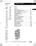
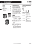
NEMA Contactors & Starters
Freedom
33-87
March 2009
Accessories
Auxiliary Contact Location
NEMA Sizes 00 – 2, IEC Sizes A – K
NEMA Sizes 3 – 8, IEC Sizes L – Z
The sketches below illustrate the maximum number of auxiliary contacts that can be assembled to a contactor or starter
and their locations.
The sketches below illustrate the maximum number of auxiliary contacts that can be assembled to a contactor and their
locations.
Table 33-138. Auxiliary Contacts
Note: A Base Auxiliary Contact must be added in position R1 before
additional auxiliary contacts can be mounted on NEMA Size 3 and
IEC Sizes L – N, or in L1 on NEMA Sizes 4 – 5 and IEC Sizes P – S.
Catalog
Number
Size
AE16
A–K
AN16
Poles
Available Mounting Positions Open Type
Enclosed
3
T1, L1
L1
00
0–2
3
3
T1, L1, R1
T1, L1
L1
L1
AE56
A–K
3
L1, R1
L1, R1
AN56
00 – 2
3
T1, T2
—
CE15
A–C
D–K
G–J
G–J
2–4
3
4
5
T1, L1, R1
T1, L1
T1, R1
T1
L1, R1
L1
—
—
CN15
00
0–2
1, 2
1, 2
2–4
2–3
4
5
T1, L1, R1
T1, L1
T1, L1
T1, L1
L1
L1
—
—
CN35
10A
20 – 60A
60A
60A
2–4
2–3
4
5
T1, L1, R1
T1, L1
T1, L1
T1, L1
L1
L1
—
—
CE55
A–K
3
L1, R1
L1, R1
CN55
00 – 2
3
T1, T2
—
Size
Available Mounting Positions NEMA Size 3, IEC Sizes L – N
R2, R3, L1, L2, L3
NEMA Sizes 4 – 5, IEC Sizes P – S
L2, L3, R1, R2, R3
NEMA Sizes 6 – 7, IEC Sizes T – X
R1
NEMA Size 8, IEC Size Z
L2, R2
Available positions on contactors or starters other than what is factory
installed.
Rear
L1
L2
L3
R3
Base Aux. Aux.
Aux. Cont. Cont.
Cont.
Front
of Contactor
Left Side
of Contactor
L1
Right Side
of Contactor
NEMA Sizes 3 – 5
IEC Sizes L – S
L1
R1
R1
R1
NEMA Sizes 6 – 7
IEC Sizes T, U, V, W and X
T1
T1
L1
T1
T2
Top View
Top View
R1
L1
T1
T2
L1
R1
L2
R2
R1
NEMA Size 8
IEC Size Z
Front View
Front View
Non-reversing
Contactors and Starters
Reversing
Contactors and Starters
Figure 33-31. Auxiliary Contact Location
Figure 33-30. Auxiliary Contact Location
CA08102001E
For more information visit: www.eaton.com
R1
Aux. Aux. Base
Cont. Cont. Aux.
Cont.
Available positions on contactors or starters other than what is factory
installed.
When a pneumatic timer is mounted on contactor, only side mounted
auxiliary contact positions are available. The solid-state timer, when
added, takes up side mounted auxiliary contact position.
L1
R2
Rear
Table 33-139. Mounting Positions
33