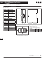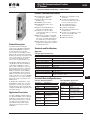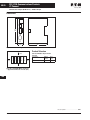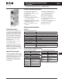
1
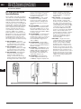
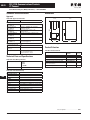
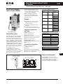
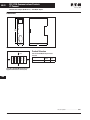
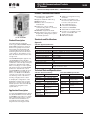
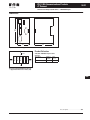
PLC, I/O & Communications Products
50-1
PLC, I/O & Communications
Products
February 2009
Contents
Description
Page
ELC Programmable Logic Controllers
ELC Product Family Overview . . . . . . . . . . . . . . . . . . . . . . . . . . . . . . . . . .
ELC Controller Features . . . . . . . . . . . . . . . . . . . . . . . . . . . . . . . . . . . . .
ELC Right Side Digital Expansion Modules . . . . . . . . . . . . . . . . . . . . .
ELC Right Side Analog and Specialty Module . . . . . . . . . . . . . . . . . . .
ELC Left Side Speciality Modules . . . . . . . . . . . . . . . . . . . . . . . . . . . . .
ELC Power Supplies . . . . . . . . . . . . . . . . . . . . . . . . . . . . . . . . . . . . . . . .
ELC Accessories . . . . . . . . . . . . . . . . . . . . . . . . . . . . . . . . . . . . . . . . . . .
ELC Programming Software. . . . . . . . . . . . . . . . . . . . . . . . . . . . . . . . . .
Product Selection . . . . . . . . . . . . . . . . . . . . . . . . . . . . . . . . . . . . . . . . . . . .
Specifications . . . . . . . . . . . . . . . . . . . . . . . . . . . . . . . . . . . . . . . . . . . . . . . .
Dimensions . . . . . . . . . . . . . . . . . . . . . . . . . . . . . . . . . . . . . . . . . . . . . . . . .
IT. Connect
Starter Network Adapters (SNAP) (D77B Series) . . . . . . . . . . . . . . . . . . .
DeviceNet SNAP . . . . . . . . . . . . . . . . . . . . . . . . . . . . . . . . . . . . . . . . . . .
QCPort SNAP . . . . . . . . . . . . . . . . . . . . . . . . . . . . . . . . . . . . . . . . . . . . . .
Communication Adapters (D77D Series) . . . . . . . . . . . . . . . . . . . . . . . . . .
DeviceNet Adapter . . . . . . . . . . . . . . . . . . . . . . . . . . . . . . . . . . . . . . . . .
Modbus Adapter . . . . . . . . . . . . . . . . . . . . . . . . . . . . . . . . . . . . . . . . . . .
EtherNet/IP Adapter . . . . . . . . . . . . . . . . . . . . . . . . . . . . . . . . . . . . . . . .
PROFIBUS Adapter . . . . . . . . . . . . . . . . . . . . . . . . . . . . . . . . . . . . . . . . .
Accessories (D77E Series) . . . . . . . . . . . . . . . . . . . . . . . . . . . . . . . . . . .
CH Studio Component Manager Software . . . . . . . . . . . . . . . . . . . . . . . .
50-19
50-19
50-21
50-23
50-23
50-25
50-27
50-29
50-30
50-32
50
ELC and IT. Products
CA08102001E
50-2
50-3
50-5
50-6
50-8
50-9
50-9
50-10
50-11
50-12
50-13
For more information visit: www.eaton.com
PLC, I/O & Communications Products
ELC Programmable Logic Controllers
50-2
February 2009
ELC Controllers / Modules
ELC Product Family Overview
ELC Controller and Expansion Modules
The Eaton Logic Controller (ELC) is
Eaton’s latest offering into the PLC
(Programmable Logic Controller)
marketplace. This small sized device,
with its abundant module selection,
provides all of the big PLC features
you need at a micro PLC price.
■
■
■
50
■
■
Size – Large PLC features with controllers as small as 1-inch in width.
Half the size of competitive offerings. ELC can fit more I/O in the
same space and allow cost savings
by reducing cabinet size.
Flexibility – ELC controllers expand
to over 500 points of I/O on the PV
models and over 230 on all other
models.
❑ Add only the amount of I/O you
need. Choose I/O counts as
small as 2 points and as large
as 16 points per module.
❑ DIN-rail mounting lets you add
as many modules as needed
by snapping them into mating
connectors.
Large PLC Features – Multiple
communications ports, distributed
I/O capability, high-speed counters,
high-speed pulse outputs, interrupts, timer resolution to 1ms,
PIDs, plus much more.
Software – ELCSoft programs in
standard ladder or sequential
function chart programming.
❑ Display registers “in use” and
modules attached to the ELC.
❑ Monitor runtime applications.
Force (except PB model), and
enter/modify register values.
❑ Wizards aid programming of ELC
Link for distributed I/O, standard
communications, high-speed
counters, pulse outputs, positioning, interrupts, PIDs and extension module setup.
Communications – Connecting to
networks is easy on Modbus,
Modbus TCP, DeviceNet™, and
PROFIBUS.
Using these technologies, the ELC
can connect to communicating
MCCs where the ELC is a master on
DeviceNet or Modbus TCP. ELC also
communicates to PowerNet products
over Modbus and Modbus TCP, providing connectivity to switchgear and
PowerNet applications.
Of course, the ELC communicates
seamlessly to Eaton’s operator
interface products.
ELC Controllers/Modules
Product Description
ELC Controllers
The ELC family offers five styles of
controllers. These controllers offer
combinations of the following features:
■
■
■
■
■
■
■
■
High-speed pulse capture and
high-speed pulse output, up to
200 kHz.
Up to 22 interrupts.
Large selection of discrete I/O
modules including AC/DC in,
relay/transistor out, and high
current relay out.
Large selection of specialty modules
including analog in, out, combined,
thermocouple, RTD Platinum.
Over 200 instructions to choose
from: Floating point math, communications, 16- and 32-bit math,
logical, block move, block compare,
retentive data storage, conversion,
time base from clock/calendar.
2 Modbus (ASCII or RTU) serial
ports: 1 slave only, 1 master/slave.
Network communications on
Modbus TCP, DeviceNet and
PROFIBUS.
ELC controller can be wired for
remote I/O communications
(except the PB model).
For more information visit: www.eaton.com
ELC Modules
ELC Expansion Modules
ELC expansion modules provide the
correct amount of I/O for application
solutions. Choose from a wide selection of 4, 6, 8 and 16 point I/O modules
to create a system with up to 508
points of I/O (256 inputs and 252
outputs maximum).
ELC Specialty Modules
In addition to discrete expansion I/O,
specialty modules like Analog In,
Analog Out, Platinum Temperature,
Thermocouple and Switch Modules
are available.
The RS-485 adapter can easily connect
an MVX9000 drive to a network of
ELCs on Modbus. DeviceNet and
PROFIBUS DP slave modules are
available for right side mounting to
all controllers, while Ethernet and
DeviceNet scanner specialty modules
can be added to the left side of the
ELC-PV controllers.
CA08102001E
PLC, I/O & Communications Products
ELC Programmable Logic Controllers
50-3
February 2009
ELC Controllers / Modules
Catalog Number Selection
Table 50-1. ELC Controllers/Modules Catalog Numbering System
E L C - PA
10 A A D R
Device Type
PB = Processor without clock
PC = Processor with clock
PH = Processor with clock and
high-speed I/O
PA = Processor with clock and
embedded analog
PV = Processor with clock, high-speed
I/O and high-speed CPU
AN = Analog Expansion Module
EX = Digital Expansion Module
PT = Platinum RTD Expansion Module
TC = Thermocouple Expansion Module
ELC Controller Features
There are 5 controller styles:
■
PB Series (Basic) – 14 I/O (8i/6o).
Over 130 instructions provide all the
power you need. Add expansion
modules to the right side of the unit
to create applications with up to 230
I/O points. Two Modbus (ASCII/RTU)
serial ports for master/slave communications. The master port is
RS-485 with the ability to communicate to 31 other devices. The master
port can also be configured to communicate to devices such as ASCII,
bar code readers, etc. The program
is stored in EEPROM for retention in
the event of power loss. This unit
does not provide a real-time clock.
■ PC Series (Clock/Calendar) – 12 I/O
(8i/4o). Same features as the basic
model plus clock/calendar, distributed I/O capability with up to 16
devices, and file area for data storage and retrieval. The program is
stored in RAM with battery backup.
The replaceable battery has greater
than a 5-year life. This unit also has
2 digital potentiometers that vary
the data in internal registers.
CA08102001E
Digital Outputs
I/O Count
xx = Total Number
of I/O
Analog Outputs
A = Analog
N = None
Analog Inputs
Digital Inputs
A
D
S
N
= AC
= DC
= Switch
= None
T
R
I
N
= Transistor
= Relay
= High Current Relay
= None
A = Analog
N = None
■
PA Series (Analog) – 10 I/O (6i/4o).
Same features as PC Series with a
different I/O mix. This unit has a
total I/O mix of 4 digital inputs,
2 digital outputs, 2 analog inputs,
and 2 analog outputs. The analog
channels can be set up for either
voltage or current. This unit has
(2) 7-segment LEDs that can be
used to display unit ID, error codes,
process steps, etc.
■ PH Series (High-Speed) – 12 I/O
(8i/4o). All the features of the PC
Series with the added ability to
capture or output pulses up to 100
kHz and includes single-axis motion
control.
■ PV Series (Advanced) – 28 I/O
(16i/12o). The PV Series has the
most extensive feature set of the
ELC controllers. It allows for expansion up to 508 I/O points and is
compatible with the same expansion modules, specialty modules
and software. Programs written
for the other controllers can be
migrated to a PV controller where
greater speed or more I/O is
required. Compared to the current
ELC controllers, the PV series
provides 10 times improvement
in speed for about 0.24µ seconds/
step. The program is stored in RAM
and backed using a rechargeable
lithium-ion battery. No need to
change batteries. Controller also
includes 2-axis motion control.
For more information visit: www.eaton.com
The new PV series controller adds an
additional expansion bus to the left of
the controller. While the PV series is
compatible with today’s current
expansion modules, which extend to
the right of the controller, you can
add high-speed and specialty modules
to the left. Left side Ethernet master
and DeviceNet master modules are
available for use with the PV Series
controller.
50
PLC, I/O & Communications Products
ELC Programmable Logic Controllers
50-4
February 2009
ELC Controllers / Modules
Specifications
ELC Controllers
PB
Controller
PC and PH
Controllers
PA
Controller
PV
Controller
Figure 50-1. ELC Controllers
Table 50-2. ELC Controller Features and Specifications
Controller
ELC-PB14NNDR/DT
Dimensions W x H x D (mm)
25.2 x 90 x 60
I/O Type — Embedded
14 (8DI/6DO)
ELC-PA10AADR/DT
ELC-PC12NNAR/DR/DT ELC-PH12NNDT ELC-PV28NNDR/DT
37.4 x 90 x 60
10 (4DI/2DO/2AI/2AO)
Maximum Additional I/O Points
28 (16DI/12DO)
224 (112 In/112 Out)
DC In Sink/Source
480 (240 In/240 Out)
Yes
Execution Speed
Basic Instructions — 2 µs Minimum
Program Language
0.24 µs Minimum
Instructions + Ladder Logic + Sequential Function Chart
Program Capacity (steps)
3792
Data Memory Capacity (bits)
1280
Data Memory Capacity (words)
744
5000
2
8
16
None
1600 Words
10,000 Words
32/107
32/168
Index Registers
File Memory Capacity (words)
7920
Commands Basic/Advanced
15,872
4096
Retentive Storage
10,000
Yes
Floating Point
32/193
Yes
SFC Commands (steps)
128
1024
Timers Qty.
128
244 Standard With Additional Timers for Subroutine and Retentive Applications
Timers Resolution
Counters Qty.
50
70 x 90 x 60
12 (8DI/4DO)
High-speed Counters (see note)
Max. High-speed Counting (see note)
Pulse Output
1–100ms
128
250
Up to 4
2 at 20 kHz
1 at 30 kHz
1 at 100 kHz
2 at 200 kHz
2 Channels, 50 kHz Max.
100 kHz
200 kHz
Yes
Master Control Loop
8 Loops
64 Subroutines
256 Subroutines
For/Next Loops
Interrupts
Real-time Clock/Calendar
Up to 8
2 Channels, 10 kHz Max.
PID
Subroutines
Yes
6
15
No
22
Built-in
Password Security
Yes
Diagnostic Relays
Yes
Diagnostic Word Registers
Yes
Specialty Expansion Modules
8 (Analog In/Analog Out/TC/RTD/PT) Modules Do Not Count in Total I/O
Serial Ports
2 Modbus (ASCII/RTU) 1=Slave (RS-232)/11=Master-Slave (RS-485)
Remote I/O
No
Run Time Editing
No
With 16 Other Devices
With 32 Other Devices
Yes
Run/Stop Switch
Yes
Removable Terminal Strips
Special Features
253
Up to 6
Yes
—
2, 7-Segment Displays
2 Potentiometers
2 Potentiometers Highspeed, Left Side Bus
Note: High-speed counter inputs can be used for different types of 32-bit counting, such as single-ended, single-phase two input and quadrature.
Therefore, all high-speed counters may not be used at the same time. Please refer to the ELC Systems Manual, MN05003003E, for details.
For more information visit: www.eaton.com
CA08102001E
PLC, I/O & Communications Products
ELC Programmable Logic Controllers
50-5
February 2009
ELC Controllers / Modules
ELC Right Side Digital
Expansion Modules
Digital right side expansion modules
can be used with any ELC controller.
They simply snap together to allow the
ELC backplane to pass through each
connected module. Add only the
amount of I/O you need. Choose I/O
counts as small as 6 points and as
large as 16 points per module.
I/O modules are available in a broad
selection of AC/DC inputs, relay/transistor and high current outputs which may
be used together in any combination.
outputs can be added to the PV controller. These I/O counts are all independent of the analog and specialty
module I/O counts.
Add as many modules as needed to
reach the proper I/O count. In addition
to the embedded I/O on the PB, PC, PA
and PH controllers, 112 digital inputs
and 112 digital outputs can be added
by use of expansion modules. An additional 240 digital inputs and 240 digital
Style 1
Style 2
Figure 50-2. ELC Right Side Digital Expansion Modules
Table 50-3. ELC Right Side Digital Expansion Module Features
Model
Style
Inputs
Outputs
Points
Type
Points
Type
—
ELC-EX08NNAN — AC IN
1
8
120V AC
0
ELC-EX08NNDN — DC IN
1
8
DC Sink or Source
0
—
ELC-EX08NNNR — Relay OUT
1
0
—
8
Relay
ELC-EX08NNNT — PNP Transistor OUT
1
0
—
8
PNP Transistor
ELC-EX06NNNI — High Current Relay OUT
2
0
—
6
Relay (6 Amps)
ELC-EX08NNDR — IN/OUT Combo
2
4
DC Sink or Source
4
Relay
ELC-EX16NNDR — IN/OUT Combo
2
8
DC Sink or Source
8
ELC-EX08NNDT — IN/OUT Combo
2
4
DC Sink or Source
4
ELC-EX16NNDT — IN/OUT Combo
2
8
DC Sink or Source
8
CA08102001E
For more information visit: www.eaton.com
PNP Transistor
50
PLC, I/O & Communications Products
ELC Programmable Logic Controllers
50-6
February 2009
ELC Controllers / Modules
ELC Right Side Analog and
Specialty Modules
These modules offer various features
other than the standard digital inputs
and outputs. A maximum of 8 analog
and specialty I/O modules can be used
with any controller. The RS-485 connection device can be used separately
from the ELC controllers. All analog,
temperature, and the motion modules
have a separate power input which
must be powered even when connected directly to the ELC controller
system. In addition to a separate
power input, these modules have an
RS-485 port so they can communicate
Modbus to any other Modbus device,
including the ELC controllers. This
allows them to be mounted closer to
the sensing devices for better accuracy.
■
ELC-AN02NANN – 2 channel
analog output module uses voltage
or current mode for any channel
with12 bit resolution in any mode.
■ ELC-AN04NANN – 4 channel
analog output module uses voltage
or current mode for any channel
with12 bit resolution in any mode.
■ ELC-AN06AANN – 4 analog input
channels and 2 analog output
channels. Input channels use
voltage or current mode for any
channel. Inputs are 12 bit resolution
in voltage mode and 11 bits resolu-
■
■
■
■
■
■
tion in current mode. Analog output
channels use voltage or current
mode for any channel with12 bit
resolution in any mode.
ELC-AN04ANNN – 4 analog input
module uses voltage or current
mode for any channel. Inputs are
14 bit resolution in voltage mode
and 13 bits resolution in current
mode.
ELC-PT04ANNN – 4 channel PT100
temperature sensor input module.
Use 3-wire PT100 sensors on each
channel with 14 bit resolution. Temperature ranges from -200 °C~600 °C
or -328 °F~1112 °F.
ELC-TC04ANNN – 4 channel thermocouple temperature sensor input
module. Use J, K, R, S, or T sensors
on any channel with 14 bit resolution. Temperature ranges from
-148 °C~3092°F.
ELC-EX08NNSN – 8 input switch
module. Use for debugging applications or for manual switch inputs to
the ELC controller.
ELC-COPBDP – PROFIBUS-DP slave
module. Supports baud rates up to
12M bps with auto-baud detection.
Consumes 4 bytes of input data
(32 input bits of X) and 4 bytes or
output data (32 bits of Y).
ELC-CODNET – DeviceNet slave
module. Supports baud rates up
to 500K bps. Supports explicit and
polled connections. Consumes
4 bytes of input data (32 input bits
of X) and 4 bytes or output data
(32 bits of Y).
■ ELC-485APTR – Used primarily for
easy connection of an MVX/NFX
drive to the ELC controller. This
module is a passive RS-485 connection device. It has an RJ12 port for
connecting to a drive. It has a 2-pin
screw terminal to connect to the ELC
controller. It also has 1 male DB9
and a female DB9, which may be
used for connecting to other RS-485
devices. This module can be connected directly to the ELC controller
but should be placed as the last
module to the right since it does
not pass the I/O bus through to
the next module.
■ ELC-MC01 – Single axis motion
control module. Can be used with
any ELC controller for single axis
motion control. Add more MC01
modules for up to 8 axes. If used
with the PH series controller it can
provide a second axis since the PH
series has single axis built in. If used
with the PV series controller it can
perform as a 3rd axis motion control
module since the PV series incorporates 2 axis of motion control and is
capable of providing output pulses
up to 200 kHz.
50
Figure 50-3. RS-485 Network
For more information visit: www.eaton.com
CA08102001E
PLC, I/O & Communications Products
ELC Programmable Logic Controllers
50-7
February 2009
ELC Controllers / Modules
DOG
COM1
3
3
2
0
x10
LSP
LSN
A
B
PG0
ELC-MC01
CLR
COM2
ELC-EX485APTR
ON
1 2 3 4
DR1
DR0
IN1
IN0
ELC-CODNET
ELC-COPBDP
STOP
1
x10
6
DIP
1
6
5
0
5
s
START
9
x160
X7
4
6
2
1
4
X6
3
5
8
NODE ADDRESS
x161
s
L.V
4
7
X5
POWER
ERROR
8
X4
ELC-EX08NNSN
MS
7
X2
X3
2
POWER
NET
NS
X1
1
POWER
0
IN
X0
9
ON
0
FP
RP
7
Style 1
Style 2
Style 3
Style 4
Style 5
Style 6 — with
ELC-ACCOVER
Style 7
Figure 50-4. ELC Right Side Analog and Specialty Modules
Table 50-4. ELC Right Side Analog and Specialty Module Features
Model
ELC-AN02NANN — Analog OUT
ELC-AN04NANN — Analog OUT
ELC-AN06AANN — Analog Combo
ELC-AN04ANNN — Analog IN
ELC-PT04ANNN — PT100
ELC-TC04ANNN — Thermocouple
ELC-EX08NNSN — Switch Input
ELC-COPBDP — PROFIBUS DP (Slave)
ELC-CODNET — DeviceNet (Slave)
ELC-485APTR — RS-485 Easy Connect
ELC-MC01 — Single Axis Motion Control
Power
24V DC
24V DC
24V DC
24V DC
N/A
24V DC
Style
1
2
2
2
2
2
3
4
5
6
7
Inputs
Points
0
0
4 (V = 12 bits, I = 11 bits)
4 (V = 12 bits, I = 13 bits)
4 (V = 14 bits, I = 14 bits)
4
8
32
32
0
N/A
Type
—
±10V, ±20 mA
±10V, ±20 mA
PT100
Thermocouple
Switch
Digital
Digital
—
Phase in, Start,
Stop, etc.
Outputs
Points
2 (12 bits)
4 (12 bits)
2 (12 bits)
0
0
0
0
32
32
0
N/A
Type
0~20 mA, 4~20 mA
0V ~ +10V, 2V ~ +10V
0~20 mA, 0 ~ +10V
—
Digital
Digital
—
Phase, Pulse, Direction
50
CA08102001E
For more information visit: www.eaton.com
PLC, I/O & Communications Products
ELC Programmable Logic Controllers
50-8
February 2009
ELC Controllers / Modules
ELC Left Side Specialty
Modules
Left side specialty modules connect
to a high-speed bus located on the
left of the PV controller. A single PV
processor can support up to 8 left side
specialty modules and in any combination desired. This is in addition to
the right side analog, specialty and
digital I/O modules.
■
■
program monitoring. Use ELCSoft to
search for all the Ethernet modules
attached to the network and manage
them remotely. Share data in a peerto-peer network to reduce long I/O
wiring. Send emails for alerts and
notifications. For example, advise
personnel of alarm condition or send
daily production yield summaries.
Keep accurate time with the NTP
(Network Time Protocol) feature
which synchronizes your controller
with an NTP server. The Ethernet
module will automatically detect
and use the type of patch or crossover cable attached. IP addresses
may be filtered to manage module
traffic in order to maximize communication performance.
ELC-COENETM – Ethernet communication module. Enables the PV
controller to connect to ModbusTCP
networks auto detecting 10/100MB
connections. The Ethernet module
enables the uploading and downloading of programs in addition to
ELC-CODNETM – DeviceNet master
module maps up to 380 bytes of
data directly into the PV controller
for quick and easy access. Use
Polled, Bit-Strobe and Change of
State/Cyclic DeviceNet commands,
or send explicit messages. Configuration of DeviceNet components in
ELCSoft is easy with the drag-anddrop interface. Use the pre-populated EDS files within ELCSoft
and add others to simplify the
configuration.
Table 50-5. ELC Left Side Specialty Module Features
Model
Power
Style
Inputs
Outputs
Points
Type
Points
Type
ELC-COENETM — Ethernet Modbus TCP (Master/Slave)
N/A
8
N/A
ModbusTCP
N/A
ModbusTCP
ELC-CODNETM — DeviceNet Scanner (Master/Slave)
N/A
9
190 bytes
DeviceNet
190 bytes
DeviceNet
POWER
POWER
RS-232
MS
100M
NS
4
5
6
3
7
2
8
0
1
3
6
2
5
8
4
1
1
DIP
2
3
ELC-CODNETM
ELC-COENETM
ON
0
RS-232
x10
9
50
x10
9
4
7
NODE ADDRESS
LINK
DR 1
DR 0
IN 1
IN 0
LAN
Style 8
Style 9
Figure 50-5. ELC Left Side Specialty Modules
For more information visit: www.eaton.com
CA08102001E
PLC, I/O & Communications Products
ELC Programmable Logic Controllers
50-9
February 2009
ELC Controllers / Modules
ELC Power Supplies
All ELC controllers, analog and specialty expansion modules operate from
24V DC. These power supplies provide
a convenient way to provide robust DC
voltage for ELC and other products.
L
L
N
N
24V
24V
0V
0V
POWER
POWER
ELC-PS02
ELC-PS01
Figure 50-6. ELC Power Supplies
Table 50-6. ELC Power Supply Specifications
Item
ELC-PS01
Dimensions W x H x D in Inches (mm)
1.44 x 3.54 x 2.36 (36.5 x 90 x 60)
Input Power
ELC-PS02
2.17 x 3.54 x 2.36 (55 x 90 x 60)
100 – 240V AC 50/60 Hz
Output Volts
24V DC
Output Current (A)
1A
2A
Watts
24
48
ELC Accessories
ELC Storage Devices
ELC Cables
ELC-HHP Hand-Held Programmer
ELC-ACPGMXFR
ELC-CBPCELC1 and ELC-CBPCELC3
ELC-HHP
The ELC-ACPGMXFR module is a
multifunction device that provides
the ability to back up an application
already loaded onto one of the ELC
controllers. The transfer module can
be used for copying the same application to multiple controllers and to
transfer an existing application to a
new controller in the event of a failure.
It will store system settings, passwords and the application including
the data registers for pre-loaded recipes. Once stored in the module, the
application, data registers and settings
can be transferred to another ELC controller of the same model number.
Use these cables to download, upload,
and monitor ELC controllers or to connect any ELC-GPxx to an ELC controller. The ELC-CBPCELC1cable is 1 meter
long and has a right connector to the
ELC controller to help reduce depth
when cable is attached. The ELCCBPCELC3 is 3 meters long with a
straight connector.
ELC-HHP is an easy-to-use, hand-held
programming and monitoring tool for
ELC controllers when a PC is not available. With ELC-HHP, applications can be
programmed directly with the attached
keypad. Applications can also be
uploaded from an ELC, saved and
transferred to a different ELC, or downloaded from a PC and transferred to
other ELCs. External power is not
required when using the hand-held programmer because it draws its power
from either the ELC or the PC through
the attached cable.
ELC-ACCOVER Plate Mount
Use the ELC-ACCOVER surface mount
stand-alone modules instead of
mounting to a DIN-rail. This may be
used to mount analog, temperature
or the RS-485 adapters remotely.
CA08102001E
For more information visit: www.eaton.com
50
PLC, I/O & Communications Products
ELC Programmable Logic Controllers
50-10
February 2009
ELC Controllers/Modules
ELC Programming Software
ELCSoft programming software
configures all ELC controllers. With
ELCSoft, applications can be created,
edited and monitored. Move programs
from one controller to another with
ease. Program in ladder, sequential
function chart, or instruction language.
ELCSoft is the single program to
develop ELC controller applications.
ELCSoft is also used to configure the
DeviceNet master and Modbus TCP
Ethernet modules.
Requirements
■
Operating Systems –
Windows 2000, Windows XP
and Windows Vista.
■ Hard Drive – at least 100 M bytes.
■ RAM – at least 512 M bytes.
ELCSoft Ladder Diagram Mode
50
ELCSoft Editor
For more information visit: www.eaton.com
CA08102001E
PLC, I/O & Communications Products
ELC Programmable Logic Controllers
50-11
February 2009
ELC Controllers / Modules
Product Selection
Table 50-7. ELC Controllers (PB, PC, PA, PH, PV)
AC
DC
Analog
Relay
Transistor
Analog
Max. Current
Consumption
(at 24V DC)
Catalog
Number
14 I/O PB Series
14 I/O PB Series
—
—
8
8
—
—
6
—
—
6
—
—
150 mA
150 mA
ELC-PB14NNDR
ELC-PB14NNDT
12 I/O PC Series
12 I/O PC Series
12 I/O PC Series
8
—
—
—
8
8
—
—
—
4
4
—
—
—
4
—
—
—
150 mA
150 mA
150 mA
ELC-PC12NNAR
ELC-PC12NNDR
ELC-PC12NNDT
10 I/O PA Series
10 I/O PA Series
—
—
4
4
2
2
2
—
—
2
2
2
210 mA
210 mA
ELC-PA10AADR
ELC-PA10AADT
Description
Inputs
Outputs
12 I/O PH Series
—
8
—
—
4
—
170 mA
ELC-PH12NNDT
28 I/O PV Series
28 I/O PV Series
—
—
16
16
—
—
12
—
—
12
—
—
220 mA
220 mA
ELC-PV28NNDR
ELC-PV28NNDT
Max. Current
Consumption
(at 24V DC)
Catalog
Number
Price
U.S. $
Table 50-8. Right Side Digital Expansion Modules
Description
Inputs
AC
Outputs
DC
Relay
Transistor
6 Relay Out (6 Amp)
—
—
6
—
70 mA
ELC-EX06NNNI
8 AC In
8 DC In
8 Relay Out
8 Transistor Out
8 In/Out Combo
8 In/Out Combo
8
—
—
—
—
—
—
8
—
—
4
4
—
—
8
—
4
—
—
—
—
8
—
4
50 mA
50 mA
70 mA
70 mA
70 mA
70 mA
ELC-EX08NNAN
ELC-EX08NNDN
ELC-EX08NNNR
ELC-EX08NNNT
ELC-EX08NNDR
ELC-EX08NNDT
16 In/Out Combo
16 In/Out Combo
—
—
8
8
8
—
—
8
90 mA
90 mA
ELC-EX16NNDR
ELC-EX16NNDT
8 Switch Input
—
8
—
—
20 mA
ELC-EX08NNSN
Price
U.S. $
Table 50-9. Right Side Analog and Specialty Modules
Description
Analog
In
4 Analog In
4
Catalog
Number
Analog
Out
Max. Current
Consumption
(at 24V DC)
90 mA
ELC-AN04ANNN
2 Analog Out
2
125 mA
ELC-AN02NANN
4 Analog Out
4
170 mA
ELC-AN04NANN
2
90 mA
ELC-AN06AANN
6 Analog In/Out
4
4 Thermocouple J, K, R, S, T
4
90 mA
ELC-TC04ANNN
4 Platinum RTD, PT100
4
90 mA
ELC-PT04ANNN
Table 50-10. Right Side Specialty Expansion Modules
Description
Catalog
Number
PROFIBUS DP (Slave)
DeviceNet (Slave)
Price
U.S. $
50
Table 50-12. ELC Software and Accessories
Price
U.S. $
Description
Catalog
Number
ELC-COPBDP
Programming Software for ELC Controllers
ELCSOFT
ELC-CODNET
24 Watt, 1 Amp Power Supply
ELC-PS01
RS-485 Easy Connect Adapter, DB9,
RJ-12, 2-Pin Connections to RS-485
ELC-485APTR
48 Watt, 2 Amp Power Supply
ELC-PS02
ELC-HHP
Motion Control, 1 Axis Module
(Up to 8 Modules per Controller)
ELC-MC01
Hand-Held Programmer
(Includes interface cables)
Cable to Connect a PC or an ELC-GP unit to
ELC, 3 meters (DB9 pin female to 8 pin DIN)
ELC-CBPCELC3
Cable to Connect a PC or an ELC-GP unit to
ELC, 1 meter with right angle connecter
(DB9 pin female to 8 pin DIN)
ELC-CBPCELC1
Table 50-11. Left Side Specialty Expansion Modules
(Require a PV Series Controller)
Description
Catalog
Number
Program transfer module for ELC controllers
ELC-ACPGMXFR
Ethernet ModbusTCP (Master/Slave)
ELC-COENETM
Plate mount for specialty modules, qty. 10
ELC-ACCOVER
ELC-CODNETM
ELC Starter Kit (Includes ELC-PA10AADT,
ELC-PS01, ELC-GP04, ELC-CBPCELC3,
ELC-CBPCGP3, ELCSoft, ELCSoftGP)
ELCSTARTKIT1
DeviceNet Scanner (Master/Slave)
Price
U.S. $
Price
U.S. $
Discount Symbol . . . . . . . . . . . . . . . . . . . . . . . . 2CD-5
CA08102001E
For more information visit: www.eaton.com
50-12
PLC, I/O & Communications Products
ELC Programmable Logic Controllers
February 2009
ELC Controllers / Modules
Standards and Certifications
Table 50-13. Approvals/Certifications
Description
Specification
Electrical/EMC
ESD Immunity
8 kV air discharge
EFT Immunity
Power Line: 2 kV; Digital I/O: 1 kV; Analog & Communication I/O: 250V
Damped-Oscillatory Wave
Power Line: 1 kV; Digital I/O: 1 kV
RS Immunity
26 MHz – 1 GHz, 10 V/m
Other Approvals
Agency Certifications
CE; C-Tick; cULus; Class I Div 2 Group A, B, C, D
(pending on PV controllers and left side specialty modules)
Technical Data and Specifications
Table 50-14. Environmental Ratings
Description
Specification
Transportation & Storage
Temperature
-13° – 158°F (-25° – 70°C)
Humidity
5 – 95%
Operating
Temperature
32° – 131°F (0° – 55°C)
Humidity
50 – 95%
Power Supply Voltage
ELC: 24V DC (-15% – 20%) (With DC input reverse polarity protection), Expansion Unit: supplied by the ELC
Power Consumption
3 – 6W
Insulation Resistance
> 5 MΩ at 500V DC (Between all inputs/outputs and earth)
Grounding
The diameter of grounding wire cannot be smaller than the wire diameter of terminals L and N (All ELC units should be
grounded directly to the ground pole).
Vibration / Shock Resistance Standard: IEC1131-2, IEC 68-2-6 (TEST Fc) / IEC1131-2 & IEC 68-2-27 (TEST Ea)
Table 50-15. DC Input Point Electrical Specifications
Description
Specification
Input Type
DC (SINK or SOURCE)
Input Current
24V DC 5 mA
Active Level
OFF ➔ ON, above 16V DC
ON ➔ OFF, below 14.4V DC
Response Time
Table 50-16. Output Point Electrical Specifications
Output Type
Relay – R
Transistor – T
Current Specification
1.5A/1 point (5A/COM)
0.3A/1 point @ 40°C; When the output of Y0 and Y1 is high-speed pulse,
Y0 and Y1 = 30 mA
Voltage Specification
Below 250V AC, 30V DC
30V DC
Maximum Loading
75 VA (Inductive)
9W/1 point
When the output of Y0 and Y1 is high-speed pulse, Y0 and
Y1 = 0.9W (Y0 = 32 kHz, Y1 = 10kHz), Y0 can be 50 kHz using
D registers.
OFF ➔ ON 20 µs
ON ➔ OFF 30 µs
Y0 and Y1 are specified points for high-speed pulse
90W (Resistive)
Response Time
Adjustable 0 – 15 ms, default is 10 ms
Output Circuit Diagram
LED
Trigger Circuit
50
About 10 mS (An adjustment range of 0 – 10,000 mS could be selected through D1020 and D1021)
Load
Y0
< 0.5A
C0
Transistor Output
For more information visit: www.eaton.com
CA08102001E
PLC, I/O & Communications Products
ELC Programmable Logic Controllers
50-13
February 2009
ELC Controllers/Modules
Dimensions
2.75
(70.0)
ELC-PV28NNDR
POWER
RUN
ERROR
BAT. LOW
4.31
(109.4)
3.98
(101.0)
IN
S
S
OUT
C0
X0
Y0
X1
Y1
X2
Y2
2.36
(60.0)
X3
RS-232
RS-495
IN
0.12
(3.0)
2.09
(53.2)
OUT
0
1
2
10
11
12
0
1
2
10
11
12
3
4
5
6
7
13
14
15
16
17
3
4
5
6
7
13
RUN
X4
C1
X5
Y3
X6
Y4
X7
Y5
S
C2
S
X10
Y6
X11
Y7
X12
Y10
3.54
(90.0)
EXTENSION
PORT
X13
X14
C3
X15
Y11
X16
Y12
X17
Y13
STOP
0
1
0.12
(3.0)
0V 24V
SG
RS-485
Figure 50-7. ELC-PV Controller — Approximate Dimensions in Inches (mm)
50
CA08102001E
For more information visit: www.eaton.com
50-14
PLC, I/O & Communications Products
ELC Programmable Logic Controllers
February 2009
ELC Controllers/Modules
2.36
(60.0)
1.47
(37.4)
.12
(3.0)
POWER
RUN
ERROR
BAT.LOW
RUN
STOP
EXTENSION
PORT
3.54
(90.0)
.12
(3.0)
Figure 50-8. ELC-PA10, ELC-PC12 and ELC-PH12 Controllers — Approximate Dimensions in Inches (mm)
0.99
(25.2)
0.99
(25.2)
2.36
(60.0)
50
3.54
(90.0)
2.36
(60.0)
.12
(3.0)
.12
(3.0)
EXTENSION
PORT
3.54
(90.0)
EXTENSION
PORT
.12
(3.0)
.12
(3.0)
Figure 50-9. ELC-PB14 Controllers — Approximate Dimensions in
Inches (mm)
Figure 50-10. ELC Right Side Specialty and Expansion Modules —
Approximate Dimensions in Inches (mm)
For more information visit: www.eaton.com
CA08102001E
PLC, I/O & Communications Products
ELC Programmable Logic Controllers
50-15
February 2009
ELC Controllers/Modules
Figure 50-11. ELC Left Side Communications Modules ELC-CODNETM and ELC-COENETM — Approximate Dimensions in Inches (mm)
L
3.54
(90.0)
N
50
24V
0V
POWER
ELC-PS01
0.12
(3.0)
1.44
(36.5)
13.3
(0.52)
2.36
(60.0)
Figure 50-12. ELC-PS01 Power Supply — Approximate Dimensions in Inches (mm)
CA08102001E
For more information visit: www.eaton.com
50-16
PLC, I/O & Communications Products
ELC Programmable Logic Controllers
February 2009
ELC Controllers/Modules
0.12
(3.0)
2.17
(55.0)
13.3
(0.52)
2.36
(60.0)
L
3.94
(100.0)
N
3.54
(90.0)
24V
0V
POWER
ELC-PS02
0.12
(3.0)
1.28
(32.5)
Figure 50-13. ELC-PS02 Power Supply — Approximate Dimensions in Inches (mm)
50
Figure 50-14. ELC-ACPGMXFER Storage Device — Approximate Dimensions in Inches (mm)
For more information visit: www.eaton.com
CA08102001E
PLC, I/O & Communications Products
50-17
February 2009
PC/HMI COM Port
9 PIN D-SUB Female
PLC COM1 Port
8 PIN MINI DIN
Rx
2
5
Tx
Tx
3
4
Rx
5
8
GND
1,2
5V
GND
1
7
4
8
2
5
8
1
4
7
3
6
6
Figure 50-15. ELC-CBPCELC1 Cable (Right Angle Connector not Shown) and ELC-CBPCELC3 Cable (Straight Connector as Shown)
3.54
(90.0)
1.14
(29.0)
2.64
(67.0)
M3 p0.5
4 Places
3.60
(91.5)
7.09
(180.0)
50
1.81
(46.0)
1.73
(44.0)
Figure 50-16. ELC-HHP Hand Held Programmer — Approximate Dimensions in Inches (mm)
CA08102001E
For more information visit: www.eaton.com
50-18
PLC, I/O & Communications Products
ELC Programmable Logic Controllers
February 2009
ELC Controllers/Modules
.12
(3)
3.94
(100)
.27
(6.8)
3.54
(90)
4.20
(106.8)
.12
(3)
.28
(7)
2.51 (63.4)
Figure 50-17. ELC-ACCOVER Plate Mount for Specialty Modules —
Approximate Dimensions in Inches (mm)
50
For more information visit: www.eaton.com
CA08102001E
PLC, I/O & Communications Products
IT. Connect
50-19
February 2009
Starter Network Adapters (SNAP) (D77B Series) — DeviceNet SNAP
DeviceNet Starter Network
Adapter Product (DSNAP)
With the addition of a D64 zero
sequence CT, the DSNAP can be
enabled to detect ground faults for
added protection.
Features
Table 50-17. IEC SNAP Connectivity
IEC E101, E501
Frame
45 mm
Size
Continuous
Ampacity
Rating
B
18 Amp
25 Amp
■
Communication to DeviceNet
consuming one DeviceNet MAC ID.
■ Manually set MAC ID and baud rate;
configuration using a software
application is not required for
normal operation.
■ Advanced configuration using
CH Studio.
■ Includes pre-wired starter interconnect cable and terminal adapter.
Comprehensive Motor Data
and Control
Catalog Number D77B-DSNAP-X3
with 54 mm IT. Starter
■
■
■
Product Description
■
The Cutler-Hammer® DeviceNet Starter
Network Adapter Product (DSNAP)
from Eaton’s electrical business is a
front-mount device that serves as a
single node on DeviceNet, providing
communication capability, control and
monitoring to Intelligent Technologies
(IT.) Electromechanical Starters, as
well as the S751 and S752 Soft Start,
as listed in Tables 50-17 – 50-19.
■
The IT. DSNAP has an optional HANDS/
OFF/AUTO (HOA) module that enables
the starter to be operated in hand
mode; even if the DSNAP is not powered. The HOA option is used for customers who need the extra security of
manual control in conjunction with the
communication capabilities of
DeviceNet.
■
■
■
■
RMS average current.
% of operating FLA.
% thermal memory.
Integral contact position detection.
Operating status and fault codes.
At speed (soft starters).
START/STOP control.
RUN/FORWARD-REVERSE control.
Trip reset.
32 Amp
54 mm
C
76 mm
D
40 Amp
50 Amp
65 Amp
85 Amp
100 Amp
105 mm
E
125 Amp
160 Amp
200 Amp
140 mm
F
250 Amp
315 Amp
420 Amp
Table 50-18. NEMA SNAP Connectivity
NEMA N101, N501
Size
Continuous Ampacity
Rating
00
9
0
18
1
27
2
45
3
90
Extended Starter Capabilities
4
135
■
5
270
Ground fault detection
(with accessory).
■ Fault log.
■ Overcurrent warning (adjustable).
■ Undercurrent warning (adjustable).
Table 50-19. S751/S752 SNAP Connectivity
S751/S752 Soft Start
54 mm
All Sizes
50
Application Description
IT. Starter
with
DSNAP
DeviceNet
Figure 50-18. Typical DSNAP Application
CA08102001E
For more information visit: www.eaton.com
In a typical application, the DSNAP
front mounts to an IT. starter or soft
start. The DSNAP connects directly to
DeviceNet, allowing for control and
monitoring of the starter/soft start. A
PC or PLC serves as the central control
and scans the DSNAP for motor control and monitoring information. The
HOA module provides for the ability
to locate operators on the panel for
manual operation.
50-20
PLC, I/O & Communications Products
IT. Connect
February 2009
Starter Network Adapters (SNAP) (D77B Series) — DeviceNet SNAP
Standards and Certifications
Dimensions
Approvals
Description
Side
Front
Table 50-20. Approvals/Certifications
Specification
Electrical/EMC
ESD Immunity
(IEC 61000-4-2)
± 8 kV air, ± 4 kV contact
Radiated Immunity
(IEC 61000-4-3)
10V/m 80 – 1,000 MHz, 80% amplitude
modulation @ 1 kHz
Fast Transient
(IEC 61000-4-4)
± 2 kV supply and control, ± 1 kV
communications
Surge (IEC 61000-4-5)
± 1 kV line-to-ground, ± 2 kV line-to-line
RF Conducted
(IEC 61000-4-6)
10V, .15 – 80 MHz
Magnetic Field
(IEC 61000-4-8)
30A/m, 50 Hz
Voltage Dips
(IEC 61000-4-11)
30% dip @ 10 mS, 60% dip @ 100 mS,
>95% interrupt @ 5 mS
Other Approvals
2.4
(62)
1.0
(26)
1.9
(49)
Figure 50-19. DSNAP — Approximate Dimensions in Inches (mm)
Ingress Protection Code
(IEC 60947-1)
IP20
Radiated and Conducted
Emissions
EN 5011 Class A
Agency Certifications
UL 508, CUL (CSA C22.2 No. 14),
CE (Low Voltage Directive),
ODVA Conformance Tested
Product Selection
Table 50-23. Product Selection
Description
Catalog
Number
Technical Data and Specifications
DSNAP Kit for FVNR Starters
D77B-DSNAP-X1
DSNAP Kit for FVR Starters
D77B-DSNAP-X2
Table 50-21. DeviceNet Specifications
DSNAP Kit for FVNR Starters with HOA
D77B-DSNAP-X3
DSNAP Kit for FVR Starters with HOA
D77B-DSNAP-X4
DSNAP Adapter for Size 5 and
Size F Frame Starters
D77B-140A
SNAP Auxiliary Connector
D77B-AC1
DeviceNet Connections
Group 2 Slave
Polling
Explicit
No UCMM
DeviceNet Baud Rate
Price
U.S. $
Note: For D64 zero sequence CTs refer to Tab 49.
125K, 250K, 500K
Table 50-22. Environmental Ratings
Description
Specifications
Transportation/Storage
50
Temperature
-58° to 176°F (-50° to 80°C)
Humidity
5 – 95% non-condensing
Operating
Temperature
-4° to 131°F (-20° to 55°C)
Humidity
5 – 95% non-condensing
Altitude
Above 2000 meters (6600 feet) consult factory
Pollution Degree
2
Power Draw
90 mA Steady State
Shock (IEC 68-2-27)
15G any direction for 11 mS
Vibration (IEC 68-2-6)
5 – 150 Hz, 5G, .7 mm max. peak-to-peak
Discount Symbol . . . . . . . . . . . . . . . . . . . . . . . . 1CD1
For more information visit: www.eaton.com
CA08102001E
PLC, I/O & Communications Products
IT. Connect
50-21
February 2009
Starter Network Adapters (SNAP) (D77B Series) — QCPort SNAP
QCPort Starter Network
Adapter Product (QSNAP)
used for customers who need the
extra security of manual control in
conjunction with industrial network
communication capabilities.
With the addition of a D64 zero
sequence CT, the QSNAP can be
enabled to detect ground faults for
added protection.
Features
■
Configuration using a software
application is not required for
normal operation.
■ Advanced configuration using
CH Studio.
■ Includes pre-wired starter interconnect cable and terminal adapter
Catalog Number D77B-QSNAP-X1
with 54 mm IT. Starter
Comprehensive Motor Data
and Control
■
Product Description
■
The Cutler-Hammer QCPort Starter
Network Adapter Product (QSNAP)
from Eaton’s electrical business is a
front-mount device providing communication capability, control and monitoring to Intelligent Technologies (IT.)
Electromechanical Starters, as well as
the S751 and S752 Soft Start, as listed
in Tables 50-24 – 50-26. The QSNAP
allows connection to any communications adapter and provides access to
any support network.
■
The IT. QSNAP has an optional
HANDS/OFF/AUTO (HOA) module
that enables the starter to be operated
in hand mode; even if the QSNAP is
not powered. The HOA option is
■
■
■
■
■
■
RMS average current.
% of operating FLA.
% thermal memory.
Integral contact position detection.
Operating status and fault codes.
At speed (soft starters).
START/STOP control.
RUN/FORWARD-REVERSE control.
Trip reset.
Extended Starter Capabilities
■
■
■
■
■
Ground fault detection
(with accessory).
Fault log
Overcurrent warning (adjustable).
Undercurrent warning (adjustable).
Emergency stop detection.
IEC E101, E501
Frame
45 mm
Size
Continuous
Ampacity
Rating
B
18 Amp
25 Amp
32 Amp
54 mm
C
76 mm
D
40 Amp
50 Amp
65 Amp
85 Amp
100 Amp
105 mm
E
125 Amp
160 Amp
200 Amp
140 mm
F
250 Amp
315 Amp
420 Amp
Table 50-25. NEMA SNAP Connectivity
NEMA N101, N501
Size
Continuous Ampacity
Rating
00
9
0
18
1
27
2
45
3
90
4
135
5
270
Table 50-26. S751/S752 SNAP Connectivity
S751/S752 Soft Start
54 mm
All Sizes
50
Application Description
D77D-EIP, D77D-EMA,
D77D-DNA, D77D-PNA
IT. Starters with QSNAPs
To Control
PC or PLC
Figure 50-20. Typical QSNAP Application
CA08102001E
Table 50-24. IEC SNAP Connectivity
For more information visit: www.eaton.com
A typical application may contain
many QSNAPs connected to a single
network adapter. With this architecture, an entire panel can be represented by a single network adapter.
50-22
PLC, I/O & Communications Products
IT. Connect
February 2009
Starter Network Adapters (SNAP) (D77B Series) — QCPort SNAP
Standards and Certifications
Dimensions
Approvals
Table 50-27. Approvals/Certifications
Description
Front
Side
1.0
(26)
1.2
(32)
Specification
Electrical/EMC
ESD Immunity
(IEC 61000-4-2)
± 8 kV air, ± 4 kV contact
Radiated Immunity
(IEC 61000-4-3)
10V/m 80 – 1,000 MHz, 80% amplitude
modulation @ 1 kHz
Fast Transient
(IEC 61000-4-4)
± 2 kV supply and control, ± 1 kV
communications
Surge (IEC 61000-4-5)
± 1 kV line-to-ground, ± 2 kV line-to-line
RF Conducted
(IEC 61000-4-6)
10V, .15 – 80 MHz
Magnetic Field
(IEC 61000-4-8)
30A/m, 50 Hz
Voltage Dips
(IEC 61000-4-11)
30% dip @ 10 mS, 60% dip @ 100 mS,
>95% interrupt @ 5 mS
Other Approvals
2.4
(62)
Figure 50-21. QSNAP — Approximate Dimensions in Inches (mm)
Ingress Protection Code
(IEC 60947-1)
IP20
Radiated and Conducted
Emissions
EN 5011 Class A
Agency Certifications
UL 508, CUL (CSA C22.2 No. 14),
CE (Low Voltage Directive),
ODVA Conformance Tested
Product Selection
Table 50-29. Product Selection
Description
Catalog
Number
Technical Data and Specifications
QSNAP Kit for FVNR Starters
D77B-QSNAP-X1
QSNAP Kit for FVR Starters
D77B-QSNAP-X2
Table 50-28. Environmental Ratings
QSNAP Kit for FVNR Starters with HOA
D77B-QSNAP-X3
QSNAP Kit for FVR Starters with HOA
D77B-QSNAP-X4
QSNAP Adapter for Size 5 and
Size F Frame Starters
D77B-140A
SNAP Auxiliary Connector
D77B-AC1
Description
Specifications
Transportation/Storage
Temperature
-58° to 176°F (-50° to 80°C)
Humidity
5 – 95% non-condensing
Price
U.S. $
Note: For D64 zero sequence CTs, refer to Tab 49.
Operating
50
Temperature
-13° to 149°F (-25° to 65°C)
Humidity
5 – 95% non-condensing
Altitude
Above 2000 meters (6600 feet) consult factory
Power Draw
90 mA Steady State
Shock (IEC 68-2-27)
15G any direction for 11 mS
Vibration (IEC 68-2-6)
5 – 150 Hz, 5G, .7 mm max. peak-to-peak
Discount Symbol . . . . . . . . . . . . . . . . . . . . . . . . 1CD1
For more information visit: www.eaton.com
CA08102001E
PLC, I/O & Communications Products
IT. Connect
50-23
February 2009
Communication Adapters (D77D Series) — DeviceNet Adapter
Features, Functions and Benefits
■
■
■
■
■
Communication to DeviceNet
consuming one DeviceNet MAC ID.
Provides for control of all IT.
communicating devices connected
to the gateway.
Manually set to MAC ID and baud
rate; configuration using a software
application is not required for
normal operation.
Single button press auto configures
the gateway, setting up the system
for default operation.
Advanced configuration using
CH Studio.
■
■
■
■
■
■
■
■
■
Provides for backplane and interconnect cable connections to motor
control products.
Provides one I/O DeviceNet message
representing all connected devices.
Two independent ports.
Powered from backplane.
Isolated from DeviceNet.
Status LEDs for DeviceNet and
module health.
Provides for configuration of I/O
devices over DeviceNet.
Small package size.
DIN-rail mountable.
Standards and Certifications
Cat. No. D77D-DNA
Approvals
Product Description
The Cutler-Hammer Intelligent
Technologies (IT.) DeviceNet Adapter
(D77D-DNA) from Eaton’s electrical
business has greatly increased the
functionality of IT. communicating
products, allowing monitoring and
control for IT. motor control devices.
The adapter concentrates all data
from these devices into a single
DeviceNet node.
To simplify the configuration of the
D77D-DNA, a simple auto-configure
button press sets the system up for
default operation. This automatically
configures the DeviceNet I/O assemblies to the system devices. The data
from these devices is assembled into
a single input and output message.
Table 50-30. Approvals/Certifications
Description
Specification
Electrical/EMC
ESD Immunity (IEC 61000-4-2)
± 8 kV air, ± 4 kV contact
Radiated Immunity (IEC 61000-4-3)
10V/m 80 – 1,000 MHz, 80% amplitude modulation @ 1 kHz
Fast Transient (IEC 61000-4-4)
± 2 kV supply and control, ± 1 kV communications
Surge (IEC 61000-4-5)
± 1 kV line-to-ground, ± 2 kV line-to-line
RF Conducted (IEC 61000-4-6)
10V, .15 – 80 MHz
Magnetic Field (IEC 61000-4-8)
30A/m, 50 Hz
Other Approvals
Ingress Protection Code
IP20
Radiated and Conducted Emissions EN 5011 Class A
Agency Certifications
UL 508, CUL (CSA C22.2 No. 14), CE (Low Voltage Directive),
ODVA Conformance Tested
50
Application Description
In a typical DeviceNet Adapter application, the D77D-DNA connects directly
to DeviceNet, and resides in a system
with communicating motor controls.
The data from these IT. devices is
assembled into a single input and output message before being presented
to DeviceNet.
CA08102001E
For more information visit: www.eaton.com
50-24
PLC, I/O & Communications Products
IT. Connect
February 2009
Communication Adapters (D77D Series) — DeviceNet Adapter
Technical Data and
Specifications
Dimensions
Table 50-31. DeviceNet Specifications
Description
Specification
DeviceNet
Connections
Group 2,
Polling, Bit Strobe,
Explicit, No UCMM
Maximum
DeviceNet I/O Size
128 Bytes Input
128 Bytes Output
DeviceNet
Baud Rate
125K, 250K, 500K
QCPort
Channels
2 Independent
Channels
3.5
(90)
Table 50-32. Environmental Ratings
Description
Specification
Transportation/Storage
5 – 95% non-condensing
.9
(22.5)
Operating
Altitude
Above 6,600 ft. (2,000m)
consult factory
Shock
(IEC 68-2-27)
15G any direction for
11 mS
Vibration
(IEC 68-2-6)
5 – 150 Hz, 5G .7 mm
maximum peak-to-peak
Pollution Degree
2
Figure 50-22. D77D-DNA — Approximate Dimensions in Inches (mm)
Product Selection
2 (50.8)
2
(50.8)
Module
5 – 95% non-condensing
Module
-13° – 131°F (-25° – 55°C)
Humidity
Module
Temperature
2.7
(68)
Table 50-33. DeviceNet Adapter Product
Selection
Module
-58° – 176°F (-50° – 80°C)
Humidity
Module
Temperature
2
(50.8)
Description
Catalog
Number
Price
U.S. $
DeviceNet Adapter
D77D-DNA
2 (50.8)
Figure 50-23. D77D-DNA Module Ventilation
— Approximate Dimensions in Inches (mm)
50
Discount Symbol . . . . . . . . . . . . . . . . . . . . . . . . 1CD1
For more information visit: www.eaton.com
CA08102001E
PLC, I/O & Communications Products
IT. Connect
50-25
February 2009
Communication Adapters (D77D Series) — Modbus Adapter
Features, Functions and Benefits
■
■
■
■
■
■
■
Cat. No. D77D-EMA
Product Description
The Cutler-Hammer Intelligent
Technologies (IT). Ethernet Modbus
Adapter (D77D-EMA) from Eaton’s
electrical business has greatly
increased the functionality of CutlerHammer IT. communicating products,
allowing monitoring and control for IT.
motor control devices. The adapter
concentrates all data from these
devices into a single Modbus node.
The Modbus Adapter supports not
only Modbus TCP but also Modbus
serial (ASCII and RTU) as a slave
device. This combination of the two
physical layers provides for ultimate
functionality when connecting to a
Modbus system. A unique attribute
of the D77D-EMA is that it supports
Modbus serial Pass-Through. In this
mode a customer can connect Modbus
serial devices to one of the channels
and monitor and control them over
Modbus TCP.
To simplify the configuration of the
D77D-EMA, a simple auto-configure
button press sets the system up for
default operation. This automatically
configures the Modbus registers to the
I/O system devices.
Application Description
In a typical Modbus Adapter application, the D77D-EMA connects directly
to Modbus, and resides in a system
with communicating motor controls.
The data from these IT. devices is
assembled into input and output
registers before being presented
to Modbus.
CA08102001E
■
Communication to Modbus
consuming one address.
Supports Boot P and static
IP addressing.
10/100 BaseT Connection.
RS-485 Modbus slave serial
connection.
Supports Serial Modbus PassThrough over Modbus TCP.
Provides for control of all IT.
communicating devices connected
to the gateway.
Manually set to address and baud
rate for serial Modbus; configuration using a software application is
not required for normal operation.
Single button press auto configures
the gateway, setting up the system
for default operation.
■
■
■
■
■
■
■
■
■
Advanced configuration using
CH Studio.
Provides for backplane and
interconnect cable connections
to motor control products.
Two independent ports.
Powered from backplane.
Isolated from Modbus.
Status LEDs for Modbus and
module health.
Provides for configuration of I/O
devices over Modbus TCP.
Small package size.
DIN-rail mountable.
Standards and Certifications
Approvals
Table 50-34. Approvals/Certifications
Description
Specification
Electrical/EMC
ESD Immunity (IEC 61000-4-2)
± 8 kV air, ± 4 kV contact
Radiated Immunity (IEC 61000-4-3)
10V/m 80 – 1,000 MHz, 80% amplitude modulation @ 1 kHz
Fast Transient (IEC 61000-4-4)
± 2 kV supply and control, ± 1 kV communications
Surge (IEC 61000-4-5)
± 1 kV line-to-ground, ± 2 kV line-to-line
RF Conducted (IEC 61000-4-6)
10V, .15 – 80 MHz
Magnetic Field (IEC 61000-4-8)
30A/m, 50 Hz
Other Approvals
Ingress Protection Code
IP20
Radiated and Conducted Emissions EN 5011 Class A
Agency Certifications
UL 508, CUL (CSA C22.2 No. 14), CE (Low Voltage Directive),
Modbus Conformance Tested
50
Technical Data and Specifications
Table 50-35. Environmental Ratings
Description
Specification
Transportation/Storage
Table 50-36. Modbus Specifications
Description
Specification
Connections
10/100 BaseT
RS-485
Temperature
-58° – 176°F (-50° – 80°C)
Humidity
5 – 95% non-condensing
I/O Size
1024 Registers Input
1024 Registers Output
-13° –149 °F (-25° – 65°C)
Baud
Ethernet 10 Megabit
Serial 1200 to 115.2K baud
Addressing
Ethernet – Boot P or Static IP
Serial – DIP Switch 1 – 255
Channels
2 Independent
Channels
Operating
Temperature
Humidity
5 – 95% non-condensing
Altitude
Above 6,600 ft. (2,000m)
consult factory
Shock
(IEC 68-2-27)
15G any direction for
11 mS
Vibration
(IEC 68-2-6)
5 – 150 Hz, 5G .7 mm
maximum peak-to-peak
Pollution Degree
2
For more information visit: www.eaton.com
50-26
PLC, I/O & Communications Products
IT. Connect
February 2009
Communication Adapters (D77D Series) — Modbus Adapter
Dimensions
3.5
(90)
.9
(22.5)
2.7
(68)
Figure 50-24. D77D-EMA — Approximate Dimensions in Inches (mm)
Product Selection
Table 50-37. Modbus Adapter Product
Selection
Module
Module
Module
Module
2
(50.8)
Module
2 (50.8)
2
(50.8)
Description
Catalog
Number
Modbus Adapter
D77D-EMA
Price
U.S. $
2 (50.8)
Figure 50-25. D77D-EMA Module Ventilation
— Approximate Dimensions in Inches (mm)
50
Discount Symbol . . . . . . . . . . . . . . . . . . . . . . . . 1CD1
For more information visit: www.eaton.com
CA08102001E
PLC, I/O & Communications Products
IT. Connect
50-27
February 2009
Communication Adapters (D77D Series) — EtherNet/IP Adapter
Features, Functions and Benefits
■
■
■
■
■
■
Cat. No. D77D-EIP
Product Description
Communication to EtherNet/IP
consuming one address.
Supports Boot P, DHCP and static
IP addressing.
10/100 BaseT Connection.
Provides for control of all IT.
communicating devices connected
to the network adapter.
Single button press auto configures
the gateway, setting up the system
for default operation.
Advanced configuration using
CH Studio.
The EtherNet/IP Adapter is a slave
device on EtherNet/IP.
Other Approvals
CA08102001E
■
■
■
■
■
Description
Specification
Electrical/EMC
ESD Immunity (IEC 61000-4-2)
± 8 kV air, ± 4 kV contact
Radiated Immunity (IEC 61000-4-3)
10V/m 80 – 1,000 MHz, 80% amplitude modulation @ 1 kHz
Fast Transient (IEC 61000-4-4)
± 2 kV supply and control, ± 1 kV communications
Surge (IEC 61000-4-5)
± 1 kV line-to-ground, ± 2 kV line-to-line
RF Conducted (IEC 61000-4-6)
10V, .15 – 80 MHz
Magnetic Field (IEC 61000-4-8)
30A/m, 50 Hz
Ingress Protection Code
IP20
Radiated and Conducted Emissions EN 5011 Class A
Agency Certifications
UL 508, CUL (CSA C22.2 No. 14), CE (Low Voltage Directive),
Modbus Conformance Tested
Technical Data and Specifications
Table 50-39. Environmental Ratings
In a typical EtherNet/IP Adapter application, the D77D-EIP connects directly
to EtherNet/IP, and resides in a system
with communicating motor controls.
The data from these IT. devices is
assembled into input and output
assemblies before being presented
to EtherNet/IP.
■
Approvals
Table 50-38. Approvals/Certifications
Application Description
■
Provides for backplane and
interconnect cable connections
to motor control products.
Two independent ports.
Powered from backplane.
Isolated from EtherNet/IP.
Status LEDs for EtherNet/IP and
module health.
Provides for configuration of I/O
devices over EtherNet/IP.
Small package size.
DIN-rail mountable.
Standards and Certifications
The Cutler-Hammer Intelligent Technologies (IT.) EtherNet/IP (D77D-EIP)
from Eaton’s electrical business has
greatly increased the functionality of
Cutler-Hammer IT. communicating
products, allowing monitoring and
control for IT. motor control devices.
The adapter concentrates all data
from these devices into a single
EtherNet/IP node.
To simplify the configuration of the
D77D-EIP, a simple auto-configure
button press sets the system up for
default operation. This automatically
configures the EtherNet/IP assemblies
to the I/O system devices.
■
Description
Specification
Transportation/Storage
Temperature
-58° – 176°F (-50° – 80°C)
Humidity
5 – 95% non-condensing
Operating
Temperature
-13° –149 °F (-25° – 65°C)
Humidity
5 – 95% non-condensing
Altitude
Above 6,600 ft. (2,000m)
consult factory
Shock
(IEC 68-2-27)
15G any direction for
11 mS
Vibration
(IEC 68-2-6)
5 – 150 Hz, 5G .7 mm
maximum peak-to-peak
Pollution Degree
2
For more information visit: www.eaton.com
Table 50-40. EtherNet/IP Specifications
Description
Specification
Connections
10/100 BaseT
I/O Size
504 bytes Input
504 bytes Output
Baud
Ethernet 10/100 Megabit
Addressing
Ethernet – Boot P, Static IP
or DHCP
Channels
2 Independent
Channels
50
50-28
PLC, I/O & Communications Products
IT. Connect
February 2009
Communication Adapters (D77D Series) — EtherNet/IP Adapter
Dimensions
3.5
(90)
.9
(22.5)
2.7
(68)
Figure 50-26. D77D-EIP — Approximate Dimensions in Inches (mm)
Product Selection
Table 50-41. EtherNet/IP Adapter Product
Selection
Module
Module
Module
Module
2
(50.8)
Module
2 (50.8)
2
(50.8)
Description
Catalog
Number
Modbus Adapter
D77D-EIP
Price
U.S. $
2 (50.8)
Figure 50-27. D77D-EIP Module Ventilation —
Approximate Dimensions in Inches (mm)
50
Discount Symbol . . . . . . . . . . . . . . . . . . . . . . . . 1CD1
For more information visit: www.eaton.com
CA08102001E
PLC, I/O & Communications Products
IT. Connect
50-29
February 2009
Communication Adapters (D77D Series) — PROFIBUS Adapter
Features, Functions and Benefits
■
■
■
■
■
■
■
Communication to PROFIBUS
consuming one address.
Supports hardware addressing.
DB9 Connection.
Modbus slave connections on
motherboard.
Provides for control of all IT.
communicating devices connected
to the network adapter.
PROFIBUS supports autobaud.
Single button press auto configures
the gateway, setting up the system
for default operation.
Cat. No. D77D-PNA
Product Description
The Cutler-Hammer Intelligent
Technologies (IT.) PROFIBUS Adapter
(D77D-PNA) from Eaton’s electrical
business has greatly increased the
functionality of Cutler-Hammer IT.
communicating products, allowing
monitoring and control for IT. motor
control devices. The adapter concentrates all data from these devices into
a single node.
The PROFIBUS Adapter supports not
only PROFIBUS but also Modbus
(ASCII and RTU) as a slave device. This
combination of the two physical layers
provides for ultimate functionality
when connecting to a control system.
This unique feature of the D77D-PNA
provides for deterministic control
using PROFIBUS along with the flexibility to monitor and configure I/O
devices over Modbus. The Modbus
connection is a read-only connection
not allowing control of I/O devices
ensuring a single point of control.
To simplify the configuration of the
D77D-PNA, a simple auto-configure
button press sets the system up for
default operation. This automatically
configures the telegrams to the
system devices.
Application Description
In a typical PROFIBUS Adapter application, the D77D-PNA connects directly
to PROFIBUS, and resides in a system
with communicating motor controls.
The data from these IT. devices is
assembled into input and output
telegrams before being presented.
CA08102001E
■
■
■
■
■
■
■
■
■
Advanced configuration using
CH Studio.
Provides for backplane and
interconnect cable connections
to motor control products.
Two independent ports.
Powered from backplane.
Isolated from PROFIBUS.
Status LEDs for module health.
Provides for configuration of I/O
devices over Modbus TCP.
Small package size.
DIN-rail mountable.
Standards and Certifications
Approvals
Table 50-42. Approvals/Certifications
Description
Specification
Electrical/EMC
ESD Immunity (IEC 61000-4-2)
± 8 kV air, ± 4 kV contact
Radiated Immunity (IEC 61000-4-3)
10V/m 80 – 1,000 MHz, 80% amplitude modulation @ 1 kHz
Fast Transient (IEC 61000-4-4)
± 2 kV supply and control, ± 1 kV communications
Surge (IEC 61000-4-5)
± 1 kV line-to-ground, ± 2 kV line-to-line
RF Conducted (IEC 61000-4-6)
10V, .15 – 80 MHz
Magnetic Field (IEC 61000-4-8)
30A/m, 50 Hz
Other Approvals
Ingress Protection Code
IP20
Radiated and Conducted Emissions EN 5011 Class A
Agency Certifications
UL 508, CUL (CSA C22.2 No. 14), CE (Low Voltage Directive),
Modbus Conformance Tested
Technical Data and Specifications
Table 50-43. Environmental Ratings
Description
Specification
Transportation/Storage
Temperature
-58° – 176°F (-50° – 80°C)
Humidity
5 – 95% non-condensing
Operating
Table 50-44. PROFIBUS Specifications
Description
Specification
Connection
DB9
I/O Size
244 Bytes Input
176 Bytes Output
Baud
Up to 12 Megabit
Temperature
-13° –149 °F (-25° – 65°C)
Addressing
DIP Switch 1 – 255
Humidity
5 – 95% non-condensing
Channels
Altitude
Above 6,600 ft. (2,000m)
consult factory
2 Independent
Channels
15G any direction for
11 mS
CHA Current
Draw
170 mA
Shock
(IEC 68-2-27)
5 – 150 Hz, 5G .7 mm
maximum peak-to-peak
CHB Current
Draw
10 mA
Vibration
(IEC 68-2-6)
Pollution Degree
2
For more information visit: www.eaton.com
50
50-30
PLC, I/O & Communications Products
IT. Connect
February 2009
Communication Adapters (D77D Series) — PROFIBUS Adapter
Accessories
Table 50-45. I/O Module Product Accessories
Description
Catalog
Number
7-Position Backplane with DIN-Rail
12-Position Backplane with DIN-Rail
D77E-BP7
D77E-BP12
25 cm Interconnect Plug-and-Play Cable
1 Meter Interconnect Plug-and-Play Cable
2 Meter Interconnect Plug-and-Play Cable
3 Meter Interconnect Plug-and-Play Cable
D77E-QPIP25
D77E-QPIP100
D77E-QPIP200
D77E-QPIP300
I/O Terminator DIN Style and Power Tap
D77E-QPLR
I/O Terminator RJ11 Style
D77E-TERRJ
Price
U.S. $
50
Discount Symbol . . . . . . . . . . . . . . . . . . . . . . . . 1CD1
For more information visit: www.eaton.com
CA08102001E
PLC, I/O & Communications Products
IT. Connect
50-31
February 2009
Communication Adapters (D77D Series) — PROFIBUS Adapter
Dimensions
3.5
(90)
1.8
(45)
2.7
(68)
Figure 50-28. D77D-PNA — Approximate Dimensions in Inches (mm)
Product Selection
Table 50-46. PROFIBUS Adapter Product
Selection
Module
Module
Module
Module
2
(50.8)
Module
2 (50.8)
2
(50.8)
Description
Catalog
Number
PROFIBUS Adapter
D77D-PNA
Price
U.S. $
2 (50.8)
Figure 50-29. D77D-PNA Module Ventilation
— Approximate Dimensions in Inches (mm)
50
Discount Symbol . . . . . . . . . . . . . . . . . . . . . . . . 1CD1
CA08102001E
For more information visit: www.eaton.com
50-32
PLC, I/O & Communications Products
IT. Connect
February 2009
CH Studio Component Manager Software
Configure Eaton’s Cutler-Hammer
Control Devices
Configure Other DeviceNet Products
CH Studio provides the capacity to
configure and monitor all DeviceNet
products that are supported by a published EDS file, regardless of vendor.
Component Manager provides for the
configuration and monitoring of the
following Cutler-Hammer products:
■
■
■
CH Studio
Product Description
■
CH Studio Component |Manager
Software
■
CH Studio from Eaton’s electrical business is an integrated software development environment that supports
the configuration and monitoring of
control products and systems. The
application simplifies the monitoring
and configuration of entire networks,
as well as the enhanced features of
individual IT. communicating devices
within those networks.
■
■
■
■
■
The DeviceNet management package
includes prepackaged support of
over 4000 different devices, and the
capability to include new EDS files,
as needed.
IT. Motor Control Center (MCC).
IT. Electro-Mechanical Motor
Starters connected by a Starter
Network Adapter Product (SNAP)
or Cover Control.
IT. S751/S752 Soft Starters
connected by a SNAP, Cover
Control or a Network Adapter.
IT. I/O modules.
IT. S811 Soft Starter connected
by network Adapter.
IT. D77D-DNA DeviceNet
network Adapter.
IT. D77D-EMA Modbus/TCP
network Adapter.
IT. D77D-EIP EtherNet/IP
network Adapter.
IT. D77D-PNA PROFIBUS
network Adapter.
Cutler-Hammer legacy
DeviceNet products.
Application Description
The CH Studio Software runs on any
personal computer hosting one of
the following supported Windows
operating systems:
■
■
MS Windows XP.
MS Windows 2000.
A typical automation system is
comprised of a programmable logic
controller acting as a master, and
numerous slave devices such as
network adapters and motor starters.
The devices are networked via an
industrial fieldbus such as DeviceNet
or Modbus/TCP.
A personal computer hosting CH
Studio may be connected to an industrial network using a supported interface card or common Ethernet port
(a variety of network protocols, such
as Modbus/TCP, utilize Ethernet for a
physical layer). CH Studio can then be
used to configure and commission the
automation products and network.
CH Studio takes advantage of the
Windows graphical interface to
present a suite of tools that is easy to
learn and efficient to use, while meeting the requirements for developing
complex network configurations.
Industry Standard Fieldbus (DeviceNet/EtherNet)
50
USB/
DeviceNet
Adapter
D77SX-A-X
Network Adapter
D77D-DNA
(DeviceNet)
D77D-EMA
(Modbus/TCP)
IT. EM
Starter
Network Adapter
D77D-DNA
(DeviceNet)
D77D-EMA
(Modbus/TCP)
IT. S811
Soft Starter
Starter
Interface
D77D-DSNAP
IT. EM
Starter
Screen Shot
CH Studio components include
Explorer, Property, Output, Toolbox,
Message Editor, Property Pages, and
Device Selector windows and dialog
boxes.
PC Hosting
Component
Manager
Cover Control
IT. MCC (Typical)
Figure 50-30. Network Diagram
For more information visit: www.eaton.com
CA08102001E
PLC, I/O & Communications Products
IT. Connect
50-33
February 2009
CH Studio Component Manager Software
Features, Functions and
Benefits
Technical Data and
Specifications
Studio provides powerful features:
■
■
■
■
■
■
■
■
■
Fast discovery of devices on
DeviceNet, Modbus/TCP and
Ethernet/IP networks.
“Snapshot” storage of an entire networks worth of device parameters
with just one mouse-click.
Rapid configuration of IT. family
products via “plug-in” support components that are regularly updated
via the Internet.
Online and offline operation with
flexible synchronization options.
Custom configuration dialogs for
point and click ease of configuration, support for any DeviceNet
product with or without EDS files.
Extensive report generation to assist
PLC or DCS programmers.
OPC server for industry standard
communications with third party
products such as HMI, data
acquisition and control applications.
Built-in 4800+ device EDS file
database.
■
OPC server-to-control and monitor
QCPort device over OPC.
■
Tag export feature to import tag
data to the controller.
■
Live I/O to view actual status of the
QCPort I/O when online.
■
■
■
■
■
■
Processor: 230 MHz Pentium class
minimum; 300+ MHz recommended.
Memory (RAM): 64 MB Minimum
(may limit performance); 128 MB+
recommended.
Hard Drive Space: 120 MB —
CHStudio additional 70 meg for
online documentation in .PDF
format.
Super VGA 800x600 or higher resolution video adapter and monitor.
CDROM or DVD Drive (required for
installation).
Keyboard and Microsoft mouse or
compatible pointing device.
Industrial network adapter. Studio
makes use of the Ethernet port that
comes as standard equipment on
most PCs for industrial protocols
such as MODBUS/TCP. For
DeviceNet networks a USB/
DeviceNet converter is available,
or you may use one of the popular
SS Technologies Devicenet interfaces in the 5136 series (ISA, PCI,
PCMCIA supported).
Product Selection
The following table lists the Catalog
Numbers for available CH Studio
software packages:
Table 50-47. CH Studio Product Selection
Description
Catalog
Number
Price
U.S. $
CH Studio Component D77SC-X-D
Manager V2.1
CH Studio Component D77SC-A-D
Manager V2.1 w/USB
Interface
USB/DeviceNet
Interface (Alone)
D77SX-A-X
CH Studio Component D77SC-X-P
Manager 2.1 and OPC
Server
CH Studio Component D77SC-A-P
Manager 2.1 OPC
Server
USB DeviceNet Adapter
The D77SX-A-X USB converter is a
cost-effective interface for DeviceNet
networks. Specifically designed for
use with CH Studio, the USB converter provides a high performance
DeviceNet interface with Plug and
Play ease of installation. The D77SXA-X comes in kit form including USB
and 6-foot DeviceNet to mini cables.
Drivers for the converter are built into
CH Studio.
50
Discount Symbol . . . . . . . . . . . . . . . . . . . . . . . . 1CD1
CA08102001E
For more information visit: www.eaton.com
50-34
PLC, I/O & Communications Products
February 2009
50
For more information visit: www.eaton.com
CA08102001E