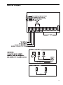
1
• W A R N I N G •
Please refer to the System Installation Manual for information on limitations regarding product use and
function and information on the limitations as to liability of the manufacturer.
TM
Long Range Radio
Alarm Transmitter
Installation
Manual
Version 1.4W
Table of Contents
FEATURES
1
Programmable via Keypad or Downloading Software ........................................................................................... 1
EEPROM Memory ................................................................................................................................................... 1
Static/Lightning Protection ..................................................................................................................................... 1
Supervision ............................................................................................................................................................ 1
Operation ............................................................................................................................................................... 1
SPECIFICATIONS
1
INSTALLATION
1
Mounting the LINKS2150 ....................................................................................................................................... 1
Power Terminals + 12v – ........................................................................................................................................ 2
TRBL Trouble Terminals ......................................................................................................................................... 2
YEL and PGM PANEL Terminals ............................................................................................................................ 2
COM Terminal ........................................................................................................................................................ 2
YEL and GRN KEYPAD Terminal ........................................................................................................................... 2
MOD OUT and V SUP Terminals ........................................................................................................................... 2
Keybus Connections .............................................................................................................................................. 2
PROGRAMMING THE LINKS2150
3
Programming Data ................................................................................................................................................. 3
Reviewing Programmed Data ................................................................................................................................ 3
HEX Data Programming ......................................................................................................................................... 3
LINKS2150 PROGRAMMING SECTIONS
4
[86] LINKS2150 Programming Sections for PC1580 ............................................................................................. 4
[803] LINKS2150 Programming Section for PC5010, PC5015, PC5008, PC1565, PC1565-2P, PC585 .............. 4
[96] [Installer Code] [96]
Restore LINKS2150 Factory Default Programming for PC1580 ............................................................................ 5
[993][Installer Code][993]
Restore LINKS2150 Factory Default Programming for PC5010 v1.1 or later,
PC5015, PC5008, PC1565, PC1565-2P, PC585 .................................................................................................... 5
Hardware Reset ..................................................................................................................................................... 5
FOR THE RECORD
6
LINKS2150 PROGRAMMING WORKSHEETS
7
[86] LINKS2150 Programming Sections for PC1580 ............................................................................................. 7
[803] LINKS2150 Programming Section for PC5010, PC5015, PC5008, PC1565, PC1565-2P, PC585 ............... 7
[01] RF Identification Code .................................................................................................................................. 7
[10] Maintenance Alarm Reporting Codes .......................................................................................................... 7
[11] Maintenance Restoral Reporting Codes ....................................................................................................... 7
[20] Module Configuration .................................................................................................................................... 7
[30] Call Direction Options ................................................................................................................................... 7
[81] Miscellaneous Alarm Reporting Codes ........................................................................................................ 8
[82] Miscellaneous Restoral Reporting Codes .................................................................................................... 8
[83] Miscellaneous Alarm Reporting Codes (PC1565 and PC5008 v2.0 panels only) ....................................... 8
[96] [Installer Code] [96]
Restore LINKS2150 Factory Default Programming for PC1580 ............................................................................ 8
[993][Installer Code][993]
Restore LINKS2150 Factory Default Programming for PC5010 v1.1 or later,
PC5015, PC5008, PC1565, PC1565-2P, PC585 ................................................................................................... 8
HOOK-UP DIAGRAM
This manual is for the LINKS2150 software version 1.4W.
9
Features
• Transmits alarm information to a long range radio network
• Varitech Transmission Format
Note: If automatic SIA is used in the panel, the
reporting codes that are to be sent by the LINKS2150
must still be programmed.
• May be used with the following DSC alarm control
panels:
• PC5010 v1.0 and up
• PC5015 v1.x and up
• PC5008 v2.x and up
• PC1580 v1.0 and up
• PC1565 v2.x and up
• PC1565-2P v2.2 and up
• PC585 v2.x and up
Programmable via Keypad or
Downloading Software
The LINKS2150 is complete with a default program and will
work with a minimum of programming. You can program
the LINKS2150 at any system keypad or using DLS-1 v6.7
or higher.
EEPROM Memory
The LINKS2150 uses EEPROM memory which will retain all
program information even if AC and battery power is
removed. The EEPROM memory can be reprogrammed
thousands of times.
Static/Lightning Protection
The LINKS2150 has been carefully designed and tested to
provide reliable protection against static and lightning
induced transients. Our special “Zap-Trac” circuit board
design catches high voltage transients right at the wiring
terminals, and transient protection devices are placed in
all critical areas to further reduce damaging voltages.
Supervision
• Low or disconnected external battery
• Loss of external AC power
• Security control panel connection supervision
Operation
• Long-range radio alarm transmitter
• 4 LINKS2150 Trouble Reporting Codes and Test
Transmission Reporting Code
Installation
Mounting the LINKS2150
Mount the LINKS cabinet in a convenient location next to
the already installed security system control panel cabinet.
As much as is reasonably possible, do not mount the
LINKS2150 near sources of interference. These include
sources of electrical noise such as computers, televisions
and electric motors in appliances and heating and air
conditioning units, as well as large metal objects like
heating ducts and plumbing which may shield the
antenna. If the cabinet must be located near such items,
the LINKS antenna may have to be mounted on a remote
bracket away from the cabinet. Whenever possible,
mount the LINKS2150 as close as possible to the
security system alarm control panel.
Mounting the Cabinet
If it is not already installed, install and test the security
system according to the instructions found in the security
system’s Installation Manual.
Remove the LINKS2150 and mounting hardware from the
cardboard packaging. Before attaching the cabinet to the
wall, press the supplied mounting studs into the raised
mounting holes from the back of the cabinet.
Mount the cabinet securely to the wall. It is recommended
that appropriate wall anchors be used when securing the
panel to drywall, plaster, concrete, brick or other similar
surfaces.
Install the LINKS2150 in the mounted cabinet. Locate the
antenna connection in the hole at the top of the cabinet
and press the LINKS2150 onto the nylon mounting studs.
Insert all cables into the cabinet and prepare them for
connection.
Secure the antenna to the LINKS2150 antenna connector.
Tighten the antenna “finger tight” only.
NOTE: An antenna should always be connected to the
LINKS2150 whenever it is operated. The unit will not
function properly and may be damaged if an antenna is
not installed.
Do not connect the power supply until all other wiring,
including the antenna connection, has been completed
and checked to ensure that it is correct. Incorrect
wiring connections may cause the LINKS unit to
operate improperly, or may damage the LINKS unit.
Specifications
• 2 negative triggered trouble inputs
- negative voltage trigger: 0 to 0.8 VDC
• Required power supply: 11.5 to 14VDC at 1A
A separate power supply must be used. Do not power
the LINKS2150 from the keybus.
• Trouble Output: 50mA
• Radio transmitter frequency: as specified on transmitter
• Antenna (not supplied):
- Larsen MHW-450, 50 Ω vertical antenna
- 450 - 470 MHz
• LINKS2150 cabinet dimensions:
- 11" high × 11.8" wide × 3.3" (279 mm × 300 mm ×
84mm)
• Cabinet colour: light beige
WARNING:
DO NOT connect both a
PC5400DVACS and a LINKS2150
module to the same system.
You can connect both a PC5400
printer module and a LINKS2150 to
the same system.
3
Power Terminals + 12v –
NOTE: Do not apply power to the unit until all wiring connections are completed and the antenna is attached to the unit.
Connect the power terminals (+ 12V –) to the BELL+ and
COM terminals or to a separate 11.5-14Vdc, 1A power
supply. If you will be using a local bell or siren, use a
separate power supply for the LINKS2150. Do not connect
the LINKS2150 to the Keybus RED terminal.
NOTE: The current drawn by the LINKS2450 and the siren(s)
connected to the Bell terminals must not exceed that specified
by the rating of the control panel. Refer to your control panel’s
Intallation Manual for more information.
The wiring between the LINKS2150 and the power supply
should not be longer than indicated in the table below:
Wire Gauge
AWG
22
20
18
Maximum Wire Length
feet / metres
15' / 4.5m
25' / 7.5m
40' / 12.0m
You can double the maximum wire length if you double the
conductors and connect them in parallel. Mount the
LINKS2150 as close to the power supply as possible.
TRBL Trouble Terminals
AC TRBL Input Terminal
The AC TRBL input terminal is used to report AC failure
troubles. If the power supply being used has an AC failure
trouble output, connect the output to the AC TRBL terminal.
When the AC TRBL terminal is shorted to ground, the
LINKS2150 will transmit the External AC Trouble reporting
code programmed in Section [10].
LB TRBL Input Terminal
The LB TRBL input terminal is to report low back-up battery
trouble. If the power supply being used has a low battery
trouble output, connect the output to the LB TRBL terminal.
When the LB TRBL terminal is shorted to ground, the
LINKS2150 will transmit the External Low Battery Trouble
reporting code programmed in Section [10].
OUT TRBL Output Terminal
The OUT TRBL output terminal will switch to ground when
the LINKS2150 detects a trouble condition. The OUT TRBL
terminal may be connected to a control panel zone
terminal to report LINKS2150 trouble conditions to the
security system, or the OUT TRBL terminal may be used to
activate a visual or audible trouble indicator.
This output may be used to activate a trouble indicator,
such as an LED indicator, a low current sounder, or an RM1 relay connected to another device.
YEL and PGM PANEL Terminals
The YEL PANEL terminal is used to connect the keybus
yellow from the PANEL.
The PGM PANEL terminal is used as a tamper to clear
tamper faults. This terminal must be shorted to the COM
terminal.
4
LINKS2150 shown mounted in cabinet
COM Terminal
When using the LINKS2150 with a security system,
connect the COM terminal to the negative DC power
supply terminal of the security system control panel.
YEL and GRN KEYPAD Terminal
The GRN KEYPAD terminal is used to connect the keybus
green from the PANEL.
The YEL KEYPAD terminal is not used.
MOD OUT and V SUP Terminals
These terminals connect the LINKS2150 to the radio
transmitter. These connections are made at the factory
and should not be altered.
Keybus Connections
Panel
Module
Keybus Red
Not connected
Keybus Black
To AUX-
Keybus Green
To GRN KEYPAD
Keybus Yellow
To YEL PANEL
Note: Do not connect the Keybus RED wire to the
LINKS2150.
Programming the LINKS2150
Reviewing Programmed Data
Program the LINKS2150 through Installer’s Programming
at a system keypad, or via DLS-1 v6.7 downloading
software.
• Enter the 2-digit number of the section to be reviewed.
For instructions on using DLS-1 v6.7, please refer to your
DLS-1 manual.
• LED keypads will display the first digit of data in the
section using zone lights 1 to 4 to represent the value,
in binary format. To advance the display to the next
digit, press the [F] key.
For instructions on keypad programming using Installer’s
Programming sections, please refer to section 4 “How to
Program” in your control panel Installation Manual.
To enter Installer’s programming:
1. Go to Installer’s Programming by entering
[*][8][Installer’s code].
2. For PC5015, PC5010, PC5008, PC1565, PC1565-2P
and PC585: Go to the LINKS2150 programming
section by entering [803].
For PC1580: Go to the LINKS2150 programming
section by entering [86].
Programming Data
Most sections contain groups of 2-digit entries. The
keypad will beep twice after each 2-digit group is entered.
When a section is entered, on LED keypads, zone lights 1
through 4 will indicate, in binary format, the value of the
first digit in the section. Refer to the Binary Data Display
chart below.
HEX data entry
Refer to HEX Data Programming
Value
Zone
Zone
Zone
Zone
0 1 2 3 4 5 6 7 8 9 A B C D E F
1
2
3
4
• LCD keypads will display the current data in the
programming section.
• At the end of the section, the keypad will beep several
times and then return to the Program Mode so that
another section can be selected for review or
programming.
HEX Data Programming
Certain programming sections may require the entry of
data in HEX (hexadecimal, or base 16) format. HEX
numbering uses the numbers 0 through 9 and the letters A
through F.
The letters A through F are represented by the number
keys 1 through 6. To enter data in HEX format, first press
the [ ] key. Press a number key from [1] to [6] to enter a
HEX digit then press the [ ] key again to return to
“decimal” values.
∗
∗
To enter HEX numbers:
∗ ∗
B ....... Enter [∗][2][∗]
C ....... Enter [∗][3][∗]
D ....... Enter [∗][4][∗]
E ....... Enter [∗][5][∗]
F ....... Enter [∗][6][∗]
A ....... Enter [ ][1][ ]
Zone Light ON
Zone Light OFF
If you wish to change the digit displayed, enter the new
digit. If you wish to keep that digit unchanged, skip over
the digit by pressing the [F] Key. Hexadecimal numbers
may also be entered in most sections. Refer to
Hexadecimal Data Programming for instructions.
When you are done programing the section, enter the 2digit number of the next section to be programmed.
5
LINKS2150 Programming Sections
These sections will only be available if a LINKS2150 v1.4W is connected to the Keybus.
[86] LINKS2150 Programming Sections
for PC1580
or
[803] LINKS2150 Programming Section
for PC5010, PC5015, PC5008, PC1565,
PC1565-2P, PC585
[01] 2150 Account Code
This 4-digit code is used to identify the system and is
transmitted when the LINKS2150 initiates
communications. Program a 4 digit code in this
section using only numbers from 0 to 9.
Note: An account number must be entered in this
section before communications through the
LINKS2150 can be used. Do not enter Hexadecimal
numbers in this section.
[10] Maintenance Alarm Reporting Codes
Program 2 digit reporting codes for each of the
following reporting codes
•
•
•
•
•
Internal Low Voltage
This code will be sent when the voltage supplied
to the LINKS2150 on the 12+ and 12 - terminals is
less than 10.5 VDC for more than 4 minutes
External AC Trouble
This code will be sent when the AC TRBL input
terminal is switched to ground.
External Low Battery Trouble
This code will be sent when the LB TRBL input
terminal is switched to ground.
Control Panel Connection Trouble
This code will be sent when connection is lost to
the panel on the Keybus for more than 60
seconds
Test Transmission
This code will be sent at the same interval as the
test transmission of the panel.
[11] Maintenance Restoral Reporting Codes
Program 2 digit reporting codes for each of the
following reporting codes
•
•
•
•
6
Internal Low Voltage
This code will be sent when the voltage supplied
to the LINKS2150 ion the 12+ and 12 - terminals
is restored to more than 11.6 VDC for more than 4
minutes
External AC Trouble
This code will be sent when the AC TRBL input
terminal is switched to ground.
External Low Battery Trouble
This code will be sent when the LB TRBL input
terminal is switched to ground.
Control Panel Connection Trouble
This code will be sent when connection is
restored to the panel on the Keybus for more
than 60 seconds.
[20] Module Configuration
Module configuration is set using Zone Lights as
shown below. After you enter section [20], the
options that are “on” will be shown either by the
corresponding zone light being on (LED keypads) or
the zone number being displayed (LCD keypads).
Press the corresponding number key to turn an option
ON or OFF. When finished, press [#].
Zone Light 1
ON Communications Enabled - The
LINKS2150 will initiate communications for
all events that the panel has reporting
codes programmed for.
OFF Communications Disabled - The
LINKS2150 will not initiate communications
for events that the panel has reporting
codes programmed for. Disable
communications to test the system.
Zone Light 2
OFF TRBL OUT Normally High Impedence - If
there are no trouble conditions detected by
the LINKS2150, the TRBL OUT terminal will
be high-impedence. The TRBL OUT
terminal will switch to ground when the
LINKS2150 detects a trouble condition.
ON TRBL OUT Normally Low - If there are no
trouble conditions detected by the
LINKS2150, the TRBL OUT terminal will be
low (ground). The TRBL OUT terminal will
switch to high-impedence when the
LINKS2150 detects a trouble condition.
Zone Light 3 to Zone Light 8 - For Future Use
[30] Call Direction Options
Program which of the following reporting code types
the LINKS2150 will send to the central station. Press
the number corresponding the the appropriate option
to turn the reporting type ON or OFF. When finished,
press [#].
Option
1
Alarm/restore reporting
2
Tamper/restore reporting
3
Opening/closing reporting
4
System maintenance reporting
5
System test transmission reporting
In most installations, you should program the tranmission of
alarm/restore reporting codes only. Your radio network has
limited bandwidth and capacity. The more signals each
LINKS2150 transmits, the fewer LINKS2150s you will be
able to install on your network.
NOTE: Sections [81] and [82] apply only to the PC1580
v1.x. All other panels will use the reporting codes that are
programmed for these events in the panel.
[81] Miscellaneous Alarm Reporting Codes
Program 2 digit reporting codes for each of the
following reporting codes
•
General Zone Fault Alarm
This code will be sent when the LINKS2150
receives a General Zone Fault Alarm event from
the PC1580.
•
General System Tamper Alarm
This code will be sent when the LINKS2150
receives a General System Tamper Alarm event
from the PC1580.
•
General System Supervisory Alarm
This code will be sent when the LINKS2150
receives a General System Supervisory Alarm
event from the PC1580.
[96] [Installer Code] [96]
Restore LINKS2150 Factory Default
Programming for PC1580
[993][Installer Code][993]
Restore LINKS2150 Factory Default
Programming for PC5010 v1.1 or later,
PC5015, PC5008, PC1565, PC1565-2P,
PC585
When this section is successfully entered, all programming
in the LINKS2150 will be returned to the factory defaults.
NOTE: This command is unavailable on PC5010 v1.0. If
v1.0 is used, a hardware default must be done.
Hardware Reset
On a PC5010 v1.0, a hardware reset must be done. There
is no software equivalent for PC5010 v1.0.
1. Remove all power to the LINKS2150.
[82] Miscellaneous Restoral Reporting Codes
Program 2 digit reporting codes for each of the
following reporting codes
•
General Zone Fault Restoral
This code will be sent when the LINKS2150
receives a General Zone Fault Restoral event
from the PC1580.
•
General System Tamper Restoral
This code will be sent when the LINKS2150
receives a General System Tamper Restoral
event from the PC1580.
•
General System Supervisory Restoral
This code will be sent when the LINKS2150
receives a General System Supervisory Restoral
event from the PC1580.
2. Disconnect all connections made to LB TRBL and
TRBL OUT.
3. Use a jumper to short LB TRBL and TRBL OUT
terminals.
4. Re-apply power.
5. Wait 10 seconds then remove the short.
NOTE: This can also be done if connected to PC1580.
[83] Miscellaneous Alarm Reporting Codes
(PC1565 v2.0 and PC5008 v2.0 panels only)
Program 2 digit reporting codes for the following (see your
Installation Manual for more information):
•Police Code: This code will be sent when the
LINKS2150 receives a Police Code event from the
PC1565 or PC5008.
•Delinquency Code: This code will be sent when
the LINKS2150 receives a Delinquency event from
the PC1565 or PC5008.
7
For The Record
Client ____________________________________________________________________________
Address _________________________________________________________________________
_________________________________________________________________________________
_________________________________________________________________________________
_________________________________________________________________________________
Installer ______________________________
Installation Date ________________________
Installer’s Code _______________________
Installer’s Lockout
DSC Control Panel _____________________
Software Version _______________________
On
Off
Notes
__________________________________________________________________________________
__________________________________________________________________________________
__________________________________________________________________________________
__________________________________________________________________________________
__________________________________________________________________________________
__________________________________________________________________________________
__________________________________________________________________________________
__________________________________________________________________________________
__________________________________________________________________________________
__________________________________________________________________________________
__________________________________________________________________________________
__________________________________________________________________________________
__________________________________________________________________________________
__________________________________________________________________________________
__________________________________________________________________________________
__________________________________________________________________________________
__________________________________________________________________________________
8
LINKS2150 PROGRAMMING Worksheets
[86] LINKS2150 Programming Sections for PC1580
or
[803] LINKS2150 Programming Section for PC5010, PC5015, PC5008, PC1565,
PC1565-2P, PC585
[01]
RF Identification Code
Default
F ______I
F ______I
F ______I
F
I______I
[10]
I______I______I______I______I
Maintenance Alarm Reporting Codes
I______I______I
Internal Low Voltage Trouble
I______I______I
External AC Trouble
I______I______I
External Low Battery Trouble
I______I______I
Control Panel Connection Trouble
I______I______I
Test Transmission
[11]
Maintenance Restoral Reporting Codes
I______I______I
Internal Low Voltage Trouble Restore
I______I______I
External AC Trouble Restore
I______I______I
External Low Battery Trouble Restore
I______I______I
Control Panel Connection Trouble Restore
[20]
Module Configuration
Default
[30]
Option ON
Option OFF
ON
I______I
Option
1
Communications enabled
Communications disabled
OFF
I______I
2
TRBL OUT Normally Low
TRBL OUT Normally High Impedence
OFF
I______I
3-8
For Future Use
Call Direction Options
Default
ON
ON
OFF
ON
ON
OFF
I_______I
I_______I
I_______I
I_______I
I_______I
I_______I
Option
1
2
3
4
5
6-8
ON
Alarm/restore reporting enabled
Tamper/restore reporting enabled
Opening/closing reporting enabled
System maintenance reporting enabled
System test transmission reporting enabled
For future use
OFF
Disabled
Disabled
Disabled
Disabled
Disabled
9
[81]
Miscellaneous Alarm Reporting Codes
I______I______I
General Zone Fault Alarm
I______I______I
General System Tamper Alarm
I______I______I
General System Supervisory Alarm
[82]
Miscellaneous Restoral Reporting Codes
I______I______I
General Zone Fault Restore
I______I______I
General System Tamper Restore
I______I______I
General System Supervisory Restore
Note: Sections 81 and 82 will be for 1580 v1.x only.
[83]
only)
Miscellaneous Alarm Reporting Codes (PC1565 and PC5008 v2.0 panels
Default = FF
I_______I_______I
Police Code
I_______I_______I
Delinquency Code
[96] [Installer Code] [96]
Restore LINKS2150 Factory Default Programming for PC1580
[993][Installer Code][993]
Restore LINKS2150 Factory Default Programming for PC5010 v1.1 or later, PC5015,
PC5008, PC1565, PC1565-2P, PC585
See page 5 for Hardware Reset procedure if using a PC5010 v1.0.
10
Hook-up Diagram
11
LIMITED WARRANTY
Digital Security Controls Ltd. warrants that for a period of twelve months from the date of purchase, the product shall be free
of defect in materials and workmanship under normal use and that in fulfilment of any breach of such warranty, Digital
Security Controls Ltd. shall, at its option, repair or replace the defective equipment upon return of the equipment to its repair
depot. This warranty applies only to defects in parts and workmanship and not to damage incurred in shipping or handling,
or damage due to causes beyond the control of Digital Security Controls Ltd. such as lightning, excessive voltage,
mechanical shock, water damage, or damage arising out of abuse, alteration or improper application of the equipment.
The foregoing warranty shall apply only to the original buyer, and is and shall be in lieu of any and all other warranties,
whether expressed or implied and of all other obligations or liabilities on the part of Digital Security Controls Ltd. This
warranty contains the entire warranty. Digital Security Controls Ltd. neither assumes, nor authorizes any other person
purporting to act on its behalf to modify or to change this warranty, nor to assume for it any other warranty or liability
concerning this product.
In no event shall Digital Security Controls Ltd. be liable for any direct, indirect or consequential damages, loss of
anticipated profits, loss of time or any other losses incurred by the buyer in connection with the purchase, installation or
operation or failure of this product.
WARNING: Digital Security Controls Ltd. recommends that the entire system be completely tested on a regular
basis. However, despite frequent testing, and due to, but not limited to, criminal tampering or electrical disruption, it
is possible for this product to fail to perform as expected.
FCC Compliance
CAUTION: Changes or modifications not expressly approved by Digital Security Controls Ltd. could void your authority to use this equipment.
This equipment has been tested and found to comply with the limits for a Class B digital device, pursuant to Part 15 of the FCC Rules. These limits are designed to provide
reasonable protection against harmful interference in a residential installation. This equipment generates, uses and can radiate radio frequency energy and, if not installed
and used in accordance with the instructions, may cause harmful interference to radio communications. However, there is no guarantee that interference will not occur in
a particular installation. If this equipment does cause harmful interference to radio or television reception, which can be determined by turning the equipment off and on, the
user is encouraged to try to correct the interference by one or more of the following measures:
• Re-orient the receiving antenna.
• Increase the separation between the equipment and receiver.
• Connect the equipment into an outlet on a circuit different from that to which the receiver is connected.
• Consult the dealer or an experienced radio/television technician for help.
The user may find the following booklet prepared by the FCC useful: “How to Identify and Resolve Radio/Television Interference Problems”. This booklet is available
from the U.S. Government Printing Office, Washington D.C. 20402, Stock # 004-000-00345-4
© 1998 Digital Security Controls Ltd.
1645 Flint Road, Downsview, Ontario Canada M3J 2J6
Telephone: (416) 665 8460 Fax: (416) 665 7498
29004011 R2
Printed in Canada