1
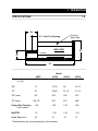
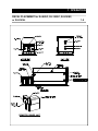
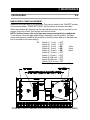
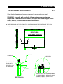
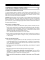
PLAY IT SAFE!
OPERATIONAL, MAINTENANCE,
AND INSTALLATION MANUAL
FOR
RJ-88SC
RJ-100SC
RJ-250SC
RJ-250VL
Includes HT (Hydraulic Tailgate) Units and SL
(StreamLine, Liquid Removal) Units
RAM-JET SELF-CONTAINED
COMPACTOR CONTAINER
VERNON, AL • FAYETTE, AL
YERINGTON, NV • CLEARFIELD, PA
Marathon Equipment Company • OMI Manual No. 0018, Rev. 9/03
CONTENTS
SECTION 1 - Operation
Introduction ............................................................................. ..................... 1-1
Specifications ............................................................................................... 1-2
Pre-Operation Instructions ....................................................................... 1-3
Operator Station .......................................................................................... 1-4
Operating Instructions For RJ-88SC, RJ-100SC, or RJ-250SC .................. 1-5
Operating Instructions For RJ-250VL .......................................................... 1-6
Optional Controls ......................................................................................... 1-7
Decals for RJ-88SC, RJ-100SC, RJ-250SC, or RJ-250VL .......................... 1-8
Decal Placement for RJ-88SC, RJ-100SC, RJ-250SC, or RJ-250VL ......... 1-9
Additional Decals and Decal Placement for Hydraulic Tailgate (HT) Units . 1-11
SECTION 2 - Maintenance
Lock-Out & Tag-Out Instructions ............................................................. 2-1
Periodic Maintenance .................................................................................. 2-2
Procedures (Hydraulic System Pressure Check) ........................................ 2-3
Procedures (Ram Control Timer Adjustment) ............................................. 2-4
Procedures (Cylinder Removal, Multi Cycle Timer Adjustment) .................. 2-5
Principles of Operation ................................................................................ 2-6
Tailgate Seal Replacement .......................................................................... 2-7
Charts .......................................................................................................... 2-8
Parts List ...................................................................................................... 2-10
Motor Control Panel .................................................................................... 2-11
Power Unit - Standard 5 HP......................................................................... 2-12
Power Unit - Standard 10 HP........................................................................ 2-13
Hydraulic Schematic - Typical ...................................................................... 2-14
Trouble-shooting Chart ................................................................................ 2-15
SECTION 3 - Installation
Concrete Pad Requirements ....................................................................... 3-1
Steel Installation Procedures ....................................................................... 3-2
Electrical & Hydraulic Installation ................................................................ 3-3
Through-The-Wall Power Unit Installation ................................................... 3-5
SECTION 4 - Hauler Information
Hauler Instructions - General ....................................................................... 4-1
Hauler Instructions - Door/Latch Operation ..................................................4-2
Hauler Instructions - Hydraulic Tailgate Operation (for optional HT units) ... 4-3
Hauler Instructions - TailGate Manitenance Bar (for optional HT units)........ 4-4
Hauler Instructions - Liquid Removal (for optional SL units) ........................ 4-5
© Copyright March 2002, Marathon Equipment Co.
1 OPERATION
INTRODUCTION
1-1
THANK YOU FOR PURCHASING A MARATHON SELF-CONTAINED
COMPACTOR/CONTAINER.
This product is designed to give you reliable service and superior performance for years
to come. To guarantee top performance and the safest operation of the compactor, each
person involved in the operation, maintenance, and installation of the compactor should
read and thoroughly understand the instructions in this manual and follow all warnings.
The employer involved in the operation, maintenance, and installation of the self-contained compactor/container should read and understand the most current version of the
following applicable standards:
ANSI Standard No. Z245.2, “Stationary Compactors Safety Requirements”
A copy of this standard may be obtained from:
ENVIRONMENTAL INDUSTRIES ASSOCIATION
4301 Connecticut Avenue, NW Suite 300
Washington D.C. 20008
OSHA 29 CFR, Part 1910.147, “The control of hazardous energy (lockout/tagout)”
Any service or repairs that go beyond the scope of this manual should be
performed by factory authorized personnel only.
IF YOU SHOULD NEED FURTHER ASSISTANCE, PLEASE CONTACT YOUR
DISTRIBUTOR. YOU WILL NEED TO PROVIDE THE COMPACTOR SERIAL
NUMBER, INSTALLATION DATE, AND ELECTRICAL SCHEMATIC NUMBER
TO YOUR DISTRIBUTOR.
IF YOU HAVE ANY SAFETY CONCERNS WITH THE EQUIPMENT, OR
NEED FURTHER INFORMATION, PLEASE CONTACT US AT:
Marathon Equipment Company
P.O. Box 1798
Vernon, Al 35592-1798
Attn: Field Service Department
1-800-633-8974
1 OPERATION
SPECIFICATIONS
1-2
“B”
Fire Port Each Side
“A”, Clear Top Opening
SIDE VIEW
COMPACTOR
“D”
CONTAINER
“C”
“E”
Model
88SC
30 1/2 x 48
100SC
35 x 60
“B”
70
76 1/8
68
76 1/2
“C”
42
49 5/8
52 1/2
51 1/2
“D” (max.)
96*
104*
104*
104*
254 1/2*
276*
275*
288*
Charge Box Capacity
(cubic yards)
1.00
1.50
1.90
1.90
WASTEC
.70
1.32
1.53
1.53
Cycle Time (sec)
44
37
33
37
“A”, Clear Top Opening
(L x W)
“E” (max.)
* Determined by the size and capacity of the container.
250SC
40.5 x 58
250VL
35 x 60
1 OPERATION
PRE-OPERATION INSTRUCTIONS
1-3
FEDERAL REGULATION PROHIBITS THE USE OF THIS
EQUIPMENT BY ANYONE UNDER 18 YEARS OF AGE.
STAY CLEAR OF ALL INTERNAL PARTS OF THE
SELF-CONTAINED COMPACTOR/CONTAINER
DURING OPERATION. FAILURE TO DO SO
COULD RESULT IN SERIOUS INJURY OR DEATH!
NEVER ENTER ANY PART OF THE COMPACTOR UNLESS THE DISCONNECT SWITCH HAS BEEN LOCKED-OUT AND TAGGED-OUT. See LockOut & Tag-Out instructions in the Maintenance section. Before starting the
compactor, be sure no one is inside. Be certain that everyone is clear of all
points of operation and pinch point areas before starting.
THE EMPLOYER SHOULD ALLOW ONLY AUTHORIZED AND TRAINED PERSONNEL TO OPERATE
THIS COMPACTOR. This compactor is equipped with a
key operated locking system. The key(s) should be in
the possession of only authorized personnel.
DO NOT REMOVE ACCESS COVERS EXCEPT FOR SERVICING. Only authorized
service personnel should be allowed inside. All access doors on the compactor body
should always be secured in place when the unit is operating. See Lock-Out & TagOut instructions in the Maintenance section.
ONLY AUTHORIZED PERSONNEL
SHOULD BE ALLOWED INSIDE THE
MOTOR CONTROL PANEL. The motor
control panel contains high voltage components. See Lock-Out & Tag-Out
Instructions in the Maintenance section.
If the compactor is equipped with a security gate or doghouse with security door, BE
SURE THAT THE SECURITY GATE OR DOOR IS CLOSED BEFORE THE COMPACTOR IS STARTED.
1 OPERATION
OPERATOR STATION
1-4
KEYED START SWITCH
REVERSE
OPERATOR
STATION
FOR 88SC, 100SC,
250SC, & 250 VL
EMERGENCY STOP
CONTROL DESCRIPTION FOR 88SC, 100SC, & 250SC
1. KEYED START SWITCH - This switch requires a key for operation. Insert the key
and turn clockwise to the start position. Depress and hold the key for one to two
seconds and release. The compactor will cycle one time (complete extension and
retraction of the ram) and stop. After use, turn the key to the counterclockwise
position and remove the key.
2. EMERGENCY STOP MUSHROOM HEAD PUSHBUTTON - When depressed, this
pushbutton will stop all powered operation of the compactor.
3. REVERSE PUSHBUTTON - This pushbutton will reverse the compaction ram
when depressed. The Keyed Start Switch must be energized for the REVERSE
button to operate. See the MANUAL OVERRIDE INSTRUCTIONS on the next
page for details of the operation.
CONTROL DESCRIPTION FOR 250VL
1. KEYED START SWITCH - This spring-loaded switch requires a key for operation.
Insert the key and turn clockwise to the start position and release. The compactor
will cycle one time (complete extension and retraction of the ram) and stop. After
use, remove the key.
2. EMERGENCY STOP MUSHROOM HEAD PUSHBUTTON - When depressed, this
pushbutton will stop all powered operation of the compactor.
3. REVERSE PUSHBUTTON - This pushbutton will reverse the compaction ram
when depressed. The Keyed Start Switch must be energized for the REVERSE
button to operate. See the MANUAL OVERRIDE INSTRUCTIONS on page 1-6 for
details of the operation.
1 OPERATION
OPERATING INSTRUCTIONS FOR RJ-88SC, RJ-100SC, & RJ-250SC
1-5
1. First, place the material to be discarded into the
compactor.
Note: If you are loading the compactor through a door or
gate, close it before starting the compactor. Refer to
“Optional Loading Configurations” in the Decal Placement
section to determine how your compactor is set up.
2. Insert the key into the key switch. Turn it clockwise and depress for 1 to
2 seconds and release. The unit will make one complete cycle, then
stop.
3. Repeat, if necessary, after the compactor has stopped.
4. When you have finished using the compactor, remove the key from the
key switch.
IN CASE OF EMERGENCY:
Push the large red button to STOP
MANUAL OVERRIDE INSTRUCTIONS (RAM STOP REAR ONLY - 88SC,
100SC, & 250SC)
If the ram is stopped in any position:
To move the ram forward, turn the key switch clockwise and depress.
To move the ram rearward, hold the reverse button down, turn and
depress the key switch, release the key switch, then release the
reverse button.
While the ram is moving:
To reverse the ram while it is moving forward, press the reverse button.
To cause the ram to move forward while it is moving rearward, depress
the key switch.
NOTE: Refer to Optional Controls for Manual Override on Ram Stop Forward Machines.
1 OPERATION
OPERATING INSTRUCTIONS FOR RJ-250VL
1-6
1. First, place the material to be discarded into the
compactor.
Note: If you are loading the compactor through a door or
gate, close it before starting the compactor. Refer to
“Optional Loading Configurations” in the Decal Placement
section to determine how your compactor is set up.
2. Insert the key into the key switch. Turn it clockwise and release. The unit
will make one complete cycle, then stop.
3. Repeat, if necessary, after the compactor has stopped.
4. When you have finished using the compactor, remove the key from the
key switch.
IN CASE OF EMERGENCY:
Push the large red button to STOP
MANUAL OVERRIDE INSTRUCTIONS (RAM STOP REAR ONLY - RJ-250VL)
If the ram is stopped in any position:
To move the ram forward, turn the key switch clockwise and release.
To move the ram rearward, hold the reverse button down, turn and
release the key switch, then release the reverse button.
While the ram is moving:
To reverse the ram while it is moving forward, press the reverse button.
To cause the ram to move forward while it is moving rearward, turn
and release the key switch.
NOTE: Refer to Optional Controls for Manual Override on Ram Stop Forward Machines.
1 OPERATION
OPTIONAL CONTROLS
1-7
1. SUSTAINED MANUAL PRESSURE CONTROL BUTTON (Hold-To-Run, ReleaseTo-Stop) - This option requires the compactor operator to remain at the push button
station while the compactor is in use. Actuation requires depressing the "Hold-ToRun" and "Start" buttons. After the unit has started, the "Start" button is released. If
the "Hold-To-Run" button is released, the unit will stop instantly.
2. CONTAINER FULL LIGHT - When the light is on, the container is full and is ready to
be emptied before its next use. To deactivate the light, depress the illuminated
emergency stop button. (The unit will not run while the light is on.)
3. ADVANCE WARNING LIGHT - When the light is on, the container is nearing the full
level and a pick up call should be made. At this time 200 PSI is left before the pressure switch is activated to shut the unit off and container is full. (Unit will run with
light on.)
4. RAM STOP FORWARD - When a machine with this option has been stopped, the
ram automatically begins to move rearward when restarted.
For the RJ-88SC, RJ-100SC, or RJ-250SC, to move the ram forward (when it is
stopped), hold the FORWARD button down, turn the key switch clockwise, depress
and release the key switch, then release the FORWARD button. To reverse the ram
while it is moving forward, depress the key switch. To cause the ram to move forward while it is moving rearward, press the FORWARD button.
For the RJ-250VL, to move the ram forward (when it is stopped), hold the FORWARD button down, turn and release the key switch, then release the FORWARD
button. To reverse the ram while it is moving forward, turn and release the key
switch. To cause the ram to move forward while it is moving rearward, press the
FORWARD button.
5. CYCLE TIMER - This option is used when more than one cycle is desired. The factory setting is for three strokes (adjustable).
6. ACCESS INTERLOCK - This is optional with units equipped with doors, chutes, or
access gates. It prevents the unit from operating while a door or gate is open.
1 OPERATION
DECALS for RJ-88SC, RJ-100SC, RJ-250SC, or RJ-250VL
1-8
WARNING DECAL REQUIREMENTS
When your compactor leaves the factory, several WARNING DECALS are installed for
protection. These labels are subject to wear and abuse due to the nature of the refuse
handling operation. THESE DECALS MUST BE MAINTAINED. Additional decals may
be purchased from your distributor or from Marathon Equipment Company.
Decal Number 06-0002 - RAM JET - MARATHON EQUIPMENT COMPANY
Decal Number 06-0003 - PATENT PENDING
Decal Number 06-0011 - MOTOR ROTATION
Decal Number 06-0038 - CAUTION: DO NOT REMOVE ACCESS COVER EXCEPT FOR SERVICING. FOLLOW
LOCK OUT- TAG OUT PROCEDURES.
Decal Number 06-0039 - DANGER: DO NOT ENTER.
Decal Number 06-0040 - CAUTION: KEEP OUT. (used on hoppers)
Decal Number 06-0043 - DANGER: 208 VOLTS, or
Decal Number 06-0044 - DANGER: 230 VOLTS, or
Decal Number 06-0045 - DANGER: 460 VOLTS.
Decal Number 06-0052 - CAUTION: GATE MUST BE CLOSED BEFORE OPERATING COMPACTOR. (used on
access gates)
Decal Number 06-0057 - CAUTION: STAND CLEAR WHEN CONTAINER IS BEING LIFTED.
Decal Number 06-0058 - ‘A’ PORT
Decal Number 06-0059 - ‘B’ PORT
Decal Number 06-0067 - CAUTION: DO NOT REMOVE THIS CONTAINER UNTIL REAR STOP IS INSTALLED.
Decal Number 06-0072 - QUICK CLEAN TANK
Decal Number 06-0093 - FIRE HOSE PORT.
Decal Number 06-0094 - NOTICE: WIPE OFF SEAL AFTER DUMPING.
Decal Number 06-0104 - HYDRAULIC TAILGATE OPERATING INSTRUCTIONS
Decal Number 06-0105 - DANGER: STAND CLEAR OF TAILGATE WHEN LIFTED.
Decal Number 06-0364 - SERIAL NUMBER PLATE
Decal Number 06-0121 - FEDERAL REGULATIONS PROHIBITS THE USE BY PERSONS UNDER 18 YEARS OF
AGE.
Decal Number 06-0124 - CYCON
Decal Number 06-0249 - DANGER: HAZARDOUS VOLTAGE ... LOCK OUT & TAG OUT.
Decal Number 06-1839 - AMERICAN FLAG
1 OPERATION
DECAL PLACEMENT for RJ-88SC, RJ-100SC, RJ-250SC,
or RJ-250VL
REMOTE POWER UNIT
1-9
1 OPERATION
DECAL PLACEMENT for RJ-88SC, RJ-100SC, RJ-250SC,
or RJ-250VL
1-10
OPTIONAL LOADING CONFIGURATIONS
06-0039
06-0039
THRU-THE-WALL
SECURITY CHUTE
DOGHOUSE
06-0039
EACH INSIDE WALL
06-0039
06-0039,
06-0052
DOCK
ACCESS GATE & HOPPER
06-0040
EACH OUTSIDE WALL
1 OPERATION
ADDITIONAL DECALS and DECAL PLACEMENT for
HYDRAULIC TAILGATE (HT) UNITS
1-11
In addition to the decals and their placement specified on the previous pages,
the self-contained units with the hydraulic tailgate option require the following
decals located as shown below.
Decal Number 06-0104 - CAUTION: STAND CLEAR OF TAILGATE WHEN LIFTED.
TRUCK MUST BE ON FIRM, LEVEL SURFACE BEFORE
LIFTING GATE. FRONT AND REAR HOLD DOWNS MUST
BE ENGAGED. TILT HOIST BEFORE LIFTING TAILGATE.
(Also, includes Operating Instructions for tailgate)
Decal Number 06-0105 -
DANGER: STAND CLEAR OF TAILGATE WHEN LIFTED.
HYDRAULIC COUPLING
06-0104
06-0105
SIDE VIEW
REAR VIEW
06-0105
BOTH SIDES
2 MAINTENANCE
LOCK-OUT & TAG-OUT INSTRUCTIONS
2-1
FOREWORD: Before entering any part of the compactor, be
sure that all sources of energy have been shut off, all potential hazards have been eliminated, and the compactor is
locked-out and tagged-out in accordance with OSHA and
ANSI requirements. If the ram is pressing against a load, move the
ram rearward before shutting the compactor down. The specific lockout and tag-out instructions may vary from company to company (i.e.
multiple locks may be required, or other machinery may need to be
locked-out and tagged-out). The following instructions are provided as
minimum guidelines.
INSTRUCTIONS
1. Move the main disconnect lever to the OFF position.
2. Padlock the disconnect lever with a keyed padlock and take the key
with you.
3. Along with the padlock, place an appropriate, highly visible, warning
tag on the disconnect lever. The tag should provide a warning such as:
“Danger: Do not operate equipment. Person working on equipment.” or
“Warning: Do not energize without the permission of ________________.”
4. After locking and tagging the compactor, try to start and operate the
compactor (as outlined in the Operating Instructions) to make sure the
lock-out and tag-out is effective. If the lock-out and tag-out is effective,
remove the key from the keyswitch and take with you.
ELECTRICAL: The motor control panel contains high
voltage components. Only authorized service personnel should be allowed inside the panel. Authorized service personnel should be allowed inside the panel only
after the compactor has been locked-out and taggedout.
HYDRAULIC: Stored hydraulic energy must
be removed from the compactor hydraulic circuit for complete lock-out and tag-out. Make
sure that this energy has been relieved by
manually depressing the solenoid valve pin
located in the center of each coil end of the
directional control valve.
SOLENOID
VALVE
VALVE PIN
POWER UNIT
2 MAINTENANCE
PERIODIC MAINTENANCE
2-2
WARNING: RAM SPEED ACCELERATES AS RAM RETRACTS. NEVER ENTER
ANY PART OF THE SELF-CONTAINED COMPACTOR/CONTAINER UNTIL THE
UNIT HAS BEEN LOCKED OUT AND TAGGED OUT.
MONTHLY
1. Check external hoses for chafing, rubbing, or other deterioration and damage.
2. Check for any obvious unsafe conditions in the compactor area.
3. Check oil level in hydraulic reservoir. Level should be 3/4 of sight gauge.
4. Clean out or wash out debris from behind compactor ram.
5. Lubricate the ram guidance tracks using the grease fittings on the compactor side
(For guided ram machines only), and check guide shoes for wear.
THREE MONTHS
1. Check functional operation of controls and options (stop button, timers, lights, etc.).
2. Check hydraulic cylinder, internal hoses, and connections for leakage; check hoses
for chafing and wear.
3. Lubricate the container door hinges.
ANNUALLY
1. Lubricate electric motor bearings annually per the manufacturers instructions.
FILTER MAINTENANCE
1. The hydraulic filter should be cleaned at regular yearly intervals.
2. The filter may be removed from the unit by disconnecting the union on the suction
side of the pump, removing the four bolts retaining the cover plate, and lifting the filter from the reservoir.
3. Care should be exercised in cleaning the fiIter to insure that the element is not torn.
Clean the element with a soft brush and standard industrial solvent.
4. Replace the filter after cleaning and tighten the union securely. Pump noise and a
"crackle" sound is most often caused by air entering the pump suction line.
Tightening the suction fittings will usually eliminate the problem.
RECOMMENDED OILS FOR THE HYDRAULIC SYSTEM
1. Union - Unax-46, Unax-AW46
2. Gulf - Harmony 47, Harmony 48-AW
3. Exxon - Teresstic 46, Nuto 46
4. Texaco - Rando 46
5. Chevron - AW 46
6. Shell -Turbo 46, Tellus 46
7. Quaker State - Dextron ll (ATF)
8. Citgo - Pacemaker 46, Tellus - AW46
9. Amoco - (Rycon)
2 MAINTENANCE
PROCEDURES
2-3
PRESSURE SETTING
When the hydraulic cylinders used in the RJ-88SC, RJ-100SC, RJ-250SC, and RJ250VL are fully extended or retracted, they bypass internally. This makes it impossible for the hydraulic system to reach relief pressure. Follow the recommendations
below for proper pressure setting.
1. Disconnect and lock out power using the procedure on page 2-1.
2. Using the quick disconnects, disconnect the hydraulic hoses from the compactor.
3. Remove the 1/4” plug from the check valve and install a 0-3000 psi pressure gauge.
4. Loosen the lock nut on the relief valve and turn the adjustment screw several turns
counter clockwise.
5. Remove the lock out provisions and turn the disconnect to the ON position. Start the
power unit using the OPERATING INSTRUCTIONS on page 1-5 or 1-6.
6. With the hoses disconnected, the power unit will build pressure. Adjust the relief
pressure up by turning the relief adjustment screw clockwise. Adjust the relief valve
to the desired pressure setting and tighten the lock nut. See chart below.
7. Press the EMERGENCY STOP button to stop the power unit, and relieve the stored
hydraulic energy as described on page 2-1.
8. Disconnect and lock out power as described in Step 1.
9. Remove the pressure gauge and replace the 1/4” plug in the check valve.
10. Reconnect the hydraulic hoses, and remove the lock out provisions.
PRESSURE SETTINGS
MODEL NO.
RJ-88SC
RJ-100SC
RJ-250SC
RJ-250VL
HP
GPM
5
10
10
10
6
10
10
10
RELIEF
VALVE
SETTING
1700
1850
1850
1850
RES.
CAP.
15
20
20
20
CYLINDER
BORE
ROD
STR
4
2 1/2
25
5
2 1/2
42
4
2 1/2
31 5/8
5
2 1/2
42
On units with the Advance Warning Light, set the pressure 200 PSI below pressure switch setting.
Includes HT units & SL units.
2 MAINTENANCE
PROCEDURES
2-4
RAM CONTROL TIMER ADJUSTMENT
Determine the cycle time of your machine. This can be found in the “CHARTS” section
of this manual under “TIMER SETTINGS”. Set the timers as shown in the chart.
When the switches are properly set, the ram will fully extend, stop for one-half to one
second, then fully retract, stop and the unit will shut down.
NOTE: As time passes, the cycle time may change and need to be readjusted.
To set a timer, move the appropriate binary switches to the ON position. The timer
switch settings are cumulative (all switches in the ON position add up to the total number of seconds for the timer setting).
Ex. : Switch 1 ( 1 sec) = OFF
Switch 2 ( 2 sec) = OFF
Switch 3 ( 4 sec) = ON
4 sec
Switch 4 ( 8 sec) = ON
8 sec
Switch 5 ( 16 sec) = ON
16 sec
Switch 6 ( 32 sec) = OFF
Switch 7 ( 64 sec) = OFF
Switch 8 (128 sec) = OFF
Switch 9 (256 sec) = OFF
Switch 10 (512 sec) = OFF
Timer Setting
=
28 sec
PRINTED CIRCUIT BOARD (LOCATED IN MOTOR CONTROL PANEL)
2 MAINTENANCE
PROCEDURES
2-5
CYLINDER REMOVAL INSTRUCTIONS
1. Remove access covers from compactor.
2. Remove hoses (4, for 88SC & 250SC, 100SC & 250VL).
3. Remove cylinder pins.
4. Remove cylinders (2, for 88SC & 250SC, 1, for 100SC & 250VL).
5. To install the cylinders, reverse the above steps.
MULTI-CYCLE TIMER ADJUSTMENT - OPTION
Determine the cycle time of your machine. This can be found in the CHARTS section of
this manual under TIMER SETTINGS. Next multiply the cycle time by the number of
cycles the machine should run and subtract one fourth of the cycle time. This is the
cumulative number of seconds for which to set the switches.
EXAMPLE: Cycle time of machine ........................... = 28 sec
Desired number of cycles ...................... = 3
Total seconds for 3 cycles (28 X 3) ........ = 84 sec
One fourth of cycle time (28/4) ...............= 7 sec
Number of seconds to set timer (84 - 7) = 77 sec
RAM STOP FORWARD - OPTION
To convert the RJ-88SC, RJ-100SC, RJ-250SC, and RJ-250VL to Ram Stop Forward,
move the purple solenoid wire from terminal # 8 to terminal # 10. Reset timers by the
settings shown in the TIMER SETTINGS section under CHARTS in this manual.
Change the “START-FORWARD” key lock push button legend to “START-REVERSE”.
Change the “REVERSE” button legend to “FORWARD”.
WARRANTY AND SERVICE ON MOTORS
If the compactor motor fails under warranty, have it checked by a qualified electrician or
service person. If there is no problem with fuses or wiring, the motor should be taken to
the nearest authorized motor warranty shop. If you do not have a list of qualified shops,
contact Marathon Equipment Co. The motor warranty shop will be able to inspect the
motor and determine if it is factory defective. If the motor failed due to defects in material or workmanship, the warranty shop will repair or replace the motor at the manufacturers expense. If motor failure was not due to defective material or workmanship, it will be
repaired only if customer agrees to pay for expenses. Marathon Equipment Co. will not
absorb cost for pickup and delivery to service centers. Removal and reinstallation are
covered in the standard warranty policy.
2 MAINTENANCE
PRINCIPLES OF OPERATION
2-6
STANDARD SYSTEM OPERATING CHARACTERISTICS, 5 hp & 10 hp
The system uses special cylinders to move the ram and two timers to control the operation of the ram. When the hydraulic cylinders used in the RJ-88SC, RJ-100SC, RJ250SC, and RJ-250VL are fully extended or retracted, they bypass internally. This
makes it impossible for the hydraulic system to reach relief pressure. The sequence of
operation for this system is as follows:
Upon startup, a contact is made that energizes the motor starter, starting the electric
motor and at the same time energizing T1 timer coil. When T1 is energized, the valve
solenoid shifts the valve so that the hydraulic oil is directed to extend the cylinder which
extends the ram. When T1 timer times out, the contacts reverse causing T2 timer to
energize and the solenoid to shift the valve into the reverse position. In this position, the
valve directs the hydraulic oil into the front end of the cylinder causing the cylinder to
retract, therefore causing the ram to retract. When T2 timer times out, the motor starter
contact is opened causing the motor starter to shut down, therefore causing the
motor/power unit to shut down.
2 MAINTENANCE
TAILGATE SEAL REPLACEMENT
2-7
When the door/tailgate seal becomes damaged or worn, replace the seal.
WARNING: For units with hydraulic tailgates, before performing any
inspection or maintenance on the seal, support the raised tailgate with a
crane, forklift, or other positive maintenance prop.
l WHEN REMOVING THE OLD SEALS (TOP & BOTTOM), MARK THE POSITION OF THE SEAL
JOINTS. PRY THE SEAL RETAINER UP SLIGHTLY TO ALLOW REMOVAL OF THE OLD SEALS.
l WHEN INSTALLING THE NEW SEALS, JOIN THE SEALS AT THE SAME POSITIONS.
FRONT VIEW DOOR SEAL ON DOOR
A
A
PRY BAR
NEW SEAL
NEW SEAL
SEAL RETAINER PRY SLIGHTLY
UPWARD SO
NEW SEAL CAN
BE INSERTED
SECTION A-A
USE A PLASTIC OR RUBBER HAMMER
TO TAMP THE SEAL RETAINER SNUG
AGAINST THE SEAL ALL THE WAY
AROUND THE SEAL(S)
2 MAINTENANCE
CHARTS
2-8
TIMER SETTINGS
MODEL NO.
RJ-88SC
RJ-100SC
RJ-250SC
RJ-250VL
RAM STOP REAR
T1
T2
RAM STOP FORWARD
T1
T2
27
21
19
21
17
16
13
16
17
16
13
16
27
21
19
21
Includes HT units and SL units.
FUSES AND CIRCUIT BREAKERS
VAC
FULL
LOAD
AMP.
DUAL ELEMENT
FUSE
MAX. SIZE
5 HP, 1 PH
208
230
22.0
20.8
50
45
80
70
60
60
5 HP, 3 PH
208
230
460
575
13.8
13.4
6.7
5.4
30
25
15
10
40
40
20
15
30
30
30
30
10 HP, 1 PH
208
230
43.0
39.0
100
90
125
125
100
100
10 HP, 3 PH
208
230
460
575
27.5
26.4
13.2
11.4
50
50
25
20
80
70
35
30
60
60
30
30
MOTOR
SIZE
CIRCUIT
BREAKER
MAX. SIZE
SERVICE
DISCONNECT
AMP.
2 MAINTENANCE
CHARTS
2-9
WIRE SIZES
THW Copper 75°C (165°F)
MOTOR
SIZE
VOLTAGE
LENGTH
TO 100’
TO 200’
TO 300’
5 HP, 1 PH
208
230
8
8
6
6
4
4
5 HP, 3 PH
208
230
460
575
10
10
12
12
6
8
12
12
4
6
10
12
10 HP, 1 PH
208
230
4
4
1
2
1/O
1/O
10 HP, 3 PH
208
230
460
575
6
8
12
12
4
4
10
12
2
3
8
10
MOTOR STARTERS AND HEATER ELEMENTS
MOTOR
SIZE
VOLTAGE
STARTER
SIZE
HEATER ELEMENT
A-B JOSLYN CLARK
5 HP, 1 PH
208
230
2
2
W-61
W-60
2452
2451
5 HP, 3 PH
208
230
460
575
1
1
1
1
W-55
W-55
W-46
W-44
2447
2446
2438
2435
10 HP, 1 PH
208
230
3
3
W-66
W-65
N/A
N/A
10 HP, 3 PH
208
230
460
575
2
2
1
1
W-63
W-62
W-55
W-53
2454
2454
2446
2445
2 MAINTENANCE
PARTS LIST
PART #
02-0050
02-0157
02-0184
02-0197
02-0198
02-0204
02-0214
02-0215
02-0244
02-0267
02-0284
02-0295
02-0305
02-0242
99-7778
02-4037
03-0191
03-0195
03-0196
03-0197
03-0288
03-0345
03-0458
03-0488
03-0927
03-0928
03-0929
03-0936
03-0937
03-1187
04-0210
04-0211
04-0300
04-0301
04-0310
04-0311
04-0330
05-0001
05-0224
05-0247
06-0006
2-10
PART DESCRIPTION
88SC 100SC 250SC 250VL 88HT 250HT
SUCTION FILTER
X
X
X
X
X
X
DIRECTIONAL VALVE
X
X
X
X
X
X
CHECK VALVE
X
X
X
X
BREATHER
X
X
X
X
SIGHT GAUGE
X
X
CHECK VALVE
X
X
RELIEF VALVE
X
X
X
X
X
X
SIGHT GAUGE
X
X
X
X
HUB COUPLING
X
X
X
X
PUMP, 10 GPM
X
X
X
X
FLOW CONTROL VALVE
X
X
COIL, SOLENOID
X
X
X
X
X
X
BREATHER
X
X
HUB COUPLING
X
X
PUMP, 6 GPM
X
X
PUMP/MOTOR ADAPTER
X
FUSE, 2 AMP.
X
X
X
X
X
X
SWITCH, KEYLOCK START
X
X
X
X
X
SWITCH, MUSHROOM STOP
X
X
X
X
X
SWITCH, BLACK REVERSE
X
X
X
X
X
TRANSFORMER
X
X
X
X
X
X
MOTOR, 10 HP
X
X
X
X
P.C. BOARD
X
X
X
X
X
X
FUSE, 1 1/2AMP.
X
X
X
X
X
X
SWITCH, KEYED START
X
SWITCH, BLACK REVERSE
X
SWITCH, MUSHROOM STOP
X
CONTACT, N.O. F/CONTROL SWITCH
X
CONTACT, N.C. F/CONTROL SWITCH
X
MOTOR, 5 HP
X
X
CYLINDER F/TAILGATE
X
X
SEAL KIT F/04-0210
X
X
CYLINDER
X
X
SEAL KIT F/04-0300 & 04-0330
X
X
X
X
CYLINDER
X
X
SEAL KIT F/04-0310
X
X
CYLINDER
X
X
TURNBUCKLE, DOOR LATCH
X
X
X
X
SWINGBOLT, DOOR LATCH
X
X
TAILGATE SEAL
X
X
X
X
X
X
SHOE, CAST IRON, SHORT
4
4
4
4
4
4
2 MAINTENANCE
MOTOR CONTROL PANEL - TYPICAL
2-11
*
* Motor Starter brand and size determined by model number and voltage.
2 MAINTENANCE
POWER UNIT - STANDARD 5 HP
2-12
DETAIL B
DETAIL B
DRAIN
PLUG
DETAIL A
DETAIL A
2 MAINTENANCE
POWER UNIT - STANDARD 10 HP
2-13
2 MAINTENANCE
HYDRAULIC SCHEMATIC - TYPICAL
* SINGLE CYLINDER UNIT SHOWN. FOR DUAL CYLINDER
UNITS, CONNECT IDENTICAL CYLINDER IN PARALLEL.
2-14
2 MAINTENANCE
TROUBLE-SHOOTING CHART
2-15
PROBLEM
CAUSE
SOLUTION
UNIT WILL NOT START
( 1) No electrical power to unit
( 1A) Turn on main disconnect
( 1B) Replace fuses or reset breakers
( 2A) Check primary and secondary
sides of transformer
( 2B) Check for correct voltage. Check
control fuses.
( 2C) Check stop button
( 2D) Check start button to be sure contact closes when depressed
( 3A) Check heater resets
( 2) No electrical power to control
circuit
( 3) No electrical power to motor
UNIT WILL NOT CONTINUE RUNNING
WHEN START BUTTON IS RELEASED
( 1) Motor starter is in-operative
( 2) Motor starter auxiliary contacts are inoperative
( 3) Reverse Button is inoperative
( 4) Secondary contact on start button
is inoperative
MOTOR RUNS BUT RAM DOES NOT MOVE
NORMALLY
( 1) Insufficient oil in reservoir
( 2) Low relief pressure
( 3) Oil leakage in cylinder
( 4) Defective pump
( 5) Oil leakage from hose fittings
( 6) Low voltage
( 7) Pump may be driven in the wrong
direction of rotation
( 8) Shaft broken, or shaft key sheared
( 9) Intake pipe from reservoir blocked, or oil
viscosity too heavy to prime
( 10) Intake air leaks (foam in oil or sounds
like gravel in pump)
( 11) Units shift slowly
( 12) Valve response sluggish
( 13) Loose hub coupling
UNIT WILL NOT REVERSE
( 1) Solenoid valve is in-operative
( 2) Reverse button in-operative
( 1A) Check motor starter coil & wiring
( 2A) Check motor starter contacts and
wiring
( 3A) Check reverse button to be sure
contacts are closed
( 3B) Check wiring
( 4A) Check contact, wired black and
orange, to be sure it is operating
properly
( 4B) Check wiring
( 1A) Fill reservoir with oil
( 2A) Check relief pressure (refer to
PROCEDURES-HYDRAULIC PRESSURE
CHECK and PRESSURE SETTINGS for
correct pressure.
( 2B) Clean orifice in relief valve and
reset pressure
( 2C) Check 'O" rings on relief valve for
damage or leakage
( 3A) Check cylinder for bypassing
( 3B) Replace seal kit, inspect rod and
cylinder tube for scoring or nicks
( 3C) Replace cylinder
( 4A) Replace pump
( 5A) Tighten hose fittings
( 6A) Check voltage
( 7A) Stop immediately to prevent seizure.
Check direction of drive rotation (proper rotation direction is indicated by
arrow on motor)
( 8A) Visually inspect motor and pump shaft
and hub couplings for damage. Replace
if necessary.
( 9A) Drain system. Add clean fluid of proper
viscosity and specifications. Filter as
recommended. Check system filter for
cleanliness.
(10A) Check intake connections. Tighten
securely
( 11A) Flow control valve (restrictor) clogged ,
remove and clean orifice.
( 12A) Contaminated oil-drain and flush
system.
( 12B) Inadequate voltage, check voltage,
check coil
( 12C) Disassemble valve and clean
( 13A) Tighten set screws on hub coupling
halves
( 1A) Check coil in solenoid valve
( 2A) Check reverse button contacts
2 MAINTENANCE
TROUBLE-SHOOTING CHART
2-16
PROBLEM
CAUSE
SOLUTION
PUMP MAKES NOISE-SOUNDS
LIKE GRAVEL
( 1 ) Partly clogged intake strainer or
restricted intake pipe
( 2) Defective bearing
( 3) Air leak at pump intake pipe joints
( 1A) Pump must receive intake fluid freely or
cavitation results. Drain system, clean
intake pipe and clean or replace strainer
( 2A) Replace pump
( 3A) Tighten joints as required.
PUMP SHAFT SEAL LEAKING
( 1) Seal worn or damaged
( 1A) Replace seals or pump.
EXCESSIVE HEAT
( 1) Continuous running
( 1A) When over 140 degrees F or hot in
comparison with circuit lines, pump
should be shut down immediately.
Before restarting, insure that fluid cooling capacity is adequate to remove system generated heat.
( 1B) Install oil cooler (air or water type)
( 1C) Install oil temperature shut down switch
( 1D) Check to be sure CYCON Power Pack
has not been exchanged for Pressure
Shifting Power Pack.
( 2A) Replace with larger hydraulic lines
( 3A) Use lower viscosity oil
( 2) Undersized hydraulic lines
( 3) High ambient temp in relation to
oil temp.
( 4) Excessive system leakage
RAPID WEAR
( 1) Abrasive matter in the hydraulic oil being
circulated through pump
( 2) Viscosity of oil too low at working
conditions
( 3) Pressure too high
( 4) Air recirculation causing pump noise
ERRATIC OPERATION
( 1) Valve sticking or binding
( 2) Viscosity of oil too high
( 3) Air in system
( 4) Low oil
( 5) Low voltage
OVERLOADS TRIP FREQUENTLY
( 4A) Check system for bypassing or
leaks
( 1A) Install adequate filter or clean.
( 1B) Replace oil more often and clean tank
( 2A) Replace oil with factory recommended .
( 3A) Reduce pump pressures to factory
specifications.
( 4A) Tighten all fittings.
( 1A) Disassemble & clean as necessary
( 2A) Change oil to factory recommended viscosity
( 3A) Check for leaks, tighten fittings
( 4A) Fill reservoir with oil
( 5A) Check primary & secondary sides of
transformer for correct voltage.
( 1A) Check for correct voltage (incoming
power.)
( 1B) Check fuses or breakers at disconnect
( 1C) Check heater elements to be sure they
are tight
( 1D) Check wiring from starter to motor to
make sure all connections are tight
( 1E) Check motor leads to be sure all connections are tight surges or voltage
NOTE: Excessive overload tripping and/or
motor or coil failures may occur if voltage
surges or voltage drops are frequent in your
area. This circumstance can be remedied by
the installation of phase protectors which drop
power to the motor if surges are present.
3 INSTALLATION
CONCRETE PAD REQUIREMENTS
3-1
CAUTION:
REVIEW THIS MANUAL BEFORE MAKING THE INSTALLATION. STUDY THE JOBSITE AND INSTALLATION REQUIREMENTS CAREFULLY TO BE CERTAIN ALL
NECESSARY SAFEGUARDS AND OR SAFETY DEVICES ARE PROVIDED TO
PROTECT ALL PERSONNEL AND EQUIPMENT DURING THE INSTALLATION AND
AS A COMPLETED SYSTEM. SPECIAL ATTENTION IS DIRECTED TO THE
EXTRACT FROM AMERICAN NATIONAL STANDARDS INSTlTUTE Z245.2 .
These operating instructions are not intended as a substitute for training and experience in proper use and safety procedures in operating this equipment.
Marathon Equipment Co. does not assume responsibility for the installation procedures of this equipment. Conformance to applicable local, state, and federal
laws concerning installation rests with the customer.
CONCRETE PAD
1. Preferred dimensions of the concrete pad are 10'0" wide and a length of 5'0" greater
than the length of the compactor/container. It should be level and of minimum 3000
PSI concrete steel reinforced, 6" thick. It is preferred that the concrete pad be flush
with the surrounding ground level. NOTE: Units with four ground rollers must be
installed on a level pad.
2. To provide accessibility, concrete pad should be positioned to allow 2'0" between
machine and building wall if installed parallel with building. Allow a minimum of 45'
of clear space from end of pad for container handling vehicle.
Note: The clearances given are minimums. Your installation may require greater
clearances depending on the site and the hauling equipment that will be used.
CONTAINER GUIDES
If container guides (optional) are used with the self-contained units, the guides should
be anchored to the concrete pad using 3/4" X 6" anchor bolts. These bolts should be
concrete anchors or expansion type anchor bolts. To allow for construction variations, it
is best if these holes are drilled in the concrete after prelocating the container guides in
their desired location. Drill holes and place anchor bolts in each location provided on
the guides. When the guides have been placed in position, and the anchor bolts have
set, tighten all nuts securely.
3 INSTALLATION
STEEL INSTALLATION PROCEDURES
3-2
DOCK INSTALLATION
If the appropriate accessories are ordered from Marathon Equipment Co., the compactor/container will be furnished with either a four-sided hopper or a three-sided hopper with a hinged gate. THESE ACCESSORIES SHOULD NOT BE ALTERED AS THEY
ARE MANUFACTURED IN ACCORDANCE WITH THOSE STANDARDS WHICH PREVAIL AT THE TIME OF MANUFACTURE.
If the compactor/container cannot be directly abutted to the dock or if there is any difference in height between the dock and the compactor/container, an appropriately sturdy
transition section should be provided by the customer and securely affixed to the dock.
Along with the transition section, a compactor/container guidance/stop mechanism
should be installed to assure that the unit does not bottom out against the transition
section or dock during dock placement (See ANSI Z245.2 Safety Standards). Optional
container guides with stops are available from Marathon and are recommended for
proper dock placement of the compactor/container.
CHUTE-FED INSTALLATION
Compactors installed in this arrangement are normally fed "through-the-wall". The lower
edge of the access hole in the wall should be a MINIMUM of 42" (and, if possible, not
more than 58") from the inside floor level. A security door (in accordance with local
code) shouId be installed in the walI opening. In the absence of a local code, this door
should be constructed of 3/16" thick steel or of steel hollow core design and be lockable
from the inside of the building .
DECALS
Be certain that the appropriate decals are in their proper locations at all times on the
machine. For decal locations, see “DECALS” and “DECAL PLACEMENT” in the
Operation section of this manual.
NOTE: Installation is not complete until all decals are in place.
3 INSTALLATION
ELECTRICAL & HYDRAULIC INSTALLATION
3-3
The motor control panel contains high
voltage components. Only authorized
service personnel should be allowed
inside. See Lock-Out & Tag-Out instructions in the maintenance section.
A lockable fused disconnect switch (customer furnished) must be installed and be within
sight of the compactor motor control panel location, not to exceed 50'0" from the compactor. This fused disconnect switch should be sized in accordance with the compactor
(see Fuse and Circuit Breaker Chart).
CAUTION: All equipment should be grounded per National Electric Code.
REMOTE POWER PACK INSTALLATION
1. The remote power pack should be installed and anchored as required by the customer. If the operator station is mounted in the face of the motor control panel, be
certain these controls are located as to be in a convenient, but not hazardous, location to the customer.
CAUTION: Operator Station must be located so that the Mushroom (Emergency)
Stop Button is readily accessible to the operator and within three (3) feet of the
charging chamber access door. If installation requires the operator station to be
located in a more remote area, a second Emergency Stop Button should be added
and installed in the manner described above.
2. For a through-the-wall power pack installation, see the diagram THROUGH-THEWALL POWER UNIT INSTALLATION at the end of this manual. Special care should
be taken to protect the hoses from abrasive objects.
3. Connect the hydraulic hoses to the power pack, exercising care to follow the port
decals (A or B) on the packer and the power pack. In the event the decals have
been obliterated, the hose leading from the rear of the cylinder should be installed
in the side port of the block to which solenoid valve is bolted (A Port). The hose
leading from rod end of the cylinder should be connected to the end of the block to
which the solenoid valve is bolted (B Port). Refer to Power Unit diagrams in the
Maintenance section of this manual.
3 INSTALLATION
ELECTRICAL & HYDRAULIC INSTALLATION
3-4
PUSHBUTTON OPERATOR STATION
If a remote operator station is furnished, it will be factory wired using Sealtite. If it is
necessary to disconnect it from the wires (to install the operator station inside a building), exercise care that these wires are reconnected as originally furnished. (Check
local codes to be certain that Sealtite is acceptable.)
CAUTION: Operator Station must be located so that the Mushroom (Emergency) Stop
Button is readily accessible to the operator and within three (3) feet of the charging
chamber access door. If installation requires this operator station to be located in a
more remote area, a second Emergency Stop Button should be added and installed in
the manner described above.
ELECTRICAL CONNECTIONS
1. Run power lines, between fused disconnect switch (customer furnished) and compactor's motor control panel, in accordance with local electrical codes, using knockouts in bottom of motor control panel. See Fuse & Circuit Breaker Chart for Motors
and Wire Size Chart, in the Maintenance Section, to determine the proper service
disconnect amperage rating and the proper wire size.
NOTE: High legs should be installed to L3 on motor starter.
2. Check voltage at fused disconnect switch to be certain it is the same as is shown on
compactor or remote power pack. If voltage is correct, put fused disconnect switch
in "ON" position.
START-UP INSTRUCTIONS
1. With the ram fully retracted, check to be sure the oil reservoir is full to the 3/4 level
on the sight gauge (Refer to the maintenance chart for hydraulic oil recommendations). The hydraulic system pressure has been factory set and the entire unit has
been operated prior to shipment.
2. CAUTION: MAKE SURE PERSONS AND MATERIAL ARE CLEAR OF CHARGE
BOX AREA.
3. Depress the start button and check the pump shaft for proper rotation.
CAUTION: If the pump rotates backward, stop immediately. The pump will be
damaged if it is operated in reverse even for short periods. Reversing any two
incoming power lines will change the motor/pump rotation.
4. Make sure that the operators are trained in the proper use of this equip-
ment.
3 INSTALLATION
THROUGH-THE-WALL POWER UNIT INSTALLATION
3-5
If the remote power unit is to be mounted through-the-wall, the following list of material
and diagram is the suggested method.
List of Material
Item No.
Quantity
1
2
2
2
3
2
4
2
5
4
6
3
Description
Hydraulic Hose, Hi-Pressure (sized to power unit*), 36” long
Pipe, Sch 80 (sized to power unit*), 36” long
Hydraulic Hose, Hi-Pressure (sized to power unit*), 48” long
Steel plate with holes for Item No. 2, 3/16” x 8” x12”
Coupling, Female (sized to fit hose & pipe*)
Coupling, Male x Female Swivel
* 1/2” for runs of 20’-0” or less. Consult factory for longer runs.
WALL
TOP VIEW COMPACTOR
POWER
UNIT
ITEM #3
A
B
B
ITEM #1
A
CYLINDER
ITEM #6
ITEM #5
ITEM #4
EACH SIDE
ITEM #2
4 HAULER INFORMATION
HAULER INSTRUCTIONS - GENERAL
4-1
Before hauling to the landfill:
1. Disconnect all hoses and electrical connections (if applicable) between the power
unit and the compactor. Make sure they are laid in an area where they will not get
damaged.
2. Close and secure any hopper doors or gates.
3. Make sure that the container door safety chain is secured in the keyhole on the
latch side of the container floor.
4. If the unit is a Streamline model (SL), disconnect any drain hose(s) connected to
the unit and plug all ports.
5. Make sure that the hoist lifting the unit is compatible with the understructure
on the unit.
NOTE: Hold-downs should be used to secure the front and rear of the of the
container understructure to the hoist.
At the landfill:
SEE THE NEXT PAGE FOR DOOR AND LATCH OPERATION INSTRUCTIONS.
1. To prevent leakage, the door seal and mating surface should be wiped clean and
inspected after the unit has been emptied. When cleaning the seal on units with the
hydraulic tailgate option,
WARNING: NEVER place any part of your body between the tailgate and the
container. Use a mop or similar cleaning device with a long handle to clean
the seal. Close inspection of the seal should be done only after the container
has been lowered to a level position and the raised tailgate has been supported with a crane, forklift, or other positive maintenance prop.
Replace the seal if damaged.
After returning from the landfill:
1. After setting the unit down, reconnect all hoses and electrical connections (if applicable) to the compactor. Make sure they are not laying across sharp corners or any
abrasive surface.
2. Close and secure any hopper doors or gates.
3. Make sure that the container door safety chain is secured in the keyhole on the
latch side of the container floor.
4. If the unit is a Streamline model (SL), connect any drain hose(s) to the unit.
4 HAULER INFORMATION
HAULER INSTRUCTIONS - DOOR/LATCH OPERATION
4-2
CONTAINER
DOOR
AUTO RELATCH
SAFETY CHAIN ALWAYS FASTEN
CHAIN IN KEYHOLE
WHEN DOOR IS
CLOSED. WHEN THE
DOOR IS OPEN,
SECURE THE CHAIN
IN THE KEYHOLE ON
THE HINGE SIDE OF
THE CONTAINER
FLOOR.
AUTO RELATCH
IN POSITION TO
OPEN DOOR
AUTO RELATCH
IN POSITION TO
GRAB AND HOLD
DOOR DURING
DOOR CLOSING
LATCH ASSEMBLY ACTUATED
BY RATCHET
LATCH SIDE VIEW
OF CONTAINER
RATCHET FOR OPENING AND CLOSING
THE LATCH ASSEMBLY
ROTATE THE AUTO RELATCH
UP TO THE POSITION SHOWN
AND OPEN THE LATCH AND
DOOR.
WHEN CLOSING THE DOOR, ROTATE
THE AUTO RELATCH DOWN TO THE
POSITION SHOWN AND PUSH THE
DOOR SHUT UNTIL THE AUTO
RELATCH GRABS THE PIN ON THE
DOOR. AFTER THE DOOR IS
SECURED BY THE AUTO RELATCH,
THE LATCH ASSEMBLY IS CLOSED
USING THE RATCHET. CONNECT THE
SAFETY CHAIN ON THE DOOR TO
THE KEYHOLE ON THE SIDE OF THE
CONTAINER FLOOR.
4 HAULER INFORMATION
HAULER INSTRUCTIONS - HYDRAULIC TAILGATE OPERATION
(FOR OPTIONAL HT UNITS)
4-3
The truck hoist must have a hydraulic selector valve with 1500 psi, min. to operate the
hydraulic tailgate. The hydraulic tailgate is supplied with one 1/2” NPTF male quick disconnect mounted on the drivers side of the unit. A 1/2” female quick disconnect is supplied for use on the truck hoist valve plumbing.
CAUTION
*
*
*
*
STAND CLEAR OF TAILGATE WHEN LIFTED.
TRUCK MUST BE ON FIRM, LEVEL SURFACE BEFORE LIFTING TAILGATE.
FRONT AND REAR HOLD DOWNS MUST BE ENGAGED.
TILT HOIST BEFORE LIFTING TAILGATE.
CONTAINER/COMPACTOR
DANGER
STAND CLEAR OF
TAILGATE
WHEN LIFTED
1. ATTACH HYDRAULIC
CONNECTION.
2. DISENGAGE LATCH.
(EACH SIDE)
06-0105
LATCH
TRUCK HOIST
3. RAISE HOIST.
4. LIFT TAILGATE.
5. EMPTY CONTENTS.
TAILGATE
TRUCK HOIST
CONTENTS
6. CLEAN SEAL AS DESCRIBED IN THE “HAULER INSTRUCTIONS - GENERAL” IN THIS SECTION
OF THE MANUAL. NOTE WARNINGS.
7. LOWER TAILGATE AS LOW AS POSSIBLE.
8. LOWER HOIST.
9. LOWER TAILGATE COMPLETELY.
10. ENGAGE AND TIGHTEN LATCHES.
11. REMOVE HYDRAULIC CONNECTION.
4 HAULER INFORMATION
HAULER INSTRUCTIONS - HYDRAULIC TAILGATE OPERATION
(FOR OPTIONAL HT UNITS)
4-4
WARNING: NEVER PLACE ANY PART OF YOUR
BODY BETWEEN THE TAILGATE AND THE CONTAINER.
INSTRUCTIONS FOR USING MAINTENANCE BAR.
1. Lower tailgate approximately 24” between container bottom and compactor
tailgate.
2 Remove locking pin from maintenance bar and slide bar toward compactor.
3. Align holes in the position collar and bar and insert pin.
4. Use a mop or similar cleaning device with a long handle to clean the seal.
5. Raise tailgate to relieve pressure on maintenance bar, remove pin, return bar to
retracted position and insert pin through collar and bar.
EXTENDED
MAINTENANCE BAR
EXPLODED VIEW
DRAWING A
DRAWING A
LOCKING PIN
POSITION
COLLAR
EXPLODED VIEW
DRAWING B
RETRACTED
MAINTENANCE BAR
DRAWING B
LOCKING PIN
POSITION
COLLAR
4 HAULER INFORMATION
HAULER INSTRUCTIONS - LIQUID REMOVAL
(FOR OPTIONAL SL UNITS)
4-5
The Ram Jet Self-Contained Streamline compactor/containers are designed with an
internal drain system for liquid removal, ported to each corner of the machine. The unit
comes standard with one ball valve. This valve can be moved to any of the four drain
outlets on the machine. The valve should be located at the lowest outlet on the machine
for proper drainage. The customer can attach a drain hose with a 3” NPT male fitting to
the drain valve.
5” ANGLES PROVIDE PATH FOR LIQUID
REMOVAL
FLOW
REAR DRAIN GRATING
DIRECTS LIQUID OUT
TO DRAINS
FLOW
FLOW
SECTION A-A
TYPICAL DRAIN VALVE LOCATION
AT LOW CORNER OF MACHINE.
(3” NPT FEMALE THREAD)
4” DRAIN OUTLET
AT EACH CORNER.
DRAIN HOSE TO PUMP
OR DRAIN SUMP.
(CUSTOMER SUPPLIED)
A
A
SIDE VIEW