1
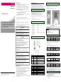
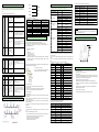
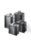
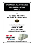
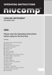
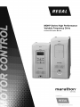
DATA SHEET Safety Precautions INSTRUCTIONS TO USERS ► Safety Precautions are for using the product safe and correct in order to prevent the accidents and danger, so please go by them. Profibus Option MDLV- HP Series ► The precautions explained here only apply to the MDHP Profibus Option. For safety precautions on the Inverter system, refer to the MDHP User’s manual. ► The precautions are divided into 2 sections, ‘Warning’ and ‘Caution’. Each of the meanings is represented as follows. Warning Marathon Drives Caution If violated instructions, it can cause death, fatal injury or considerable loss of property. If violated instructions, it can cause a slight injury or slight loss of products ► The symbols indicated in products and datasheet mean as follows This symbol means pay attention because of danger of injury, fire or malfunction. This symbol means paying attention because of danger of electric shock. - When using MD equipment, thoroughly read this datasheet and associated manuals introduced in this datasheet. Also pay careful attention to safety and handle the module properly. - Store this datasheet in a safe place so that you can take it out and read it whenever necessary. ► Store this datasheet in a safe place so that you can take it out and read it whenever necessary. Always forward it to the end user. Warning ► Do not contact the terminals while the power is applied. It can cause electric shock and malfunction. ► Protect the product from being gone into by foreign metallic matter. Warning It can cause fire, electric shock and malfunction. ire, electric shock and malfunction. Caution 4. Option Installation Method Thank you for your selecting our Profibus-DP option. This instruction includes how to use the product and the instruction during handling. Your wrong handling of this product may cause damage and then it reduces the duration of the product. Therefore, please read this instruction carefully and then observes the instruction without fail. 4.1 How to install option to inverter 1) Power off. 2) Connect connector after isolating front cover from MDHP as shown in Figure below. 3) Fix by enclosed volt. 4) Power On and Check “Profibus” at parameter, “CNF 31: Option-1 Type”. 1. Summary 1.1 Introduction You can connect MDHP inverter to Profibus network using Profibus option. With Profibus option board built in, inverter control and monitoring by PLC sequence program or optional master module are available. As a number of inverters in connection operate through one communication line only, It reduces the installation cost compared with communication being unused. Furthermore, its simple wiring enables the reduction of installation time and easy maintenance and repair. 1.2 Construction of Product Profibus option, (1) 9-Pin Connector, Fixing Screw (M3), Manual 2. Product Specification 1.1. Basic Communication Specification of Profibus Option Device Type : Profibus DP Slave Auto Baud Rate Detect : Support Sync Mode : Support Freeze Mode : Support Max Input Length : 8 words Max Output Length : 8 words Max Data Length : 16 words Baud Rate Support : 9.6K, 19.2K, 93.75K, 187.5K, 500K, 1.5M, 3M, 6M, 12M Modular Station : Support Max Module :2 Caution ► Cut off the power when remove the option, it may cause electric shock or break down. NOTE 1) MDHP has 3 option connectors, they are located in front upper, lower and left side: Option at the Figure. 2) Profibus must be connected with Option 5. Profibus Parameter 5.1 Station Address Setting 3. Appearance and Name of Each Part Minimum Value ► Be sure to check the rated voltage and terminal arrangement for the Field Bus ID module and observe them correctly. 0 Max. Value Position on Keypad 125 No. 7 of COM Group ※ Station address is a peculiar value distinguishing each node in the Profibus Network, ④ It can cause fire, electric shock and malfunction. and therefore each different device cannot jointly possess the same value. Station address can be changed through Keypad manipulation. Default value set from the factory is 1. ► Tighten up the terminal screw firmly to defined torque when wiring. If the terminal screw looses, it can cause fire and electric shock. ► Do not install around inflammable substances. It can cause fire. ⑤ ①②③ ► Use in an environment that meets the general specifications contained 5.2 Number of Status Data Setting Determines the number of output data (Variable to be monitored out of the inverter variables) Minimum Value Para Status Num 0 Max. Value Position on Keypad 8 No. 30 of COM Group in this datasheet. 5.3 Number of Control Data Setting Determines the number of input data (Variable to be commanded from outside among the inverter variables) It can cause electrical shock, fire, erroneous operation and deterioration. ► Be sure that external load does not exceed the rating of output It can cause fire and erroneous operation. ► Do not use in the environment of direct vibration LED Display No. Name It can cause poisonous pollution or explosion. Precautions for use DATA_EX LED Always “On” when Profibus is Online status. ERROR LED “On” when error occurs in the option ③ CPU LED “On” when the option board is built in the inverter and power is supplied to the inverter ④ Communication connecting Terminal Terminal that communication ⑤ Inverter connecting Connector Terminal that connects it with inverter body Protective Ground Line M24 24V Output GND ► When using the product, use the inverter with grounded. For the method of GND, please refer to the instruction manual of inverter body. 3 RxD/TxD-P Send/Receive Data Plus 4 CTRL-P Control Signal for Repeater 5 DGND Signal GND 6 VP 5V for Terminating Resistance 7 P24 24V Output Plus 8 RxD/TxD-N Send/Receive Data Negative 9 CTRL-N Control Signal for Repeater ► Input/output signal or communication wire should be 100mm away from high voltage cable or power line. Profibus Para Status 1~8 Note) This product supports the signal Nos. 3,5,6,8 only. Position on Keypad 8 No. 50 of COM Group Minimum Value Max. Value 0h0000 0hFFFF Position on Keypad Nos. 31~38 of COM Group 5.5 Address of Input Data Setting Determines the address setting in the number of data to be input. Communication Line Connecting Terminal Pin No. Signal Description Shield ► Turn off when install or uninstall the option. with 0 Max. Value 5.4 Address of Output Data Setting Determines the address setting in the number of data to be output. ※ For further operation, please refer to ‘7. Troubleshooting’. 2 ► Use Mobile or Radio telegraph at 30cm away from the product. 04- 2015 it 1 ► Do not separating or remodeling the PCB of Option card. this datasheet is subjected to change without notice. connects ► This option card is for MDHP only. Don’t install it to any other device than MDHP. ► Be sure to connect inverter and option card exactly. For the method of connection, Please refer to “6. How to install option” in MDHP User’s Manual. Regal Australia constantly endeavors to improve our products so that information in Application ② It can cause electrical shock, fire and erroneous operation. ► When disposing, treat it as industrial waste. Para Ctrl Num ① It can cause electrical shock, fire and erroneous operation. ► Do not disassemble, repair or modify except A/S specialist. Minimum Value Figure 1. Exterior Appearance module. Para Ctrl 1~8 Minimum Value Max. Value 0h0000 0hFFFF Position on Keypad Nos. 51~58 of COM Group 5.6 I/O Data Send/Receive Output data set in the keypad of the inverter is transmitted to Profibus Master Module (Control Program of PLC or PC) through Profibus Option Module. On the contrary, the control data is transmitted from Profibus Master Module (Control Program of PLC or PC) to Profibus Option Module, which is sent from Profibus Option Module to the inverter. 6. Basic Feature When turning on the inverter power or when reset occurs; CPU LED flashes if power supply is in normal state. ERR LED is On if power supply is in abnormal state. Conduct configuration using the keypad. If the communication with the Master Station as configured, Profibus communication status DATA_EX LED is Off. 7. Unusual Operation and Measures 10.4 0h240 ~ 0h27F: Macro Grp Parameter Currently Configured 10. Communication Parameter +5V (6) 390Ω The status of device and network is displayed through three (3) LED (DATA_EX, ERR, CPU) lights located at the lower part of the Product. The current status can be checked through the display of LED. 7.1 DATA_EX LED Operation and Measures against Error LED Status Cause Help When Master fails to start communication Wrong wiring Connector of No master inside the current network Off Off-Line Station Error Address A-Line (3) 10.1 Map Structure of Whole Communication Parameter in European Style 220Ω Category B-Line (8) iS5 Series Compatible Common Category 390Ω GND (5) Parameter Registered Type Category 8.2 Max. Transmitting Distance Specification Master starts communication. Check for the wiring of pin number and terminating resistance of the connector. No master allotted or problem of master station. Check if the station address allotted to the Profibus-use option module of LS inverter is same as that designated by keypad in the tool configured, and it is only one in the network. Communication Speed(Kbps) Address Max. Segment Length Max. Extended Distance 9.60 1000 m / 3278 feet 10000 m / 32786 feet 19.20 1000 m / 3278 feet 10000 m / 32786 feet European Common Category Network Config. Problem. On On-Line Status Network, Station Address, Parameterization, Configuration are all in normal condition 0h0100~0h01FF Parameter registered on COM Grp 0h0200~0h023F Parameter registered on Usr Grp 0h0240~0h027F Parameter registered on Macro Grp 0h0280~0h02FF Reserved 0h0300~0h037F Inverter State (Read Only) Parameter 0h0380~0h03FF Inverter Control (Read/Write) Parameter 0h0400~0h0FFF Reserved 0h1000 MAK Grp 0h1100 DRV Grp BAS Grp 93.75 1000 m / 3278 feet 10000 m / 32786 feet 187.50 1000 m / 3278 feet 10000 m / 32786 feet 500.00 400 m / 1311 feet 4000 m / 13114 feet 1500.00 200 m / 655 feet 2000 m / 6557 feet 3000.00 100 m / 327 feet 1000 m / 3278 feet 6000.00 100 m / 327 feet 1000 m / 3278 feet 0h1200 12000.00 100 m / 327 feet 1000 m / 3278 feet 0h1300 ADV Grp 0h1400 CON Grp Off Flashin g with 1 sec. interval Status Power Supply Defect Normal Cause inverter power supply defect/ Defect of Contact between inverter and option 9.1 GSD Files (Electronic Data Sheets) This is the file including the information of inverter Profibus Option Module. This file is required in the Profibus Configuration Software. Be sure to use iS7-use GSD file. The relevant file can be downloaded from the homepage of LS Industrial Systems Co., Ltd. (http://www.regalaustralia.com.au). ► GSD File Name : LSIS0A6C.GSD 7.2 CPU LED Operation and Measures against Error LED KeyPad Parameter Category ► Version : 2.00 ► ICON File Name Stop Icon : LSIS_INV_S.DIB Run Icon : LSIS_INV_R.DIB Diagnostic Icon : LSIS_INV_D.DIB Help Check for the condition of inverter power supply. Check for error of inverter. Check for the contact between inverter and connector. ► It doesn’t support from Module = "9 Word Status Input Data” 0h58 to Module = "16 Word Status Input Data", and from Module = "9 Word Control Output Data" 0h68 to Module = "16 Word Control Output Data" 0h6F. You may attach LSIS0A6C.GSD to the folder where GSD file is stored in Master Configuration program, and attach ICON files to the ICON storage folder. Ex) In case it is Sycon used in XGT; Here, you may attach LSIS0A6C.GSD to GSD under the PROFIBUS folder, and then attach ICON files to BMP. Normal Operation 7.3 Error LED Operation and Measures against Error LED Off Flashin g with 1 sec. interval Flashin g with approx. 1 sec. interval Status Normal Inverter ~ option communic ation Error CONFIG ERROR Cause Help Normal Operation Communication between inverter and option is not available When On line status is arranged in the Master, if configurations of Master and Profibus option are different each other. Check for abnormal connection between option and inverter. ※ It flashes like CPU LED. Check if the config. info. of inverter set in Master corresponds with that inside the inverter. ※ Configured Data: Number of Status Data and Control Data. ※It flashes contrary to CPU LED. 8. Construction of System & Transmission Specification 8.1 Installation of Terminating Resistance and its Specification 9.2 User Parameter Setting You may set Profibus-use User Parameter including Cycon in Profibus Master. 1). Data Word Format Inverter data is word, which is sent divided into byte at the time of data transmission. At this time, whether transmitting to MSB-LSB or to LSB-MSB will be elected. Initial value is MSB-LSB. 2). Config Data Update Decide if forcing to set the number of inverter I/O data compulsorily by the Master, or generating the Configuration Error. Selection is to be made out of Disable and Enable. If Enable is selected, the set value of master is forced to be set in the inverter. At this time, the initial value is Disable. If the number of I/O data set in the inverter doesn’t corresponds with that set in the Master, Config Err occurs. This is the useful function when testing the communication with the inverter under Enable status. 9.3 Extended Diagnostic As the safety-related function, it generates diagnostic in the master when trip occurs in inverter or option. There are 5 defined extended diagnostics as follows: 1). Cannot connect between Main and Option: Defect of communication between inverter and option 2). Inverter H/W Diag Trip: When hardware diagnostic trip occurs in the inverter 3). Inverter Latch Type Trip: When trip in latch type occurs 4). Inverter Level Type Trip: When trip in level type occurs 5). Inverter Warning: When warning occurs Parameter 0h0240 Macro Grp. Code 1 Parameter value registered on U&M>MC->1 0h0241 Macro Grp. Code 2 Parameter value registered on U&M>MC->2 0h0242 Macro Grp. Code 3 Parameter value registered on U&M>MC->3 0h0243 Macro Grp. Code 4 Parameter value registered on U&M>MC->4 . . . 0h024C Macro Grp. Code 61 Parameter value registered on U&M>MC->61 0h024D Macro Grp. Code 62 Parameter value registered on U&M>MC->62 0h024E Macro Grp. Code 63 Parameter value registered on U&M>MC->63 0h024F Macro Grp. Code 64 0h0000~0h00FF 9. Environment Configuration & Other Functions Check if it exceeds the max. length of the segment. Check if 32 or more stations including repeater are connected with the segment. Check if 126 or more stations including repeater are connected with the network. Type of Parameter Address 0h1500 IN Grp 0h1600 OUT Grp 0h1700 COM Grp 0h1800 APP Grp 0h1900 AUT Grp 0h1A00 APO Grp 0h1B00 PRT Grp 0h1C00 M2 Grp Parameter value registered on U&M>MC->64 * In case of accessing the code not smaller than the size of macro currently configured, return to “Illegal data address” Error Code “02”. Note 1) For further inverter address and function, please refer to ‘Communication Function’, Section 11 in MDHP Main Body Manual. 11. Product Size ※ Option Size 22.5mm 10.2 Parameter Group for Periodical Transmission Parameter Group that can make Communication using the Address registered in Communication Function Group (COM) 0h100 ~ 0h107: Inverter Status Parameter registered on Status Para # of KeyPad Parameter COM Group 0h110 ~ 0h117: Inverter Control Parameter registered on Control Para # of KeyPad Parameter COM Group All other categories (0h108 ~ 0h10F, 0h117 ~ 0h1FF) are invalid addresses. Address Parameter R/W Value Allotted by Bit 0h0100 Status Parameter #1 R Parameter value registered on COM-31 0h0101 Status Parameter #2 R Parameter value registered on COM-32 0h0102 Status Parameter #3 R Parameter value registered on COM-33 0h0103 Status Parameter #4 R Parameter value registered on COM-34 0h0104 Status Parameter #5 R Parameter value registered on COM-35 0h0105 Status Parameter #6 R Parameter value registered on COM-36 0h0106 Status Parameter #7 R Parameter value registered on COM-37 0h0107 Status Parameter #8 R Parameter value registered on COM-38 0h108~0h10F Invalid address 0h0110 Control Parameter #1 R/W Parameter value registered on COM-51 0h0111 Control Parameter #2 R/W Parameter value registered on COM-52 0h0112 Control Parameter #3 R/W Parameter value registered on COM-53 0h0113 Control Parameter #4 R/W Parameter value registered on COM-54 0h0114 Control Parameter #5 R/W Parameter value registered on COM-55 Category not used 0h0115 Control Parameter #6 R/W Parameter value registered on COM-56 0h0116 Control Parameter #7 R/W Parameter value registered on COM-57 0h0117 Control Parameter #8 R/W Parameter value registered on COM-58 0h118~0h1FF Invalid address Category not used 10.3 Parameter Group for User & Macro Grp Transmission 0h200 ~ 0h23F: User Grp Parameter Currently Registered Address Parameter Value Allotted by Bit 0h0200 User Grp. Code 1 Parameter value registered on U&M>USR->1 0h0201 User Grp. Code 2 Parameter value registered on U&M>USR->2 0h0202 User Grp. Code 3 Parameter value registered on U&M>USR->3 0h0203 User Grp. Code 4 Parameter value registered on U&M>USR->4 . . . 0h023C User Grp. Code 61 Parameter value registered on U&M>USR->61 0h023D User Grp. Code 62 Parameter value registered on U&M>USR->62 0h023E User Grp. Code 63 Parameter value registered on U&M>USR->63 0h023F User Grp. Code 64 Parameter value registered on U&M>USR->64 * In case of accessing the code not registered on User Grp, return to “Illegal data address” Error Code “02”. Value Allotted by Bit 69mm 93mm 12. Warranty 12.1 Warranty Service Period Warranty period is 12 months from date of sale 12.2 Range of Warranty If the defective part has been identified under normal and proper use within the guarantee term, contact your local authorized MD distributor or MD service center. But the guarantee will not apply in the following cases, even if the guarantee term has not expired. Damage was caused by misuse, negligence or accident. Damage was caused by abnormal voltage and peripheral devices’ malfunction (failure). Damage was caused by improper repair or altering by other than MD authorized distributor or service center. Damage was caused by an earthquake, fire, flooding, lightning, or other natural calamities. When MD nameplate is not attached. When the warranty period has expired. 12.3 Please considerate it’s stability when apply this option with the system. IOM_MarathonDrive_MDHP_Profibus-DPOptionManual_ 0415