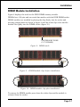
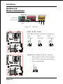
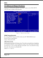
1
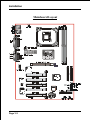
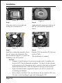
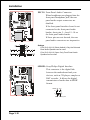
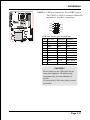
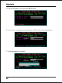
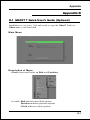
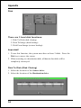
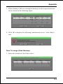
User’s Manual An Intel Soc ket 478 Pr ocessor Based Sock Processor Mainboard (400/533MHz) Suppor ts PC1600/ 2100 /2700 Memor y Modules Supports PC1600/2100 2100/2700 Memory (DDR Memor y) TRADEMARK All products and company names are trademarks or registered trademarks of their respective holders. These specifications are subject to change without notice. $ "2- Manual Revision 1.1 October 08, 2002 Table of Contents Page Section 1 Introduction Components Checklist .............................................. 1-1 Overview System Overview ....................................................... 1-2 Chipset Components ................................................. 1-3 Intel Pentium 4 Processors ...................................... 1-4 Accelerated Graphics Port ....................................... 1-6 Utlra ATA66/100 ....................................................... 1-6 Hardware Monitoring ................................................ 1-6 Bandiwdth Overview .................................................. 1-7 Mainboard Form-Factor ............................................ 1-8 I/O Shield Connector ................................................ 1-9 Power-On/Off (Remote) .......................................... 1-9 System Block Diagram ............................................. 1-10 Section 2 Features Mainboard Features ................................................... 2-1 Section 3 Installation Mainboard Detailed Layout ...................................... 3-2 Easy Installation Procedure CPU Installation ........................................................ 3-3 Jumper Settings ......................................................... 3-5 System Memory Configuration ................................ 3-6 Device Connectors .................................................... 3-8 External Modem Ring-in Power ON and Keyboard Power ON Function (KBPO) ................... 3-13 STR (Suspend To RAM) Function .......................... 3-14 845PE platform AGP Card 3.3V Protection ........... 3-15 Section 4 Award BIOS Setup Main Menu ................................................................ 4-1 Standard CMOS Setup ............................................... 4-2 Advanced BIOS Features ........................................... 4-3 Advanced Chipset Features ....................................... 4- 8 Integrated Peripherals ............................................... 4-11 Power Management Setup ........................................ 4-17 PNP/PCI Configuration Setup .................................. 4-22 PC Health Status ........................................................ 4-25 Frequency/Voltage Control ....................................... 4-27 Defaults Menu ........................................................... 4-30 Supervisor/User Password Setting ........................... 4-31 Exit Selecting ............................................................ 4-32 Section 5 Driver Installation Easy Driver Installation ............................................. 5-1 ALC650 Configuration Setup (6 Channel) ............... 5-2 Appendix Appendix B Avance Media Player Users Guide .......................... A-1 Appendix B Update Your System BIOS ........................................ B-1 Appendix C EEPROM BOIS Remover ......................................... C-1 Appendix D GHOST 7 Quick Users Guide (Optional) ............... D-1 Introduction Section 1 INTRODUCTION Package Contents Contents Optional Item A. (1) Mainboard F. (1) COM2 port cable B. (1) Users manual G. (1) USB2.0 Cable C. (1) Floppy ribbon cable H. (1) Bluetooth Module D. (1) ATA-66/100 Hard drive ribbon I. (1) SPD650 card cable E. (1) Driver and utility C USERS MANUAL B G E or A F D H I Page 1-1 Introduction System Overview This board is designed with Intel® 845PE chipset. The Intel® 845PE chipset includes MCH(FW82845PE), ICH4(FW82801DB) and FWH three chips. The Intel® 845PE chipset is designed for Intels FC-PGA2 socket 478 package architecture and support the 4X capability of the AGP 2.0 Interface Specification. A new chipset component interconnect, the hub interface, is designed into the Intel® 845PE chipset to provide more efficient communication between chipset components. Support of AGP 4X, 266/333MHz DDR SDRAM and the hub interface provides a balanced system architecture for the Pentium® 4 in the Socket 478 architecture processor minimizing bottlenecks and increasing system performance. By increasing memory bandwidth to 2.128GB/s through the use of AGP 4X, the Intel® 845PE chipset will deliver the data throughput necessary to take advantage of the high performance provided by the powerful Pentium® 4 in the Socket 478 architecture processor. The Intel® 845PE chipset architecture removes the requirement for the ISA expansion bus that was traditionally integrated into the I/O subsystem of Intel chipsets. This removes many of the conflicts experienced when installing hardware and drivers into legacy ISA systems. The elimination of ISA will provide true plug-and play for the Intel® 845PE platform. Intel® 845PE chipset contains three core components: the Memory Controller Hub (MCH), the I/O Controller Hub (ICH4) and the Firmware Hub (FWH). The MCH integrates the data transfer rate of 400/533MHz, Pentium® 4 processor bus controller, AGP 2.0 controller, 266/333MHz DDR SDRAM controller and a highspeed hub interface for communication with the ICH4. The ICH4 integrates an UltraATA/66/100 controller, USB host controller, LPC interface controller, FWH interface controller, PCI interface controller, and a hub interface for communication with the MCH. The Intel® 845PE chipset will provide the data buffering and interface arbitration required to ensure that system interfaces operate efficiently and provide the system bandwidth necessary to obtain peak performance the Pentium® 4 in the Socket 478 architecture. Page 1-2 Introduction Chipset Components The Intel® 845PE chipset consists of the Memory Controller Hub (MCH), the I/O Controller Hub (ICH4) and the Firmware Hub (FWH). ! Memory Controller Hub (MCH) The MCH provides the interconnect between the DDR SDRAM and the system logic. It integrates: - Support for single processor with a data transfer rate of 400/533MHz. - 200/266/333MHz DDR SDRAM interface supporting 2GB of DDR SDRAM. - 4X 1.5V AGP interface (Only support 1.5V on AGP interface). - Downstream hub link for access to the ICH4. ! I/O Controller Hub (ICH4) The I/O controller Hub provides the I/O subsystem with access to the rest of the system. Additionally, it integrates may I/O functions. The ICH4 integrates: - Upstream hub link for access to the MCH - 2 Channel Ultra ATA/33/66/100 Bus Master IDE controller - USB controller - SMBus controller - FWH interface - LPC interface - PCI 2.2 interface - Integrated System Management Controller - Integrated LAN Controller ! Firmware Hub (FWH) The FWH component is a key element to enabling a new security and manageability infrastructure for the PC platform. The device operates under the FWH interface and protocol. The hardware features of this device include a unique a Random Number Generator (RNG), register-based locking, and hardwarebased locking. Page 1-3 Introduction Intel Pentium 4 processors Formally known as the Willamette, the PentiumTM 4 is the next PEneration IA-32 processor from Intel. This next generation design is based upon a new microarchitecture that brings higher clock speeds and performance than previous processors could deliver. Among other advanced features the Pentium 4 offers Streaming SIMD extensions 2, Advanced Dynamic Execution, Hyper Pipelined Technology, and a data transfer rate of 400/533MHz system bus. Streaming SIMD Extensions 2 Building upon the foundations of core features of their previous line of processors the Pentium 4, this new version introduces Streaming SIMD Extensions 2 technology commonly referred to as SSE2. But what does this mean? SIMD stands for Single Instruction Multiple Data. Usually, processors process one data element in one instruction, called Single Instruction Single Data, or SISD. In contrast, with Single Instruction Single Data (SISD), SIMD has the ability to process more than one piece of data element during one instruction. This technology is useful for 3D graphics applications that handle considerable amounts of floating-point numbers. With SIMD applications such as 3D graphics will be able to processor more data per instruction when equates to better performance. This technology adds 144 new instructions to the CPU core that can be used in a wide variety of applications. Software programmers can for example, take advantage of these new instructions and write more optimized code that take advantage of newer SIMD double-precision floating-point, integer, and cache ability instructions. In theory this will enable better next generation services such as Interactive Digital TV to be produced. Advanced Dynamic Execution Advanced Dynamic Execution describes the improved implementation and abilities over the older P6 processor lines out-of-order decoupled super scalar execution. Dynamic execution allows instructions to the processor to be executed without the need to do so in order. The ability to do this can add a significant performance increase versus ordered execution. Page 1-4 Introduction Hyper Pipelined Technology & 400/533MHz System Bus Hyper Pipelined Technology doubles the pipeline depth the Pentium 4 delivers to 20 stages. This significantly increases the performance and frequency capabilities. Pentium 4 also introduces a 400/533MHz system bus as opposed to the 100 and 133MHz bus seen in previous Pentium III processors. This allows 3.2Gbytes per second of throughput while the Pentium III had a limited 1.06Gbyte/s throughput. Willamette will reportedly be introduced in the 0.18-micron using aluminum. Hyper-Threading Technology Hyper-Threading Technology is a new features in the IA-32 Intel Architecture that provides a performance boost for future Intel-32 processors based on the Intel NetBurstTM micro architecture. This technology enables a single processor to run two separate threads simultaneously, this arrangement looks like two processors. Hyper-Threading Technology makes a single physical processor appear as multiple logical processors, there is one copy of the architecture state for each logical processor, and the logical processor share a single set of physical execution resources. From a software or architecture perspective, this means operating systems and user programs can schedule processors or threads to logical processors as they would on conventional physical processors in a multi-processor system. From a micro architecture perspective , this means that instructions form logical processors will persist and execute simultaneously on shared execution resources. For more information about all the new features the Pentium 4 delivers check out the Intel website at http://www.intel.com Page 1-5 Introduction Accelerated Graphics Port (AGP or A.G.P.) Typically, 3D graphics rendering requires a tremendous amount of memory, and demands ever increasing throughput speed as well. As 3D products for the personal computer become more and more popular, these demands will only increase. This will cause a rise in costs for both end users and manufacturers. Lowering these costs as well as improving performance is the primary motivation behind AGP. By providing a massive increase in the bandwidth available between the video card and the processor, it will assist in relieving some of these pressures for quite sometime. The board provides the AGP 2.0 interface. The AGP Interface Specification revision 2.0 enhances the functionality of the original AGP Interface Specification (revision 1.0) by allowing 4X data transfers (4 data samples per clock) and 1.5 volt (power supply) operation. The AGP 2.0 interface, along with SDRAM memory technology, allows graphics controllers to access main memory at over 1GB/s. In order to match the 4X AGP Card. The board used the Universal AGP connector. (1.5 volt AGP Card supports only). Ultra ATA/66/100 The ICH4 provides two channel Ultra ATA/66/100 Bus Master IDE controllers, that support Ultra ATA/66/100 protocols, perfect for such demanding applications as real-time video, multimedia, and high performance operating system. A new IDE cable is required for Ultra ATA/66/100. This cable is an 80 conductor cable; however the connectors are, of course, backwards compatible with ATA/33. Hardware Monitoring Hardware monitoring allows you to monitor various aspects of your systems operations and status. The features include CPU temperature, voltage and RPM of fan. Page 1-6 Introduction Bandwidth Overview Table 1 provides a summary of the bandwidth requirements for the Intel® 845PE chipset. Interface Clock Speed (MHz) Samples Per Clock (Mega-samples/s) Data Rate Data Width (Bytes) Bandwidth (MB/s) CPU Bus 100/133 4 400/533 8 3200/4264 DDR SDRAM 100/133/166 2 200/266/333 8 1600/2128/2664 AGP 2.0 66.6 4 266 4 1066 Hub Link 66.6 4 266 1 266 PCI 2.2 33.3 1 33.3 4 133 Table 1: Intel® 845PE platform Bandwidth Summary Page 1-7 Introduction Mainboard Form-Factor The board is designed with ATX form factor - the latest industry standard of chassis. The ATX form factor is essentially a Baby-AT baseboard rotated 90 degrees within the chassis enclosure and a new mounting configuration for the power supply. With these changes the processor is relocated away from the expansion slots, allowing them all to hold full length add-in cards. ATX defines a double height aperture to the rear of the chassis which can be used to host a wide range of onboard I/O. Only the size and position of this aperture is defined, allowing PC manufacturers to add new I/O features (e.g.; TV input, TV output, joystick, modem, LAN, audio, etc.) to systems. This will help systems integrators differentiate their products in the marketplace, and better meet your needs. By integrating more I/O down onto the board and better positioning the hard drive and floppy connectors material cost of cables and add-in cards is reduced. By reducing the number of cables and components in the system, manufacturing time and inventory holding costs are reduced and reliability will increase. By using an optimized power supply, it's possible to reduce cooling costs and lower acoustical noise. An ATX power supply, which has a sidemounted fan, allows direct cooling of the processor and add-in cards making a secondary fan or active heatsink unnecessary in most system applications. Expandable I/O AT X Power Supply PCI slots Single chassis fan for system ATX 12V power connector AGP slot ATX power connector Floppy / IDE connectors 3 1/2" Bay 5 1/4" Bay Figure 2: Summary of ATX chassis features Page 1-8 CPU Introduction I/O Shield Connector The board is equipped with an I/O back panel. Please use the appropriate I/O shield (figure 3). RJ-45 LAN (Optional) Joystick/Midi Port Parallel Port PS/2 Mouse PS/2 Keyboard USB2.0 ports COM1 Line-out Line-in Mic-in Figure 3: I/O back panel layout Power-On/Off (Remote) The board has a single 20-pin and 4-pin connector for ATX or ATX12V power supplies (Figure 4). For ATX or ATX12V power supplies that support the Remote On/Off feature, this should be connected to the mainboard front panel PW_ON connector for the computer power On/Off button. The board has been designed with Soft Off" function. You can turn off the system two ways: pressing the front panel power On/Off button, using the "Soft Off" function (incorporated in the mainboards onboard circuit controller) that can be controlled by an operating system such as Windows®ME/2000/98/95. Note: For maintaining the DDR SDRAM power during STR (ACPI S3) function, it is strongly recommend to use ATX or ATX12V power supplies that have a +5VSB current of (>=) 1A (1000mA). Please check the 5VSBs specification that has been printed on the ATX or ATX12V power supplys outer case. Note: The board requires a minimum of 250 Watt ATX or ATX 12V power supply to operate. Your system configuration (amount of memory, add-in cards, peripherals, etc.) may exceed the minimum power requirement but to ensure that adequate power is provided, use a 300 Watt (or greater) ATX or ATX 12V power supply. 12V 4-pin 20-pin J3 Case (chassis) Power ON/OFF button (J 3) Figure 4: Simple ATX power ON/OFF controller Page 1-9 Introduction System Block Diagram Pentium 4 Processor 478 pin Package 100/133MHz 4X (1.5V only) 66MHz DDR SDRAM 200/266/333MHz MCH (Memory Controller Hub) 1,- 1,- HDD PCI Slots ICH4 (I/O Controller Hub) AC'97 Audio USB 1,2 USB 3,4 USB 5,6 Serial Port 1 serial Port 2 LPT Port PS/2 Mouse PS/2 Keyboard Game IR LPC I/O Winbond 83627HF FWH (Firm Ware Hub) Flash memory Figure 5: System Block Diagram Page 1-10 .A=JKHAI Section 2 FEATURES Mainboard Features: ! PROCESSOR ® - Intel Pentium 4 Processor with FC-PGA2 socket 478 package: Operating at 1.4 ~ 2.8GHz - Supports Hyper-Threading Technology Enabling the functionality of Hyper-Threading Technology for your computer system requires ALL of the following platform Components: " CPU: ® ® An Intel Pentium 4 Processor with HT Technology. ® " Chipset: An Intel Chipset that supports HT Technology. ! "BIOS: A BIOS that supports HT Technology and has it enabled. "OS: An operating system that supports HT Technology. CHIPSET - Intel 82845PE Chipset (82845PE + ICH4) ! Front Side Bus - 400/533MHz ! DRAM MODULE - 184pin DDR DIMM x 2 for PC1600/2100/2700 Memory - DRAM Size: 64MB to 2GB ! EXPANSION SLOT - PCI x 5 - 4X AGP x 1 (1.5V only) Page 2-1 .A=JKHAI ! ONBOARD I/O - Winbond 83627HF-AW LPC I/O integrated with K/B , Mouse, FDD, Parallel and Serial, Fast IR and Power-ON controllers ! ONBOARD PCI / IDE Intel 82801DB/ICH4 Controller - PCI Rev. 2.2 Compliant - ACPI Compliant Power Management - PCI Bus IDE Port with PIO /Ultra DMA-33/66/100 x 2 (Up to 4 Devices) ! Onboard LAN (Optional) - Integrate 10/100 Mp fast Eyhernet controller in VIA VT6105 LAN chipset by RJ-45 connector ! I/O CONNECTOR - PS/2 Mouse and PS/2 style Keyboard - COM1, COM2 by extra RS232 cable, Printer, Audio-in/out, MIC & Game port connectors ! USB - Supports USB2.0 specification - USB connector x 6 (4 for Optional) - USB3 can support bluetooth module ! Built-in AC97 Digital Audio ( By Realtek ALC650) - Compliant with AC97 2.2 Specification - 6 channel slot selectable DAC output for multi-channel applications - Supports digital SPDIF - Supports 2 general purpose I/O pins ! BIOS - Award Plug & Play BIOS Page 2-2 .A=JKHAI ! EXTENDED FUNCTION - Supports Hardware Monitoring Function by W83627HF-AW - Supports exclusive KBPO (Keyboard Power ON) Function - Supports STR (Suspend To RAM) power saving Function - Supports Wake-On-LAN Function - Supports CPU Clock and Ratio Settings via BIOS - Supports CPU Vcore, AGP and memory Voltage Settings via BIOS - Supports Magic Health and Easy Boot Function - Supports Asynchronous Transfer Mode between PCI & FSB - Supports Programmable AGP/PCI clock output frequency with 1MHz increment - Supports AGP 1.5V Protection ! FORM FACTOR - 305mm x 220mm ATX Size Page 2-3 .A=JKHAI Page Left Blank Page 2-4 Installation Section 3 INSTALLATION Page 3-1 Installation Mainboard Layout Page 3-2 Installation Easy Installation Procedure The following must be completed before powering on your new system: 3-1. 3-2. CPU Installation Jumper Settings 3-3. 3-4. 3-5. System Memory Configuration Device Connectors External Modem Ring-in Power ON and Keyboard Power ON Functions (KBPO) STR Function 845PE Platform AGP Card 4X/1.5V Protection 3-6. 3-7. Section 3-1 CPU Installation Figure 2 Figure 1 Pin 1 Step 1 Step 2 Open the socket by raising the actuation lever. Align pin 1 on the CPU with pin 1 on the CPU socket as shown in the illustration above. The CPU is keyed to prevent incorrect insertion. Dont force the processor into the socket. If it does not go in easily, check for misorientation and reinsert the CPU. Make sure the processor is fully inserted into the socket. Page 3-3 Installation Figure 3 Figure 4 Step 3 Step 4 Close the socket by lowering and locking the actuation lever. Apply thermal compound to the top of the CPU and install the heatsink as shown. Figure 5 Step 5 Figure 6 Step 6 Install the cooling fan assembly. Press Plug the CPU fan into the CPU fan conthe two clips in the direction of the nector (FAN1). arrows shown in Figure 5 to secure the The installation is complete. assembly to the CPU socket. NOTES: Damage to Intel PentiumTM 4 processors might result if installed with incorrect CPU fan and heatsink assemblies. Use Intels design thermal solution shown in the illustrations above: an active heatsink; an extruded aluminum heatsink base; and a fan attached to the top on the fin array. Apply heatsink thermal compound or paste to the CPU to avoid CPU overheating and damage. In accordance with Intel Corp. specifications, do not install a CPU over 50 times to avoid bending the pins and damaging the CPU. Page 3-4 Installation Section 3-2 Jumper Settings JBAT1 CMOS Clear 1-2: Normal (Default) 2-3: Clear CMOS Page 3-5 Installation Section 3-3 System Memory Configuration Memory Layout The mainboard accommodates two PC1600/PC2100/2700 184-pin DIMMs (Dual In-line Memory Modules): Supports up to 2.0GB of 200/266/333MHz DDR SDRAM. Supports up to 2 DDR DIMMs (refer to Table 1). Supports DDR 200/266/333 unregistered 184-pin non-ECC DDR SDRAM DIMMs. Supports configurations defined in the JEDEC DDR DIMM specification NOTE:The mainboard does not support double-sided x 16 DDR DIMMs. Use DDR SDRAM (Double-Data-Rate Synchronous DRAM) modules only. Figure 7 and Table 1 show several possible memory configurations. <Figure 7> <Table 1> Total Me mory DDR DIMM 1 Bank 0/1 DDR DIMM 2 Bank 2/3 DDR DIMM 1 (Bank 0/1) DDR Synchronous DRAM DDR DIMM 2 (Bank 2/3) = 1GB Maximum DDR SDRAM* 64MB, 128MB, 256MB, 512MB, 1GB* X 1 None = 2GB Maximum DDR SDRAM* 64MB, 128MB, 256MB, 512MB, 1GB* X 1 DDR SDRAM* 64MB, 128MB, 256MB, 512MB, 1GB* X 1 * DDR SDRAM supports 64, 128, 256, 512MB and 1GB DIMM modules using 512Mb technology. NOTES: _ Using non-compliant memory with higher bus speeds (overclocking) may severely compromise the integrity of the system. Page 3-6 Installation DIMM Module Installation Figure 8 displays the notch on the DDR DIMM memory module. DIMMs have 184 pins and one notch that matches with the DDR DIMM socket. DIMM modules are installed by placing the chip firmly into the socket and pressing straight down as shown in figure 9 until the white clips close and the module fits tightly into the DIMM socket (figure 10). CENTER KEY ZONE (2.5 V DRAM) Figure 8 - DIMM notch Figure 9 - DIMM module clips before installation Figure 10 - DIMM module clip after installation To remove the DIMM module press down the white clips and the module is released from the socket. Page 3-7 Installation Section 3-4 Device Connectors RJ-45 LAN (Optional) Joystick/Midi Port Parallel Port PS/2 Mouse PS/2 Keyboard USB2.0 ports COM1 Line-out Line-in Mic-in Figure 11 - I/O Ports FAN1 / FAN2 / FAN3: CPU/Power/Chassis Fan Power Connectors FAN1 FAN2: Power Fan GND +12V NC GND +12V Rotation FAN1: CPU Fan FAN3: Chassis Fan GND +12V Rotation FAN2 FAN3 WOL1:WOL (Wake On LAN) Connector Reserved for an NIC (Network Interface Card) to wake the system from power saving mode. PME GND +5V Standby Page 3-8 Installation IDE1: Ultra DMA-66/100 Primary IDE Connector (Blue) IDE2: Ultra DMA-66/100 Secondary IDE Connector (Blue) FLOPPY1: Floppy Controller Connector (Black) ATX1: ATX Power Connector (20-pin power connector) ATX2 COM2 ATX1 ATX2: ATX12V Power Connector (12V 4-pin power connector) Note: The board requires a minimum of 250 Watt ATX or ATX 12V power supply to operate. Your system configuration (amount of memory, add-in cards, peripherals, etc.) may exceed the minimum power requirement but to ensure that adequate power is provided, use a 300 Watt (or greater) ATX or ATX 12V power supply. COM2:RS232 COM2 Connector CDIN1: CD Audio_IN Connector CD_IN_Right CD_Reference 1 CD_IN_Left AUXIN1: Auxiliary Line_IN Connector AUX_IN_Right CDIN1 AUXIN1 GND 1 AUX_IN_Left Page 3-9 Installation FPCN1: Front Panel Audio Connector When headphones are plugged into the front panel headphone jack, the rear panel audio output connectors are disabled. If the front panel interface board is not connected to the front panel audio header, short pins 5 - 6 and 9 -10 on the front panel audio header. If these pins are not shorted, the rear panel audio connectors are inoperative. Settings Pins (5-6) & (9-10) Short (default): Only the Onboard Rear Audio Speaker can be used. Pins (5-6) & (9-10) Open: Only Front Panel Audio Speaker can be used. SPDIF1: Sony/Philips Digital Interface This connector is the digital link between the motherboard and your devices, such as CD player, sampler or DAT recorder. It allows the digital transmission of audio data in SPDIF format. SPDIF_IN VCC 5 1 6 2 NC GND SPDIF_OUT Page 3-10 Installation USB2/3: USB port header for four USB2.0 ports. The USB3 is used to connect bluetooth module for wireless connection. VCC GND -Data +Data +Data USB2 -Data GND VCC ' USB port header pin descriptions USB3 PIN# Wire color Signal Name Comment 1 Red Vcc Cable Power 2 Black Ground Case Ground 3 White -Data Data 4 Black Ground Cable Ground 5 Green +Data Data 6 Green +Data Data 7 Black Ground Cable Ground 8 White -Data Data 9 Black Ground Case Ground 10 Red Vcc Cable Power CAUTION ! Please make sure the USB cable has the same pin assignment. The different pin assignment may be caused damage of system. If you need the USB cable, please contact our retailer. Page 3-11 Installation ! Power On/Off This is connected to the power button on the case. Using the Soft-Off by Pwr-BTTN feature, you can choose either Instant Off (turns system off immediately), or 4 sec delay (push the button for 4 seconds before the system turns off). When the system is in 4 sec delay mode, suspend mode is enabled by pushing the button momentarily. ! Turbo LED indicator J3 ! IDE LED indicator LED on when onboard PCI IDE Hard disks are being accessed. ! IR Connector 1. VCC 2. CIRRX 3. IRRX J2 4. GND 5. IRTX ! KeyLock Keyboard lock switch & power LED connector 1. Power LED(+) 4. KeyLock 2. N/C 5. GND * The power LED lights when the 3. GND system is powered on and blinks in SLEEP Mode or STR Mode. ! Speaker Connect to the systems speaker for beeping 1. Speaker 3. GND 2. N/C 4. VCC ! Reset Closed to restart system. Page 3-12 Installation Section 3-5 External Modem Ring Power ON and Keyboard Power ON Functions (KBPO) Modem Ring Power ON Function The I/O chipset provides the two serial ports with the External Modem Ring-in Power ON function. Once you connect an external modem to COM1 or COM2, the mainboard enables you to turn on the system through remote and host dial-up control. Keyboard Power ON Function The mainboard features a keyboard power on function that enables you to turn on the power supply using a keypress. Follow these instructions to enable the Keyboard Power ON function . Step : Use the Keyboard Power ON function (KBPO) to turn on the system by using a key press, password, or hot key combination etc. as set in the BIOS Power Management Setup menu (refer to the BIOS Power Management Setup for details). The BIOS default setting is keyboard Hot key (<Ctrl> + <F1>). To power off the system, use the soft-OFF function under Windows 2000/98/ 95 (refer to Windows online help). NOTES: Intel ATX version 2.0 specification recommends you use a power supply that supplies >=1.0 A in 5.0 VSB. However, this mainboard supports a 5.0 VSB standby power supply > = 0.1A (100mA). We recommend you use the power supply with 1.0 A in 5.0 VSB, which supports PCI 2.2 specification for remote power-on and wake-up functions. Page 3-13 Installation 3-6 STR (Suspend To RAM) Function This mainboard supports the STR (Suspend To RAM) power management scheme by maintaining the appropriate power states in the DDR SDRAM interface signals. The power source to the DDR SDRAM must be kept active during STR (ACPI S3). Advanced Configuration Power Interface (ACPI) provides many Energy Saving Features for operating systems that support Instant ON and QuickStartTM function. 1. Use the STR functionality to save system power, you are recommended to confirm the following requirements: a. Install ACPI qualified add-on cards (such as AGP, LAN, and modem cards). b. In BIOS under Power Management Setup (refer to Section 4), select ACPI Suspend Type: S3(STR) and USB Wake-Up From S3: Enabled (if you have a USB mouse or keyboard device). c. Install Windows® XP/2000/ME/98SE. d. Restart the system. e. Open the Control Panel Power Management application, and click the Advanced tab. In the Power buttons section, select Stand By from the drop-down lists. 2. To enable the STR function, click the START button and choose Shut Down. In the Shut Down Windows dialog box, select the Stand By option to enter STR mode. The following lists the differences between STR power saving mode and Green (or Suspend) mode: a. STR is the most advanced Power Management mode. b. STR cuts all the power supplied to peripherals except to memory - max. power saving. c. STR saves and keeps all on-screen data including any executed applications to DDR SDRAM. d. In STR mode, you must push the power button (connected to the onboard J3 pin), click your USB mouse buttons, or press your USB keyboard keys to wake up your system to the last display. NOTE: Clicking your PS/2 mouse or pressing a PS/2 keyboard key does not wake the system from STR mode. Page 3-14 Installation 3-7 845PE Platform AGP Card 3.3V Protection The Intel® 845PE chipset supports 1.5 volt AGP graphics cards only. Using a 3.3 volt AGP card in an Intel® 845PE chipset-based board might damage the chipset on an 845PE-equipped mainboard. However, this mainboard features a protection function that prevents the system from powering on when a 3.3V AGP card is inadvertently inserted into the AGP slot. If this happens, we recommend you to follow these steps: Step 1: Remove the 3.3V AGP card from the AGP slot. Step 2: Unplug the ATX/ATX12V power cable. Step 3: Insert a 1.5V AGP card into the AGP slot. Step 4: Wait for 5 ~ 7 seconds and then plug in the ATX/ATX12V power cord again (or turn on the ATX/ATX12V power switch) to turn on your system. Note: There should be an interval of 5 ~ 7 seconds between unplugging and plugging in the power cord, or turning the ATX/ATX12V power supply on and off. Page 3-15 Installation Page Left Blank Page 3-16 BIOS Section 4 AWARD BIOS SETUP Main Menu Awards ROM BIOS provides a built-in Setup program which allows user to modify the basic system configuration and hardware parameters. The modified data is stored in a battery-backed CMOS, so that data will be retained even when the power is turned off. In general, the information saved in the CMOS RAM will stay unchanged unless there is a configuration change in the system, such as hard drive replacement or a device is added. It is possible for the CMOS battery to fail causing CMOS data loss. If this happens you will need install a new CMOS battery and reconfigure your BIOS settings. To enter the Setup Program : Power on the computer and press the <Del> key during the POST (Power On Self Test). The BIOS CMOS SETUP UTILITY opens. Figure 1: CMOS Setup Utility Page 4-1 BIOS The main menu displays all the major selection items. Select the item you need to reconfigure. The selection is made by moving the cursor (press any direction (arrow key ) to the item and pressing the Enter key. An on-line help message is displayed at the bottom of the screen as the cursor is moved to various items which provides a better understanding of each function. When a selection is made, the menu of the selected item will appear so that the user can modify associated configuration parameters. 4-1 Standard CMOS Setup Choose STANDARD CMOS FEATURES in the CMOS SETUP UTILITY Menu (Figure 2). Standard CMOS Features Setup allows the user to configure system settings such as the current date and time, type of hard disk drive installed, floppy drive type, and display type. Memory size is auto-detected by the BIOS and displayed for your reference. When a field is highlighted (use direction keys to move the cursor and the <Enter> key to select), the entries in the field can be changed by pressing the <PgDn> or the <PgUp> key. Figure 2: Standard CMOS Setup Page 4-2 BIOS Notes: _ If the hard disk Primary Master/Slave and Secondary Master/Slave are set to Auto, then the hard disk size and model will be auto-detected. _ The Halt On: field is used to determine when to halt the system by the BIOS if an error occurs. _ Floppy 3 Mode support is a mode used to support a special 3.5-inch drive used in Japan. This is a 3.5-inch disk that stores 1.2 MB. The default setting for this is disabled. 4-2 Advanced BIOS Features Selecting the ADVANCED BIOS FEATURES option in the CMOS SETUP UTILITY menu allows users to change system related parameters in the displayed menu. This menu shows all of the manufacturers default values for the board. Pressing the [F1] key displays a help message for the selected item. Figure 3: BIOS Features Setup Page 4-3 BIOS Virus Warning During and after system boot up, any attempt to write to the boot sector or partition table of the hard disk drive halts the system and an error message appears. You should then run an anti-virus program to locate the virus. Keep in mind that this feature protects only the boot sector, not the entire hard drive. The default is Disabled. Enabled: Activates automatically when the system boots up causing a warning message to appear when anything attempts to access the boot sector. Disabled:No warning message appears when anything attempts to access the boot sector. Note: Many disk diagnostic programs that access the boot sector table can trigger the virus warning message. If you plan to run such a program, we recommend that you first disable the virus warning. CPU L1 & L2 Cache This controls the status of the processors internal Level One and Level Two cache. The default is Enabled. Enabled: This activates the processors internal cache thereby increasing performance. Disabled: This deactivates the processors internal cache thereby lowering performance. CPU Hyper-Threading Enables the CPU Hyper-Threading Technology. The default is Enabled. Options: Enables, Disabled. Note: Recommends enabling Hyper-Threading Technology on system with Windows XP and Linux 2.4 and disabling for legacy OS. Quick Power On Self Test This category speeds up the Power On Self Test (POST). The default is Enabled. Enabled: This setting will shorten or skip of the items checked during POST. Disabled: Normal POST. APIC Mode This item allows you to enable APIC (Advanced Programmable Interrupt Controller) functionality. APIC is an Intel chip that provides symmetric multiprocessing (SMP) for its Pentium systems. The default is Disabled. Options: Enabled, Disabled. Page 4-4 BIOS MPS Version Control For OS Specifies the Multiprocessor Specification (MPS). Version 1.4 supports multiple PCI bus configurations by incorporating extended bus definitions. Enable this for Windows NT or Linux. For older operating systems, select Version 1.1. The default is 1.4. Options: 1.1, 1.4. HDD S.M.A.R.T. Capability The S.M.A.R.T. (Self-Monitoring, Analysis, and Reporting Technology) system is a diagnostics technology that monitors and predicts device performance. S.M.A.R.T. Software resides on both the disk drive and the host computer. The disk drive software monitors the internal performance of the motors, media, heads, and electronics of the drive. The host software monitors the overall reliability status of the drive. If a device failure is predicted, the host software, through the Client WORKS S.M.A.R.T applet, warns the user of the impending condition and advises appropriate action to protect the data. The default is Disabled. Options: Enabled, Disabled. Boot Up NumLock Status This controls the state of the NumLock key when the system boots. The default is On. On: The keypad acts as a 10-key pad. Off: The keypad acts like cursor keys. Gate A20 Option This refers to the way the system addresses memory above 1 MB (extended memory). The default is Normal. Normal: The A20 signal is controlled by the keyboard controller or chipset hardware. Fast: The A20 signal is controlled by Port 92 or chipset specific method. Typematic Rate Setting This determines the keystrokes repeat rate. The default is Disabled. Enabled: Allows typematic rate and typematic delay programming. Disabled:The typematic rate and typematic delay will be controlled by the keyboard controller in your system. Page 4-5 BIOS Typematic Rate (Chars/Sec) This is the number of characters that will be repeated by a keyboard press. The default is 6. Options: 6 ~ 30 characters per second. Typematic Delay (msec) This setting controls the time between the first and the second character displayed by typematic auto-repeat. The default is 250. Options: 250/500/750/1000 msec. Security Option This category allows you to limit access to the System and Setup, or just to Setup. The default is Setup. System: The system will not boot and the access to Setup will be denied if the correct password is not entered at the prompt. Setup: The system will boot; but the access to Setup will be denied if the incorrect password is not entered at the prompt. OS Select For DRAM > 64 MB Some operating systems require special handling. Use this option only if your system has greater than 64 MB of memory. The default is Non-OS2. OS2: Select this if you are running the OS/2 operating system with greater than 64 MB of RAM. Non-OS2: Select this for all other operating systems and configurations. Boot Seq & Floppy Setup Scroll to Boot Seq & Floppy Setup and press <Enter>. The following screen appears: Page 4-6 BIOS First /Second/Third/Other Boot Device The BIOS attempts to load the operating system from the devices in the sequence selected in these items. Options: Floppy, LS120, HDD-0, SCSI, CDROM, HDD-1, HDD-2, HDD-3, ZIP100, USB-FDD, USB-ZIP, USB-CDROM, USB-HDD, LAN, Disabled. Boot Other Device When enabled, the system searches all other possible locations for an operating system if it fails to find one in the devices specified under the first, second, and third boot devices. The default is Enabled. Options: Enabled, Disabled. Swap Floppy Drive This will swap your physical drive letters A & B if you are using two floppy disks. The default is Disabled. Enabled: Floppy A & B will be swapped under the O/S. Disabled: Floppy A & B will be not swapped. Boot Up Floppy Seek If this item is enabled, it checks the size of the floppy disk drives at start-up time. You dont need to enable this item unless you have a legacy diskette drive with 360K capacity. The default is Disabled. Options: Enabled, Disabled. Report No FDD For Win 95 If you are running a system with no floppy drive and using Windows 95, select Yes for this item to ensure compatibility with the Windows 95 logo certification. Otherwise, select No. Yes: The system has no floppy drive and you are using Windows 95. No: The system has an operating system other than Windows 95. Page 4-7 BIOS 4-3 Advanced Chipset Features Choose the ADVANCED CHIPSET FEATURES option in the CMOS SETUP UTILITY menu to display following menu. Figure 4: Chipset Features Setup DRAM Timing Selectable For setting DRAM Timing, By SPD is follow Intel PC DDR SDRAM Serial Presence Detect Specification. Options: Manual, By SPD. CAS Latency Time Enables you to select the CAS latency time. The value is set at the factory depending on the DRAM installed. Do not change the values in this field unless you change specifications of the installed DRAM and DRAM clock from DRAM Timing Selectable. The default is by DRAM SPD. Options: 1.5, 2, and 2.5. Page 4-8 BIOS Active to Precharge Delay This item specifies the number of clock cycles needed after a bank active command before a precharge can occur (sets the minimum RAS pulse width.). The default is by DRAM SPD. Options: 5, 6, 7. DRAM RAS# to CAS# Delay This item sets the timing parameters for the system memory such as the CAS (Column Address Strobe) and RAS (Row Address Strobe). The default is by DRAM SPD. Options: 2, 3. DRAM RAS# Precharge This item refers to the number of cycles required to return data to its original location to close the bank or the number of cycles required to page memory before the next bank activate command can be issued. The default is by DRAM SPD. Options: 2, 3. System BIOS Cacheable This item allows the system to be cached in memory for faster execution. The default is Enabled. Options: Disabled, Enabled. Video BIOS Cacheable This item allows the video to be cached in memory for faster execution. The default is Disabled. Options: Disabled, Enabled. Delayed Transaction The mainboards chipset has an embedded 32-bit post write buffer to support delay transactions cycles. Select Enabled to support compliance with PCI specification version 2.1. The default is Enabled. Options: Disabled, Enabled. Command Per Clock Enabling this item improves performance. The default is Auto. Options: Auto, Enabled, Disabled. Page 4-9 BIOS Fast CS# When set to Enabled and when SDRAM interface is idle, CS# is asserted in the same time the SDRAM tracking transitions to active state. The fast CS# timing is also applicable for pipelined assertion that follows page hit cycle. Auto: This selection will Auto detect. Disabled: Normal CS# mode (CS# active two clocks after internal SDRAM-start indication) Enabled: Fast CS# mode (CS# active one clocks after internal SDRAM-start indication) Delay Prior to Thermal Set this item to enable the CPU Thermal function to engage after the specified time. The default is 16 minutes. Options: 4, 8, 16, 32 minutes. AGP Aperture Size (MB) This item defines the size of the aperture if you use an AGP graphics adapter. It refers to a section of the PCI memory address range used for graphics memory. The default is 64 MB. Options: 32, 64, 128, 256 MB. Page 4-10 BIOS 4-4 Integrated Peripherals Figure 5: Integrated Peripherals Notes: If you do not use the Onboard IDE connector, then you will need to set Onboard Primary PCI IDE: Disabled and Onboard Secondary PCI IDE: Disabled The Onboard PCI IDE cable should be equal to or less than 18 inches (45 cm.). Init Display First If two video cards are used (1 AGP and 1 PCI) this specifies which one will be the primary display adapter. The default is PCI Slot. Options: PCI Slot, AGP. Onboard Lan Boot ROM (Optional) Enables and disables the onboard LAN Boot ROM. The default is Disabled. Options: Enabled, Disabled. Page 4-11 BIOS Onboard IDE Device Setup Scroll to Onboard IDE Device Setup and press <Enter>. The following screen appears: On-Chip Primary PCI IDE The integrated peripheral controller contains an IDE interface with support for two IDE channels. Select Enabled (default) to activate each channel separately. Options: Enabled, Disabled. IDE Primary/Secondary Master/Slave PIO The four IDE PIO (Programmed Input/Output) fields let you set a PIO mode (04) for each of the four IDE devices that the onboard IDE interface supports. Modes 0 through 4 provide successively increased performance. In Auto mode, the system automatically determines the best mode for each device. The default is Auto. Options: Auto, Mode 0 ~ 4. IDE Primary/Secondary Master/Slave UDMA This allows you to select the mode of operation for the Ultra DMA-33/66/100 implementation is possible only if your IDE hard drive supports it and the operating environment includes a DMA driver (Windows 95 OSR2 or a thirdparty IDE bus master driver). If your hard drive and your system software both support Ultra DMA-33/66/100, select Auto to enable UDMA mode by BIOS or you can select mode by manual. Options: Auto, Disabled. Page 4-12 BIOS IDE HDD Block Mode IDE Block Mode allows the controller to access blocks of sectors rather than a single sector at a time. The default is Enabled. Enabled: Enable IDE HDD Block Mode. Provides higher HDD transfer rates. Disabled: Disable IDE HDD Block Mode. Onboard PCI Device Setup Scroll to Onboard PCI Device Setup and press <Enter>. The following screen appears: USB Controller Enables the all USB controller. Options: Disabled, Enabled. USB 2.0 Controller Enables the EHCI (USB2.0) controller. Options: Disabled, Enabled. USB Keyboard Support Your system contains a Universal Serial Bus (USB) controller and you have a USB keyboard. The default is Auto detect. Options: Auto, Enabled, Disabled. USB Mouse Support Your system contains a Universal Serial Bus (USB) controller and you have a USB Mouse . The default is Disabled. Options: Enabled, Disabled. Page 4-13 BIOS AC97 Audio This item allows you to decide to auto or disable the chipset family to support AC97 Audio. The function setting AC97 Audio Codec states. The system default is Auto. Options: Auto, Disabled. Onboard PCI LAN (Optional) Enables the onboard LAN feature. Options: Enabled, Disabled. Game Port Address Select an address for the Game port. Options: 201 (default), 209, Disabled. Midi Port Address Select an address for the Midi port. Options: 290, 300, 330, Disabled (default). Midi Port IRQ Select an interrupt for the Midi port. Options: 5, 10 (default). Page 4-14 BIOS Onboard I/O Chip Setup Scroll to Onboard I/O Chip Setup and press <Enter>. The following screen appears: Onboard FDC Controller Select Enabled if your system has a floppy disk controller (FDC) installed on the system board and you wish to use it. If you install and-in FDC or the system has no floppy drive, select Disabled in this field. Options: Enabled, Disabled. Onboard Serial Port 1/2 Select an address and corresponding interrupt for the first and second serial ports. Options: 3F8/IRQ4, 2E8/IRQ3, 3E8/IRQ4, 2F8/IRQ3, Disabled, Auto. UART Mode Select This filed allows the users to configure what IR mode the 2nd serial port should use. The default is Normal. Options: Normal, IrDA and ASKIR. RxD, TxD Active This field configures the receive and transmit signals generated from the IR port. The default is Hi Lo (when UART Mode Select is not set to Normal). Options: Hi Hi, Hi Lo, Lo Hi, and Lo Lo. IR Transmission delay This item allows you to enabled/disable IR transmission delay. Options: Enabled, Disabled. Page 4-15 BIOS UR2 Duplex Mode This item allows you to select IR half/full duplex function. Options: Half, Full. Use IR Pins This item allows you to select IR transmission routes, one is RxD2, TxD2 (COM Port) and the other is IR-Rx2Tx2. Options: IR-Rx2Tx2, RxD2, TxD2. Onboard Parallel Port This field allows the user to configure the LPT port. Options: 378/IRQ7, 278/IRQ5, 3BC/IRQ7, Disabled. Parallel Port Mode This field allows the user to select the parallel port mode. Options: SPP, EPP, ECP, ECP+EPP. EPP Mode Select This item allows you to determine the IR transfer mode of onboard I/O chip. Options: EPP1.9, EPP1.7. ECP Mode USE DMA This field allows the user to select DMA1 or DMA3 for the ECP mode. Options: DMA1, DMA3. Page 4-16 BIOS 4-5 Power Management Setup Choose the POWER MANAGEMENT SETUP in the CMOS SETUP UTILITY to display the following screen. This menu allows the user to modify the power management parameters and IRQ signals. In general, these parameters should not be changed unless its absolutely necessary. Figure 6: Power Management ACPI Suspend Type This item allows you to select S1(POS) or S3(STR) function. When set to S3 (STR) or S1&S3 the following two fields become available. Options: S1(POS), S3(STR), S1&S3. Page 4-17 BIOS Run VGABIOS if S3 Resume This determines whether or not to enable the system to run the VGA BIOS when resuming from S3(STR) or S1&S3. Options: Auto, Yes, No. S3 KB Wake-up Function This determines whether or not to enable keyboard/mouse activity to awaken the system from S3(STR) or S1&S3. Options: AnyKey or Mouse, By PowerOn Func., AnyKey, Mouse. POWER ON Function Enables computer power on by keyboard, mouse, or hotkey activity. The default is Hot KEY. Password: Requires you to enter a password when using the keyboard to power on. Set the password in the next field KB Power ON Password. Hot KEY: Enables you to use a hot key combination to power on the computer. Set the hot key combination in the Hot Key Power ON field. Any KEY: Enables you to set any keyboard activity to power on the computer. BUTTON ONLY: Requires you to push the computer power button to power on the system. Keyboard 98: Enables you to set the Windows 98 key to power on the system. Keyboard Power ON Password Press Enter to create a password that is required when you use the keyboard to power on the system. You must set the POWER ON Function to Password to be prompted for a password at power on. Hot Key Power ON Enables you to set a hot key combination to be used for powering on the system. The default is Ctrl-F1. Options: Ctrl-F1 ~ Ctrl F12. Page 4-18 BIOS PWRON After PWR-Fail This item enables your computer to automatically restart or return to its last operating status after power returns from a power failure. Off: The system stays off after a power failure. Former-Sts: The system returns to the state it was in just prior to the power failure. Power Management Use this to select your Power Management selection. The default is User define. Max. saving: Maximum power savings. Inactivity period is 1 minute in each mode. Min. saving: Minimum power savings. Inactivity period is 1 hour in each mode. User define: Allows user to define PM Timers parameters to control power saving mode. Video Off Method This option allows you to select how the video will be disabled by the power management. The default is V/H Sync + Blank V/H Sync + Blank: System turns off vertical and horizontal synchronization ports and writes blanks to the video buffer. DPMS Support: Select this option if your monitor supports the Display Power Management Signaling (DPMS) standard of the Video Electronics Standards Association (VESA). Use the software supplied for your video subsystem to select video power management values. Blank Screen: System only writes blanks to the video buffer. Video Off In Suspend Lets you enable the video to power off in suspend mode. No: Video power off not controlled by power management. Yes: Video powers off after time shown in suspend mode setting. Suspend Type Determines CPU status during power saving mode. Stop Grant: CPU goes into idle mode during power saving mode. PwrOn suspend: CPU and system remain powered on in suspend mode. Page 4-19 BIOS MODEM Use IRQ Name the interrupt request (IRQ) line assigned to the modem (if any) on your system. Activity of the selected IRQ always awakens the system. Default is IRQ 3. Options: N/A, 3, 4, 5, 7, 9, 10, 11 Suspend Mode enabled and after the set time of system inactivity, all devices except the CPU will be shut off. Options: Disabled, 1, 2, 4, 8, 12, 20, 30, 40 Min and 1 Hour. HDD Power Down When enabled and after the set time of system inactivity, the hard disk drive will be powered down while all other devices remain active. Options: Disabled, 1 ~ 15 Min. Soft-Off by PWRBTN Use this to select your soft-off function. The default is Instant Off. Instant Off: Turns off the system instantly. Delay 4 Second : Turns off the system after a 4 second delay. If momentary press of button, the system will go into Suspend Mode. Press the power button again to make system back to work. CPU THRM-Throttling This item sets the percentage of time that the CPU is idled if CPU throttling is initiated by excess heat. The default setting is 50%. Options: 12.5%, 25.0%, 37.5%, 50.0%, 62.5%, 75.0%, 87.5%. PowerOn by PCI Card An input signal form PME on the PCI card awakens the system from a soft off state. Options: Enabled, Disabled. Power On by Ring or WOL When enabled, any modem or LAN activity awakens the system from power savings mode. Options: Enabled, Disabled. USB Wake-Up From S3 When enabled, any USB activity awakens the system from power savings mode. Options: Enabled, Disabled. Page 4-20 BIOS RTC Alarm Resume When enabled, you can set the date and time in the following two fields. Any event occurring at the specified date or time awakens the system from power savings mode. ** Reload Global Timer Events ** Primary/Secondary IDE 0/1 Any activity occuring on these channels awakens the system from power savings mode. FDD, COM, LPT Port When enabled, any event occurring on these ports awakens the system from power savings mode. PCI PIRQ[A-D]# When enabled, any event occurring on these PCI slots awakens the system from power savings mode. Page 4-21 BIOS 4-6 PNP/PCI Configuration The PNP/PCI configuration program is for the user to modify the PCI/ISA IRQ signals when various PCI/ISA cards are inserted in the PCI or ISA slots. WARNING: Conflicting IRQs may cause the system to not find certain devices. Figure 7: PNP/PCI Configuration Setup Reset Configuration Data This setting allows you to clear ESCD data. The default is Disabled Disabled:Normal Setting. Enabled: If you have plugged in some Legacy cards to the system and they were recorded into ESCD (Extended System Configuration Data), you can set this field to Enabled in order to clear ESCD. Resources Controlled By Determines what controls system PNP/PCI resources. The default is Auto (ESCD). Manual: PNP Cards resources are controlled manually. The IRQ Resources field becomes available and you can set which IRQ-X and DMA-X are assigned to PCI/ISA PNP or Legacy ISA Cards. Auto: If your ISA card and PCI cards are all PNP cards, BIOS assigns the interrupt resource automatically. Page 4-22 BIOS PCI/VGA Palette Snoop This item is designed to overcome problems that can be caused by some nonstandard VGA cards. This board includes a built-in VGA system that does not require palette snooping so you must leave this item disabled. Options: Enabled, Disabled. PCI Latency Timer (CLK) The latency timer defines the minimum amount of time, in PCI clock cycles, that the bus master can retain the ownership of the bus. Options: 0-255. AGP SLOT INT Assignment This setting enables the user to specify what IRQ will be assigned to the AGP devices in the AGP slot. Options: Auto, 3, 4, 5, 7,9 ,10, 11, 12, 14 & 15. The default is Auto. AC97 INT Assignment This setting enable the user to specify what IRQ will be assigned to the AC97 device . Options: Auto, 3, 4, 5, 7,9 ,10, 11, 12, 14 & 15. The default is Auto. PCI Slot 1 ~ Slot 5 INT Assignment These settings enables the user to specify what IRQ will be assigned to PCI devices in the chosen slot. Options: Auto, 3, 4, 5, 7,9 ,10, 11, 12, 14 & 15. The defaults are Auto. Page 4-23 BIOS Interrupt requests are shared as shown below: INT A AGP Slot INT B INT C INT D AC97/MC97 V Slot 1 V Slot 2 V Slot 5 V Onboard LAN (Optional) V V V Onboard USB3 V USB 2.0 SM BUS INT G V Slot 4 Onboard USB2 INT F V Slot 3 Onboard USB1 INT E V V V IMPORTANT! If using PCI cards on shared slots, make sure that the drivers support Shared IRQ or that the cards dont need IRQ assignments. Conflicts will arise between the two PCI groups that will make the system unstable or cards inoperable. Page 4-24 INT H BIOS 4-7 PC Health Status 33oC/91oF 59oC/138oF 0 RPM 0 RPM 0 RPM 1.50V 1.75V 2.50V 4.97V 12.12V -12.28V -5.09V 3.48V 4.89V Figure 8: PC Health Status CPU Warning Temperature Sets the temperature at which the computer will respond to an overheating CPU. The default is Disabled. Options: Disabled, 50OC/122OF ~ 70OC/158OF. Current CPU Temperature Displays the current CPU temperature. Current System Temperature Displays the current system temperature. Current CPU/Chassis/Power FAN Speed Displays the current speed of the CPU, chassis, and power fan speed in RPMs. Vagp (V) The voltage level of Power supplied to AGP card. Vcore (V) The voltage level of the CPU(Vcore). Page 4-25 BIOS Vdimm(V) The voltage level of the DRAM. ± 5V, ± 12V, VBAT(V), 5VSB(V) The voltage level of the switching power supply. ACPI Shutdown Temperature This is the temperature that the computer will turn off the power to combat the effects of an overheating system. (requires ACPI to be enabled in Power Management BIOS and ACPI compliant operating system.) The default is Disabled. Options available are 60oC/140oF to 95oC/203oF in increments of 5oC. Page 4-26 BIOS 4-8 Frequency/Voltage Control [8X] 66 33 1.75V 1.75V 1.50V 1.50V 2 . 5 0V 2 . 5 0V Figure 9: Frequency/Voltage Control CPU Clock Ratio Use this item to select a multiplier for the system frontside bus (FSB) frequency. The value of the multiplier must be set so that: Multiplier x Frontside Bus Frequency = CPU Clock Speed For example, if you have a processor that is rated to run at 450 MHz and the system is running a frontside bus frequency of 100 MHz, you should select a multiplier of 4.5 so that: 4.5 (Multiplier) x 100 MHz (frontside bus) = 450 MHz (CPU clock) Watching-Dog Function If you select enabled and overclock fail before POST code 26h, the system will reset automatically by default configuration. Options: Enabled, Disabled. Page 4-27 BIOS CPU FSB/SPEED Enables you to set the CPU frontside bus speed. The default is 100 MHz. Enables you to adjust CPU clock 1MHz by step. Pressing Enter displays the following screen: Key in the DEC (decimalism) number for the CPU FSB/SPEED. Memory Frequency Enables you to select a ratio of the Double Data Rate Synchronous DRAM to match the installed DRAM frequency 200 or 266 MHz. We recommend that you leave this item at the default value. When the FSB is 400MHz the options will display 1:1 =>DDR200, 3:4 => DDR266, Auto =>DDR266. When the FSB is 533MHz the options will display 1:1 =>DDR266, 3:4 => DDR333, Auto =>DDR266. AGP/PCI Clock Enables you to set the host clock to work concurrently with the PCI bus or the AGP bus. The default is AUTO. AUTO: The system sets the item automatically. AGP-FSB*2/3 PCI-FSB/3:The system sets the host clock to work with the PCI and AGP bus. By subtle tuning item: The system sets the host clock according to the number produced by the subtle tuning item. Page 4-28 BIOS AGP/PCI subtle tuning Enables you to set the AGP/PCI frequency, enables you to subtle tuning AGP clock 1MHz by step. The default is 66 MHz. Pressing Enter displays the following screen: Key in the DEC (decimalism) number for the AGP/PCI subtle tuning. In the following items, Default Voltage indicates the original factory value, and New Voltage indicates the value that you assign. CPU Vcore Voltage This item allows you to set the CPU Vcore voltage. The default is -0.075V. Options: -0.100V to +0.350V in 0.025V increments. We recommend that you leave this at the default value. AGP Voltage This item allows you to set the AGP slot voltage. The default is +0.00V. Options: +0.00V to +0.70V in 0.10V increments. We recommend that you leave this at the default value. DIMM Voltage This item allows you to set the DIMM slot voltage. The default is +0.00V. Options: +0.00V to +0.70V in 0.10V increments. We recommend that you leave this at the default value. Page 4-29 BIOS Clock Generation for EMI Scroll to Clock Generation for EMI and press <Enter>. The following screen appears: Auto Detect PCI Clk When enabled the mainboard automatically disables the clock source for a PCI slot which does not have a module in it, reducing EMI (ElectroMagnetic Interference). The default is Enabled. Spread Spectrum Modulated If you enable spread spectrum, it can significantly reduce the EMI (ElectroMagnetic Interference) generated by the system. 4-9 Defaults Menu Selecting Defaults from the main menu shows you two options which are described below Load Fail-Safe Defaults When you press <Enter> on this item you get a confirmation dialog box: Load Fail-Safe Defaults (Y/N) ? N Pressing Y loads the BIOS default values for the most stable, minimal-performance system operations. Load Optimized Defaults When you press <Enter> on this item you get a confirmation dialog box: Load Optimized Defaults (Y/N) ? N Pressing Y loads the default values that are factory settings for optimal performance system operations. Page 4-30 BIOS 4-10 Supervisor/User Password Setting These items are used to install a password. A Supervisor password takes precedence over a User password, and the Supervisor limits the activities of a User. You can set either a supervisor or user password, or both of them: Supervisor password: authorized to enter and change the options of the setup menus. User password: authorized to enter, but not authorized to change the options of the setup menus. When you select Set User/Supervisor Password, the following message appears prompting you to type a password: ENTER PASSWORD: Type the password, up to eight characters in length, and press <Enter>. The password typed now clears any previously entered password from CMOS memory. You will be prompted to confirm the password. Type the password and press <Enter>. You may also press <Esc> to abort the selection and not enter a password. To disable a password, press <Enter> when you are prompted to enter the password. A message will confirm the password is disabled: PASSWORD DISABLED. Once the password is disabled, the system will boot and you can enter Setup freely. When a password has been enabled, you will be prompted to enter it every time you try to enter Setup. This prevents an unauthorized person from changing any part of your system configuration. Additionally, when a password is enabled, you can also require the BIOS to request a password every time your system is rebooted. This prevents unauthorized use of your computer. You determine when the password is required within the BIOS Features Setup menu Security option. If the Security option is set to System, the password will be required both at boot and at entry to Setup. If set to Setup, prompting only occurs when trying to enter Setup. Page 4-31 BIOS 4-11 Exiting BIOS Save & Exit Setup Pressing <Enter> on this item asks for confirmation: Save to CMOS and EXIT (Y/N)? Y Pressing Y stores the selections made in the menus in CMOS a special section of memory that stays on after you turn your system off. The next time you boot your computer, the BIOS configures your system according to the Setup selections stored in CMOS. After saving the values the system is restarted again. Exit Without Saving Pressing <Enter> on this item asks for confirmation: Quit without saving (Y/N)? Y This allows you to exit Setup without storing in CMOS any change. The previous selections remain in effect. This exits the Setup utility and restarts your computer. Page 4-32 Drivers Installation Section 5 Driver Installation Easy Driver Installation INTEL 845G/845GL/845GE/845PE CHIPSET DRIVER INTEL CHIPSET INF FILES INTEL APPLICATION ACCELERATOR ALC 201A/650 AC97 AUDIO DRIVER (Optional) VIA 6105 LAN DRIVER ACROBAT READER CD EXPLORER EXIT Insert the bundled CD-disk. Step 1 : Click INTEL CHIPSET INF FILES. Install all components recommended. Step 2 : Click INTEL APPLICATION ACCELERATOR. to install ultra storage driver. Step 3 : Click ALC 201A/650 AC97 AUDIO DRIVER to install Audio driver. Step 4 : Click VIA 6105 LAN DRIVER to install LAN driver. (Optional) Page 5-1 Drivers Installation ALC650 Configuration Setup (6 Channel) ! To enable ALC650 Function <Figure 1> 1. Right-click Sound Effect button in the tool bar display currently selected Titles. Select Sound Manager. Sound Effect: <Figure 2> 2. Click Sound Effect button and select Environment from the drop-down menu. Page 5-2 Drivers Installation Equalizer: <Figure 3> 3. Click Equalizer and setup the value of dB. Speak Configutation: <Figure 4> 4. Click Line in and Mic in buttons to enable 6 channel function as this is required for the ALC650. Page 5-3 Drivers Installation Speak Configutation: <Figure 5> 5. The selected screen appears. Speaker Test: <Figure 6> 6. Click Speaker Test button and click on the speakers directly which show on the screen to test it. Page 5-4 Drivers Installation General: <Figure 7> 7. General Information for user reference. Page 5-5 Drivers Installation Page Left Blank Page 5-6 Appendix Appendix A A-1 Avance® Media Player User’s Guide Avance® Media Player Platform J B 3 1 4 A 7 8 5 2 C 6 D I E F G H Functional Descriptions A. Playback Windows Display Playback windows displays the following mode information: 1. Playback Time Display 2. Voice Cancellation Mode Display 3. Pitch Mode Display 4. Surround Sound Mode Display B. Playback Function Controls There are 8 selectable functions for the playback: 1. Volume control High/Low Adjustment Bar. 2. Pitch control 4-step High/Low Adjustment Bar. A-1 Appendix 3. Repeat mode Choice of Repeat, All Repeat, Random or No Repeat Mode. 4. Mute Mute On/Off Mode select. 5. Voice cancellation Voice Cancellation On/Off Mode select for Karaoke. 6. Surround mode A total of 26 Surround Sound mode select as shown in the table below. Surround mode Surround mode Generic Stone corridor Padded Alley Room Forrest Bathroom City Living room Mountain Stone Quarry Auditorium Plain Concert Parking lot Cave Sewer pipe Arena Under water Hangar Drug Carpet Dizzy Hallway Psychological 7. Skin change Media Player Skin Type select. 8. Open Open file formats including MP3, CDA, MDI, WAV & WMA support. C. Playback Controls The playback controls include “Play”, “Pause”, “Stop”, “Previous”, “Backward”, “Forward”, & “Next”. D. Seeking bar Display Animated Playback Status E. Title/Play List Windows Display Currently Selected Title(s) A-2 Appendix F. Title/Play List Edit Controls There title/play list controls include “Add”, “Del”, “Clear”, “Load”, & “Store”. 1. Add Add to the Title/Play List. 2. Del Remove form the Title/Play List. 3. Clear Clear the Title/Play Lost. 4. Load Load Title/Play List. 5. Store Save Title/Play List. G. Title/Play List Scroll bar Scroll Up/Down the Title/Play List. H. Recording Function Controls The recording function controls include “Input”, “Save:, “New”, “Rec”, “Stop”, & “Play”. 1. Input Input soruce select. 2. Save Save to file. 3. New Open new file & select format includes Sampling Rate, Sampling bit, Mono or Stereo. 4. Rec Start Rec. 5. Stop Stop Rec. 6. Play Playback Rec file. I. REC/Playback Time Display Displays REC/Playback Time. J. Platform Display Panel Controls The platform display panel control include “Minimize” & “Close”. 1. Minimize Minimize Platform Display Panel. 2. Close Close/Exit Platform Display Panel. A-3 Appendix Page Left Blank A-4 Appendix Appendix B B-1 Update Your System BIOS Download the xxxxx.EXE file corresponding to your model form the our website to an empty directory on your hard disk or floppy. Run the downloaded xxxxx.EXE file and it will self extract. Copy these extracted files to a bootable DOS floppy disk. Note: The DOS floppy disk should contain NO device drivers or other programs. 1. Type “A:\AWDFLASH and press <Enter> Key. 2. You will see the following setup on screen. 3. Please key in the xxxxx.bin BIOS file name. XXXX 4. If you want to save the previous BIOS data to the diskette, please key in [Y], otherwise please key in [N]. XXXX XXXXX xxxxx.bin B-1 Appendix 5. Key in File Name to save previous BIOS to file. XXXX XXXXX xxxxx.bin xxxxx.bin 6. Are you sure to program (y/n), please key in [Y] to start the programming. XXXX XXXXX xxxxx.bin xxxxx.bin 7. The programming is finished. XXXX XXXXX xxxxx.bin F1 : Reset B-2 F10 : Exit Appendix Appendix C C-1 EEPROM BIOS Remover Do not remove the BIOS chip, unless instructed by a technician and only with a PLCC IC extractor tool. The BIOS socket may be damaged if using an improper method to replace the BIOS chip. C-1 Appendix Page Left Blank C-2 Appendix Appendix D D-1 GHOST 7 Quick User’s Guide (Optional) Installation is very easy. You only need to copy the Ghost7 folder or Ghost.exe to your hard disk. Main Menu Description of Menu Ghost clones and backs up Disk and Partition. In which Disk indicates hard disk options Partition indicates partition options Check indicates check options D-1 Appendix Disk There are 3 hard disk functions: 1. Disk To Disk (disk cloning) 2. Disk To Image (disk backup) 3. Disk From Image (restore backup) Important! 1. To use this function, the system must have at least 2 disks. Press the Tab key to move the cursor. 2. When restoring to a destination disk, all data in that disk will be completely destroyed. Disk To Disk (Disk Cloning) 1. Select the location of the Source drive. 2. Select the location of the Destination drive. D-2 Appendix 3. When cloning a disk or restoring the backup, set the required partition size as shown in the following figure. 4. Click OK to display the following confirmation screen. Select Yes to start. Disk To Image (Disk Backup) 1. Select the location of the Source drive. D-3 Appendix 2. Select the location for storing the backup file. 3. Click OK to display the following confirmation screen. Select Yes to start. Disk From Image(Restore Backup) 1. Select the Restoring file. D-4 Appendix 2. Select the Destination drive of the disk to be restored. 3. When restoring disk backup, set the required partition size as shown in the following figure. 4. Click OK to display the following confirmation screen. Select Yes to start. D-5 Appendix Partition There are 3 partition functions: 1. Partition To Partition (partition cloning) 2. Partition To Image (partition backup) 3. Partition From Image (restore partition) Partition To Partition (Partition Cloning) The basic unit for partition cloning is a partition. Refer to disk cloning for the operating method. Partition To Image (Partition Backup) 1. Select the disk to be backed up. D-6 Appendix 2. Select the first partition to be backed up. This is usually where the operating system and programs are stored. 3. Select the path and file name to store the backup file. 4. Is the file compressed? There are 3 options: (1) No: do not compress data during backup (2) Fast: Small volume compression (3) High: high ratio compression. File can be compressed to its minimum, but requiring longer execution time. D-7 Appendix 5. Select Yes to start performing backup. Partition From Image (Restore Partition) 1. Select the backup file to be restored. 2. Select the source partition. D-8 Appendix 3. Select the disk to be restored. 4. Select the partition to be restored. 5. Select Yes to start restoring. Check This function is to check possible error caused by defective FAT or track during backup or restoring. D-9 Appendix How to Reinstall Windows in 2 Minutes This chapter guides you how to setup your computer properly and, if necessary, reinstall Windows in 2 minutes. Ghost provides different methods to complete this task. The following two sections explain how to create an emergency Recover Floppy and Recover CD: Emergency Recover Floppy Divide a hard disk into two partitions. The first partition is to store the operating system and application programs. The second partition is to back up the operating system and data. The size of the partition can be determined according to the backup requirements. For example, the Windows operating system needs 200MB of hard disk space, Plus complete Office programs require 360MB. The remaining space can be used to store data. After installing Windows, use Ghost to create a backup area for the system and to store the file (Image file) in drive D. The file is named Original.gho. Then, create a recover floppy disk containing: !" Bootable files (Command.com, Io.sys, and MSDOS.SYS ) !"Config.sys (configuration setup file) !"Autoexec.bat (auto-execution batch file) !"Ghost.exe (Ghost execution file) There are two ways to create the content of the recover floppy for restoring: (1) To load Windows automatically after booting, store the Autoexec. bat file with a command line: Ghost.exe clone, mode=pload, src=d:\original.gho:2,dst=1:1 -fx -sure -rb Command Description: Runs the restore function automatically with the Image File. Stored in drive D. After execution, it will exit Ghost and boots the system. Refer to the [Introducing Ghosts Functions] for details. D-10 Appendix (2) After booting, the screen displays the Menu. Select Backup or Restore: Since the user may install other applications in the future, he/she may alter Autoexec.bat file to back up or restore the user-defined Image file as follows: # Backup Back up Windows and application programs as a file (Recent. gho). Command is: Ghost clone,mode=pdump,src=1:1,dst=d:\Recent.gho -fx sure -rb # Restore Restore types include [General Windows] and [Windows and Application Programs]. If you select [General Windows], the system is restored to the general Windows operation condition. The command is: Ghost.exe -clone,mode=pload,src=d:\Original.gho,dst=1:1 -fx -sure -rb If you select [Windows and Application Programs], the latest backup file (Recent.gho) is restored, skipping the installation and setup of application programs. For description of related parameters, refer to [Introducing Ghosts Functions]. For more information about menu design, refer to Config.sys and Autoexec.bat under /Menu in the CD. You can also create a backup CD containing Ghost.exe and these two files. D-11 Appendix Recover CD The following is a simple guide to create a recover CD: 1. First, create a recover floppy disk contains the following with any copy program such as Easy CD Create (Note 2) : Bootable files (Command.com and Io.sys and MSDOS.SYS) Config.sys (Configuration setup file) Autoexec.bat (Auto-execution batch file) Mscdex.exe (CD-Rom execution file) Ghost.exe (Ghost execution file) Oakcdrom.sys (ATAPI CD-ROM compatible driver) The content of Config.sys is: DEVICE=Oakcdrom.sys /d:idecd001 The content of Autoexec.bat includes: MSCDEX.EXE /D:IDECD001 /L:Z Ghost.exe clone,mode=load,src=z:\original.gho,dst=1 -sure -rb 2. Write the backup image file (original.gho) of the entire hard disk or partition into the recover CD. Use the Recover CD to boot up the system and restore the backup files automatically. For description of related parameters, refer to [Introducing Ghosts Functions]. Note: For more details about copy the creation program and method to create a recover CD, please refer to the releated software and its associated operating manual. Note: Ghost may be executed in interactive or in batch mode. Most of the Ghost switches are used to assist in batch mode operation. To list switches, type ghost.exe -h. D-12