1
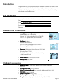
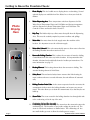
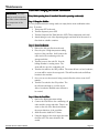
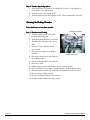
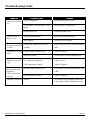
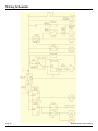
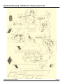
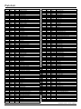
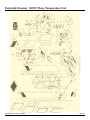
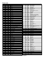
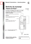
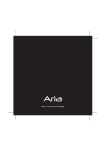
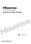
Fountain Classic
™
Installation and
Owner’s Manual
Page 16
4120 NW 44th St • Lincoln, NE 68524 USA
Tel: 402.467.9300␣ •␣ Toll Free in the USA: 800.875.5915 • Fax: 402.467.9393
www.purewaterinc.com
Page 2
Fountain Classic Owner’s Manual
Table of Contents
Important Safety Information ............................................................................................... 4
Introduction ........................................................................................................................................ 5
For the Record .................................................................................................................................. 5
Included With Your Distiller ................................................................................................... 5
Optional Accessories .................................................................................................................... 5
Getting to Know the Fountain Classic ............................................................................. 6
Installation ........................................................................................................................................... 8
Maintenance .................................................................................................................................... 11
Post Filter Changing and Steam Sterilization ............................................... 11
Cleaning the Boiling Chamber ................................................................................. 12
Troubleshooting Guide ............................................................................................................ 13
Wiring Schematic ........................................................................................................................ 14
Exploded Drawing 48998 ...................................................................................................... 15
Parts List 48998 ........................................................................................................................... 16
Exploded Drawing 48999 ...................................................................................................... 17
Parts List 48999 ........................................................................................................................... 18
Fountain Classic Owner’s Manual
Page 3
Important Safety Information
IMPORTANT: This
distiller is designed to be
used only with Pure
Water, Inc. accessories
and replacement components.
Page 4
•
If you are not sure that your electrical outlet is properly grounded or that the circuit
protection is correct, have it checked by a qualified electrician.
•
Operate indoors only.
•
The area must be well ventilated.
•
WARNING: Disconnect from the power source before assembling, adjusting or
servicing this appliance.
•
NEVER immerse the distiller in water or any other liquid.
•
NEVER operate the distiller with a damaged cord or allow the cord to become
exposed to hot surfaces.
•
DO NOT use an extension cord or any adapters.
•
DO NOT let children play with the distiller.
•
Wait at least 30 minutes after the distiller is off before draining or handling the
boiling chamber.
•
Do not run the dispenser water heater or water cooler when there is no water in the
storage tank.
•
The physiological effects of the operation of this distiller, beneficial or otherwise
have not been investigated by U.L.
•
The installation and use of this product must comply with all applicable state and
local laws and regulations.
•
If the unit was placed on its side for transport, be sure to allow the unit to stand
upright for at least four hours before plugging unit in.
•
Do not locate the unit in an area where the temperature falls below freezing.
Fountain Classic Owner’s Manual
Introduction
Congratulations on purchasing the finest water distillation system on the market. With
proper care and attention, the Fountain Classic will give many years of top performance
and high-quality drinking water. Please read this manual thoroughly before installing
and operating your Fountain Classic.
For the Record
The model and serial number are found on the back panel. You should record all the
necessary information below for future reference.
Date:
Model:
Fountain Classic
Serial Number:
Purchased from:
Telephone:
Included with Your Distiller
•
Incoming Water Hook-up. Includes:
Saddle tapping valve (Part # 9514)
15 feet of 1/4” food-grade tubing (Part # 9526-15R)
1/4”S x 1/4”T speedfit elbow (Part # 221-9006)
saddle
tapping valve
speedfit
elbow
1/4” tubing
•
Post Filter. Includes:
Post filter (Part # 9406A)
(2) 3/8”T x 3/8”S speedfit elbows (Part # 9614)
Silicone tubing (Part # 9541)
silicone
tubing
post filter
speedfit elbows
•
Power cord* (May not be included in some 240V units)
(US version Part # 7276)
*For 240V units, power cord must be at least 10 Amp
at 240V grounded cord
power cord
•
•
Owners Manual (Not shown) (Part # 6338)
Warranty Card (Not shown)
Optional Accessories
•
•
•
•
•
•
•
Fountain Classic Owner’s Manual
Distiller Day Timer
Timer. Allows you to limit the hours of water production.
(Part # 733)
Cup Dispenser, Metal
Metal. (Part # 110-9031)
Lumen™ Cleaner and Descaler for cleaning the boiling tank. ( Part # 6603)
5 oz. Cups
Cups. (Part # 110-9032)
Stainless steel polish
polish. (Part # 6606)
Post filter replacement cartridge
cartridge. (Part # 9406A)
Pump kit to attach the pump for icemaker hookup. (Part # 735)
Page 5
Getting to Know the Fountain Classic
Photo
Display
Here
1
1.
Photo Display
Display—This is a backlit area to display photos or advertising. Several
optional displays are available from Pure Water, Inc. or from your local distributor.
2.
Water Dispensing Area
Area—Three temperature units have dispensers for Hot
Water, Room Temperature Water, and Cold Water and the two temperature
unit has dispensers for Room Temperature Water and Cold Water. The
Controls for these are listed in items 14 and 15.
3.
Drip Tray
Tray—The hidden drip tray collects water that spills from the Dipsensing
Area. This must be routinely emptied to prevent overflows and spillage.
4.
Water Inlet
Inlet—Raw water from the local supply enters the machine at this
location. It is important to use the cold water supply.
5.
Water Inlet Solenoid
Solenoid—This valve automatically opens to allow water to flow into
the Boiling Chamber when the water level is low.
6.
Removable Boiling Chamber
Chamber—This is where the raw water is heated to boiling.
Contaminants from the water stay in this chamber. It is important that this
chamber is drained and periodically cleaned of residue per instructions. For
more information see page 11.
7.
Heating Element
Element—This heating element heats the raw water to boiling. The
standard heating element is 1400 Watts.
8.
Safety Reset
Reset—This mechanical safety feature ensures that if the heating element continues when not covered with water, the unit will turn off automatically.
9.
Boiling Chamber Drain Valve
Valve—As the steam evaporates from the raw water, the
contaminants in the water in the boiling chamber can become very concentrated. This valve allows you to drain the contaminants off, so that they do not
build up.
2
3
10. Steam Tube
Tube—The steam created in the boiling chamber rises through this tube
to the condensing coil at the top of the unit.
11. Condensing Coil and Fan Assembly
Assembly—The steam from the steam tube enters the
condensing coil. The fan turns on, and sends cooling air past the coil. The
steam is cooled and condenses to distilled water. The condensing coil has
two small volatile gas vents to allow the volatile gases to escape.
Page 6
Fountain Classic Owner’s Manual
12.
13.
14.
Post Filter
Filter—The carbon filter enhances the flavor of the distilled water
before it enters the storage tank.
11
Distilled Water Storage Tank
Tank—This tank holds distilled water for use
through any of the water spigots. This tank contains floats that turn the
distiller off when full, and turns the distiller back on when the tank is 1/3
empty.
12
Water Dispenser Section
Section—This section is composed of either two or three
main sections, depending on your unit:
a. The hot water tank holds up to 3/8 gallon, and quickly heats the water
for use at the hot water spigot. The hot water temperature is adjustable from 140˚F to 190˚F. (Three temperature unit only)
10
b. The cold water tank holds up to 3/4 gallon, and chills the water for use
at the cold water spigot. The cold temperature is adjustable from 40˚F
to 50˚F.
c. The reservoir holds up to 9.25 gallons for use at the room temperature
water spigot. The water is at room temperature.
13
14
15.
Dispenser Hot Water Switch*
Switch*—This switch allows the dispenser to heat the
water for the hot water spigot.
Important: This switch must be in the OFF position until the storage tank
is filled the first time.
*Three temperature unit only
15
16. Main Electrical Control Box
Box—This electrical
Fan
box has all of the controls for the unit.
Distiller Power Switch
Switch—Controls the power for
the distillation unit.
Cooler Power Switch
Switch—Controls the power to
the cooler and hot tank.
Light Power Switch
Switch—Turns the lighted display
Circuit Breaker Plug Adapter
panel on the front of the unit on.
Fan Power Switch
Switch—This switch is used to either
Steam Sterilize (when the switch is off), or distill (when the switch is on).
Steam Sterilizing instructions are found on page 10.
Circuit Breaker
Breaker—This breaker provides electrical circuit protection for the
unit.
Plug Adapter
Adapter—This plug provides power for the entire unit through the
power cord.
Distiller Cooler
Power Power Light
17.
4
5
16
6
8
9
7
17
Emergency Overflow Float
Float—Turns the unit off automatically if water fills the bottom pan.
Fountain Classic Owner’s Manual
Page 7
Installation
CAUTION:
CAUTION:
NOTE
NOTE::
NOTE
NOTE::
NOTE
NOTE::
DO NOT use a hot water line for the raw water supply.
DO NOT turn the saddle tapping valve handle before or during installation. Be sure the piercing lance does not protrude beyond the rubber
gasket. Failure to do this may result in damage to the piercing needle.
The use of softened water for the raw water supply is recommended to
minimize scale buildup in the boiling tank and drain valve.
The Fountain Classic comes standard with a saddle-tapping valve. In
some areas a saddle-tapping valve may not be permitted. In such instances, contact your authorized Pure Water Distributor for other water
line connection options.
Do not plug the unit into the power source until instructed to do so.
The installation of the Fountain Classic is very simple. The steps are as follows:
1. Position the unit in a well ventilated area.
2. Connect the unit to the water supply so that it can operate automatically.
3. Plug the unit into an appropriate power plug.
4. Start the machine.
5. Install the Photo Display
6. Steam Sterilize the machine.
7. Start Distillation.
8. Rinse the Post Filter.
9. Turn the dispensing unit on.
Step 1 Positioning the unit:
The unit should be positioned on a level floor that has an appropriate electrical plug
and water supply available. If the ground is not completely level, the leveling feet on the
bottom of the unit can be used to adjust the machine.
Note: The Fountain
Classic must be positioned on a level surface.
Allow at least 2” of
clearance behind unit for
proper air circulation.
Page 8
Step 2 Connecting the water supply:
This unit comes complete with a saddle-tapping valve to connect the distiller water inlet
directly to an existing waterline.
Connecting the Saddle Tapping Valve:
1. Turn the raw water supply off.
2. Install the saddle tapping valve on the COLD
water copper tubing so the outlet is in a convenient direction. See figure.
3. Tighten screws evenly. Brackets should be
parallel. Tighten firmly. Do not over tighten.
4. Connect tubing to the saddle tapping valve
Saddle Tapping Valve
outlet.
5. Plug the other end of the 1/4” tubing into the Raw Water Inlet on the back of the
Fountain Classic.
Fountain Classic Owner’s Manual
6. Turn the saddle tapping valve handle clockwise until you feel it is firmly seated.
Note: You have now pierced the copper tube and the valve is closed.
7. Turn the handle counterclockwise to open the valve. Turn the household water
supply ON and check all connections for leaks.
8. Open the saddle tapping valve completely. Check the line for leaks. Tighten where
required.
Step 3 Plug the unit into an appropriate power plug:
Locate the power cord in the parts kit bag. Make sure that
the electrical outlet rating exceeds the requirements for this
unit (15 Amp dedicated circuit). Install the female end of
the power cord into the adapter on the main electrical
control box. Plug the unit into the wall outlet.
Distiller Power
Cooler Power
Light
Fan
Step 4 Start the Machine:
Before starting the machine the switches should be in the
following positions:
Distiller Power:
Fan Switch:
Light Switch:
Cooler Power:
Dispenser Hot Water Switch*:
OFF
OFF
OFF
OFF
OFF
Circuit Breaker
Plug Adapter
*Three temperature unit only
Now the distiller power can be turned on. The unit will
energize. The boiling tank will automatically begin to fill with
water and start to heat up.
Never turn the dispenser hot water switch on
WARNING:
without water in the hot tank. (Three temperature unit only)
Step 5 Installing the Photo Display:
The cooler transparency will be packed separately and
require installation.
To install the color transparency:
1. Remove the screws in the top panel of the unit. Remove the top panel.
2. Slide the plastic transparency cover up and out of the unit.
3. Place the 2 bulbs into their sockets. Turn into place.
4. Place transparency behind the transparency cover and lower into place.
5. Replace the top panel and screw into place.
Now you can turn the light switch ON.
Fountain Classic Owner’s Manual
Page 9
Step 6 Steam Sterilization of the Machine:
Use the high temperature tubing, included in the parts
kit in place of the post filter. It will connect the outlet
end of the condensing coil to the storage tank inlet.
This tube must be used because the post filter cannot
withstand the temperature of the steam. Now the
boiling chamber is creating steam. The steam will rise
up to the condensing coil. Normally the fan would
cool the steam and it would change back to water
form. The fan switch is turned off, so there is no way for the steam to cool and condense. Steam will be sent to the storage tank. This will heat the tank and kill any
bacteria in the machine. Once you can see that steam is being created, allow the unit
to steam for 25 minutes. (Total time spent is approximately 1 hour.)
Step 7 Distillation:
After the unit has adequately steam sterilized,
turn the Fan switch to the ON position. The fan
will start and begin to cool the steam. After a
few minutes, distilled water will be created.
Step 8 Rinse the Post Filter:
Remove the high temperature tubing used for
Steam Sterilization. Connect the Post Filter to
the condensing coil outlet and the storage tank
inlet. There is an arrow on the side of the filter
that indicates the proper direction of the post
filter. Allow the unit to distill for 5-6 hours.
Using the spigots in the front, empty the water
from the unit. This water should be discarded.
(Three temperature unit owners: be sure to
draw water from the hot water spigot so
any air in the lines or tank is released.)
Step 9 Turn the dispensing unit on:
Allow the distiller to operate for an additional 5-6 hours. Several gallons of water will
be in the storage tank. It is now safe to turn the Cooler Power switch to ON, and the
Dispenser Hot Water Switch to ON. (Three temperature unit only.)
Page 10
Fountain Classic Owner’s Manual
Maintenance
Post Filter Changing and Steam Sterilization
IMPORTANT: This tube
must be used, because the
post filter cannot withstand
the temperature of the
steam.
Every 2000 operating hours (3 months if the unit is operating continuouly):
Step 1 Empty the Distiller:
It is very important that the storage tanks are empty before steam sterilization takes
place. To do this:
1. Turn power OFF to the unit.
2. Turn the dispenser power OFF.
3. Turn the Dispenser Hot Tank Switch to OFF. (Three temperature unit only.)
4. Attach tubing to each of the dispensing spigots and drain all of the water to a
floor drain or suitable container.
Step 2 Steam Sterilization:
1. Remove the old post filter from the unit.
2. Place the piece of high temperature tubing
in place of the post filter. It will connect the
outlet end of the condensing coil to the
storage tank inlet.
3. Turn the power to the unit ON. Now the
boiling chamber is creating steam. The
steam will rise up to the condensing coil.
4. Turn the fan switch to the OFF position. The steam will not cool and condense,
so steam will be sent to the storage tank. This will heat the tank and kill any
bacteria in the machine.
5. Once you can see that steam is being created, allow the unit to steam for 25
minutes.
6. Turn the Fan switch to the ON position. The
fan will start and begin to cool the steam.
After a few minutes distilled water will start to
be created.
Step 3 Rinse the Post Filter:
1. Remove the high temperature tubing.
2. Connect the Post Filter to the condensing coil
outlet and the storage tank inlet. There is an
arrow on the side of the filter that indicates
the proper direction of the post filter.
3. Allow the unit to distill for 5-6 hours.
4. Using the spigots in the front, empty the water
from the unit. This water should be discarded.
Fountain Classic Owner’s Manual
Page 11
Step 4 Turn the dispensing unit on:
1. Allow the distiller to operate for an additional 5-6 hours. Several gallons of
water will be in the storage tank.
2. Turn the Cooler Power switch to ON.
3. Turn the Dispenser Hot Water Switch to ON. (Three temperature unit only.)
Cleaning the Boiling Chamber
Every 2000 hours or every three months:
Electrical Connection
Step 1 Shutdown and Cooling:
1. Turn the distiller switch to the OFF
position and unplug unit.
2. Allow the boiling chamber to cool down.
3. Turn the unit so that the rear is accessible.
4. Remove 4 screws and take off rear
access panel.
5. Disconnect the tubing to the boiling
chamber.
Tubing Connections
6. Disconnect the electrical connections to
the boiling chamber.
7. Pull the boiling chamber out of the unit.
8. Drain into a sink.
9. Fill the boiling chamber with water to the top of the scale line.
10. Add 4-6 tablespoons of Lumen™ descaling powder to the boiling chamber.
11. Allow the lumen to soften any scale (allow 12-24 hours for scale to soften).
12. Drain and rinse boiling chamber.
13. Reconnect tubing and electrical connections.
14. Turn the distiller switch to the ON position.
Page 12
Fountain Classic Owner’s Manual
Troubleshooting Guide
Symptom
Unit does not operate.
Unit runs, but exhaust is cool.
Water has bad smell
or taste.
Probable Cause
Solution
Unit not plugged in.
Plug unit into power source.
Power failure, circuit breaker or fuse
blown.
Reset breaker or replace fuse.
Power switch OFF.
Turn power switch ON.
Heating element failure.
Replace the heating element.
Reset tripped.
Push in the reset button.
Post filter is depleted or carry-over
problem.
Replace the post filter. Drain the boiling
tank.
Unit makes a hissing Faulty heating element or fan.
noise.
Improper air flow.
Adjust or Replace.
Position unit in a well ventilated area.
No coolant in compressor.
Call for service.
Cold temperature control.
Adjust or Replace.
Hot water switch turned OFF.
Turn switch ON when distilled water tank
is full.
(Three temperature
unit only.
Hot temperature control.
Adjust or Replace.
Leaking of any kind.
Various.
Disconnect power and shut off the feed
water supply. Call for immediate service.
Dispenser not cooling.
No hot water from
dispenser.
Fountain Classic Owner’s Manual
Page 13
Wiring Schematic
Page 14
Fountain Classic Owner’s Manual
Exploded Drawing: 48998 Two Temperature Unit
Fountain Classic Owner’s Manual
Page 15
Parts List
Key #
1
2
3
4
5
6
7
8
*
9
10
11
12
13
14
15
16
17
18
*
19
20
21
22
*
23
24
25
*
26
27
28
*
29
30
31
32
33
34
35
36
37
38
39
40
41
42
43
44
45
46
47
48
49
50
51
52
53
54
55
56
57
58
59
60
61
63
64
65
66
67
68
69
70
71
72
73
74
Key #
Page 16
120V P/N
8009
6022
519
69
533
9085
402B
224-0003
406
9045
48003
9220
7230
7127
9041
7200
516
9030
8070
662
9082
9024
9080
6021
604
513
9018
9519
644
6005
9303
400A-02
727
9302
48018
7069
9079
9108
48502-02
9043
9314
9095
9316
7206
9018
9110
9023
9059
7228
7232
219-0227
7275
9315
7129
7133
7136
7148
7139
9046
9061
48503-01
48032
9009
9310
9301
9311
9541
8014
48019
223-0002
110-9057
48506-02
9323
9321
7138
9322
9001
9406
120V P/N
240V P/N
8009
6022
519
69
533
9085
402B
224-0003
406
9045
48003
9220
7230
7127
9041
7200
516
9030
8070
662
9082
9024
9080
6021
604
513
9018
9519
644
6005
9303V
400A-02
727V
9302
48018
7069
9079
9108
48502-02
9043
9314V
9095
9316
7206V
9018
9110
9023
9059
7228
7232
219-0227
7275
9412
7129
7133
7136
7148
7139
9046
9061
48503-01
48032
9009
9310
9301
9311
9541
8014
48019
223-0002
110-9057
48506-02
9323V
9321V
7138
9322
9001
9406
240V P/N
Description
Lid Knob with Stud
Lid O-Ring
Lid Disc
Lid Gasket
Gasket Retainer
Lid Spring
Lid Crossbar with Nut
Locknut, 1/4-20
Lid Assy (Includes #1-8)
Nut, 1/4-20
Switch Cover
Bushing, 1” Plastic
Wire Holder
Tab, Adapt.
Hex Nut, 4-40
Microswitch
Switch Plate
Screw, 4-40 x 1-1/8”
Nylon Spacer
Microswitch Kit (Includes #14-#18)
Actuating Arm
Set Screw
Float Bushing, Teflon
Float O-ring
O-Ring and Bushing Kit (Includes #21 and #22)
Float Rod
#6 Hex Nut
Float Ball
Float Kit (Includes #19-#25)
Heating Element Gasket
Heating Element (1400W)
Clamp. Studded, Heating Element Kit #601
Heating Element Kit (Includes #26-#28, 54, 58)
Drain Valve
Drain Tube
Reset, Heating Element Kit #601
Nut, Acorn
Handle, Polymide
Boiling Tank, Welded
Hex Nut, #8
Transformer
Screw, #8
Relay, 24V, DPST
Relay, SPDT
Hex Nut, #6
Buss Connector, 8 x 8
Screw, #6
Screw, #10
Switch, On/Off *Kit #642
Switch, Lighted *Kit #648
Hour Meter
Connector IEC
Circuit Breaker, Resetable
Conn, 5 Pin Female
Conn, 3 Pin Female
Conn, 2 Pin Female
Conn, 4 Pin Female
Conn, 6 Pin Female
Washer, Lock #10
Hex Nut, #10
Welded Elec. Box
Elec. Box Lid
Washer, Flat, 1/4”
6” O-ring
Coupler, Plastic
5” O-Ring
Silicone Tubing
Air Filter
Bracket, S/T
Screw, 1/4-20
Storage Tank Float Kit # 677
Storage Tank, Studded
Light Ballast *Kit # 731 & #731V
Starter *Kit #732 & #732V
Conn, 6 Pin Male
Starter Base
Screw, #4
Filter, Carbon *Kit #9406A
Description
75
9614
76
48507
77
48508
78
48509
79
7246
80
9324
81
48040
82
9320
83
402C-01
84
548
*
410A
85
9003
86
541
87
7092
88
7010
89
9092
*
639
*
653
90
9304
91
9029
92
7026
93
48028
94
48029
95
48517A
96
48044
97
45518
101
9317
102
7147
103
9111
104
48041
105
9526
106
7219
107
9638
108
7134
109
48039
110
48501
111
48030
112
221-9000
113
48504
114
6049
115
9592
116
6103
117
7132
118
9048
119
32029
120
213-0037
121
48521A
122
9319
124
9306
125
9305
126
9325
127
48513
128
48024C
129
48024B
130
48025
131
7276
132
7128
133
48505
134
9408
135
6070
136
9328
137
48027
138
48512
139
9047
140
510
141
424A
142
9032
143
9332
148
48036
149
9326
150
9605
151
9621
152
221-0056
***
48525
* Parts Kit
** Sold Separately
*** Not Shown
9614
48507
48508
48509
7246
9324
48040
9320
402C-01
548
410A
9003
541
70103A
7010
9092
639
653V
9304
9029
7026
48028
48029
48517AV
48044
45518
9317
7147
9111
48041
9526
7219V
9638
7134
48039
48501
48030
221-9000
48504
6049
9592
6103
7132
9048
32029
213-0037
48521A
9319
9306
9305
9325
48513
48024C
48024B
48025
**
7128
48505
9408
6070
9328
48027
48512
9047
510
424A
9032
9332
48036
9326
9605
9621
221-0056
48525
Elbow, 3/8”
Short Coil Bracket
Med. Coil Bracket
Tall Coil Bracket
Cable Tie, Black
Lamp Holder
Light Housing
Light Bulb *Kit #730
Crossbar, S/T
Lid, Storage Tank
Lid, S/T (Includes #1,2,8,58,83,84)
Nut, #8 Nylock
Fan Bracket
Fan Motor
Fan Blade
Push Nut
Fan Blade Kit (Includes #88 & #89)
Fan and Motor Kit (Includes #87-#89)
Condensing Coil *Kit #729
Sheetmetal Screw, #10
Connector, Gray, 3/8”
Top Back Panel
Bottom Back Panel
Compressor Assy. Room & Cold
Cooler Bracket
Cooler Baffle
T-Bar Clamp, 6”
Conn. 4 Pin Male
Buss Connector, 2x3x4
Ballast Plate
Tubing, 1/4” OD
Inlet Solenoid Valve *Kit #728 & #728V
Elbow, Speedfit, 3/8” x 1/4”
Conn. 3 Pin Male
Valve Bracket
Welded Steam Tube
Insulation, Set, B/T and Pipe
Speedfit, Bulkhead
Welded Frame
Rubber Washer
Adjustable Leg
Hose Clamp, Plastic
Conn. 2 Pin Male
Nut, 1/8” MPT
Bracket, Float
Safety Float
Welded Faucet Bracket, 2 Hole
Rubber Washer
White Faucet
Blue Faucet
Graphic
Front Cladding
Left Cladding
Right Cladding
Top Cladding
Power Cord
Conn. 5 Pin Male
Welded Frame
Nylon Spacer
Wire Trim
Wire Clip
Drip Pan Cover
Drip Pan
Clip, J Type
Reset Plate, Insulated
Reset Plate, SS
Lock Washer, 1/4”
Compressor Thermostat
Electrical Box Support
Plastic Graphic Cover
Elbow, Speedfit, 3/8” x 1/4”
Connector, Speedfit, 3/8”X1/4”
Plug, 3/8”, Speedfit
Wire Kit
Fountain Classic Owner’s Manual
Exploded Drawing: 48999 Three Temperature Unit
Fountain Classic Owner’s Manual
Page 17
Parts List
Key #
1
2
3
4
5
6
7
8
*
9
10
11
12
13
14
15
16
17
18
*
19
20
21
22
*
23
24
25
*
26
27
28
*
29
30
31
32
33
34
35
36
37
38
39
40
41
42
43
44
45
46
47
48
49
50
51
52
53
54
55
56
57
58
59
60
61
62
63
64
65
66
67
68
69
70
71
72
73
74
75
120V P/N
8009
6022
519
69
533
9085
402B
224-0003
406
9045
48003
9220
7230
7127
9041
7200
516
9030
8070
662
9082
9024
9080
6021
604
513
9018
9519
644
6005
9303
400A-02
727
9302
48018
7069
9079
9108
48502-02
9043
9314
9095
9316
7206
9018
9110
9023
9059
7228
7232
219-0227
7275
9315
7129
7133
7136
7148
7139
9046
9061
48503-01
48032
9009
9310
9301
9311
9922
9541
8014
48019
223-0003
110-9057
48506-02
9323
9321
7138
9322
9001
9406
9614
240V P/N
8009
6022
519
69
533
9085
402B
224-0003
406
9045
48003
9220
7230
7127
9041
7200
516
9030
8070
662
9082
9024
9080
6021
604
513
9018
9519
644
6005
9303V
400A-02
727V
9302
48018
7069
9079
9108
48502-02
9043
9314V
9095
9316
7206V
9018
9110
9023
9059
7228
7232
219-0227
7275
9412
7129
7133
7136
7148
7139
9046
9061
48503-01
48032
9009
9310
9301
9311
9922
9541
8014
48019
223-0002
110-9057
48506-02
9323V
9321V
7138
9322
9001
9406
9614
Description
Lid Knob with Stud
Lid O-Ring
Lid Disc
Lid Gasket
Gasket Retainer
Lid Spring
Lid Crossbar with Nut
Locknut, 1/4-20
Lid Assy (Includes #1-8)
Nut, 1/4-20
Switch Cover
Bushing, 1” Plastic
Wire Holder
Tab, Adapt.
Hex Nut, 4-40
Microswitch
Switch Plate
Screw, 4-40 x 1-1/8”
Nylon Spacer
Microswitch Kit (Includes #14-#18)
Actuating Arm
Set Screw
Float Bushing, Teflon
Float O-ring
O-Ring and Bushing Kit (Includes #21 and #22)
Float Rod
#6 Hex Nut
Float Ball
Float Kit (Includes #19-#25)
Heating Element Gasket
Heating Element (1400W)
Clamp. Studded, Heating Element Kit #601
Heating Element Kit (Includes #26-#28, 54, 58)
Drain Valve
Drain Tube
Reset, Heating Element Kit #601
Nut, Acorn
Handle, Polymide
Boiling Tank, Welded
Hex Nut, #8
Transformer
Screw, #8
Relay, 24V, DPST
Relay, SPDT
Hex Nut, #6
Buss Connector, 8 x 8
Screw, #6
Screw, #10
Switch, On/Off *Kit #642
Switch, Lighted *Kit #648
Hour Meter
Connector IEC
Circuit Breaker, Resetable
Conn, 5 Pin Female
Conn, 3 Pin Female
Conn, 2 Pin Female
Conn, 4 Pin Female
Conn, 6 Pin Female
Washer, Lock #10
Hex Nut, #10
Welded Elec. Box
Elec. Box Lid
Washer, Flat, 1/4”
6” O-ring
Coupler, Plastic
5” O-Ring
Hose Clamp
Silicone Tubing
Air Filter
Bracket, S/T
Screw, 1/4”-20
Storage Tank Float Kit # 677
Storage Tank, Studded
Light Ballast *Kit # 731 & #731V
Starter *Kit #732 & #732V
Conn, 6 Pin Male
Starter Base
Screw, #4
Filter, Carbon *Kit #9406A
Elbow, 3/8”
Key #
120V P/N
76
48507
77
48508
78
48509
79
7246
80
9324
81
48040
82
9320
83
402C-01
84
548
*
410A
85
9003
86
541
87
7092
88
7010
89
9092
*
639
*
653
90
9304
91
9029
92
7026
93
48028
94
48029
95
48517
96
48044
97
45518
98
48007
99
9318
100
9033
101
9317
102
7147
103
9111
104
48041
105
9526
106
7219
107
9638
108
7134
109
48039
110
48501
111
48030
112
221-9000
113
48504
114
6049
115
9592
116
6103
117
7132
118
9048
119
32029
120
213-0037
121
48521
122
9319
123
9307
124
9306
125
9305
126
9325
127
48513
128
48024C
129
48024B
130
48025
131
7276
132
7128
133
48505
134
9408
135
6070
136
9328
137
48027
138
48512
139
9047
140
510
141
424A
142
9032
143
9332
144
9331
145
9334
146
9330
147
9333
148
48036
149
9326
150
9605
***
48525
* Parts Kit
** Sold Separately
*** Not Shown
240V P/N
48507
48508
48509
7246
9324
48040
9320
402C-01
548
410A
9003
541
70103A
7010
9092
639
653V
9304
9029
7026
48028
48029
48517V
48044
45518
48007
9318
9033
9317
7147
9111
48041
9526
7219V
9638
7134
48039
48501
48030
221-9000
48504
6049
9592
6103
7132
9048
32029
213-0037
48521
9319
9307
9306
9305
9325
48513
48024C
48024B
48025
**
7128
48505
9408
6070
9328
48027
48512
9047
510
424A
9032
9332
9331
9334
9330
9333V
48036
9326
9605
48525
Description
Short Coil Bracket
Med. Coil Bracket
Tall Coil Bracket
Cable Tie, Black
Lamp Holder
Light Housing
Light Bulb *Kit #730
Crossbar, S/T
Lid, Storage Tank
Lid, S/T (Includes #1,2,8,58,83,84)
Nut, #8 Nylock
Fan Bracket
Fan Motor
Fan Blade
Push Nut
Fan Blade Kit (Includes #88 & #89)
Fan and Motor Kit (Includes #87-#89)
Condensing Coil *Kit #729
Sheetmetal Screw, #10
Connector, Gray, 3/8”
Top Back Panel
Bottom Back Panel
Compressor Assy.
Cooler Bracket
Cooler Baffle
Elbow, 3/8”
Plastic Connector
Screw, #6
T-Bar Clamp, 6”
Conn. 4 Pin Male
Buss Connector, 2 x 3 x 4
Ballast Plate
Tubing, 1/4” OD
Inlet Solenoid Valve *Kit #728 & #728V
Elbow, Speedfit, 3/8” x 1/4”
Conn. 3 Pin Male
Valve Bracket
Welded Steam Tube
Insulation, Set, B/T and Pipe
Speedfit, Bulkhead
Welded Frame
Rubber Washer
Adjustable Leg
Hose Clamp, Plastic
Conn. 2 Pin Male
Nut, 1/8” MPT
Bracket, Float
Safety Float
Welded Faucet Bracket
Rubber Washer
Red Faucet
White Faucet
Blue Faucet
Graphic
Front Cladding
Left Cladding
Right Cladding
Top Cladding
Power Cord
Conn. 5 Pin Male
Welded Frame
Nylon Spacer
Wire Trim
Wire Clip
Drip Pan Cover
Drip Pan
Clip, J Type
Reset Plate, Insulated
Reset Plate, SS
Lock Washer, 1/4”
Compressor Thermostat
Switch, Hot Tank
Limiter, Hot Tank
Hot Tank Thermostat
Hot Tank Heater
Electrical Box Support
Plastic Graphic Cover
Elbow, Speedfit, 3/8” x 1/4”
Wire Kit
Form #6338, ©2000, Pure Water, Inc.
U.S. and Foreign Patents Pending