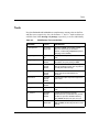
1
PCN Process User Guide
Part No. 301945-A
May 15, 1998
4401 Great America Parkway
Santa Clara, CA 95054
8 Federal Street
Billerica, MA 01821
Copyright © 1998 Bay Networks, Inc.
All rights reserved. This is an unpublished document meant for internal use only.
The information in this document is proprietary to Bay Networks, Inc., and subject to change without notice.
The software described in this document is, unless otherwise trademarked in the text, the property of Bay Networks
and may only be used as such.
Any program and information contained herein may contain additional restrictions on use and disclosure.
Trademarks
ACE, AFN, AN, BCN, BLN, BN, BNX, CN, FN, FRE, GAME, LN, Optivity, PPX, Quick2Config, and Bay Networks
are registered trademarks and Advanced Remote Node, ANH, ARN, ASN, Bay•SIS, BayStack, BayStream, BCC,
BCNX, BLNX, EZ Install, EZ Internetwork, EZ LAN, IP AutoLearn, PathMan, RouterMan, SN, SPEX, Switch
Node, System 5000, Bay Networks Press, and the Bay Networks logo are trademarks of Bay Networks, Inc.
Microsoft, MS, MS-DOS, Win32, Windows, and Windows NT are registered trademarks of Microsoft Corporation.
All other trademarks and registered trademarks are the property of their respective owners.
Quick Reference
Frequently used directories:
~/your_project or /xxx/project—Your working directory with project- and BOM-related files
/hw/tools—BNE UNIX mount point for tools and scripts
/swi/tools—BNW mount point for tools and scripts
/hw/tools/scripts—Engineering- and BNE-oriented BOM and PCN-related scripts
/swi/tools/scripts—Engineering- and BNW-oriented BOM and PCN-related scripts
/baydir—/bayeast and /baywest prefix PCN tool and data directories depending on East or West Coast locations
/baydir/dra/common—Commonly-available area for 20-day file storage for mechbom
/baydir/dra/utils—EDA-oriented BOM and PCN-related scripts
/baydir/dra/2brel/mech, docs, programs—Temporary location for files to be “released” to EDA (not ECO) control
/baydir/dra/rel, pcn_data—Permanent location for files and PCNs that have been “released”
And HTML pages:
http://bayweb.baynetworks.com/engserv—EDA home page
http://bayweb.baynetworks.com/engserv/tools.html—EDA’s BOM tools
http://bayweb.baynetworks.com/engserv/pdf/mainpdf.html—EDA print room
http://hwtools—Hardware Engineering tools and procedures
See Appendix A for more information on the system and directory infrastructure.
ii
301945-A
Contents
About This Guide
Before You Begin Reading ...............................................................................................xiii
Conventions .....................................................................................................................xiv
Acronyms .........................................................................................................................xiv
Reading This Guide with Adobe Acrobat ......................................................................... xv
Internal Support ...............................................................................................................xvi
Information Systems Central .....................................................................................xvi
Getting Help for BOM and SAP Processing .............................................................xvii
Chapter 1
Getting Started (An Overview)
Executive Overview ........................................................................................................1-2
Starting Work on a Project ..............................................................................................1-3
Using Recognized Parts .................................................................................................1-4
Getting New Parts ..........................................................................................................1-5
Using EDA Data Servers ................................................................................................1-6
Creating and Updating BOMs .........................................................................................1-7
Creating an Initial BOM ............................................................................................1-7
Updating a BOM .......................................................................................................1-8
Uploading a BOM ...........................................................................................................1-9
Reading PCNs ..............................................................................................................1-10
Understanding the PCN/BOM Process ........................................................................1-11
Finding BOMs on the Web ............................................................................................1-12
Chapter 2
Starting a Project
Obtaining Appropriate Accounts .....................................................................................2-1
Setting up Your Environment ..........................................................................................2-2
Creating a New Project ...................................................................................................2-3
PCN Process User Guide (301945-A)
iii
Managing a Project’s Majordomo Email List ...................................................................2-4
Setting up the Initial Email List .................................................................................2-4
Using Majordomo Commands ..................................................................................2-4
Chapter 3
Using and Getting Part Numbers
Finding Parts ..................................................................................................................3-1
In ViewLogic .............................................................................................................3-1
In UNIX Directories ..................................................................................................3-2
Using Part Manager to Find Part Numbers .......................................................3-2
Using UNIX Script Commands to Find Part Numbers .......................................3-2
On the Web ..............................................................................................................3-3
Using partmgr to Update or Get a New Part Number .....................................................3-4
Getting New Part Numbers ......................................................................................3-4
Generating Part Numbers for an Initial BOM .....................................................3-6
Updating Part Numbers ............................................................................................3-8
Canceling Parts ........................................................................................................3-9
Printing Part Requests ...........................................................................................3-10
Part Number Availability ...............................................................................................3-10
SAP and Timing Issues ..........................................................................................3-10
Viewlogic Library and Timing Issues ......................................................................3-10
Chapter 4
Putting Data on EDA Servers
Introduction .....................................................................................................................4-1
The “To-Be-Released” Area .....................................................................................4-1
The PCN “Release” Area .........................................................................................4-2
Data Storage for Programmed Parts ..............................................................................4-3
Providing Device Files for PALs ................................................................................4-4
Providing Device Files for EPROM and Flash PROM Devices ................................4-5
Mechanical Data .............................................................................................................4-6
Using Pro/E for Mechanical Revisions .....................................................................4-6
Using non-Pro/E Files ..............................................................................................4-7
Sending Layout Files ................................................................................................4-7
Putting Schematics in the /2brel/mech Directory .....................................................4-8
Doc Data .......................................................................................................................4-10
iv
Chapter 5
Creating and Updating BOMs
Overview .........................................................................................................................5-2
BOM Generating Programs ......................................................................................5-2
Configuration Files ...................................................................................................5-2
Input and Output directories .....................................................................................5-2
Creating BOMs ...............................................................................................................5-4
Structuring a BOM ...................................................................................................5-4
Example .............................................................................................................5-5
Creating a BOM with bn_bomprocess .....................................................................5-6
Using mechbom to Create or Update a BOM ..........................................................5-7
Creating an Initial Mechanical BOM ..................................................................5-8
Downloading a .saplis File from SAP .................................................................5-8
Updating a Mechanical BOM .............................................................................5-9
Using xcelbom to Create an Initial BOM ................................................................5-10
The Input Files ..............................................................................................................5-12
BOM Files ..............................................................................................................5-12
bn_bomprocess.ini ...........................................................................................5-12
part.saplis—The Previous BOM ......................................................................5-12
Include, Change, and Depop Files .........................................................................5-12
Include Files ....................................................................................................5-13
Depop Files .....................................................................................................5-14
Change Files ...................................................................................................5-14
The SAP List File ...................................................................................................5-15
The Configuration File ..................................................................................................5-16
Creating and Specifying a Configuration File .........................................................5-16
Using Configuration Files for Different Purposes ...................................................5-16
Specifying Configuration File Parameters ..............................................................5-17
The Output Files ...........................................................................................................5-20
Added Parts File .....................................................................................................5-20
AVL Update File .....................................................................................................5-21
Changes File ..........................................................................................................5-22
Lead Time File .......................................................................................................5-24
Log File ..................................................................................................................5-24
New BOM File ........................................................................................................5-26
PCN Process User Guide (301945-A)
v
Part List ..................................................................................................................5-26
Part and Assembly Cost File ..................................................................................5-27
Part Cost File .........................................................................................................5-27
Profile File ..............................................................................................................5-28
The Prototype Differences File ...............................................................................5-28
New SAP Upload File .............................................................................................5-30
Schematic Output ...................................................................................................5-31
Summary Overview of BOM Files ................................................................................5-32
Chapter 6
Generating PCNs and Uploading BOMs
Understanding What a PCN Is .......................................................................................6-1
Design Purpose of PCNs .........................................................................................6-2
How PCNs Affect Other Groups ...............................................................................6-2
Commodity Supplier Management and PPM ....................................................6-2
Component Engineering ....................................................................................6-3
Frequency of PCNs ..................................................................................................6-3
Pre-Upload Checklist ...............................................................................................6-3
Running bom_upload .....................................................................................................6-6
Getting the PCN Number .........................................................................................6-7
Confirming that the BOM Is Uploaded into SAP ......................................................6-8
Appendix A
Computer Infrastructure and Tools
Computer Infrastructure ................................................................................................. A-1
Tools .............................................................................................................................. A-3
Appendix B
Behind the Scenes
Beginning a New Project ............................................................................................... B-1
Processing of the Programmable Parts Directory ......................................................... B-2
Timing and cron Scripts ................................................................................................. B-3
cron Scripts ............................................................................................................. B-3
Scripts Run Manually .............................................................................................. B-3
Scheduled Processes ............................................................................................. B-4
....................................................................................................................................... B-4
vi
Appendix C
FAQ
Appendix D
Error Messages
partmgr Error Messages ................................................................................................ D-1
bn_bomprocess Messages ............................................................................................ D-2
Errors ...................................................................................................................... D-2
Warnings ................................................................................................................. D-4
bom_upload Error Messages ........................................................................................ D-5
Appendix E
Parts and Part Numbers
Part Numbers ................................................................................................................ E-1
Common Part Number Format ................................................................................ E-1
Legacy Part Numbers ............................................................................................. E-2
Wellfleet ............................................................................................................ E-2
SynOptics ......................................................................................................... E-2
Searching for and Revving Legacy Part Numbers ............................................ E-4
Tabbed Part Numbers ............................................................................................. E-4
When to Change Part Numbers .................................................................................... E-5
When to Pull a New Number ................................................................................... E-6
When to Change the Embedded Rev for a Part Number ........................................ E-6
Programmed Parts ............................................................................................ E-6
PCB Assemblies ............................................................................................... E-7
Custom Parts (Cables, Sheet Metal, Fabs, Labels, Bezels, etc.) ..................... E-7
Custom Parts (Manuals and Software) ............................................................. E-7
Purchased Components (ICs, Connectors, Resistors, Caps, etc.) ................... E-7
When to Update the Minor Rev of a Part Number ......................................................... E-7
Programmed Parts .................................................................................................. E-8
PCB Assemblies ..................................................................................................... E-8
Custom Parts (Cables, Sheet Metal, Fabs, Labels, etc.) ......................................... E-9
Custom Parts (Manuals and Software) ................................................................... E-9
Purchased Components (ICs, Resistors, Caps, etc.) .............................................. E-9
BOM Structures ............................................................................................................. E-9
Class Codes (Material Groups) ................................................................................... E-12
PCN Process User Guide (301945-A)
vii
Appendix F
References
Glossary
Index
viii
Figures
Figure 1-1.
Figure 5-1.
SAP, BOM, PCN Process Overview .......................................................1-11
Excel Spreadsheet Template for xcelbom .............................................5-10
PCN Process User Guide (301945-A)
ix
x
Tables
•
EDA East Engineering Support ...............................................................xvii
•
EDA West Engineering Support ...............................................................xvii
Table 2-1.
Commonly Used Majordomo Commands ................................................2-5
Table 3-1.
Summary of Initial Parts to Take Out for a New Project ...........................3-7
Table 4-1.
Object Types for Programmable Parts .....................................................4-3
Table 5-1.
Input directories for Creating a BOM .......................................................5-3
Table 5-2.
Initial Parts for a Project ...........................................................................5-5
Table 5-3.
Config File Parameters ..........................................................................5-18
Table 5-4.
Table of BOM Processing Files ..............................................................5-32
Table 6-1.
Engineering Output Directories after BOM Uploads ................................6-6
Table A-1.
EDA Servers ........................................................................................... A-1
Table A-2.
EDA Directories and Links ...................................................................... A-2
Table A-3.
BOM-Related Tools and Utilities ............................................................. A-3
Table E-1.
Synoptics Document Codes .................................................................... E-3
Table E-2.
Other Numbering Formats ...................................................................... E-4
Table E-3.
Tabbed Part Numbers ............................................................................. E-5
Table E-4.
Reporting Relationships for BOMs ....................................................... E-10
Table E-5.
Build-to-Stock BOM Structuring ............................................................ E-11
Table E-6.
Build-to-Order BOM Structure .............................................................. E-12
Table E-7.
Documentation-Only Class Codes (Material Groups) ........................... E-13
Table E-8.
Class Codes for Off-the-Shelf and Custom-Made Parts ....................... E-13
PCN Process User Guide (301945-A)
xi
xii
About This Guide
This guide is for people who generate, read, or use PCNs and BOMs.
PCNs track changes to a Bay Networks PCB’s electrical, mechanical, or
programmed components prior to the first production build. They eliminate the
paper ECO process at prototype and pilot stages.
An HTML version of this guide is available at
http://bayweb.baynetworks.com/engserv/procedures/pcnguide.
If you want to:
Go to:
Get an overview of the main parts of the EDA/PCN/BOM process
Chapter 1
Start a new project
Chapter 2
Find current parts and get new parts for your project
Chapter 3
Put data files on the EDA data servers
Chapter 4
Generate a BOM
Chapter 5
Upload a BOM and generate a PCN
Chapter 6
Find help, troubleshooting tips, behind-the-scenes information, etc.
Appendix A to E
Find web and policy documents referenced in this guide
Appendix F
Before You Begin Reading
This guide is primarily for engineers, technicians, and managers involved in the
PCN/BOM process at Bay Networks.
If this guide is appropriate, you might find what you need quickest by looking at
the Table of Contents, the Index, or Chapter 1.
301945-A
xiii
Conventions
Conventions
angle brackets (< >)
Within output from text-based UNIX tools, these
indicate that you supply the text to enter based on the
description inside the brackets. For example: if
command syntax is ping <ip_address>, you enter ping
192.32.10.12.
bold text
Indicates path names, text that you need to enter,
command names, and buttons in menu paths.
Example: Enter wfsm &
Example: Use the dinfo command.
brackets ([ ])
Indicate optional elements. You can choose none, one,
or all of the options.
ellipsis points
Horizontal and vertical ellipsis points (. . .) indicate
omitted information.
italic text
Indicates variable values in command syntax
descriptions, new terms, file and directory names, book
titles, and titles of chapters or sections.
screen text
Indicates data that appears on the screen.
Example: Set Bay Networks Trap Monitor Filters
separator ( -> )
Separates menu and option names in instructions and
pins in internal pin-to-pin wire connections.
Examples: File->Open; Pin 7 -> 19-> 20
vertical line (|)
Also called a “pipe,” this separates part names and
numbers, etc., in configuration and input files to the
PCN/BOM process, creating in effect a ruled table.
Acronyms
AVL
Approved Vendor List
AME
Advanced Manufacturing Engineering
BOM
Bill of Materials
BNE, BNW, BNIRE Bay Networks East, West, and Ireland
CE
Component Engineering
CM
Commodity Management
xiv: About This Guide
Reading This Guide with Adobe Acrobat
CSM
Commodity Supplier Management
EDA
Engineering Data Administration
ICT
In-Circuit Testing
IS
Information Systems
MRP
Materials Resource Planning—a generic term
NPI
New Product Integration
PCB
Printed Circuit Board
PCN
Prototype Change Notice
PPM
Product Purchasing Management
Pro/E
Pro/Engineer CAD Software
PDF
Portable Document Format
SAP
Systems, Applications, Products in Data Processing
X
The X Window System
Reading This Guide with Adobe Acrobat
Using Adobe Acrobat Reader, you can read, search, and print the PDF form of this
manual at http://bayweb.baynetworks.com/engserv/procedures/pcnguide/
pcnguide.pdf. The Acrobat Reader is free from http://www.adobe.com.
When you view this document in a browser window, the following icons appear on
the toolbar:
•
A “copy” tool, showing two pages (a page and its copy)
•
A “select text” tool, appearing as the letters “abc” in a selection box
•
A “find” tool, using a pair of binoculars for an icon; and a “find again” tool,
appearing as a small pair of binoculars under a curved arrow. Finding may
take a while if pages must be retrieved from the web server. During this time,
Find's “Cancel” button is inactive: use the Esc key to stop the find operation.
To copy portions of the document, click the “select text” or “select graphics” tool
(these are under the Tools menu, also), sweep the cursor to select the material you
want, and click the “copy” tool. Click the “hand” button to return to browsing.
To print the document: use Ctrl+P or choose File->Print and specify the print
range (the whole document, particular pages, or the current page).
PCN Process User Guide (301945-A)
About This Guide: xv
Internal Support
To use the bookmarks (Ctrl+7) along the left margin: click the page icons to go to
that page, or the triangles to open or close nested sections in the book’s outline.
To follow a cross reference or a link to a web page: move your cursor to the
reference or link so the cursor changes to a pointing hand, then click.
Internal Support
This section contains phone numbers if you need help running the BOM or PCN
tools, or if you need help with your PC, UNIX workstation, account, or network
connection.
Information Systems Central
For help with your account, network connections, etc., contact the IS Center.
Phone support from the IS Center is available 7 am to 10 pm (ET), as shown in the
following table, with other hours on emergency bases.
Region
Telephone number
Eastern United States and Canada
978-916-5000
Western United States
408-495-5000
World (but only free within the U.S.)
800-222-7611
Also see their web page at http://bayweb.baynetworks.com/iscentral.
xvi: About This Guide
Internal Support
Getting Help for BOM and SAP Processing
For help, see the following tables. Also see http://bayweb.baynetworks.com/
engserv/info/contact.htm for possible updates to this information.
EDA East Engineering Support
Position
Person
Responsibility
Phone Pager
EDA Analyst
Laura Haran
Uploads BOM data into SAP
x63888
EDA Tools
Engineer
Michelle Muise
Creates scripts and tools
x63227 888-884-8306
EDA Support
Coordinator
Jennifer Colt
Initiates processing for new projects
x63886
EDA Engineer
Don Hardy
Consultant for PCN/BOM processing x68456 888-884-8304
.
EDA West Engineering Support
Position
Person
Responsibility
Phone Pager
EDA Analyst
Jody Smith
BOM uploads and SAP data
x51534 888-778-2031;
500-char epage:
[email protected]
EDA Tools
Engineer
Darin Miller
Script and tool creation
x51521
EDA Support
Chanthy Bour
Most tools; archive and data
management (/2brel) issues
x53315 888-778-1599;
500-char epage:
[email protected]
EDA Engineer
Bill Baldwin
Manager/Consultant for PCN/BOM
processing
x56161 888-778-2034;
500-char epage:
[email protected]
PCN Process User Guide (301945-A)
About This Guide: xvii
Internal Support
xviii: About This Guide
Chapter 1
Getting Started (An Overview)
This chapter gives a quick overview of the PCN/BOM process so you can find
what you need to do next and so you can understand the context.
It presents a concise, step-by-step guide to accomplishing such major tasks as:
•
starting a project
•
using recognized parts
•
getting new parts
•
putting data on the file servers
•
creating and updating BOMs
•
generating and reading PCNs
•
understanding the overall process and where SAP fits in
You may follow links from these items to more explanations in later chapters.
Note: If a part is changing as a result of your PCN, it’s your responsibility to see that people who
are affected by your change are informed, so they can take appropriate action.
Procedures explained in this chapter:
To start work on a project: on page 1-3
To find parts: on page 1-4
To pull new part numbers: on page 1-5
To put files on EDA’s release area: on page 1-6
To create a project’s first BOM: on page 1-7
To update a BOM: on page 1-8
To upload a BOM: on page 1-9
To find BOMs in the EDA web pages: on page 1-12
301945-A
1-1
Executive Overview
Executive Overview
PCNs (Prototype Change Notices) track changes to a Bay Networks PCB
assembly’s electrical, mechanical, or programmed components prior to the first
production build. The PCNs provide data on which parts make up the assembly;
how much they cost and who sells them; and what lead time is involved in buying
them.
The PCN process coordinates, controls, and tracks the additions, deletions, or
changes of these parts. The PCN also notifies each member of the NPI product
team that a change has occurred. EDA is responsible for storing (and providing
access to) information about these changes, along with relevant schematics, layout
drawings, programmed device files, and so on.
Your job in this grand design depends on what you do at Bay Networks. You may
contribute by placing appropriate computer files in EDA data storage areas and
issuing a PCN, or you may read a PCN and coordinate purchasing of related parts,
or you may read a PCN and decide how to test the related printed circuit board.
You may even be a vendor working with Bay Networks, in which case you may
read PCNs to inform your own process of supplying layout information, building
raw boards, populating them with parts, or whatever.
The PCN process isn’t easy to explain without a lot of acronyms and names of
files and directories, and you probably don’t need to know about how it all works
to just get your job done. But if you look at it from a distance, here are the main
features:
•
The corporate-wide SAP database gets downloaded regularly and updated.
•
Engineers design PCBs and mechanical enclosures; put schematics, drawings,
software for programmable devices, and so on, into EDA-controlled
directories or data storage areas.
•
Engineers use various tools to find and enumerate the parts they use. Some of
these tools generate files so that BOMs can be issued.
•
Engineers can request that the BOMs get uploaded so that the SAP database
gets updated. The upload enables a PCN to be issued. Periodic or manual
EDA programs move data from the EDA-controlled directories to archive
locations. Email is sent to alert people that there’s a PCN.
•
People read the PCNs and proceed as appropriate for their role in their
department.
1-2: Getting Started (An Overview)
Starting Work on a Project
Starting Work on a Project
Whether you’ve been with your project since its kick-off meeting, have joined in
mid-project, or are new to Bay Networks engineering projects altogether, you
need to set up your environment, get on the email list, and perhaps start the
project.
To start work on a project:
1.
Set up your UNIX environment:
a.
Get a UNIX engineering account and telnet ability to caps in the
engeast domain, or to supremes in the engwest domain. See Obtaining
Appropriate Accounts on page 2-1.
b.
Set up your development environment with the right tools, directory
structure, resource files, etc. See Setting up Your Environment on page
2-2.
2.
Get your name on the project’s email list. See Managing a Project’s
Majordomo Email List on page 2-4.
3.
Set up your project environment with any special directory hierarchy and
naming. See Setting up Your Environment on page 2-2.
Note: For account and application specifics and such, see the hardware engineering web pages on
http://hwtools.
4.
Create the project, if you’re a project manager and it’s appropriate.
PCNs and BOMs need to be associated with specific projects, of which
there are currently almost 100. See Creating a New Project on page 2-3.
Also see Generating Part Numbers for an Initial BOM on page 3-6. And see
Creating and Updating BOMs on page 1-7, below, for the overall steps.
PCN Process User Guide (301945-A)
Getting Started (An Overview): 1-3
Using Recognized Parts
Using Recognized Parts
If you’re adding parts to a schematic, they come from Viewlogic libraries. Each
part has an associated symbol and a Bay Networks part number.
To find parts:
1.
See your application for help on specifying parts within it. (There is a
small note about finding parts In ViewLogic on page 3-1.)
2.
See Part Numbers on page E-1 for a description of the Bay Networks
common part number, legacy numbers, etc.
The common part number is something like 300123-A.
3.
See Finding Parts on page 3-1 for help on finding part information such as
approved vendor, lead-time, etc., using such UNIX utilities as /bayeast/
dra/utils/partmgr, /baywest/dra/utils/bnw_partmgr, or others—refer to
Appendix A.
4.
See On the Web on page 3-3 for help finding part information on the EDA
web pages.
5.
Add or modify files for the EDA data storage areas as outlined in Using
EDA Data Servers on page 1-6, below, or refer to Chapter 4.
6.
If you need to add, delete, or change parts on a BOM, see Creating and
Updating BOMs on page 1-7, below, or refer to Chapter 5.
1-4: Getting Started (An Overview)
Getting New Parts
Getting New Parts
To pull new part numbers:
1.
Consider if you need a new number. See When to Pull a New Number on
page E-6.
2.
Collect any information you may need if the part is new to Bay Networks:
vendor information, part number, vendor’s URL, availability, etc. may be
determined in consultation with a component engineer.
3.
Use the Part Manager to get the new part number: run /bayeast/dra/utils/
partmgr or /baywest/dra/utils/bnw_partmgr. See Getting New Part
Numbers on page 3-4.
Be able to specify the part’s class code (Materials Group). See Class Codes
(Material Groups) on page E-12.
Note: For East Coast users, if you need a Viewlogic symbol, you may report that when you run the
Part Manager.
4.
Receive email that confirms that you have been issued a new part
number.
5.
Put the part into your project’s include file or create your own schematic
symbol for it.
Don’t wait for the part number to become available in the downloaded SAP
database or for the librarian’s symbol to become available in Viewlogic, but
remember that you can’t upload a BOM until the part is in SAP.
6.
Verify that parts with that number are accurately reported in the next
BOM for the project. See Creating and Updating BOMs on page 1-7,
below, and refer to Chapter 5.
PCN Process User Guide (301945-A)
Getting Started (An Overview): 1-5
Using EDA Data Servers
Using EDA Data Servers
The EDA data servers provide a structured, trackable, reliable, and safe
mechanism for tracking project changes.
You are responsible for putting the appropriate files into the following directories:
•
/dra/2brel/programs/PartNumber.nn/— device files, diagnostic programs.
•
/dra/2brel/mech/PartNumber.nn/—AutoCAD files or Pro/E files such as .prt,
.drw, and .asm.
•
/dra/2brel/docs/PartNumber.nn/—board modification histories, rework
instructions, any MS Word doc that’s not a drawing.
Notes: These directories are in /bayeast/dra or /baywest/dra and will be referenced as /baydir/
dra, with dir meaning “direction.” The nn number (01 for 300123-A.01) should match the minor
rev number that will result when you run bom_upload and EDA completes the upload in SAP.
When you update a BOM and issue a PCN:
1.
The minor revision level changes for the BOM.
2.
Periodic scripts look through /baydir/dra/2brel directories for parts with
minor revisions that match the SAP database resulting from the PCN.
3.
Appropriate files should be moved automatically (or, for the West Coast,
manually) from /baydir/dra/2brel to /baydir/dra/rel.
To put files on EDA’s release area:
1.
Put schematics in the /baydir/dra/2brel/mech directory as explained in
Putting Schematics in the /2brel/mech Directory on page 4-8.
2.
Put mechanical files (such as drawings) in /baydir/dra/2brel/mech as
explained in Mechanical Data on page 4-6.
3.
Put device files (software object files such as .jed or .abl files) for
programmable parts in the /baydir/dra/2brel/programs directory as
explained in Data Storage for Programmed Parts on page 4-3.
4.
Put documentation types of files (specifications, rework instructions, etc.)
in /baydir/dra/2brel/docs as explained in Doc Data on page 4-10.
5.
Create or update a BOM. See Creating and Updating BOMs on page 1-7.
6.
Request the upload of the BOM. See Uploading a BOM on page 1-9.
1-6: Getting Started (An Overview)
Creating and Updating BOMs
Creating and Updating BOMs
A project’s first BOM needs to be created only once. After that, you’re basically
just updating the BOM from rev to rev, so that its number changes from minor
revision 00, e.g., 300123-A.00 to minor revision 01, e.g., 300123-A.01, and so on.
Creating an Initial BOM
To create a project’s first BOM:
1.
Determine the high-level components and the reporting structure, i.e.,
which component reports to which. See Generating Part Numbers for an
Initial BOM on page 3-6, Structuring a BOM on page 5-4, and BOM
Structures on page E-9.
2.
Determine the appropriate BOM generating program. Use
bn_bomprocess for Material Group 920 BOMs; mechbom for non-920
BOMs, and xcelbom if you’re a recent acquisition bringing a new project
into Bay Networks. See BOM Generating Programs on page 5-2.
If you are extracting parts from schematics, you must run bn_bomprocess
from the directory containing the schematics, but otherwise you can run it
elsewhere because you can specify a config file that names other files and
input/output directories.
Run mechbom (when you cannot extract parts from a schematic) from your
working directory, after running build_lst to output assembly.lst to that
directory.
Run xcelbom from the working directory where you have the Excel-based,
tab-delimited text file PartNumber.txt.
3.
If you’re using bn_bomprocess:
a.
Create and edit a configuration file. See Configuration Files on page
5-2.
b.
Create or provide any needed input files to the process, such as
include, depop, or change files; device files; documents; or
mechanical data and drawings. See Using EDA Data Servers on page
1-6 and The Input Files on page 5-12.
c.
Specify output files by editing the configuration file as needed. See
The Output Files on page 5-20.
PCN Process User Guide (301945-A)
Getting Started (An Overview): 1-7
Creating and Updating BOMs
d.
4.
Run bn_bomprocess in /hw/tools/scripts or /swi/tools/scripts/.
If you’re using mechbom (see Creating an Initial Mechanical BOM on
page 5-8), it creates a config file for you, but first you have to:
a.
Create a mechanical include file called assembly.lst.
b.
Provide supporting mechanical data files.
c.
Run /baydir/dra/utils/mechbom.
Note: If you use either mechbom or xcelbom, they produce output files just like
bn_bomprocess does, because they run bn_bomprocess internally.
5.
If you’re using /baydir/dra/utils/xcelbom, see Using xcelbom to Create an
Initial BOM on page 5-10.
6.
Consult Pre-Upload Checklist on page 6-3 for review steps to take after
you’ve created a BOM and before you continue with the next step, which
is requesting a BOM upload, a.k.a generating a PCN. (See Uploading a
BOM on page 1-9, below, and refer to Chapter 6 in general.)
Updating a BOM
Update BOMs using /hw/tools/scripts/bn_bomprocess (or /swi/tools/scripts/
bn_bomprocess), or /baydir/dra/utils/mechbom or xcelbom, as appropriate.
To update a BOM:
1.
2.
For a mechanical BOM (see Updating a Mechanical BOM on page 5-9):
a.
Extract a .saplis file from SAP (see Downloading a .saplis File from
SAP on page 5-8).
b.
Run /baydir/dra/utils/build_lst to create assembly.lst from that file.
c.
Edit the assembly.lst file as needed.
d.
Rerun /baydir/dra/utils/mechbom.
e.
Review the assembly_proto.diff file and optionally run bom_upload.
For a schematic-based BOM (see Creating a BOM with bn_bomprocess on
page 5-6):
a.
Edit the config file, Project.lst, and other input files as needed.
b.
Rerun bn_bomprocess to output files such as assembly_proto.diff.
1-8: Getting Started (An Overview)
Uploading a BOM
Uploading a BOM
You, as an engineer, can only request that a BOM be uploaded. The EDA analyst
actually uploads it by entering data from it into the SAP database. You both run
the bom_upload utility, though with different options.
To upload a BOM:
1.
2.
Be sure that you have:
a.
Prior to bn_bomprocess, placed all supporting files (schematics,
mechanicals, binaries, documentation) in the /baydir/dra/2brel
directories. See Using EDA Data Servers on page 1-6.
b.
Run bn_bomprocess successfully. See Creating and Updating BOMs
on page 1-7.
c.
Examined the resulting _proto.diff file. See Pre-Upload Checklist on
page 6-3.
From the working directory containing your _proto.diff file, run /baydir/
dra/utils/bom_upload and choose Option 1 to request a BOM upload and
obtain a PCN number. This is a multi-step operation: see Getting the PCN
Number on page 6-7.
Note: The bom_upload script is called automatically from mechbom and xcelbom scripts.
3.
You should receive email confirming the PCN number.
4.
The EDA analyst will enter the new information into SAP.
5.
The EDA analyst will re-run bom_upload but will choose Option 2 to
upload the BOM.
6.
You will receive email containing all the information relating to your new
PCN, showing all the additions, deletions, changes, etc. (see Reading
PCNs on page 1-10 for an edited example).
7.
A script will be run manually or automatically to move the files you’ve
put on /baydir/dra/2brel to the proper /baydir/dra/rel locations.
Note: If your files don’t move from /baydir/dra/2brel, you will receive a daily email.
PCN Process User Guide (301945-A)
Getting Started (An Overview): 1-9
Reading PCNs
Reading PCNs
The PCN notice that you receive in email contains the PCN number, the
originator, the product and board information, revision information, and a
summary of:
•
Functional changes
•
Informational changes
•
Detailed changes
The example PCN listed below has been greatly abstracted and edited.
###########################################
Bay Networks Prototype Change Notification: P1670048
###########################################
<Originator, date, product>
Board Name: ASSY,CABLE MODEM,MCNS
==========
Parent Assy:
119895-A
Rel Stat: UNR Old Rev: 02 New Rev: 02
Upload Req:
119251-A
Rel Stat: UNR Old Rev: 14 New Rev: 15
Description of Change:
=====================
Rev 14 bom had error ( NO Ref Des). Corrected on this run.
=================================
Design Target Plant: BNE Plant Code: 0100
#
# New Design: PWB ASSY MCNS BLASTOFF
# New Design Part Number: 119251-A
Rev: 15
#
# Old Design: PWB ASSY MCNS BLASTOFF
# Old Design Part Number: 119251-A
Rev: 14
#
# Summary Section:
# File generated by:
#
BN BOMprocess [X0.62 (120997)], on Wed Dec 17 11:02:45 US/Eastern 1997
#
# Functional changes: < a count of changes involving checksums, ref-des-only,
quantity-only, parts deleted and added>
# Informational changes: < a count of total parts, released, unreleased,
obsolete, marked for deletion, with single or no AVL sources, with ECOs pending>
#
# Detailed changes Section: < detailed information about all changes>
1-10: Getting Started (An Overview)
Understanding the PCN/BOM Process
Understanding the PCN/BOM Process
The PCN/BOM process is outlined in Figure 1-1. This process involves data files,
EDA server data, two interactive scripts, several engineers and analysts, and three
processing activity “threads.”
❶
SAP
Schematic
(optional)
Periodic
SAP
Extract
SAP
BOM
Upload
Option 2
Schematic
BOM
Extract
(optional)
❷
BOM &
PCN Gen
Tool
Changes
Depops
Includes
.data_files.
SAP
_proto.diff
BOM
Upload
Option 1
EDA
Analyst
PCN
❸
/dra/2brel
Server Data
/dra/rel
Server Data
bn_bomprocess()
Engineer(s)
Figure 1-1.
bom_upload()
Engineer
SAP & PCN
EDA Analyst
SAP, BOM, PCN Process Overview
The “threads” of activity are shown in the figure as:
1.
The results of a script that downloads the SAP database every two hours into a
format that is readable by the PCN/BOM tools.
2.
Sporadic activity by:
a.
Multiple engineers working on schematics, parts files, and server data (the
mech, programs, and docs directories), running bn_bomprocess (and
its cousins mechbom and xcelbom)
PCN Process User Guide (301945-A)
Getting Started (An Overview): 1-11
Finding BOMs on the Web
3.
b.
Individual engineers who request a BOM upload based on BOM
processing and data storage files, running bom_upload to request an
upload (Option 1)
c.
An EDA analyst who takes the data from bom_upload (Option 1),
updates SAP, and then runs bom_upload (Option 2) to complete the
upload, causing a PCN notification to be emailed to the engineer who ran
bom_upload, and to other members of the team
A continuous but periodic movement of files from /baydir/dra/2brel to /dra/
rel by cron scripts that compare version numbers in /baydir/dra/2brel
directories with the version numbers in SAP so that, when SAP is updated by
the EDA analyst and the database is then downloaded, the numbers match and
the files can be moved to /baydir/dra/rel, archived, put on the web, etc.
Finding BOMs on the Web
To find BOMs in the EDA web pages:
1.
Open http://bayweb.baynetworks.com/engserv.
2.
Click Bills of Material.
3.
Click Engineering BOMs.
4.
Click one of these two:
•
Quick BOM—Then:
•
a.
Fill in a part number, e.g., 301949-A.
b.
Click Submit Query to see a brief listing of the BOM’s components.
Engineering BOMs—Then:
a.
Click the group, e.g., 301000 for BOM 301949-A.
b.
Click the BOM, e.g., 301949-A.
c.
Click the hypertext link in the Document Link column to open any
associated drawing in the Electronic Print Room.
The BOM pages are updated daily: see the timestamp at the bottom of the page for
the creation time. Also, the BOMs reflect the output from the Engineering, not
Manufacturing, SAP database.
1-12: Getting Started (An Overview)
Chapter 2
Starting a Project
This chapter tells you how to:
•
Set up your UNIX account and environment
•
Create a project
•
Manage a project’s majordomo email list
Procedures explained in this chapter:
To create a new project: on page 2-3
To add yourself to a majordomo list: on page 2-4
Obtaining Appropriate Accounts
The BOM and PCN process is essentially a set of UNIX-based scripts, utilities,
data files, and directories. Therefore, if you don’t need to run Viewlogic, Allegro,
or other GUI, X Window System applications, you can access these utilities and
data by:
•
Accessing the UNIX system(s) that support them, by mounting parts of those
file systems or, if necessary, using rlogin or telnet
•
Accessing the data via ftp or telnet
When this process interacts with SAP, you can access SAP via a UNIX
command-line interface or Microsoft Windows NT/95 applications.
UNIX Accounts
If you run such BOM processing utilities as bn_bomprocess or bom_upload,
perhaps via docmgr or bnw_docmgr, you need:
•
301945-A
An engineering UNIX account—call the help desk if you do not have one
2-1
Setting up Your Environment
•
Access to the system that supports BOM processing for your site, for
example:
•
caps for BNE and BNIRE (East Coast and Ireland)
•
supremes for BNW (West Coast)
(See Appendix A for more detail.)
•
A project directory or other working directory containing your input files
•
Access via telnet from your UNIX workstation or from a PC
•
The ability to run such utilities as /bayeast/dra/utils/docmgr or /baywest/
dra/utils/bnw_docmgr
PC Accounts
You may use a PC to run SAP, telnet to the UNIX systems, or browse EDA and
other groups’ web pages. You may also use an X server such as Chameleon or
Xoftware and run Viewlogic or Allegro.
For help in setting up a PC environment and applications, call the IS support
number listed in Internal Support on page -xvi.
Setting up Your Environment
To set up a hardware engineering development environment for Viewlogic,
Allegro, or similar applications on a UNIX workstation, see the web page http://
hwtools/unix/setting_up_a_unix_user_account for help on the following steps:
1.
Mail and editing tools
2.
X Window System setup
3.
Installing load sharing
4.
Setting up your user account (csh or tsch shell, emacs, etc.)
You likely will end up with a project directory, e.g., ~/project, and several
subdirectories within it:
•
boms—for the BOM/PCN information that you will generate. A separate
directory per BOM is best.
•
sch—for schematics that you construct with Viewlogic
2-2: Starting a Project
Creating a New Project
•
sym—for symbols needed for your schematics
•
wir—for wire files
Note: For some groups, the following directory structure is used: /hw/slf/project/01, 02, etc.,
containing directories for defines, schematics, PALs, models, stubs, and monitors. Within
schematics, there may be additional hierarchy depending on the structural blocking of the project.
Finally, if you are going to generate a part number list from schematics, you need
to run the command:
module add viewlogic
This command sets up your UNIX path so that Viewlogic’s Part Lister utility can
be run when you generate a BOM. This utility extracts part numbers from the
schematic.
Creating a New Project
Most new projects are created by project managers. Once the project is created for
you and you receive a project number, you can create the initial BOM for it.
To create a new project:
1.
Collect a list of people to receive PCN and project email.
2.
Contact an EDA engineering support coordinator to add the project to
the database used by the Part Manager utility and the PCN process.
Note: See Appendix B for behind-the-scenes information on how EDA starts the project for you.
This will help you understand why your project is not available immediately.
3.
Run /bayeast/dra/utils/partmgr or /baywest/dra/utils/bnw_partmgr to
pull a PCB number and associated parts.
Note: See Chapter 3 for instructions on running partmgr, and Chapters 4 and 5 for information on
the primary parts associated with each PCB.
This step creates a set of parts that you will later combine to generate the
initial BOM.
4.
Continue using partmgr as needed to obtain new part numbers.
5.
Run bn_bomprocess until you’re satisfied that it is creating the correct
files. See Chapter 5.
PCN Process User Guide (301945-A)
Starting a Project: 2-3
Managing a Project’s Majordomo Email List
This generates the initial BOM, which should be structured for your project
according to the guidelines given in Structuring a BOM on page 5-4.
6.
Run bom_upload when you’re ready to issue your first PCN for the
project. See Chapter 6.
Managing a Project’s Majordomo Email List
Majordomo is a mailing list manager that lets you subscribe, unsubscribe, show
which lists you are on, etc.
Setting up the Initial Email List
As suggested in Creating a New Project on page 2-3, you and the EDA
engineering support coordinator together set up the initial majordomo mailing list.
Using Majordomo Commands
To add yourself to a majordomo list:
1.
Email your request to: [email protected].
Note: There is no “o” at the end of “majordom.” The majordomo with three o’s controls lists for
all of Bay Networks.
2.
In the body of the message, put your command, for example:
subscribe pcn_ListToSubscribe
This list will typically be named pcn_project, depending on the project’s
name. For example: subscribe pcn_mcns.
3.
To unsubscribe, supply your UNIX login, for example:
unsubscribe user_ID
a.
To determine how your name shows up in a list, use the command:
which LastNam
with up to seven letters of your last name. The reply may be, for example,
(a) pcn_asn bhenders or (b) pcn_asn Bill_Henderson@bayeast.
Notice that you may see only a few of your projects if you don’t use as
many letters of your last name as possible.
2-4: Starting a Project
Managing a Project’s Majordomo Email List
b.
If the reply includes your email address as in (b), you can use the
unsubscribe command with just the name of the list, e.g., unsubscribe
pcn_asn. Otherwise, you must include your user ID, as in unsubscribe
pcn_asn bhenders.
Table 2-1.
Commonly Used Majordomo Commands
Command
Description
subscribe pcn_list [address]
Subscribe yourself (or address if specified) to the list.
unsubscribe pcn_list [address] Unsubscribe yourself (or address if specified).
which [address]
Find out which lists you (or address if specified) are on.
who pcn_list
Find out who is on the named list.
lists
Show the lists served by this Majordomo server.
help
Retrieve the information shown in this table.
end
Stop processing commands (useful if your mailer adds a
signature).
PCN Process User Guide (301945-A)
Starting a Project: 2-5
Managing a Project’s Majordomo Email List
2-6: Starting a Project
Chapter 3
Using and Getting Part Numbers
When you place components on a schematic using Viewlogic, they come from
libraries such as wf_flashmem, wf_dcdc, wf_bus_logic_misc, and wf_diode. If
you create BOMs and generate PCNs, you may also specify parts in ASCII files,
and/or allow parts lists to be generated from schematics or other files.
These components always have Bay Networks part numbers and usually have
associated symbols.
This chapter explains how to find existing components and how to assign part
numbers to new ones. See Appendix E for a discussion of what constitutes a part
number. The examples in this chapter use the common part number format, as
described in that appendix.
Procedures explained in this chapter:
To find a part number and associated information: on page 3-2
To find part information on the web: on page 3-3
The general process for getting new part numbers is as follows: on page 3-4
To update or rev a part number: on page 3-8
To cancel a part number: on page 3-9
To print or display information about a part request: on page 3-10
Finding Parts
In ViewLogic
For the standard Viewlogic environment in Bay Networks, the Bay Networks part
number is found in the component symbol information display, where
P/D_NUM’s symbol value is the part number, e.g., 109963.
301945-A
3-1
Finding Parts
In UNIX Directories
The Part Manager, /bayeast/dra/utils/partmgr or /baywest/dra/utils/
bnw_partmgr, is the primary tool to do part lookup, part number requesting, part
cancellation, part printing, etc., via its menu options. It has slightly different
versions on the East and West coasts.
Using Part Manager to Find Part Numbers
EDA encourages you to use the docmgr interface in /bayeast/dra/utils/docmgr
or /baywest/dra/utils/bnw_docmgr to run partmgr and other EDA tools.
To find a part number and associated information:
1.
Run /baydir/dra/utils/docmgr or bnw_docmgr and select the option:
1). Run PARTMGR (Part Management)
2.
Choose the following option when the Part Manager appears:
1). Look up an Existing Bay Networks Part
3.
Choose the type of search from the menu of options.
4.
For each option, follow its associated prompts.
Using UNIX Script Commands to Find Part Numbers
You can also find part numbers directly from UNIX command-line scripts (see
Appendix A for their locations), as follows:
•
get_pm_data_by_desc—Multi-word search of part descriptions in the part
file using the following syntax:
get_pm_data_by_desc Request [ -output filename ]
Request, by example:
-- “4MB 250NS SER”—a string surrounded by double quotes
-- RES 100 0805—word or words each of which must be found
-- RES { 0805 0804 }—an “Or” search
•
get_pm_data—Part number search in the part file:
get_pm_data part_number [ output filename ]
3-2: Using and Getting Part Numbers
Finding Parts
•
get_pm_data_by_pnum—Lets you enter a part number and get the part’s
description, class code, rev, and release status.
•
get_pm_mfg_data—Part number search of AVL database, followed by a
printout of the last time the database was dumped in UNIX-readable format
from SAP:
get_pm_mfg_data part_number
Note: If you expected a part to be in the SAP list by this point, and it isn’t, see Appendix B for a
description of how often the database is updated.
•
getavl—Search of BNE and BNW AVL flat file:
getavl part_number
•
getpart—Searches in the BNE part file for a part number:
getpart part_number
•
getstaged—Searches for the part in the staging area:
getstaged part_number
•
relpart—Searches for a Viewlogic symbol for a BNE part:
relpart part_number
•
vl_search—Searches the Viewlogic library for a BNW part’s symbol:
vl_search part_number
•
wfps—Searches in the BNW part file or AVL flat file for a part:
wfps part_number
On the Web
To find part information on the web:
1.
Open the EDA home page http://bayweb.baynetworks.com/engserv in
your browser.
2.
Click Part Number Information.
3.
Click Part Lookup Tools.
4.
Click as appropriate:
•
Part Lookup by Description. Provide a word or words, e.g, RES 00 0805,
that appear in the description.
PCN Process User Guide (301945-A)
Using and Getting Part Numbers: 3-3
Using partmgr to Update or Get a New Part Number
•
Part Lookup by Part Number. Enter the part number.
These buttons confirm the existence of the part (or parts), and supply the class
code, description, release status, and rev. If the part exists, you can use it in the
BOM upload process.
Using partmgr to Update or Get a New Part Number
Generally, you need a new part number for
•
New parts
•
Custom components when a product’s application changes
•
Programmed parts when the raw device changes in function or packaging
•
PCB assemblies when a form or function change can’t be used in all the
applications or products that use the PCB
•
BOMs whose previous minor rev reached 99
•
Parts whose revious version letter was Z
You change the minor revision of part numbers during the PCN process as
explained below.
Note: See When to Change Part Numbers on page E-5, and When to Update the Minor Rev of a
Part Number on page E-7 for more information.
Getting New Part Numbers
The general process for getting new part numbers is as follows:
1.
Run /baydir/dra/utils/docmgr or bnw_docmgr and select the option:
1). Run PARTMGR (Part Management)
2.
Choose the following option when the Part Manager appears:
2). Request a New Part
3.
List the projects and select yours by number, or type in the project name
and follow the prompts as necessary to acknowledge that you selected the
correct project.
If your project is not on the list, contact your EDA analyst as named in
Internal Support on page -xvi.
3-4: Using and Getting Part Numbers
Using partmgr to Update or Get a New Part Number
4.
Specify whether the part is off the shelf (i.e., purchased), custom made, or
documentation only.
Documentation includes assembly drawings, schematic drawings,
specifications, revision registers, board modification history, and rework
instructions.
Basically, documentation includes part numbers that do not represent a
physical material that can be purchased, stocked, or assembled into a unit. So,
for example, part numbers for program code need to be included in the list of
documentation parts, but programmed parts do not. Specifications and
drawings are mostly documentation, unless they represent an actual part.
5.
Specify a 3-character alphanumeric class code for your part.
a.
If the part is documentation only, the class codes were listed before
the partmgr asks you for the type of part.
b.
If the part is off the shelf or custom made, you can enter the class
code (if you know it) or press Return to display a list of classes.
Note: Class codes are assigned to individual component engineers, so they determine which
component engineer sees your new part number request. See Class Codes (Material Groups) on
page E-12 for lists and descriptions of the class codes. (They are also used in some legacy part
numbers.)
6.
Enter the part description when you are prompted.
The description can have as many as 40 characters, and should follow the
format shown in the example prompt, e.g., for
|........10........20........30........40|
RES VALUE OHM TOLERANCE WATTAGE PACKAGE
enter:
RES 10K OHM 5% 1/4 W 0805
7.
Proceed to the questions about each potential vendor: name, vendor’s
part number, URL, availability, etc., and answer them according to the
following guidelines:
•
For purchased parts, you need to name a vendor, but the component
engineer assigned to the class code for your new part usually decides the
source.
PCN Process User Guide (301945-A)
Using and Getting Part Numbers: 3-5
Using partmgr to Update or Get a New Part Number
•
You need not provide a URL or printed, hardcopy documentation, unless
these are needed by the component engineer to identify and locate the
part.
Note: For BNE users requesting new off-the-shelf parts, you will be asked if you need a symbol.
This is the symbol that will be used in Viewlogic.
8.
Acknowledge that the data displayed for the new part request is accurate
(press Return to acknowledge):
##################################
Bay Networks East New Part Request 123456-A
##################################
Requestor: <Your name>
Date: <07/13/97>
Product: <Mantaray>
Part No. Type: BAY NETWORK CUSTOM-MADE
Class: 920 - SUBASSEMBLY PRINTED CIRCUIT
Description: PWB ASSY Mantaray
Rev: 00
Component Engr: <Engineer's name and other data>
Qty/Assy: 1
Supporting Data: N
The Part Manager archives the above display in a directory; writes data to a log
file; writes a new part file to the part status directory; and sends email to you, the
EDA administrator, and to the component engineer, saying that a new part number
has been taken out.
Generating Part Numbers for an Initial BOM
This section explains which part numbers you need to pull if you are designing a
PCB for a new project. Most people don’t start new projects, and many who do
just copy another project into their working directory and edit its include files and
schematics directly.
3-6: Using and Getting Part Numbers
Using partmgr to Update or Get a New Part Number
The following list identifies parts to pull, the class codes, and how to name the
parts.
Table 3-1.
Summary of Initial Parts to Take Out for a New Project
Part Name
Class
Code
Doc
Comments
Only
The following are necessary for every PCB
PWB Assy Project_Name
920
Rev Reg Project_Name
122
y
Dwg, PWA Assy Project_Name
SUB
y
Mech Outline Project_Name
MEC
y
PWB Raw Project_Name
480
Schem PWB Project_Name
SCH
y
BD MOD HIST Project_Name
MOD
y
Board modification history file
RWK INSTR Project_Name
REW
y
Rework instructions
Top-level assembly number for the
board
Revision registry is a file that
maintains all revision information
Raw PCB
The following may not be necessary for every PCB
KIT S/N PROM Project_Name
119
SPEC S/N PROM Project_Name
SPC
DIAG PROM Project_Name
119
Diagnostic PROM (raw part)
Boot PROM Project_Name
119
Boot PROM
Boot PROM Prgm Project_Name
120
PAL Project_Name
119
PAL Pgrm Project_Name
120
Serial number PROM kit
y
y
S/N PROM specification to each
specific product
Software for boot PROM
One or more programmable parts
y
Software for each part
Later, when you upload the BOM, you will specify a parent for each of these parts
(see Getting the PCN Number on page 6-7). This is all part of what is known as
structuring a BOM, which is discussed more fully in Structuring a BOM on page
5-4 and BOM Structures on page E-9.
PCN Process User Guide (301945-A)
Using and Getting Part Numbers: 3-7
Using partmgr to Update or Get a New Part Number
Updating Part Numbers
All common part numbers contain what is known as an “embedded rev” number,
which is the major rev portion, e.g., the “-A” in the part number, for example:
300123-A
To update or rev a part number:
1.
Run /baydir/dra/utils/docmgr or bnw_docmgr and select the option:
1). Run PARTMGR (Part Management)
2.
Choose the following option when the Part Manager appears:
3). Add/update an embedded rev to an existing part number
3.
List the projects and select yours by number, or type in your project
name and follow the prompts to confirm that you selected the correct
project.
4.
Enter the part number of the part you want to update.
The script asks for the “root” of the number, but it will accept a full part
number. For example, you can enter 300123-A or 300123 (which is the root
number for 300123-A).
Note: For legacy part numbers, the root and the embedded rev number may be harder to
determine. See Table E-2, Other Numbering Formats on page E-4. If your part number is, for
example, 120-021-1.0-E, the root is 120-021, and you will have to specify the actual next
embedded rev, -1.1 or -F.
5.
Confirm that the Part Manager has found the right part in the part log or
the SAP download file.
Note: The Part Manager displays only the class code information, e.g., “PRO - Procedures and
Instructions,” so it’s not real helpful.
6.
Modify the description of the part if you wish.
The description can have as many as 40 characters, and should follow the
format shown in the example prompt, e.g., for
|........10........20........30........40|
RES VALUE OHM TOLERANCE WATTAGE PACKAGE
enter:
RES 10K OHM 5% 1/4 W 0805
3-8: Using and Getting Part Numbers
Using partmgr to Update or Get a New Part Number
Note: The Aspect system in use from March 9, 1998, standardizes the part descriptions for all
off-the-shelf parts, so you will not have to enter a description.
7.
Approve the new part when asked:
OK to issue this part? [y/n]
The Part Manager logs the transaction and emails you and relevant EDA team
members.
Canceling Parts
You can cancel a part without affecting other BOMs as long as the part has not
been qualified and released into SAP, when it’s pulled from the log.
When your cancellation will affect other BOMs, you will be notified by partmgr
as well as by someone in EDA for confirmation.
To cancel a part number:
1.
Run /baydir/dra/utils/docmgr or bnw_docmgr and select the option:
1). Run PARTMGR (Part Management)
2.
Choose the following option when the Part Manager appears:
4). Cancel an Existing Request
An “existing request” simply refers to any part taken out through partmgr that
is still being tracked (not released into production).
3.
Enter the part number to cancel.
4.
Verify that the displayed description is for the part you want to cancel.
5.
Enter a brief description of why you are canceling it.
6.
Confirm that you are sure you want to cancel it.
The Part Manager sends email to the relevant EDA personnel to cancel the part in
SAP. You receive a copy of the email.
PCN Process User Guide (301945-A)
Using and Getting Part Numbers: 3-9
Part Number Availability
Printing Part Requests
You can print a part request provided that the Part Manager has been used to
request the part.
To print or display information about a part request:
1.
Run /baydir/dra/utils/docmgr or bnw_docmgr and select the option:
1). Run PARTMGR (Part Management)
2.
Choose the following option when the Part Manager appears:
5). Print a Part Request
3.
Enter the part number to be displayed.
4.
Specify whether to print the information or display it to the screen.
Note: To print, choose a printer from the list displayed by the Part Manager.
Part Number Availability
SAP and Timing Issues
As described in Beginning a New Project on page B-1:
•
Email about a new or canceled part number is sent to an EDA support
coordinator, who uses it to enter the number into the SAP database.
•
You will not see the change until the part is entered into SAP and the SAP
database is downloaded at its regular (bi-hourly) time.
Viewlogic Library and Timing Issues
The new part will not be in the Viewlogic symbol library until a symbol has been
created for it by the symbol librarian, who will receive email notification of the
need for a new symbol if you answer “y” to the Part Manager’s question, “Do you
need a symbol for this part?”
3-10: Using and Getting Part Numbers
Chapter 4
Putting Data on EDA Servers
This chapter tells you how to put data on the EDA servers to support your PCNs.
Procedures explained in this chapter:
To provide device files for PALs: on page 4-4
To provide device files for EPROMs and flash PROMs: on page 4-5
To make a revision change to SAP for a mechanical component: on page 4-6
To rev SAP for AutoCAD, CADKEY, Computervision or other MCAD files: on page 4-7
To send layout files: on page 4-8
To provide updated schematic information: on page 4-9
To supply documentation for a PCN: on page 4-10
Introduction
The PCN/BOM process exists to make certifiable, traceable, and “releasable” files
available for others who need them. When you run bn_bomprocess and
bom_upload, you make it possible for EDA to record the appropriate changes in
the SAP database and to move the project files into a controlled archive area such
as /baydir/dra/rel, or in ftp or web directories so that other people can access
them.
The “To-Be-Released” Area
The directories that you put these files into are (where dir is either west or east):
301945-A
•
/baydir/dra/2brel/programs/PartNumber.nn/
•
/baydir/dra/2brel/mech/PartNumber.nn/
•
/baydir/dra/2brel/docs/PartNumber.nn/
4-1
Introduction
The nn number should match the minor_rev level that will result when you run
bom_upload, the EDA analyst completes the BOM upload, and the files are
moved to the /baydir/dra/rel release area (see below). For example, if the part had
been 300123-A.04, the directory would be 300123-A.05.
The PCN “Release” Area
EDA scripts allow you to use the /baydir/dra/2brel area to submit data that will
eventually be placed into the /baydir/dra/rel area.
The /baydir/dra/rel area is controlled and maintained by the EDA group. If a file
is in this area, it does not mean that the file is “released to production.” It means
that we have a copy of data stored at a particular revision state, regardless of
whether or not it has been released to production.
These data storage directories are located in the mech, docs, and programs
subdirectories under /baydir/dra/rel, and they are named PPP000/
PartNumber.rev (or PartNumber.nn) where PPP is the first three digits of the part
number. For example, /bayeast/dra/rel/mech/300000/300123-A.05.
A UNIX cron script examines the /baydir/dra/2brel directories to match their
PartNumber.nn subdirectories against these /rel subdirectories and the SAP
database, and it will, under certain specific conditions, move files from /baydir/
dra/2brel to /baydir/dra/rel. For example, files for programmable parts move as
long as the nn extension in /2brel/programs/PartNumber.nn is higher than that
part number’s extension in /rel/programs/PPP000/PartNumber.mm. For
mechanical parts, the nn extension must match the one in SAP.
Please note that all file naming conventions are case sensitive, for example,
PARTNUMBER.REVISION and PARTNUMBER.extension are different.
4-2: Putting Data on EDA Servers
Data Storage for Programmed Parts
Data Storage for Programmed Parts
You should provide programmed part data files when they change and the change
is to be processed for a PCN. Until these files are in place, a PCN will not reflect
any checksum changes.
Note: Programmed devices report to the PCB assembly and no longer to a “program kit.”
Your object code type must be listed in the following table. If it is not, please
contact EDA support. If you are unsure of which object file type is required for
your part, contact your NPI or Manufacturing engineer.
Regarding checksums:
•
Always select output formats that provide extractable checksums, if you have
the option.
•
If the checksum cannot be extracted with a script, use gen_chksum to create
a file named checksum.fus. (e.g., 3C2A.fus). This will become the checksum
file for that submission. (You may also want to use gen_chksum to verify any
automatically extracted checksums.)
Note: Do not include a “readme” file. If you need to supply additional information to ensure
proper manufacture of a programmed part, create a separate specification, for example, a serial
number PROM spec, and structure it in the programmable part sub-assembly (see Structuring a
BOM on page 5-4).
Table 4-1.
Object Types for Programmable Parts
Class Code
Object Code
Extension
Extractable
Checksum
File Type
119
.afm
Yes
Actel
119
.bin
Yes
Binary
119
.def/.fus
Yes
Actel
119
.hex
No
120
.i*
Yes
119
.img
No
119
.jam
No
Binary code
119
.jed
Yes
Abel
PCN Process User Guide (301945-A)
Resultant 16-bit file from recompiled,
byte-swapped, 32-bit .image file
Putting Data on EDA Servers: 4-3
Data Storage for Programmed Parts
Table 4-1.
Object Types for Programmable Parts
Class Code
Object Code
Extension
Extractable
Checksum
119
.obj
No
119
.pof
Yes
Altera
119
.rom
Yes
Binary
119
.s
No
Motorola S Record
119
.s2
No
119
.s3
No
119
.ss
No
119
.svf
No
119
.sym
File Type
Serial vector file
* The .i file is used to program flash SIMMs (designated by the 930 class code) in a mass production
environment. You should also submit a .bin file to be used with Speedview Windows to load the
image as part of a test process.
Providing Device Files for PALs
To provide device files for PALs:
1.
Create a directory part_no.nn in the /baydir/dra/2brel/programs
directory.
The directory, e.g., 305299-A.00, must include the minor revision number.
2.
In this directory, put the .jed and .abl or other files used to program the
part.
Use the part number as the root, for example, producing files named
305299.jed or 305299.abl. No checksums are needed.
Note: On the West Coast, any other files not in the table Object Types for Programmable Parts on
page 4-3 are moved from the directory to /source and processed manually. On both coasts, any
other files in the directory not in the table will be discarded.
4-4: Putting Data on EDA Servers
Data Storage for Programmed Parts
The example below shows the contents of the device 305299-A as it would appear
in the /baydir/dra/2brel/programs directory:
caps% ls -l 305299-A.00
total 8
-rwxr-xr-x 1 jryan 3482 Jul 28 1998 305299.abl
-rwxr-xr-x 1 jryan 1686 Jul 28 1998 305299.jed
3.
Issue a PCN to update the BOM. (See Chapter 6.)
Scripts run by cron every 12 hours (at BNE) or by an EDA analyst twice a day and
on request (at BNW) examine the programs directories. If it is appropriate, they
extract the checksum and move it and the device file directory to the /rel area. See
Processing of the Programmable Parts Directory on page B-2 for more details.
Providing Device Files for EPROM and Flash PROM Devices
Each .rom file is a binary image sized to match exactly the physical EPROM or
flash PROM device where it will reside. This type of file is compatible with the
Data I/O programmer choice 16 file type, Absolute Binary.
To provide device files for EPROMs and flash PROMs:
1.
Create the directory part_no.nn in the /baydir/dra/2brel/programs
directory.
2.
In this directory, put the part_no.rom file.
The process_part cron job will move the data to /baydir/dra/rel/programs
with a computed checksum. (See Processing of the Programmable Parts
Directory on page B-2 for the timing.)
Note: The parts must be moved to /rel before you run bn_bomprocess in the next step.
3.
Run bn_bomprocess.
4.
Issue a PCN to update the BOM. (See Chapter 6.)
Note: For special program files such as Actel or Lattice files, contact EDA to process their
programmed parts.
PCN Process User Guide (301945-A)
Putting Data on EDA Servers: 4-5
Mechanical Data
Mechanical Data
Using Pro/E for Mechanical Revisions
To make a revision change to SAP for a mechanical component:
1.
Place the data to support the change in the /baydir/dra/2brel/mech
directory:
a.
Use Pro/Engineer’s DBMS->Backup menu selection and direct the
output to /baydir/dra/2brel/mech/component.nn.
The backup command stores all of the required Pro/E files and will ensure
that they are sent to our suppliers in a complete and retrievable form. The
command also allows other output files (e.g., .igs, .dxf, .ps) to be created
successfully.
Note: You need to back up drawing formats separately, since the DBMS->Backup menu selection
does not store format files with the drawing (.drw) file.
b.
Use the established file naming conventions.
For example, for part 117135-A, the file naming convention is:
117135.drw.2
117135.prt.2
Note: You no longer need to place output files (.hp2, .igs, etc.) into the /2brel/mech area for
Pro/E-designed drawings.
2.
Issue a PCN to update the BOM. (See Chapter 6.)
What happens after you place the data and run bn_bomprocess and
bom_upload:
1.
A PCN is generated against this data and the changes are uploaded into the
SAP database by an EDA analyst or support coordinator.
2.
A nightly extract process creates a database that is consulted for the new
revision.
3.
The new revision is compared to the revision in /baydir/dra/2brel/mech.
4.
If there is a match, a Pro/E batch process is run and the following files are
created:
•
Full-size HPGL component.hp
4-6: Putting Data on EDA Servers
Mechanical Data
5.
•
B-size HPGL2 component.hp2
•
B-size PostScript component.ps
•
DXF component.dxf if a .drw file exists
•
A wireframe IGES component.igs if a .prt file exists.
If a PostScript file is created successfully:
a.
It is translated into a PDF format file and copied to the Electronic Print
Room web page, http://bayweb.baynetworks.com/engserv/pdf/
mainpdf.html.
b.
The resulting output files are moved into the /baydir/dra/rel/mech/
ppp000/component.nn directory, e.g., /baydir/dra/rel/mech/301000/
301134-A.01.
Using non-Pro/E Files
The Pro/E batch process will not work on AutoCAD, CADKEY, or
Computervision Files AutoCAD, CADKEY, Computervision files, or other files
from other MCAD programs.
To rev SAP for AutoCAD, CADKEY, Computervision or other MCAD files:
1.
2.
Place the data to support the change in the /baydir/dra/2brel/mech
directory:
•
B-size PostScript component.ps. (To print this, set the PostScript driver to
deliver a 17 x 11” plot.)
•
Full-size or D-size HPGL component.hp file.
•
An .igs file if created from a 3-D model.
Issue a PCN to update the BOM and move the files to /baydir/dra/rel. (See
Chapter 6.)
Sending Layout Files
You can use get_pcb to retrieve Allegro files from a layout designer.
Note: This is an East-Coast-only script. See EDA for others.
PCN Process User Guide (301945-A)
Putting Data on EDA Servers: 4-7
Mechanical Data
Bay Networks makes an incoming ftp site, wfltlink (“Wellfleet link”) available to
its contract layout houses, which ftp Allegro layout files to it, in the form of .tar.Z
files.
You can use /dra/utils/get_pcb to retrieve the PCB tar file from the layout house
and put it in an outgoing directory where a fab house can get to it via ftp.
To send layout files:
1.
Run the get_pcb script.
This opens wfltlink for anonymous ftp from the directory /incoming/mds,
which is the destination where the layout house ftp’d the files. The script
displays the files available:
Retrieving file listing from ftp server.
119148-A_B.tar.Z
119252-A_C.tar.Z
Enter Raw Board Number (e.g., 301123-A):
Note: The fab drawing is the same number of the raw board. A panel drawing, if required, is the
last page in the fab drawing.
2.
Enter the board number, e.g., 119148-A, and the minor revision—
normally 00, but B for the directory sample listed above.
The script gets Part_Rev.tar.Z via ftp from wfltlink’s /incoming/mds. It
uncompresses and untars it, deleting various files such as .brd, .apt, .ld, etc.,
and then runs /dra/utils/zip to create a Part_Rev.zip output file, which it puts
on wfltlink, in a directory such as /mfgdoc/pcb_aw78.
3.
Tell your fab vendor to get the result via ftp from wfltlink to one of their
systems.
Putting Schematics in the /2brel/mech Directory
To support each PCB artwork revision, you need to send the PCB layout designer
a schematic.tel or schematic.txt file for each component, then, when the layout
work is done, you will likely back-annotate the schematic when you receive the
new files. Back annotation rearranges the reference descriptors after the board has
been laid out so they’re in a pattern and easier to find.
After you back annotate the board, and the annotation checks out with the new
netlist, you can put the schematic on the /baydir/dra/2brel/mech area for release.
4-8: Putting Data on EDA Servers
Mechanical Data
For a full description of the procedure, see the references to document
SPECIFICATION PCB DELIVERABLES, Rev 02 (117291-A) and the Hardware
web page for back annotating a board in Appendix F.
The schematic.tel file that you send to the PCB layout designer contains an “F
number” followed by a number representing each component instance on the
schematic (e.g., F0234). This is what Allegro uses to keep track of components.
You may need to delete some items from the backwards annotation file (e.g.,
mounting holes seem to cause some problems), but be careful. Check the errors to
make sure that the backwards annotation works. If any errors occur, the process
will stop and will not backwards annotate.
Caution: It appears that the “F” numbers are not stored anywhere, but instead simply recalculated
each time you run to_allegro or fm_allegro or even just save a schematic sheet. This means that
you must not modify your schematic (even for non-component or signal info, such as device
attributes, text, comments, cross refs, etc.) from the last time you give the PCB layout designer a
.tel file until the time you get a .abk file back. If you do, the backwards annotation process will
either outright fail or will assign incorrect reference designators to components.
To provide updated schematic information:
1.
When the PCB layout designer is done renumbering the board, you
should receive a backwards annotation file (e.g., schematic.abk) that
associates the new reference designators to the “F” numbers.
2.
Run the “Allegro to Powerview” conversion program, to_allegro, and the
new reference designators should end up on the schematic .d2h file.
3.
Create the directory PartNum.nn in /baydir/dra/2brel/mech/ and put
these files in it:
a.
The back-annotated schematic.d2h file.
b.
The 11x17” PostScript files, where nnn is the page number and p is a
Viewlogic convention, e.g., /baydir/dra/2brel/mech/1151560A.01/
115156-A.001p, 115156-A.002p, etc.
c.
Either a single .ps PostScript file of the schematic, or a concatenation of
the individual PostScript sheets into one file called PartNum.ps, e.g.,
issue the command:
cat 115156-A.001p 115156-A.002p 115156-A.003p > 115156-A.ps
Note: The West Coast does not concatenate the files.
PCN Process User Guide (301945-A)
Putting Data on EDA Servers: 4-9
Doc Data
4.
Issue a PCN to update the BOM with the new drawing revision. (See
Chapter 6.)
This allows the EDA process to move the file(s) from the /baydir/dra/2brel/
mech area to the /baydir/dra/rel/mech area, and to place them in the EDA
Electronic Print Room.
Doc Data
You should supply the following types of documents for a PCN:
•
Rework instructions
•
Board modification histories
•
Specifications
•
Other instructions, procedures, etc.
To supply documentation for a PCN:
1.
Place all documentation, specifications, rework instructions, etc., in the /
baydir/dra/2brel/docs/component.nn directory. Store the original and a
PostScript file in this directory.
For example:
/dra/2brel/docs/115519-A.00/115519-A.doc
/dra/2brel/docs/115519-A.00/115519-A.ps
Note: In place of the .ps file, Adobe Acrobat .pdf files are okay, too, as you may want to generate
them to make sure the output is good.
2.
Issue a PCN to update the BOM and move the files to /baydir/dra/rel. (See
Chapter 6.)
When a PCN is generated, the new revision is updated in SAP, the .pdf file is
created, the Electronic Print Room is updated, and the files are moved to the
release area, for example:
/dra/rel/docs/115000/115519-A.00/115519-A.doc
/dra/rel/docs/115000/115519-A.00/115519-A.ps
4-10: Putting Data on EDA Servers
Chapter 5
Creating and Updating BOMs
A BOM (Bill of Materials) is essentially a list of parts, some of which may be
BOMs themselves.
•
The BOM that contains parts is their parent. They are said to report to that
BOM.
•
A BOM contained as a part number within another BOM is called a nested, or
indented BOM.
The BOM process’s main purposes are to:
•
Generate a BOM (and associated files)
•
Compare a BOM with a previous one
When you create a BOM, you create data files that are required to create a PCN.
One, project.sap, contains information that EDA personnel will upload to SAP;
some are for engineering use; and some are for input to the PCN, which produces
a report so that other people on your project are notified of the changes.
This chapter explains how to create a BOM. The following chapter explains how
the BOM and related files are uploaded to SAP and used to generate a PCN.
Procedures explained in this chapter:
To use bn_bomprocess to create a BOM: on page 5-6
To create a mechanical BOM: on page 5-8
To download a SAP list for a mechanical BOM: on page 5-9
To update a mechanical BOM: on page 5-9
To create a BOM using xcelbom: on page 5-10
301945-A
5-1
Overview
Overview
BOM Generating Programs
The three basic Engineering programs that create BOMs are:
•
bn_bomprocess—Used for schematics produced by Viewlogic and run from
a UNIX command line, or from within Viewlogic’s Workview panel, to create
Material Group 920 BOMs. (See BOM Structures on page E-9.)
•
mechbom—Used to create BOMs not associated with the 920 material
group; runs bn_bomprocess internally.
•
xcelbom—Used by acquisitions for all BOMs when bn_bomprocess and
mechbom are not options; runs bn_bomprocess internally.
Configuration Files
These programs use a configuration file, typically part.cfg (for details, see The
Configuration File on page 5-16), which specifies a great deal of information,
including:
•
Which files to include during the process.
•
If bn_bomprocess is to run the Viewlogic Part Lister tool to generate a new
parts list based on the schematic.
If you run bn_bomprocess and specify a config file on the command line
(bn_bomprocess ProjectName), it will create one for you if it does not already
exist in your current directory.
Input and Output directories
Creating or processing a BOM essentially involves:
•
Putting files into a pre-release area such as:
•
A directory specified by the bn_bomprocess configuration file (see The
Configuration File on page 5-16)
•
Your working directory
•
/baydir/dra/common/assembly
•
A subdirectory within /baydir/dra/2brel
5-2: Creating and Updating BOMs
Overview
•
Running bn_bomprocess
•
Eventually running bom_upload (see Chapter 6), which causes the files
related to bom_upload to be moved into a post-release area under /baydir/
dra/rel and owned by root
The bn_bomprocess script generates a number of files in one or more of the
following directories:
•
Your working directory
•
The directory you specify in the configuration file for bn_bomprocess (see
The Configuration File on page 5-16)
•
/baydir/dra/common/assembly if you run bn_bomprocess indirectly via
mechbom
Note: /dra/common is not an absolute requirement for mechbom. But you can put files there, and
they will be kept for at least 20 days and will not be deleted without warning.
The following table summarizes the directories used for input by
bn_bomprocess, mechbom, and xcelbom. Note that there are separate /baydir/
dra directory trees, one for /bayeast/dra, and one for /baywest/dra (nominally
directories on the East Coast system caps and the West Coast system supremes).
Table 5-1.
Input directories for Creating a BOM
Directories
Contents
~your_ project_directory
Schematic file. Input config, include,
change, and depop files. Generated files.
Run bn_bomprocess and xcelbom
from here.
/baydir/dra/common/assembly
For mechbom, an input assembly.saplis
file obtained from SAP. Run mechbom
from here.
/baydir/dra/2brel/docs/component.nn
Documentation files to support the part.
You need to supply these files.
/baydir/dra/2brel/mech/component.nn
For mechbom, data files to support rev
for a component within a mechanical
BOM. You need to supply these files.
/baydir/dra/2brel/programs/
component.nn
Input software (device) files to support
the part. You need to supply these files.
PCN Process User Guide (301945-A)
Creating and Updating BOMs: 5-3
Creating BOMs
Creating BOMs
The whole point of creating a BOM is to generate a PCN telling other people
about it and to inform EDA to upload the BOM data into the SAP database.
You may create many BOMs, using bn_bomprocess, mechbom, or xcelbom,
but they’re only sets of potential input files that don’t have any effect until you run
bom_upload to generate the PCN so EDA can upload the BOM data into the SAP
database (see Chapter 6).
Note: The files generated by bn_bomprocess, mechbom, or xcelbom do create a ripple effect in
the versioning system that identifies different recent versions of your BOMs in your working
directory: only as many versions are kept as are specified in the BOM config file.
Structuring a BOM
Before you create an initial BOM, consider how best to organize the various
components that go into the project. Pertinent issues include how the product is
packaged for a customer, how it is debugged in the test lab, how it uses
subassemblies that may be available from other projects, how mechanical parts
and top-level assemblies should be organized, and so on.
For most of your purposes, Bay Networks’ established hierarchy of class codes
will be all that you need to structure a BOM. See BOM Structures on page E-9, for
the proper organization.
As listed in Table 3-1 (Summary of Initial Parts to Take Out for a New Project on
page 3-7), only half a dozen parts need to be taken out to start a new PCB project.
When you use bom_upload to upload the BOM that they comprise, you will
specify that they all report to the part whose number you created as belonging to
class code 920, and which you named PCB_Assy_Project_Name. (See Getting the
PCN Number on page 6-7.)
5-4: Creating and Updating BOMs
Creating BOMs
Example
The project was called STRANGELOVE. Its PCB assembly part number was
115769-A, belonging to class code 920. All of the other parts, as shown in the
following table, reported to this part. Notice that most of them were from
documentation-only classes (sub, mec, sch, and mod).
Table 5-2.
Initial Parts for a Project
Code Part Number and Description
920
115769-A PCB ASSY STRANGELOVE MIDPLANE
sub
115772-A DWG PCB ASSY STRANGLUV MIDPLAN
mec
115774-A MECHANICAL OUTLINE
(needed for production release)
sch
115776-A SCHEM PCB STRANGELOVE MIDPLANE
mod
115778-A BD MOD HIST STRANGELUV MIDPLAN
119
115779-A KIT S/N PROM STRANGLUV MIDPLAN
480
115780-A FAB, STRANGLOVE MIDPLANE
Nested or Indented BOMs
Consider the serial number (S/N) PROM kit listed in Table 5-2. As a 119 class
code or materials group component, it reports to a 920-level PCB. A part number,
115779-A, was taken out for this kit.
When a software engineer developed the device file for this PROM, the software
was assigned a part number. The raw device (the PROM itself—a 120-level part)
and its specification each have a part number. These three components (file,
PROM, and spec) are combined into a BOM using a mechanical include file. This
BOM is a 119-level part that reports to part 115769-A.
Note: You could use mechbom to create the 119-level BOM for the S/N PROM kit, or you could
call an EDA analyst to generate one for you.
When you request that this 119-level BOM be uploaded to SAP, you will specify
that its parent is the 920-level BOM, part number 115769-A. Thus 115779-A
becomes a BOM, nested or indented within the PCB assembly to which it
reports—BOM 115769-A.
PCN Process User Guide (301945-A)
Creating and Updating BOMs: 5-5
Creating BOMs
Therefore, you will end up with a unique directory for each BOM in your project.
The directory for the main BOM, which is usually a 920-class BOM, is typically
given the project name. The other directories are given the names of their parent
parts, e.g., 115779-A.
Creating a BOM with bn_bomprocess
All Engineering BOMs are created via bn_bomprocess, as even mechbom and
xcelbom set up for this script and call it after their specialized processing.
Usually, you’ll use bn_bomprocess directly if you’re developing schematics. In
this case, the directory containing the schematic files should be your working
directory when you run bn_bomprocess, as assumed in the following directions.
To use bn_bomprocess to create a BOM:
1.
Create a configuration file by running bn_bomprocess from your
project’s working directory:
bn_bomprocess ProjectName
This will generate a file named ProjectName.cfg, as well as a log file, etc., in
your working directory. The file might be named mantaray.cfg, or
115779-A.cfg.
Note: You may copy a config file from another source, but you can’t be sure that it is up to date.
2.
Edit the configuration file so the following entries are correct:
NEW_BOM_TYPE VL_SCHEM_EXTRACT
OLD_BOM <your-920-level part number>.saplis
OLD_BOM_TYPE SAP_REPORT
BUILD_NEW_PARTSLIST YES
EXTRACT_FROM_SCHEMATIC YES
BUILD_NEW_PROTO_DIFF YES
Most of the other entries will probably be correct. For more details, see The
Configuration File on page 5-16.
3.
Edit the file named ProjectName.lst, which is the include file for this
process.
This file should contain a list of all part numbers that are not generated from
the schematic in this directory—at least all the part numbers that report to the
920-level project. For more details, see Include, Change, and Depop Files on
page 5-12.
5-6: Creating and Updating BOMs
Creating BOMs
Note: The mechanical engineer for the project may be in charge of this include file.
4.
Copy any files that you need into the appropriate /baydir/dra/2brel
directories to support your changes (see Chapter 4), for example into:
/baydir/dra/2brel/docs/PartNumber.nn/
/baydir/dra/2brel/mech/PartNumber.nn/
/baydir/dra/2brel/mech/pwahdw/PartNumber.lst
/baydir/dra/2brel/programs/PartNumber.nn/
5.
Re-run bn_bomprocess to create the various files that show the
differences between this and the previous minor revision level of this
project or part:
bn_bomprocess SchematicName -config ConfigFile.cfg
The bn_bomprocess should generate a number of output files (.profile,
_changes.rev, .sap, _proto.diff, _cost.lst, _leadtime.lst, parts.lst,
bne_bp.lst, bn_bomprocess.log) that it places in (a) your working directory
or a directory specified in the config file’s REPORT_DIR_NAME statement; and
(b) when the PCN is done, in /baydir/dra/rel/pcn_data/PPP000/
PartNumber.nn, where PPP is the first three digits of the part number.
Caution: Be sure to examine the resulting _proto.diff file to make sure it represents the changes
that you have made, for example, to see that it shows an appropriate rev number change, and the
correct numbers of changes (functional and descriptive).
6.
Run bom_upload (as described in Chapter 6).
This will start the (not entirely automatic) process that will result in moving
your files from /baydir/dra/2brel to /baydir/dra/rel, in issuing a PCN, and in
providing the data for EDA to update the SAP records.
Using mechbom to Create or Update a BOM
The mechbom script was designed to create initial and early BOMs for
assemblies that have not been created as part of the normal process of starting a
new project and running bn_bomprocess as explained in Creating a BOM with
bn_bomprocess on page 5-6.
You need to use the mechbom process described here if you create or update
recent BOMs for mechanical, i.e., non-schematic, parts.
Note: Do not use mechbom for 920-level BOMs because it does not support multi-line lists of
reference designators.
PCN Process User Guide (301945-A)
Creating and Updating BOMs: 5-7
Creating BOMs
Creating an Initial Mechanical BOM
The only way to create an initial mechanical BOM is to create a mechanical
include file, PartNumber.lst, and run mechbom.
In the following procedure, you may have to copy data files into a subdirectory in
/baydir/dra/utils/mech. You will then run mechbom.
To create a mechanical BOM:
1.
Create a directory for your part or project:
cd /baydir/dra/common
mkdir assembly
For example, your assembly directory might be 300123-A, or 980-12345-A.
Note: Files and directories in /baydir/dra/common are deleted if not accessed within 20 days.
2.
Create an assembly.lst file with your required changes.
The format of this file is an include file that specifies the parts for your BOM.
See Include, Change, and Depop Files on page 5-12 for its format.
3.
If a component on your BOM requires a rev change, create directory
/baydir/dra/2brel/mech/component.nn, e.g., 300123-A.01, and copy data
files into that directory to support the change.
4.
Run /baydir/dra/utils/mechbom from your /baydir/dra/common/assembly
directory.
5.
Enter the assembly (part) number and the mnemonic (BNE, BNW, or
BNIRE) for the target manufacturing plant.
6.
Review the (empty) differences between the old and new BOMs and press
Return.
7.
Answer “y” to the question “Do you want to run BOM UPLOAD?”
The program runs docmgr or bnw_docmgr, from which you can run
bom_upload, as explained in Chapter 6, which will create the PCN for your
assembly and the BOM files for EDA to upload the new part to SAP.
Downloading a .saplis File from SAP
When you use mechbom, you may wish to use a .saplis file from another project.
You can obtain this by downloading the file from SAP (or asking EDA to do it).
5-8: Creating and Updating BOMs
Creating BOMs
To download a SAP list for a mechanical BOM:
1.
Log in to SAP.
2.
Specify the transaction codes /NSRET JOBS.
3.
Specify the following report:
MATERIALS MANAGEMENT- ENGINEERING-PCN SAPLIS BOM
4.
5.
Provide the following information in the resulting dialog box:
•
Assembly number plant 0100 or 200
•
Usage 2, single-level BOM
•
Suppress headers for download
•
Menu path SYSTEM-LIST-SAVE-FILE
•
Save option: Unconverted
•
Filename: assembly.saplis
Place the resulting assembly.saplis file into the /baydir/dra/common/
assembly directory.
Updating a Mechanical BOM
This procedure assumes that you have created an initial mechanical BOM as
described in Creating an Initial Mechanical BOM on page 5-8.
To update a mechanical BOM:
1.
Change to the directory for your part or project:
cd /baydir/dra/common/assembly
Note: Since you have already created a BOM for this mechanical assembly, the assembly.saplis
file will be found in the /baydir/dra/rel/pcn_data/PPP000/part_no.nn directory. If you need to
download this file, see Downloading a .saplis File from SAP on page 5-8.
2.
Run build_lst from your /baydir/dra/common/assembly directory:
/baydir/dra/utils/build_lst
3.
Enter the assembly (part) number as requested by the build_lst script,
e.g., 399123-A.
4.
Edit the resulting include file, e.g., assembly.lst.
PCN Process User Guide (301945-A)
Creating and Updating BOMs: 5-9
Creating BOMs
5.
If a component on your BOM requires a rev change, create directory
/baydir/dra/2brel/mech/component.nn, e.g., 300123-A.01, and copy data
files into that directory to support the change.
6.
Run /baydir/dra/utils/mechbom from your /baydir/dra/common/assembly
directory.
7.
Enter the assembly (part) number and the target manufacturing plant.
8.
Review the asembly_proto.diff file as displayed by mechbom to make sure
it correctly lists the differences.
9.
Answer “y” to run bom_upload automatically.
The mechbom program runs docmgr or bnw_docmgr, from which you can
run bom_upload, as explained in Chapter 6, which will create the PCN for
your assembly and the BOM files for EDA to upload the new part to SAP.
Using xcelbom to Create an Initial BOM
The xcelbom script is similar to mechbom in that it is designed to incorporate
into the PCN and SAP databases the part information created by sites that have
been acquired by Bay Networks or have otherwise arranged to input their part
information.
This script assumes that a textual, ASCII data file has been created from a
Microsoft Excel spreadsheet containing nine columns of standardized information
for each part.
To create a BOM using xcelbom:
1.
Using /baydir/dra/2brel/mech/boms/xcelbom_info/
xcel_BOM_template.xls as a template, create an Excel spreadsheet with
part number, quantity, and ref designator fields:
Figure 5-1.
2.
Excel Spreadsheet Template for xcelbom
Make sure to follow these requirements:
5-10: Creating and Updating BOMs
Creating BOMs
•
Do not change any of the fields containing vertical bars (“pipes”).
•
Do not add any headers to the columns.
•
Do not add any information other than the Part Number, Qty, and Ref
Designator fields.
•
Make sure that reference designators are separated by commas.
•
Make sure there are no blank rows.
3.
Save the file as a text (tab-delimited) file named PartNumber.txt.
(See /baydir/dra/2brel/mech/boms/xcelbom_info/sample_xcel_BOM.txt
for an example.)
4.
Put the file in a project directory.
5.
From the project directory, run xcelbom:
cd proj_dir
/baydir/dra/utils/xcelbom
This creates the usual set of BOM-related files. Of these:
•
The .profile, .sap, _avl.update, _changes.rev, _cost.lst, _depoped.lst,
_leadtime.lst, _parts.lst, and _proto.diff files are empty.
•
The _bne_bp.lst file is a copy of the input .txt file. (For schematic-driven
BOM include files, this would have been generated by the schematic.)
•
The .log file is the standard bn_bomprocess.log file.
•
The xcelconfig.ini file was created by adding a few lines to a sample
config file taken from /baydir/dra/utils/mech_bn_bom.cfg, just as was
done for the config file used by mechbom. These specify the report prefix
name, include file, old BOM file, and the target manufacturing site.
6.
Answer “y” to confirm that you want to run the BOM upload.
7.
When the Documentation Manager program runs:
a.
Select Option 6 to run BOM upload.
b.
Select Option 1 to request a BOM upload.
c.
Continue with the directions in Chapter 6 for uploading a BOM.
This will assign a PCN number, send email to EDA requesting the BOM be
uploaded into SAP, and will generate a PCN email notice.
PCN Process User Guide (301945-A)
Creating and Updating BOMs: 5-11
The Input Files
The Input Files
The various input files are specified by the configuration file. In this section, the
configuration file parameter is listed below the file name (or file extension). See
The Configuration File on page 5-16 for all the config file’s parameters.
BOM Files
bn_bomprocess.ini
VL_SCHEM_PARTLISTER_INI_FILE bne_bomprocess.ini
The Viewlogic Part Lister’s init file. This is required if a BOM is to be generated
from a schematic. It is located in the Viewlogic directory structure and found
automatically by the bn_bomprocess script, but only after you have at some
point issued the following command to set up your path:
module add viewlogic
When bn_bomprocess runs, the Part Lister extracts the part number from each
Viewlogic symbol.
part.saplis—The Previous BOM
The part.saplis file was generated by the BOM process previously, or obtained
from SAP when the project is first created. By default, this is in the /baydir/dra/
rel/pcn_data/PPP000/part.nn directory. For an example, see The SAP List File on
page 5-15.
Include, Change, and Depop Files
The files described in this section tell the bn_bomprocess program which parts
to include, change, or remove from the BOM that is generated from a schematic or
via mechbom or xcelbom.
Typically, these files are named in a configuration file, as described in The
Configuration File on page 5-16. Regardless of their sequence in the configuration
file, their directions are followed in this order:
1.
The parts listed in the include file(s) are added to the BOM.
2.
The parts listed in the depop file(s) are then removed from the BOM.
5-12: Creating and Updating BOMs
The Input Files
3.
The parts listed in the change file(s) are substituted by the parts as directed in
the change file(s).
Include Files
INCLUDE_FILE /Full_PathName/Project.lst
How many include files you have, where they are, and what you name them are
your option, subject to any other guidelines.
On the East Coast, the file is typically named Project.lst or
PCB_Assy_Number.lst. It contain lists of mechanical parts that do not appear in a
schematic. This file is usually maintained by a mechanical engineer, who puts it
by default in /baydir/dra/2brel/mech/pwahdw.
On the West Coast, the pwahdw directory isn’t used, and the filenames are
different.
Each part is listed on one line in the following format, where only the part number
and quantity are required:
part_number [ | description ] | quantity [ | item number ] [ | ref des list ]
If you use item numbers starting at 900, they will appear at the bottom of the
BOM since the items in the BOM are listed from lowest to highest number. This
makes them easy for people to find. (The revision register should be Item 0,
however.)
The following lines are from a typical include file. Notice that (a) 300979-A must
be a revision register because its item number is 0; and (b) the other items are
numbered beginning at 900:
# Part no
Description
Qty
Item Refdes
#
No.
List
#-----------------------------------------------------------------------300979-A |REV REG BAC FAN BOARD
| 1 |
0 |
|
300981-A |SUB ASSY DWG BAC FAN BOARD
| 1 | 901 |
|
300982-A |MECH PCB RSTRCTN DWG BAC FAN BOARD
| 1 | 903 |
|
300983-A |PWB RAW BAC FAN BOARD
| 1 | 904 |
|
300984-A |SCH BAC FAN BOARD
| 1 | 907 |
|
300985-A |BD MOD HISTORY BAC FAN BOARD
| 1 |
|
|
300986-A |RWK INSTR BAC FAN BOARD
| 1 |
|
|
105636
|LBL BAR CODE PWB BLANK
| 2 | 910 |
|
100537
|LBL, KIMDURA .65 X .20
| 1 | 911 |
|
PCN Process User Guide (301945-A)
Creating and Updating BOMs: 5-13
The Input Files
Depop Files
DEPOP_FILE Project_depoped.lst
A depop file contains a list of parts and quantities to remove from a BOM. This is
useful if the schematic that you use to generate the BOM contains parts that you
do not want on the BOM. You can not depopulate a part below 0.
On the West Coast, you can automatically create “depop per page” files and
schematic attributes.
Depop files have the following format:
part_number [ | description ] | quantity [ | ref des list ]
For example:
# Part #
Description
Qty
Refdes list
#-----------------------------------------999999 | L_FIDUCIAL
| 21 | FD1-21
999999 | G_FIDUCIAL
|
8 | FD22-29
000000 | 29F040-120
|
1 | U15
Change Files
CHANGE_FILE Project_changed.lst
Change files are used to replace one part number with another. They have one or
more lines in the following format:
part_number | replacement_part_number [ | ref designators ]
If you omit the ref designators, the replacement will apply to all parts sharing the
same number.
When the BOM process runs, each part number is replaced by its replacement. To
avoid replacing all occurrences of a part, you can change a specific number of
parts using ref designators. This is useful when you don't want to specifically
depop and add a replacement part.
For example, the first line of the following file replaces part 118367-A with part
300123-A for all ref designators FD1-FD21:
118367-A | 300123-A | FD1-21
118368-A | 300111-A | U15
5-14: Creating and Updating BOMs
The Input Files
The SAP List File
OLD_BOM Part_Number.saplis
The current BOM for the project you are working on appears in your engineering
directories as a text file named project.saplis, which is automatically used as the
old BOM to which your new changes will be compared.
Note: This needs to be specified even for the first time you run bom_upload.
This is the BOM as downloaded from the SAP database, for example:
-----------------------------------------------------------------------------------------------------REPORT : ZMRDONCD Bill of Materials / Component Detail Report -Show Initload Mat Rev ECO
TIME:
08:21
CLIENT
: 100
DATE: 12/15/1997
PAGE:
1
----------------------------------------------------------------------------------------------------Material Group:
920
Plant: 0100
Material Group Desc: SUB-ASSY PCB
Validity
Date: 12/15/1997
Parent Material No:
Description:
Level
118320-A Rev: 05
Unit of Measure: EA
PWB ASSY BLADE CSU E1 DTR Usage Type: 2
Item Component
Number Component Revision
MM/PP Status:
Procurement Type: E
Special Procurement:
Validity
Component Description
Date
ECO
Qty
Unit of Item MM/PP
Proc Spec
Reference Designator
Per
Measure Cat. Status Type Proc
-----------------------------------------------------------------------------------------------------1
0002 450-031 00
CAP CER 1206 1500PF 5% 50V NPO
12/01/1997
C9
1.00
EA
L
F
1
0003
451-021 00
C17,C28
CAP CER 1210 .47UF 10% 50V X7R
2.00
EA
L
12/01/1997
F
You can download this file from SAP manually, to use with mechbom (see
Downloading a .saplis File from SAP on page 5-8), or you can retrieve it from the
/baydir/dra/rel/pcn_data archive area, where it is renamed to Project_rev.saplis,
e.g., 118320-A_05.saplis.
PCN Process User Guide (301945-A)
Creating and Updating BOMs: 5-15
The Configuration File
The Configuration File
The config file determines where bn_bomprocess finds the current BOM; the
include, change, and depop files; what types of information to generate, etc. Many
of the command-line switches previously used have been replaced (for most users)
by settings that you make in the configuration file.
Creating and Specifying a Configuration File
You can create and specify a config file in two different ways:
•
If you’re using mechbom or xcelbom, they will create the config file for you,
with the proper settings so it will work right when they run bn_bomprocess
internally. (It appears in your directory as config.ini or xcelconfig.ini.)
•
If you’re using bn_bomprocess directly, the easiest way to create a config
file is by running bn_bomprocess and specifying a schematic name, project
name, or part number, without using the -config parameter, for example:
bn_bomprocess ProjectName
This will create a file named ProjectName.cfg, as well as a log file, in your
working directory. The file might be named mantaray.cfg, or 115779-A.cfg.
Note: Typically, most people will be extracting parts from a schematic. In this case, you’ll create a
config file for a schematic, so use the schematic name where ProjectName is shown.
You may now edit and rename this config file as you wish. After you have
created the file, use the following command to create a BOM from it:
bn_bomprocess ProjectName -config ConfigFileName
Using Configuration Files for Different Purposes
The bn_bomprocess utility contains a fair amount of heritage and legacy
capability. Some of this is reflected in the config file.
You can use the config file, for example, to:
•
Create a BOM for mechanical parts without a schematic being present.
•
Create a BOM where the include file for mechanical parts and the schematic
itself are or are not in the same working directory.
•
Compare two BOMs.
5-16: Creating and Updating BOMs
The Configuration File
Specifying Configuration File Parameters
The config file can be confusing, as it contains combinations of supported,
unsupported, and obsolete options. In general, keep in mind that the main point is
either to:
•
Create a BOM using include files managed by a mechanical engineer and kept
in subdirectories under /baydir/dra/2brel/mech, /baydir/dra/2brel/
programs, and /baydir/dra/2brel/docs.
•
Create a BOM using parts extracted from a schematic, with or without
combinations of mechanical, device, and documentation files as above, one or
more parts of which can be placed in other directories.
The order of the config file’s parameters does not matter. You may organize them
however you wish. However, the order of execution of include, change, and depop
files is as follows:
1.
Include files (in order if multiples) and parts lists generated from schematics.
2.
Depop files, in order if there are multiples.
3.
Change files are applied, in order if there are multiples.
The generated config files should need relatively minor tweaking. If you’re a
design engineer, you will want to check (and edit, if needed) at least the following
settings:
NEW_BOM_TYPE VL_SCHEM_EXTRACT
OLD_BOM <your-920-level part number>.saplis
OLD_BOM_TYPE SAP_REPORT
BUILD_NEW_PARTSLIST YES
EXTRACT_FROM_SCHEMATIC YES
BUILD_NEW_PROTO_DIFF YES
Note: If you’re a mechanical engineer, you probably won’t use the config file at all, but if you do,
you may want to change two of the above statements as follows: EXTRACT_FROM_SCHEMATIC NO
and INCLUDE <your mechanical parts files>.
See bn_bomprocess Messages on page D-2 for help with some of the error
messages that you may see with inconsistent configuration parameters.
Caution: The bn_bomprocess checks for quantity/refdes mismatches and will fail if the number
of reference designators does not match the process’s count of items. To prevent this, use the
config file statement ADD_REFERENCE_INFO_FOR_DOWNLOADS NO.
PCN Process User Guide (301945-A)
Creating and Updating BOMs: 5-17
The Configuration File
Table 5-3.
Config File Parameters
Statement (Optional Ones Shaded) Explanation
ADD_CHECKSUM_INFO YES
Add checksum info to new BOM.
ADD_REFERENCE_INFO_FOR_
DOWNLOADS YES
Add ref des info to new BOM.
BUILD_ASSM_COST_FILE NO
Not implemented.
BUILD_LEAD_TIME_FILE YES
Generate a new lead-time file.
BUILD_MANMAN_FILE NO
MANMAN is no longer supported.
BUILD_NEW_PARTSLIST YES
Generates a _parts.lst file (and a
_depoped.lst file for any removed parts).
Build a new _proto.diff file (otherwise you can’t
BUILD_NEW_PROTO_DIFF YES
generate a PCN).
BUILD_PART_COST_FILE YES
Generate a new part cost file sorted by cost.
BUILD_SAP_FILE YES
Generate a new SAP upload file.
CHANGE_FILE filename
Use filename for a file in your working directory,
or specify the full pathname, or a pathname
relative to the working directory. Change files list
parts and their replacements. You may use
multiple statements.
CONFIG_VERSION n.n
Name to be used to prefix all output files. Leave it
at the default, currently set at 1.1.
DEPOP_FILE filename
Use filename for a depop file in your working
directory, or specify the full pathname, or a
pathname relative to the working directory. The
depop file is applied to the BOM after all include
files are processed. You may use multiple
statements.
DOWNLOAD_COMPARE_SOURCE Either BNE or BNW, this specifies where to
site
obtain the SAP data for the previous BOM.
Ireland uses BNE.
EXTRACT_FROM_SCHEMATIC
YES
5-18: Creating and Updating BOMs
Run Viewlogic’s Part Lister to extract parts from
the schematic. Set to NO after the first time if you
use make files to run bn_bomprocess.
The Configuration File
Table 5-3.
Config File Parameters
Statement (Optional Ones Shaded) Explanation
INCLUDE_FILE filename
Use filename for a file in your working directory,
or specify the full pathname, or a pathname
relative to the working directory. Include files add
mechanical parts to a BOM. You may use
multiple statements.
NEW_BOM PartNumber.sap
Ignored if extracting from schematics; can be
used to compare two SAP .lis files.
NEW_BOM_TYPE
VL_SCHEM_EXTRACT
This defines the format of the input file type and
should be changed only by expert users.
OLD_BOM PartNumber.saplis
Specifies the previous BOM for the top-level (920,
960, or 980) PCB assembly number so that the
PartNumber.diff file can be created by
comparing the old BOM with the new one.
OLD_BOM_TYPE SAP_REPORT
Defines the type of file for the old BOM. Should
be changed only by expert users.
REPORT_DIR_NAME bom_dir
Specifies a different directory than your working
directory for the generated files, e.g., to generate
multiple BOMs or keep the files separated. You
have to run bom_upload from this directory.
We recommend one BOM directory for each
BOM you want to generate, i.e., one BOM per
REPORT_DIR_NAME directory.
REPORT_PREFIX_NAME
Part_or_ProjectName
The filename prefix for generated files. For
920-level BOMs, this is the project name. You can
change the name to generate multiple BOMs
from a single design for new projects.
SAVE_NUMBER 4
Number of revisions to save for: changes.rev,
_cost.lst, .profile, _proto.diff, and .sap files.
TARGET_MFG_SITE site
The manufacturing plant (BNE, BNIRE, BNW)
and which AVL will be used.
VL_SCHEM_PARTLISTER_INI_FILE The name of the ini file for Viewlogic’s Part Lister.
bne_bomprocess.ini
Even BNW uses bne_bomprocess.ini.
PCN Process User Guide (301945-A)
Creating and Updating BOMs: 5-19
The Output Files
The Output Files
The BOM process generates several output files and renumbers the previous set(s)
of output files, saving only as many revisions as are specified in the configuration
file. For example, the newest to oldest .sap files might be .sap, .sap.1, .sap.2, and
so on; when a new .sap file is generated, it will be .sap, the previous will now be
.sap.1, the old .sap.1 will become .sap.2, and the old .sap.2 will disappear if the
SAVE_NUMBER value is 2.
The files it generates (and renumbers the next time) include those with the suffixes
changes.rev, _cost.lst, .profile, _proto.diff, and .sap.
The relevant configuration file statement is shown for various output files
described in this section.
Added Parts File
BUILD_NEW_PARTSLIST YES
Part_parts.lst contains a list of all parts found as a result of the last run of
bn_bomprocess, including parts that were added to this BOM since the previous
BOM, whether by changes to the schematic, include, depop, or changes files. This
lists all the parts; for each part, it lists: number, revision, description, total number
in design, and ref designators. (Default is No.)
For example:
Report Type: Partslist File
Design Part Num: 118026-A
Design New Rev: 09
Design Description: PCB ASSY IIG3 MTR BRD
Time Generated: Mon Dec 15 14:42:41 1997
Page: 1
Index Part
Class
Rel
#
#
Code Rev Stat
Desc
Qty Ref Des
------------------------------------------------------------------------------1 102-064-103 560
A REL CONN,HEADER,1x3,MALE,.230
1 JP100
2 111-192
111 00 REL IC 74HCT74 2 D FF SO14
1 U513
3 111-128
111 00 REL IC 74HCT244 8 BUF W/DRVR SOL20
1 U512
4 111-086
111 01 REL IC 74HCT245 OCT XCVR 3-S SOL20
1 U506
5 111-129
111 00 REL IC 74HCT273 8 FF W/RS SOL20
4 U508,U510-511,
U517
5-20: Creating and Updating BOMs
The Output Files
AVL Update File
The Part_avl_update file lists the parts (number, description, plant code) that
need to have AVLs assigned in other plants.
For example:
#
# New AVL Update file
#
# File generate by:
#
BN BOMprocess [X0.61 (110597)], on Wed Dec 10 11:37:27 1997
#
Design Part Number: 118300-A
Design Part Description: PCB ASSY NAUTICA ISDNPLUS ULAW
#
Design Part Number New Rev: 03
Design Part Number Old Rev: 02
#
Design Target Plant: BNIRE Plant Code: 2100
#
#
# List of parts that need have AVL's in other plants #
#
Part Number
Description
Plant Code
#------------------++-----------------------------++---------#
117835
OSC 4.00MHZ 50PPM HC49-4MM
0200
118779
RES SMD 0603 8.2K 5% 1/16W
0200
118841
CON DIN 96 HDR VRT PSFT LVL 3 TH 0200
118842-A
PAL U6 (ISDNPLUS)
0200
118844-A
PAL U7 (ISDNPLUS - USA)
0200
PCN Process User Guide (301945-A)
Creating and Updating BOMs: 5-21
The Output Files
Changes File
The Part_changes.rev file contains extensive data on all the changes, including
design identification, revs, target plant, part numbers, description, and revisions
for parts, etc.
For example:
# New Revision file
File generated by:
#
BN BOMprocess [X0.64 (031198)], on Wed May 6 15:29:43 US/Eastern 1998
#
Design Part Number: 300267-A
Design Part Description: PWB ASSY MCNS DDB
#
Design Part Number New Rev: 10
Design Part Number Old Rev: 09
#
Design Target Plant: BNE Plant Code: 0100
#
. . .
#List of parts with Rev Changes
#
#
Part Number
New Rev Server Rev MRP Rev Last Bom Rev
#
Description
#------------------++-------++----------++-------++-----------300271-A
05
05
00
00
MECH OUTLINE MCNS DDB
302852-A
01
01
00
00
MCNS DDB EEPROM 0 AT17C256-10JC PLCC20
302853-A
01
01
00
00
MCNS DDB EEPROM 1 AT17C256-10JC PLCC20
302854-A
01
01
00
00
MCNS DDB EEPROM 2 AT17C256-10JC PLCC20
302855-A
02
02
01
01
MCNS DDB FLASH 1MX8 3V AM29LV081-120EC
#
#List of parts with Rev Changes that report to more than one Part
#
#
Part Number
New Rev Server Rev MRP Rev Last Bom Rev
#
Description
#------------------++-------++----------++-------++------------
PARENT ASSEMBLY REV CHANGES
===========================
5-22: Creating and Updating BOMs
The Output Files
# Part Number
New Rev Server Rev MRP Rev Last Bom Rev
#------------------++-------++----------++-------++-----------300267-A
10
09
300267-A
10
09
###############
BOM input file:
###############
/sapdata/interfaces/XXX/viewlogic/in/300267-A.10
-rw-rw-rw- 1 pweaver
3646 May 6 15:31
/tmp_mnt/bne/home/pweaver/projects/ddb/rev10/boms/300267-A.sap
-rw-rw-rw- 1 pweaver
7380 May 6 15:31
/tmp_mnt/bne/home/pweaver/projects/ddb/rev10/boms/300267-A_proto.diff
-rw-rw-rw- 1 pweaver
1585 May 6 15:31
/tmp_mnt/bne/home/pweaver/projects/ddb/rev10/boms/300267-A_changes.rev
Description of Change:
=====================
latest and greatest programmable files
PCN Process User Guide (301945-A)
Creating and Updating BOMs: 5-23
The Output Files
Lead Time File
BUILD_LEAD_TIME_FILE YES
Part_leadtime.lst is used to report the lead time for parts for the BOM, this file
contains, for every part: number, description, quantity, and lead time, i.e., how
many days it will take to receive from the vendor
For example:
Report Type: Parts Leadtime
Project: 118026-A
Time Generated: Mon Dec 15 14:42:47 1997
Page: 1
Part #
Description
Qty Leadtime
----------------------------------------------------------------------------250-008
XSTR MMBT3904 NPN GP SOT23
2
226 days
450-023
CAP CER 0805 10PF 5% 50V NP0
4
156 days
111-200
IC 74HCT14 6 ST INV CMOS SO14
1
140 days
103834
IC LM555 SOIC
1
140 days
111-129
IC 74HCT273 8 FF W/RS SOL20
4
140 days
107035
TRANS 3906BIP PNP SMD CE SOT23
18
140 days
Log File
The bn_bomprocess program automatically appends a copy of all its output
(including when run via docmgr, bnw_docmgr, mechbom, or xcelbom) to the
file bn_bomprocess.log, which it creates automatically if it does not already
exist.
The log file is a very useful diagnostic tool if something goes wrong with the
bn_bomprocess. When asking for help, be sure to include the location of this
file.
For example:
BN BOMprocess [X0.62 (120997)]
Appending to logfile: bn_bomprocess.log
Tool Started at: Mon Dec 15 14:40:19 1997
Parsing config file 118026-A.cfg
Extracting Descriptions out of SAP DBM file
------------------------------------------Working on design: 118026-A
5-24: Creating and Updating BOMs
The Output Files
Using schematic input file 118026-A_bne_bp.lst
Using Include file : 118026-A.lst
Using Old BOM : /bayeast/dra/rel/pcn_data/118000/118026-A.08/118026-A_08.saplis
Targeting BNE manufacturing
------------------------------------------Parsing Partslist Data file: 118026-A_bne_bp.lst
Using include file: 118026-A.lst
Parsing ECO Date file: /bayeast/dra/utils/eco_track/.ecodates
Parsing ECO Log file: /bayeast/dra/utils/eco_track/ecologfile
Searching Servers for updated data ...
Adding Checksums from East Release Program area /bayeast/dra/rel/programs/
Found Checksum 5B69 for 118010-A in /bayeast/dra/rel/programs/118000/118010-A.01
Found Checksum 1DA02A9 for 300520-A in /bayeast/dra/rel/programs/300000/
300520-A.00
Parsing SAP BOM file: /bayeast/dra/rel/pcn_data/118000/118026-A.08/
118026-A_08.saplis
Parsing Marked for Deletion file: /bayeast/dra/bomdumps/sap/build/
bn_marked_for_deletion.lis
Checking design for qty/refdes count mismatches
Checking design for redundant refdes usage
Building Used part file 118026-A_parts.lst
Building Part Cost file 118026-A_cost.lst
Building Part Leadtime file 118026-A_leadtime.lst
Building Proto-diff file 118026-A_proto.diff
Building Checksum Change list ...
Building Change Refdes list ...
Building Change quantity list ...
Building Delete list ...
Building Add list ...
Building Rev Change list ...
Building Unrelased Part list ...
Building Single AVL Source list ...
Building NO AVL in target plant list ...
Building NO AVL Source list ...
Building ECO Pending list ...
Number of Checksum changes: 0
Number of Refdes Only changes: 0
Number of Quantity Only changes: 1
Number of Unique Parts Deleted: 0
Number of Unique Parts Added: 5
Number of Part Rev changes: 0
Building SAP download file 118026-A.sap
Building Profile file 118026-A.profile
Building New Revision file 118026-A_changes.rev
Generated a BOM with 71 part(s)
Ignored 0 part add requests
Ignored 0 part depop requests
Tool Finished at: Mon Dec 15 14:43:02 1997
PCN Process User Guide (301945-A)
Creating and Updating BOMs: 5-25
The Output Files
New BOM File
NEW_BOM
The BOM process by default generates a new BOM file, part.saplis, to list the
parts in this BOM and to be used as a previous BOM file the next time the process
is run.
For example: see The SAP List File on page 5-15.
Part List
BUILD_NEW_PARTSLIST YES
This Part_parts.lst file lists all the parts and extensive information about them.
(Default is No.)
For example:
Report Type: Partslist File
Design Part Num: 118026-A
Design New Rev: 09
Design Description: PCB ASSY IIG3 MTR BRD
Time Generated: Mon Dec 15 14:42:41 1997
Page: 1
Index Part
Class
Rel
#
#
Code Rev Stat
Desc
Qty Ref Des
------------------------------------------------------------------------------1 102-064-103 560
A REL CONN,HEADER,1x3,MALE,.230
1 JP100
2 111-192
111 00 REL IC 74HCT74 2 D FF SO14
1 U513
3 111-128
111 00 REL IC 74HCT244 8 BUF W/DRVR SOL20
1 U512
4 111-086
111 01 REL IC 74HCT245 OCT XCVR 3-S SOL20
1 U506
5 111-129
111 00 REL IC 74HCT273 8 FF W/RS SOL20
4 U508,U510-511,
U517
6 111-200
111 00 REL IC 74HCT14 6 ST INV CMOS SO14
1 U104
7 111-126
111 01 REL IC 74HCT138 3TO8 L DCDR SO16
1 U509
8 122-048-470 451
A UNR CAP,C0805,47PF,100V,10%,COG
4 C426-429
9 250-008
250 00 REL XSTR MMBT3904 NPN GP SOT23
2 Q317,Q319
10 450-023
450 00 REL CAP CER 0805 10PF 5% 50V NP0
4 C100-101,C400-401
11 550-008
550 00 REL RES 0805 330 OHM 5% 1/1OW
25 R113,R200-204,
R302,R305,R310,
R312,R318-319,
R326-327,
R334-335
5-26: Creating and Updating BOMs
The Output Files
Part and Assembly Cost File
BUILD_ASSM_COST_FILE YES
Generate Part_cost_assm.lst, a new part and assembly cost file, sorted by highest
cost. (Default is No.)
Part Cost File
BUILD_PART_COST_FILE YES
Part_cost.lst is used to report the total cost of the BOM. It lists, for each part
number, its description, quantity, and unit cost and full cost for the project. The
cost values come from the Dilbert purchasing database. If there is a cost
associated with a part, it is accurate.
For example:
Report Type: Cost of Parts
Project: 118026-A
Time Generated: Mon Dec 15 14:42:44 1997
Page: 1
Part #
Description
Qty Unit Cost
Full Cost
----------------------------------------------------------------------------118033
IC EMBEDDED CPU M6117B QFP208
1
$21.5
$21.50
118369-A
PWB RAW IIG3 MAIN LOGIC BD
1
$12.37
$12.37
117999
OSC 80MHZ 100PPM HCMOS 3S SMD
1
$11.11
$11.11
118025
IC AM79C961A ENET CNTL PBQ132
1
$9.15
$9.15
117997
IC FLASH 4M 150NS 5V TSOP
2
$6.8
$13.60
114045
IC DRAM 1MX16 60NS TSOP50-400
2
$6.75
$13.50
118914
XFMR 10BAS-T FILTER SMD
1
$1.99
$1.99
118003
CON ISA EDGE 2X52 FEM HI-SPD
1
$1.85
$1.85
117992
OSC 14.318MHZ 50PPM HCMOS 3S P
1
$1.8
$1.80
100537
LBL KIMDURA .65X.20
1
$1.21
$1.21
. . .
--------------------------------------------------------Total Cost of Parts is $106.935
Parts without Cost information
103171
118023
117994
118001
RES 10K 16PIN 1.28W
BATTERY 20MM COIN 3V LITH
RES NETWK 33 16PIN ISO
IND CHIP .047UF 20% .45A
PCN Process User Guide (301945-A)
7
1
5
3
Creating and Updating BOMs: 5-27
The Output Files
Profile File
Part.profile is automatically generated, with information about the project, new
revision number, working directory, user ID of the person who ran
bn_bomprocess, etc.
For example:
#
# Profile file
#
# File generate by:
#
BN BOMprocess [X0.62 (120997)], on Mon Dec 15 14:40:17 1997
#
Design_Part_Number: 118026-A
Design_Part_Desc: PCB ASSY IIG3 MTR BRD
New_Rev: 09
Working_Area: /tmp_mnt/dra/2brel/mech/dh/g
Generated_by: dhardy
The Prototype Differences File
BUILD_NEW_PROTO_DIFF YES
Part_proto.diff lists the prototype differences between the current set of parts as
specified by the include, changes, depop files, and the parts.saplis file obtained
from the downloaded SAP database or as generated by bn_bomprocess
previously. (Default is No.)
For example:
#
#
#
#
#
#
#
#
#
#
#
#
#
#
New Design: PCB ASSY IIG3 MTR BRD
New Design Part Number: 118026-A
Rev: 09
Old Design: PCB ASSY IIG3 MTR BRD
Old Design Part Number: 118026-A
Rev: 08
Summary Section:
File generate by:
BN BOMprocess [X0.62 (120997)], on Mon Dec 15 14:40:17 1997
Functional changes
Number of Checksum changes: 0
Number of Refdes Only changes: 0
Number of Quantity Only changes: 1
5-28: Creating and Updating BOMs
The Output Files
# Number of Unique Parts Deleted: 0
# Number of Unique Parts Added: 5
# Number of Part Rev changes: 0
#
# Informational changes
# Total Number of parts: 71
# Number of Released parts: 38
# Number of Unreleased parts: 33
# Number of Obsolete parts: 0
# Number of Parts Marked for Deletion: 0
# Number of Parts with Single AVL sources: 16
# Number of Parts with NO AVL in target plant: 0
# Number of Parts with NO AVL sources: 6
# Number of Parts with ECO’s Pending: 0
#
==========================================================================
(change quantity)
part #
descriptionquantity
item #
----------------------------551-008
RES 0805 1M OHM 5% 1/10W SMD
from:
26
150
to:
1
refdes deletes
-------------R113,R200-204,R302,R305,R310,R312,R318-319,R326-327,R334-335,
R342-343,R350-351,R358-359,R366-367,R381
refdes adds
----------==========================================================================
(add part)
part #
descriptionquantity
item #
----------------------------118366-A
REV REG IIG3 MAIN LOGIC BD
1
000
. . .
=========================================================================
unreleased parts)
part #
description
---------------122-048-470
CAP,C0805,47PF,100V,10%,COG
A
117990
RES 0805 511K 1% 1/10W SMD
00
=========================================================================
(single AVL source)
part #
descriptionsource
---------------------112836
CON HDR 1X5 .100 CTR VERT
SAMTEC
PCN Process User Guide (301945-A)
Creating and Updating BOMs: 5-29
The Output Files
==========================================================================
(NO AVL source in target plant - reference plant identified)
part #
description
Plant w/AVL
-------------------------==========================================================================
(NO AVL source)
part #
description
---------------118366-A
REV REG IIG3 MAIN LOGIC BD
118367-A
DWG ASSY IIG3 MAIN LOGIC BD
New SAP Upload File
BUILD_SAP_FILE YES
Project.sap contains the changes to be made to the BOM by EDA when uploading
the BOM data into SAP. It contains project number and revision, plus, for each
part, part number and reference designators.
For example:
#
# SAP download file
# File generate by:
#
BN BOMprocess [X0.62 (120997)], on Mon Dec 15 14:40:17 1997
#
118026-A
09 118366-A
1 000
118026-A
09 103171
7
10
RP100,RP200-203,RP401,RP501
118026-A
09 550-003
4
20 R104-106,R114
118026-A
09 109291
10
30
R101-102,R112,R115-116,R205,
118026-A
09 109291
10
30 R376,R407,R501,R508
118026-A
09 551-003
38
40 R108-110,R206,R303-304,
118026-A
09 551-003
38
40
R308-309,R311,R313,R316-317,
118026-A
09 551-003
38
40
5-30: Creating and Updating BOMs
The Output Files
Schematic Output
EXTRACT_FROM_SCHEMATIC YES
The Part_bne_bp.lst file is produced by Viewlogic’s Part Lister running against
the schematic in your working directory. (Default is No.)
For example:
|
|
|
|
|
|
|
|
|
|
|
|
|
|
|
|
|
|
|
|
|
|
|
|
|
|
|
|
|
|
|
|
|
|
|
|
|
|
|
|
|
|
|
|
|
|
|
|
|
|
|
|
|
|
|
|
|
|
|
|
|
|
|
|
|
|
117994 | RP8S.PRT
111-200 | HC14D.PRT
109291 | CC0805C.PRT
|
|
103171 |
|
550-003 | CC0805C.PRT
109677 | CC0805C.PRT
|
|
|
|
|
|
|
|
|
|
|
117999 | MHROSC.PRT
118033 | M6117B.PRT
|
|
|
|
|
|
|
|
|
|
|
|
|
|
|
|
|
|
|
|
|
|
PCN Process User Guide (301945-A)
rp8s330 | R=33 |
hc14d
|
|
5rd1002 | R=1.0K |
|
|
|
|
rpd103 | R=10K |
|
|
5rc330 | R=33
|
5cb104 | C=.1UF |
|
|
|
|
|
|
|
|
|
|
|
|
|
|
|
|
|
|
|
|
|
|
oscsm80 |F=80MHZ |
m6117b |
|
5 | RP105,RP104,RP103,RP102
1 | U104
10 | R116,R115,R102,R112,
| R101,R205,R376,R407,
| R501,R508
7 | RP100,RP200,RP201,RP202,
| RP203,RP401,RP501
4 | R114,R105,R106,R104
46 | C107,C106,C105,C104,
| C108,C109,C203,C202,
| C201,C200,C209,C208,
| C207,C206,C205,C204,
| C306,C308,C302,C403,
| C404,C405,C425,C424,
| C423,C422,C417,C416,
| C415,C414,C421,C420,
| C419,C418,C413,C411,
| C410,C409,C408,C407,
| C504,C502,C501,C503,
| C506,C505
1 | U102
1 | U100
Creating and Updating BOMs: 5-31
Summary Overview of BOM Files
Summary Overview of BOM Files
The following table lists the major BOM-related files and briefly describes their
usage.
Table 5-4.
File
Table of BOM Processing Files
Usage
bn_bomprocess.log Output file from bn_bomprocess, including when run via mechbom or xcelbom.
project_avl_update
Output file. A list of parts (number, description, plant code) that need to have AVLs
assigned in other plants
project_bne_bp.lst
Output. Your schematic should produce this file when Viewlogic’s Part Lister is run
from the bn_bomprocess. It contains two blank fields, a part number, schematic
symbol name, package type, value, quantity, and list of ref descriptors (mechbom
generates an empty file).
project.cfg
Input file. This configuration file replaces a myriad of options on the command line for
bn_bomprocess and lets you specify such information as: input/output files and
directories, server, BOM type, part extraction from schematic, etc.
The mechbom utility creates its own config file by adding a few project-specific lines
to a template.
project_changes.rev Output. New revision file containing extensive data on all the changes, including
design identification, revs, target plant, part numbers, description, and revisions for
parts, etc.
project_cost.lst
Output. A list of part cost information: part number, description, quantity, unit cost
(per part), full cost (for the project).
project_depoped.lst
Input. A list of part numbers and quantities to remove from a BOM
project_leadtime.lst
Output file. Contains, for every part: number, description, quantity, and lead time, i.e.,
how many weeks
project.lst
Input file. Also known as an include file, this file may initially be created by EDA
personnel from email you send containing information generated by partmgr.
May be created by build_lst from project.saplis file, for input to mechbom and
subsequent input to bn_bomprocess.
One or more of these files may be specified in the config file. Each line contains a
part number, quantity, and class code.
project_parts.lst
Output file. This lists all the parts; for each: number, revision, description, total
number in design, and ref designators.
5-32: Creating and Updating BOMs
Summary Overview of BOM Files
Table 5-4.
Table of BOM Processing Files
File
Usage
project.profile
Output file. Generated information about the project: design part number, description,
new revision number, working area, and the user ID of the person who ran
bn_bomprocess to generate the file.
project_proto.diff
Output file. Describes differences between this revision and the previous: counts of
changes to checksums, ref des lists, quantities, unique parts added or deleted, part
revs, AVL-related information, and if any parts have ECOs pending.
project.sap
Output file. The .sap file is a new file that EDA uses to upload the BOM data into SAP.
It contains project number and revision, plus, for each part, part number and
reference designators.
project.saplis
Input file. Generated by the BOM process previously and used as a comparison basis
for the new BOM for the difference report that bn_bomprocess outputs as a .diff file.
PCN Process User Guide (301945-A)
Creating and Updating BOMs: 5-33
Summary Overview of BOM Files
5-34: Creating and Updating BOMs
Chapter 6
Generating PCNs and Uploading BOMs
This chapter tells you how to upload the BOM that you created in previous
chapters. Uploading a BOM means that:
•
You run the bom_upload program that packages various files that you have
already created using bn_bomprocess.
•
A PCN number is issued for the BOM.
•
An EDA analyst reviews your files and enters the new information into the
SAP database.
•
Team members are notified via email of the PCN, which contains both the
PCN number and the differences or changes that have been made to the
project.
Procedures explained in this chapter:
To obtain a PCN number and request a BOM upload: on page 6-7
To verify that the PCN is created: on page 6-8
Understanding What a PCN Is
If you have successfully worked through the steps involving the bn_bomprocess,
you’ve created a BOM, but it doesn’t affect anyone until you upload it and publish
a PCN (Prototype Change Notification) for it.
Before blindly blundering through the bom_upload process, read this section so
that you understand more about what a PCN is supposed to do, how often you
should issue one, and what checks you should make before doing so.
It’s very simple to request a BOM upload at this stage and see that a PCN is
issued. Because they go to so many different people, you really want to
understand what PCNs are.
301945-A
6-1
Understanding What a PCN Is
Design Purpose of PCNs
PCNs are like ECOs, except they apply to prototype assemblies instead of those in
quantity production for a released product. This implies that PCNs are designed
to:
•
Control the components, subassemblies, mechanical and schematic drawings,
etc., of products that will eventually be released into full production.
•
Publicize any changes to these components.
•
Alert Purchasing to long lead-times for parts so that the prototype assemblies
can be put together in a reasonable time frame, and so quantity purchases can
be made in a timely fashion.
•
Notify Component Engineering which parts will make up the assembly, so
component engineers can make sure that approved vendors are available for
the parts and that the parts themselves have been approved for quality.
•
Warn Test Engineering that components might have changed so their test
plans might be affected.
•
Provide reviewed and controlled files for various outside agencies such as
layout and fabrication houses that need to obtain design information.
•
Influence parts buying by subcontract manufacturing houses, who receive the
PCNs in hardcopy and may use them to update their own internal systems.
How PCNs Affect Other Groups
PCNs affect many groups within Bay Networks. Those mentioned here are just to
give you a better idea of how PCNs might be interpreted by others.
Commodity Supplier Management and PPM
The additions and deletions of components that you make to a BOM when you
submit a PCN are seen differently by CSM and PPM (Product Purchasing
Management) groups. CSM, for example, might be most interested in the fact that
there is no approved vendor for your additions, or that the number of your
additions might change which vendor is used. PPM, on the other hand, might be
more interested in the list of additions, or parts with no cost information.
6-2: Generating PCNs and Uploading BOMs
Understanding What a PCN Is
Component Engineering
When you issue a PCN, the information goes to many groups, but CE is very
much in the middle of issues between vendors and those groups. For example, NPI
and Manufacturing might read your PCN and then contact CE regarding
component availability. Or, someone in CE reading your PCN might update the
Approved Vendor List (AVL), involve a commodity manager, or get back to you,
depending on the vendor source(s) you have specified.
Frequency of PCNs
Remember that the “N” in PCN stands for Notification. Depending on where you
are in the development cycle, you may not be ready to issue a PCN. However, you
should consider the following:
•
Don’t wait until a week or two before you think you’ll be finished with the
project.
•
Early in development, as soon as you have started the project and obtained a
project number, is a good time to issue a PCN so that (a) you have identified
the upper-level assemblies; (b) the team members can make sure they’re on
the mailing list; and (c) you are assured that you know how to create and
upload BOMs for your project.
•
When you have made definite changes to a product, you should issue a PCN.
•
Even two to three PCNs a week might be just fine.
•
Definitely after releasing art work.
•
When major quantity changes are involved, especially for items whose
lead-time puts them on the critical path for the project.
•
Finally, how often to release a PCN might be determined specifically for your
project team.
Pre-Upload Checklist
Before you run bom_upload, check the items listed below.
❑ If you’ve already run bom_upload but you’re getting email every day that the
/dra/2brel directories still have your files in them, something is wrong with
your working directory and/or the files in the /2brel directories—perhaps
permissions, ownership, or file contents.
PCN Process User Guide (301945-A)
Generating PCNs and Uploading BOMs: 6-3
Understanding What a PCN Is
❑ Did bn_bomprocess complete with the message “Please review
bn_bomprocess.log for parts IGNORED”? You probably ran bn_bomprocess
after creating new parts but before they were included in the downloaded
database from SAP. In this case, rerun bn_bomprocess later.
❑ Did you read all the error messages displayed by bn_bomprocess? You don’t
want any error messages, and it won’t help to ignore them.
Check the bn_bomprocess.log in your working directory in case you no
longer have access to the display from bn_bomprocess. Were the correct
.cfg, _bne_bp.lst, .saplis, and include files used? Was the correct
manufacturing target chosen? Were checksums found for all the
programmable device files? Were there any quantity/ref description count
mismatches? Did the utility build the output files as shown near the bottom of
the following lines?
Parsing config file 118026-A.cfg
. . .
Using schematic input file 118026-A_bne_bp.lst
Using Include file : 118026-A.lst
Using Old BOM : /bayeast/dra/rel/pcn_data/118000/
118026-A.08/118026-A_08.saplis
Targeting BNE manufacturing
. . .
Found Checksum 5B69 for 118010-A in /bayeast/dra/rel/
programs/118000/118010-A.01
. . .
Checking design for qty/refdes count mismatches
Checking design for redundant refdes usage
Building
Building
Building
Building
. . .
Building
Building
Building
Used part file 118026-A_parts.lst
Part Cost file 118026-A_cost.lst
Part Leadtime file 118026-A_leadtime.lst
Proto-diff file 118026-A_proto.diff
SAP download file 118026-A.sap
Profile file 118026-A.profile
New Revision file 118026-A_changes.rev
❑ Have you examined the _proto.diff file produced by bn_bomprocess?
For example, is the correct part being revved? Is the new rev higher than the
old one? Are the number and type of changes correct? Did you submit a new
device file but is the checksum change count zero? Have you examined the
detailed changes listed in the file (although they’re not shown below)?
6-4: Generating PCNs and Uploading BOMs
Understanding What a PCN Is
#
#
#
#
#
#
#
#
#
#
#
#
#
#
#
#
#
#
#
#
#
#
#
#
#
#
#
#
#
#
#
New Design: PCB ASSY IIG3 MTR BRD
New Design Part Number: 118026-A
Rev: 09
Old Design: PCB ASSY IIG3 MTR BRD
Old Design Part Number: 118026-A
Rev: 08
Summary Section:
File generate by:
BN BOMprocess [X0.62 (120997)], on Mon Dec 15 14:40:17 1997
Functional changes
Number
Number
Number
Number
Number
Number
of
of
of
of
of
of
Checksum changes: 0
Refdes Only changes: 0
Quantity Only changes: 1
Unique Parts Deleted: 0
Unique Parts Added: 5
Part Rev changes: 0
Informational changes
Total Number of parts: 71
Number of Released parts: 38
Number of Unreleased parts: 33
Number of Obsolete parts: 0
Number of Parts Marked for Deletion: 0
Number of Parts with Single AVL sources: 16
Number of Parts with NO AVL in target plant: 0
Number of Parts with NO AVL sources: 6
Number of Parts with ECO's Pending: 0
❑ Have you put the right files into the various /baydir/dra/2brel or /baydir/dra/
common directories?
For /baydir/dra/2brel/programs, mech, and docs directory contents, see
Data Storage for Programmed Parts on page 4-3; Mechanical Data on page
4-6; and Doc Data on page 4-10.
In brief, /baydir/dra/2brel/programs contains device files and diagnostic
programs; /docs contains board modification histories, rework instructions,
any MS Word doc that’s not a drawing, and so on; /mech contains Pro/E files
such as .prt, .drw, .asm files.
Note: For mechanicals for Pro/E only, you always need a .drw file, but you need not supply a .ps
file as one is generated automatically. However, for all other mechanical files, as well as for any
document source in /baydir/dra/2brel/docs, you need to supply a .ps file. If there is no .ps file, the
files don’t get moved out of /baydir/dra/2brel.
PCN Process User Guide (301945-A)
Generating PCNs and Uploading BOMs: 6-5
Running bom_upload
❑ Have you looked at the .profile file to check that you ran bn_bomprocess
from the correct working directory?
. . .
Design_Part_Number: 118026-A
Design_Part_Desc: PCB ASSY IIG3 MTR BRD
New_Rev: 09
Working_Area: /tmp_mnt/dra/2brel/mech/dh/g
Generated_by: dhardy
Running bom_upload
The bom_upload utility moves the output from bn_bomprocess to /baydir/dra/
trans/PartNumber, and then, after the PCN is issued, to /baydir/dra/rel/
pcn_data/PPP000/PartNumber (PPP is the first three digits of the number).
Table 6-1.
Engineering Output Directories after BOM Uploads
Directories
Contents
~your_ project_directory
The files, including .profile, created by
bn_bomprocess (unless directed
otherwise by the config file).
/dra/rel/docs/PPP000/PartNumber.nn
“Released” documentation files.
/dra/rel/mech/PPP000/PartNumber.nn
“Released” mechanical files.
/dra/rel/pcn_data/PPP000/PartNumber.nn
Files associated with the PCN after
issue.
/dra/rel/programs/PPP000/PartNumber.nn
“Released” device files, etc.
/dra/trans/PartNumber/PPP000/PartNumber.nn Temporary location where data gets
copied to when you run BOM Upload.
Before you run the BOM upload tool, you need to:
•
Have run bn_bomprocess either directly or via mechbom or xcelbom.
•
Change to the directory containing the Part.profile file.
•
Be able to provide a description of the changes made by the BOM.
•
Be sure that your BOM’s parent part number (usually the board assembly) is
available from the SAP database.
If any files needed to create a PCN are missing or have no content, bom_upload
will inform you and exit.
6-6: Generating PCNs and Uploading BOMs
Running bom_upload
Getting the PCN Number
To obtain a PCN number and request a BOM upload:
1.
Change to your working directory containing the .profile file that was
created when you ran bn_bomprocess.
2.
Run /baydir/dra/utils/docmgr or bnw_docmgr and select the option:
6). Run BOM Upload
3.
Choose the following option when the Upload Requester appears:
1). Request a BOM Upload
4.
Select your project by entering its name and confirming it, or by listing
all the projects and entering its number.
The utility will display the part number of the BOM that you want uploaded.
5.
If the part is already known to report to a particular parent, the utility
continues with Step 6. Otherwise it asks you to enter a parent that this
part reports to, for example:
Enter a part 301949-A reports to, OR hit return when done:
In this case:
a.
Enter the part that your part reports to, or, if more than one part,
each of them, one at a time.
If this is the top-level part, just re-enter the part number, e.g., 301949-A.
See Structuring a BOM on page 5-4.
b.
Confirm that you chose the correct parent assembly number:
Using 301949-A -- <Part Description> as parent assy number.
Is this OK? [y/n] [y]:y
If you’re asked if you want to roll the rev of the parent, in general, say
“No.” You should only answer “Yes” to this question if your PCB is a
0-MB PCB reporting to multiple-MB kits (8-MB, 16, 32, etc.) that we
purchase in kit form from a supplier. This is to ensure that the 0-MB
board and all of the kits are at the same revision level.
6.
Read the path and filenames for the .sap, _proto.diff, and _changes.rev
files that the utility is using for input.
Caution: If these are not correct, cancel out of the script.
PCN Process User Guide (301945-A)
Generating PCNs and Uploading BOMs: 6-7
Running bom_upload
7.
Enter your description of the change, one line at a time, and press Return
on a line by itself when you’re finished.
Caution: bom_upload is a C-shell script, and it currently quits for a variety of input characters. It
may leave some files in temp directories.
Be informative. Remember, you’re telling many people about the change.
Some people may be looking at higher-level parts in the BOM structure, so
use this chance to tell them that the change affects them, too.
Be reasonable. People can see that you’ve added, deleted, or changed parts
and which ones they are. Tell them why.
8.
Review all the information that gets displayed. Check that the part
number, rev number, plant code, etc., are correct. Confirm this when
prompted.
9.
Check that you receive a PCN number, e.g., P1880001, and that you and
the EDA analyst who will upload the BOM into SAP are named correctly
as the recipients of the email notice that will be sent.
The format for the PCN number is the letter “P” followed by the 3-digit
project code, followed by the 4-digit, serially numbered BOM within the
project.
10. Exit from the BOM upload utility.
Confirming that the BOM Is Uploaded into SAP
To verify that the PCN is created:
1.
Look for email from the person who uploaded your BOM, for example:
Subject: PCN P1880001 has been issued
Date: Fri, 13 Mar 1998 14:14:43 -0500
From: blyons@engeast (Bonnie Lyons)
To: rowen@engeast
PCN Number: P1880001
Board Name: THIS IS A TEST
Parent Assy: 301949-A New Rev: 01
Uploaded Num: 301949-A New Rev: 01
6-8: Generating PCNs and Uploading BOMs
Appendix A
Computer Infrastructure and Tools
This appendix:
•
Briefly describes the use of computer systems and directory structures to
support the PCN process.
•
Presents an alphabetical list of tools, utilities, and commands relevant to the
PCN/EDA process, with a brief description for each, some with pointers to
additional information.
Computer Infrastructure
The PCN process is supported by:
•
EDA data servers
•
General-purpose EDA login systems
•
Tool servers
•
Web server
Table A-1.
EDA Servers
System.Domain
Purpose
edcfs1.engwest
West EDA data server
callisto.engeast
East EDA data server
caps.engeast
General-purpose East EDA login system
supremes.engwest General-purpose West EDA login system
europa.engeast
301945-A
East tools server
A-1
Computer Infrastructure
Table A-1.
EDA Servers
System.Domain
Purpose
swifs1.engwest
West tools server
web1.engwest
West engineering web server
Table A-2.
EDA Directories and Links
Directories
Links
swifs1:/tools
/swi/tools
edcfs1-163:/edcfs/dra
/baywest/dra
edcfs1-163:/edcfs2/2brel /baywest/dra/2brel
edcfs1-163:/edcfs/rel
/baywest/dra/rel
europa:/hw/tools
/hw/tools
callisto:/dra
/bayeast/dra
callisto:/workspace2/dra3 /bayeast/dra/rel/mech
The following directories are used for data storage:
•
/baydir/dra/2brel/docs, mech, programs—To hold pre-BOM-related files in
subdirectories named part.nn, such as 300123A.00, where nn is the minor rev
•
/baydir/dra/rel/doc, mech, programs—To hold BOM-related files in
directories named /PPP000/part.nn, such as /300000/300123A.00, where
PPP is the first three digits of the part number
•
/baydir/dra/rel/pcn_data—The PCN-related information
A UNIX cron script examines the /baydir/dra/2brel directories to match its
PartNumber.nn subdirectories in docs, mech, and programs against /rel
subdirectories and the SAP database, and it will, under certain specific conditions,
move files from /baydir/dra/2brel to /baydir/dra/rel. For example, files for
programmable parts move as long as the nn extension in /2brel is higher than in
/rel. For mechanical parts, the nn extension must match the one in SAP.
When you request a PCN to be issued, the bom_upload utility (Option 1) moves
the output from bn_bomprocess to /baydir/dra/trans/part_number, and then,
after the PCN is issued (Option 2), to /baydir/dra/rel/pcn_data/PPP000/
Part_number (where PPP indicates the first three digits of the part number).
A-2: Computer Infrastructure and Tools
Tools
Tools
Note that /hw/tools and /swi/tools are complementary mount points on the East
and West coast, respectively. Also, the footnotes “*” and “**” mark tools that are
available from within docmgr and partmgr, respectively, as well as individually.
Table A-3.
BOM-Related Tools and Utilities
FILE NAME
Location
DESCRIPTION
bn_bomprocess
/hw/ & /swi/
tools/scripts
Generates a BOM. You may also run this
utility from within build_lst, mechbom,
pcbbom, xcelbom: bn_bomprocess options.
(See page 5-6 for details.)
bnw_docmgr
/baywest/dra/
utils
Main menu for component, BOM, and ECO
tools.
bnw_partmgr*
/baywest
/dra/utils
Part lookup, part number requesting, part
cancellation, and part printing for BNW.
bom_upload*
/bayeast &
/baywest
/dra/utils
Presents BOM info to EDA for uploading into
SAP and generating a PCN. You may also run
this utility from within docmgr.
build_lst
/bayeast &
/baywest
/dra/utils
Creates mechanical include file from SAP
report; used for input/preparation for
mechbom.
classcode.txt
/bayeast &
/baywest
/dra/utils
A text file that maps component engineers to
class codes.
compmgr
/bayeast
/dra/utils
Obsolete but may be used to view part data.
docmgr
/bayeast/dra/
utils
Main menu for component, BOM, and ECO
tools.
gen_chksum
/bayeast &
/baywest
/dra/utils
Extracts the transmission and fuse
checksums from a .jed file after the .jed and
.abl files are put in the /dra/2brel directory:
gen_chksum file.jed |.rom |.pof |.exo |.rpt
getavl**
/hw/ & /swi/
tools/scripts
Returns AVL list data for a part number from
BNE and BNW AVL file. May also be run from
partmgr.
PCN Process User Guide (301945-A)
Computer Infrastructure and Tools: A-3
Tools
Table A-3.
BOM-Related Tools and Utilities
FILE NAME
Location
DESCRIPTION
get_files
/bayeast
/dra/utils
Retrieves released mechanical files for
suppliers.
get_files_2brel
/bayeast
/dra/utils
Retrieves 2brel mechanical files for suppliers.
get_files_all
/bayeast
/dra/utils
Retrieves released mechanical Pro/E files for
suppliers.
getinfo*
/bayeast &
/baywest
/dra/utils
Gets part information from files in current
release and /2brel directories.
getpart**
/hw/ & /swi/
tools/scripts
Gets part information for a BNE part.
get_pm_data
/hw/ & /swi/
tools/scripts
Searches for part number in part file:
get_pm_data part_number [-output filename]
get_pm_data_by_desc
/hw/ & /swi/
tools/scripts
Returns class, revision, and description for
parts with the specified characteristics:
get_pm_data_by_desc “string” | word1 ...
wordn | [word1 ... wordn] {worda wordb]
etc. See page 3-2.
get_pm_data_by_pnum /hw/ & /swi/
tools/scripts
Returns class, revision, and description for a
part number. (Also may be run from within
getinfo.)
get_pm_data_by_pnum part_number
[-output filename]
get_pm_mfg_data**
/bayeast &
/baywest
/dra/utils
Returns manufacturing data (cost, lead time,
AVL source or sources) for a part. Interactive.
get_pnum_mfg_data
/hw/ & /swi/
tools/scripts
Gets the manufacturing data for a part
number:
get_pnum_mfg_data part_number [-output
filename]
getstaged
/hw/ & /swi/
tools/scripts
Searches for part number in staging area:
getstaged symbol
issue_pcn
/bayeast
/dra/utils
Lets the BOM uploader issue a PCN if
something went wrong after Option 2
(“Complete a BOM Upload”) in bom_upload.
mechbom
/bayeast &
/baywest
/dra/utils
Creates a BOM from a mechanical include
file.
A-4: Computer Infrastructure and Tools
get_pm_mfg_data
Tools
Table A-3.
BOM-Related Tools and Utilities
FILE NAME
Location
DESCRIPTION
partmgr*
/bayeast
/dra/utils
Part lookup, part number requesting, part
cancellation, and part printing.
protomgr
/bayeast
/dra/utils
Builds and prints a PCN; summarizes all
PCNs for a board; finds a specific part on a
PCN.
quick_bom
/hw/ & /swi/
tools/scripts
Prints a BOM to stdout or to a specified
device:
quick_bom part_number [-levels 1-100]
[-output filename]
relpart
/hw/ & /swi/
tools/scripts
Searches for up to three released Viewlogic
symbols:
relpart symbol1 [symbol2 [symbol3]]
unzip
/bayeast &
/baywest
/dra/utils
Unzips zipped files:
unzip archive.zip [filelist]
vl_search
/swi/tools/
scripts
Searches for BNW Viewlogic symbols.
wfps**
/bayeast
/dra/utils
&
/swi/tools/
scripts**
BNW search in part or AVL flat file; $DOMAIN
includes “west” string.
where_used
/hw/ & /swi/
tools/scripts
Gets information about where a part is used:
where_used part_number [-levels 1-100]
[-output filename]
xcelbom
/bayeast
/dra/utils
Creates a BOM from an Excel output text file
listing all the parts for the BOM.
zip
/bayeast &
/baywest
/dra/utils
Zips files:
zip archive.zip filelist1 [. . . filelistn]
* May also be run from within docmgr.
** May also be run from within partmgr.
PCN Process User Guide (301945-A)
Computer Infrastructure and Tools: A-5
Tools
A-6: Computer Infrastructure and Tools
Appendix B
Behind the Scenes
This appendix explains more about the PCN process:
•
What happens when you begin a new project
•
How the programmable parts directory gets processed
•
What types of processing happen, and when, behind the scenes
Beginning a New Project
When you begin a new project by contacting EDA, the EDA engineering support
coordinator takes the following steps:
1.
Sends email to enghelp to request a new majordomo list from IS.
The subject line may read “New Majordomo PCN List,” and the text of the
message may be as simple as “Can you create a new list called pcn_project
with the following people’s addresses?” (The prefix “pcn” is important
because it helps to distinguish which organization created the list.)
Note: At BNW, the coordinator makes a phone call.
Caution: Creating the mailing list takes up to a couple of days (48 hours) and the rest of the
process can not take place until then.
2.
Edits /baydir/dra/utils/product_list (if you specify that you need to request
parts) to add this new project to the list of products (projects) that partmgr
references.
Note: BNW and BNE both log onto caps to run the following script.
3.
301945-A
Logs onto caps and runs ~/mmuise/add_pcn_proj as relzar to:
a.
Specify the name of the new product
b.
Select the name of the person to do the BOM-to-SAP uploads
B-1
Processing of the Programmable Parts Directory
Processing of the Programmable Parts Directory
BNE cron scripts (and BNW manual scripts) periodically scan /baydir/dra/2brel/
programs for new subdirectories, e.g., 302690-A.00.
If they find one, the scripts send you email, and they try to transfer the program
parts to the same subdirectory in /baydir/dra/rel/programs/PPP000, where PPP
is the first three digits of the part number. If that new subdirectory already exists in
the /rel area, e.g., /baydir/dra/rel/programs/302000/302690-A.00, the transfer
doesn’t happen.
If the new subdirectory does not already exist in /baydir/dra/rel/programs:
1.
It is moved into the programs/PPP000 directory with a new owner (root).
Note: Other conditions will also cause your part to remain in /baydir/dra/2brel/programs: a part
with a release status of REL, or not found in SAP, or not submitted in a properly named part.nn
directory, or not submitted in a directory, or without a known file type (see Object Types for
Programmable Parts on page 4-3).
2.
Checksums are extracted from the part’s device files. They are named
checksum.fus and checksum.xmt for fuse and transmit, respectively. If no
transmission checksum is available, a file named NOXMT.xmt is created.
3.
A .history file is created in the new subdirectory with an ls -lt “long listing”
of the subdirectory contents prior to the transfer.
For example, where the program files for part 302852-A have been moved
into /baydir/dra/rel/programs/302000/302852-A.01, and its checksums have
been generated:
caps% ls -als 302852-A.01
total 36
1 -rwxr-xr-x 1 relzar
33 -rwxr-xr-x 1 root
1 -rwxr-xr-x 1 root
1 -rwxr-xr-x 1 root
4.
67
32772
117
117
May
May
May
May
6
6
6
6
15:02
14:36
15:03
15:03
.history
302852-A.rom
7AFD52.fus
NOXMT.xmt
If successful, the script sends you email notice of the directory moved, the
generated checksums, and the transfer time. If you find a problem with the
information, please contact EDA.
B-2: Behind the Scenes
Timing and cron Scripts
Timing and cron Scripts
The PCN/EDA process depends on a number of cron scripts, which are scripts run
by the cron process according to certain schedules that determine when
processing takes place and when files are updated. Other scripts are run manually
on a regular basis, or are run in a non-UNIX environment by a scheduler program.
Note: The scripts in this section are for EDA’s use in moving information into /baydir/dra/rel.
cron Scripts
The cron scripts include:
•
get_rev_2brel—Run daily at 21:59 (West Coast time), this script checks out
all the subdirectories in the /2brel/mech and docs directories to create lists of
files and documents to move.
The script adds to the to-be-moved lists when a check of each directory’s
name of part.minor_rev (i.e., partnum.nn) matches the current revision of that
part in the SAP database. (The minor rev number should match because the
PCN issued for the /2brel files should have bumped SAP’s rev number.)
•
create_out_pulsar—Run daily at 22:45 (West Coast time), this script:
•
copies data according to the lists created by get_rev_2brel—as long as
there is a .ps file in the directory for each file .
•
copies the .ps file to the Adobe Acrobat Distiller directory /baydir/dra/
2brel/mech/cre_out/pdf/in, where the Distiller processes it, storing the
resulting .pdf file in /baydir/dra/2brel/mech/cre_out/pdf/out.
Scripts Run Manually
Some scripts are run manually on a regular basis. These include:
•
create_arch_mv—Run every weekday morning at BNE by an EDA support
coordinator (or automatically every morning at BNW), this script:
•
copies to /baydir/dra/rel the files listed by get_rev_2brel (according to
which /mech directories had .ps files in them)
•
copies the .pdf file to the /baydir/dra/rel area and ftps it to the web.
PCN Process User Guide (301945-A)
Behind the Scenes: B-3
Note: The create_arch_mv script does not move files if there is already a part.minor_rev
directory in existence, or if the filename for the .ps file contains a lower-case letter, as the “a” in
300123-a.ps.
Scheduled Processes
Processes running in the environment that support the bn_bomprocess database
files include one that is run every even-numbered hour (East Coast time) to extract
BOM information relevant to PCNs and ECOs from the SAP database. It ftps this
data to UNIX systems from where it can be read by UNIX programs.
B-4: Behind the Scenes
Appendix C
FAQ
This appendix lists commonly asked questions, with answers.
1 I have to get the BOM uploaded today and have taken out a new part number
for an item on the BOM. The system will not let me upload the BOM. Why? How
can this be expedited?
ANS: When you take out a new part, or increment the embedded revision
(e.g., the “A” in 123456-A.01), the change has to be manually processed to be
put on SAP. This may take a couple of hours, so plan ahead! If you need to
expedite this, look at the “New Part Request” email you received and contact
the quoted EDA engineer.
2 I have just taken out a part number, which has an incorrect description. Should
I delete the part and re-allocate a new number, or can someone correct the entry?
ANS: You do not have permissions to change the description, but the EDA
engineer (look at the “New Part Request” email you received) will if asked!
3 When I do a PCN, it asks me for a parent assembly number. Do I need to enter
all parents? Can I leave this blank and leave the system to find all parents?
ANS: The PCN program is written to always expect at least one part number
for the parent, so if no parent exists, then enter the part number itself. The
parent numbers entered are only special configuration kits (multiple
memory-configuration boards) on the PCN. To make the parent or parents
pick up any changes, you need to run bom_upload on them as well.
4 On a PCN, why is there an option on bumping the parent assembly? When
should I not bump this revision?
ANS: We only bump the parent revision if it is a multiple memory-option kit.
301945-A
C-1
5 Since the BOM details the component changes, how detailed does the
description field need to be on a PCN? What information should be in this field?
ANS: Use the Description Change field to explain why the change was made,
not what the change actually is! It gives some visibility of the problem or fix
and its consequences, e.g., “Device U1 changed to prevent unit failing when
hot,” or “Device U1 changed to alternative as original part is no longer
available.”
6 Can the PCN process be web-based? For small changes it would be faster to
edit a BOM form on the web which could then be submitted to SAP.
ANS: We are looking at moving to web-based tools.
7
How do I change something marked “released.”
ANS: For custom components, write an ECO. (You can use released parts on a
board in development.) For purchased part specs, the Component Engineering
group is responsible for writing the ECO.
8
What differences are there in the processes for the East and West coast?
ANS: There are many differences, including (very briefly): different legacy
part numbers with different ways of expressing the major and minor revs for a
part; separate AVL and CE lists; slight differences in docmgr and partmgr
menus; a slightly different PCN format; the dra directory is in /baywest vs. /
bayeast; the scripts/utils directory is in /swi vs. /hw; different processes are
automated; etc.
9
Who do I talk to, to update upper revisions?
ANS: Ask the owner/creator of the BOM.
10 Can multiple people PCN a BOM?
ANS: Yes, it’s technically possible, but there really should be one owner for a
BOM at any given point in time, and that owner should control the PCN
frequency.
11 Where are history logs stored?
ANS: On /dra/rel/pcn_data/component.nn
12 When to use PCN and PCN-lite?
ANS: No one uses PCN-lite any more. Forget about it.
C-2: FAQ
13 If a part you’ve used on your design is marked for deletion, what does that
mean, and what does that do?
ANS: You may read a PCN and find a part marked REL,UNR, or OBS. The
“OBS” means that this part is marked in SAP as obsolete. You have to remove
the part from your design.
14 How will I know when the PCN is completed?
ANS: You receive notification in email, and files are moved into /dra/rel/
pcn_data.
15 How do I sign up for the PCN majordomo list to know what changes are being
made to the process?
ANS: See Managing a Project’s Majordomo Email List on page 2-4.
16 How often and in what phases of the project is it appropriate to make
changes?
ANS: Changes can be made at any time at the engineer or project team’s
discretion until a production ECO is written.
17 Will Manufacturing order production quantities of materials without my
knowing about it?
ANS: There is no check in the system for this.
18 How do I know when a project should be added?
ANS: At the start of a project. Basically, the project should be at the chassis
level. We don’t want to add every daughter card into the PCN project name
list.
19 When do part numbers need to be assigned?
ANS: At the beginning of a project or whenever new parts are specified.
20 When does a change affect only a minor rev? A major rev?
ANS: See When to Update the Minor Rev of a Part Number on page E-7 for
details.
PCN Process User Guide (301945-A)
FAQ: C-3
21 My PCN reports that an off-the-shelf part that was previously unreleased by
the ECO/PCN process is now released. How did that happen?
Your PCN didn’t cause this change. Component Engineering released the
off-the-shelf part.
22 Can I change part item numbers in a BOM?
ANS: Yes, you can use an include file to control the item number for the
900-level types of mechanical parts not abstracted from the schematics.
23 When I generate a PCN, it reports that some of the components have higher
revs than the same components listed in my include file(s). Isn’t the process using
my include file(s)?
ANS: The revision is derived from data on the EDA servers. The PCN process
retrieves all the information from the /dra area and does not rely on the parts’
versions in your include files if what it finds is newer.
24 Does Bay have a limited-license, PC-based xterm or telnet better than
Microsoft’s fix-sized window and limited scroll-back buffer? I need better access
to the scripts’ output data.
ANS: You need to purchase something like OnNet32 terminal emulation
software. It has full-screen size capability and modifiable buffer limits. Other
xterm/telnet/NFS products include Netmanage, UNIXLink.
25 Is there a script to change my login shell from the default csh to ksh?
ANS: No. But you can mail eng_help and ask them to change your login shell
to ksh.
Or, edit your .login file, or type exec ksh to include the Korn shell. Be careful
for logout problems!
26 I am changing a component but wish to keep the same BOM item number as
the previous component. What is the proper procedure? (At UK/Watford, we use
Excel to produce a formatted text file which produces a .sap file, which is used for
the BOM upload.)
ANS: A component’s item numbers may be referenced on an assembly
drawing (e.g., fit Item 1 as shown), and a changed item may require the same
item number to avoid updating the assembly drawing.
a.
C-4: FAQ
Use SAP to download the BOM to your PC to get an item order BOM:
1. In SAP, select Materials-Management->Engineering->BOM
Component detail report.
2. Enter BOM details.
3. Select “Sort by Item” and “Single Line Download.”
b.
Download the Excel macro at http://edmse.corpeast.baynetworks.com/
bom_import.html and run this to import the file (from Step A) into
Excel. Edit the part number that has changed.
c.
Remove all headings and format each line as 3 cells, each with a pipe
character, then the part number, then 4 cells, each with a pipe character,
then the quantity, then a cell with a pipe character, and then a cell with the
reference designators.
d.
Save the file as tab-delimited text.
e.
Upload the saved file to your caps home directory with a partnumber.txt
filename (e.g. 123456-A.txt)
f.
Run /dra/utils/xcelbom on the uploaded file and exit at the step where it
asks you if you want to run the BOM upload.
g.
The resulting partnumber.sap file produced in Step F will have removed
the original item number and added a new item number, which must now
be edited back to its original item number. Note: Since the .sap file Item
Number field is used for sorting, the order of lines is irrelevant.
h.
Run /dra/utils/bom_upload to complete the process.
PCN Process User Guide (301945-A)
FAQ: C-5
C-6: FAQ
Appendix D
Error Messages
This appendix lists most of the error messages from the partmgr and
bom_upload scripts.
It also lists many of the severe error and warning messages from
bn_bomprocess, but keep in mind that this script is over 150 pages long and
contains many self-explanatory messages.
This appendix displays the messages and explanations in the following format:
Text of Error Message.
Explanation of error.
The messages are arranged alphabetically. Those beginning with variable names
are listed first, so consider if the first part of the message is literal or variable. For
example, for the message “8 is not a valid input,” look in the first messages to find
the match “<input> is not a valid input.”
partmgr Error Messages
<input> is not a valid doc class code.
You selected “documentation only” and then selected a non-documentation
class code.
<input> is not a valid input.
You selected something other than the options 1-7.
<input> is not a valid part type.
You did not select one of the three valid part types: doc only, off-the-shelf,
custom-made.
301945-A
D-1
bn_bomprocess Messages
Class Code <input_class_code> not found on this class code list.
You entered a non-existent class code.
Contact Engineering Services immediately! Part number log file may
be corrupt.
The part log is corrupt.
Option 4 is not implemented in east.
The wfps script that runs when you select Option 1 and then Option 4 in the
partmgr is not implemented in Bay East.
Option 6 is not implemented in west.
The getpart script that runs when you select Option 1 and then Option 6 in
the partmgr is not implemented in Bay West.
Part number log file is of zero length. May be corrupt! Contact
Engineering Services immediately.
The part log has no content.
Unable to find a project containing the string <name_entered>.
You entered a string name for the project, but the string does not match
anything in the project list.
Unable to find class code <input_doc_only_code> for non-doc parts.
You selected either off-the-shelf or custom-made and then selected a
documentation-only class code.
bn_bomprocess Messages
You may run into only a few of the error messages that the bn_bomprocess
script can report. There are many other messages than listed here, but we assume
that you will understand them if you see them.
Errors
The error messages in this section are all preceded by the words “severe error”
when they’re displayed by bn_bomprocess.
<filename> file required but not specified - EXITING
The bn_bomprocess requires this file, but it isn’t specified in the
configuration file that you’re using.
D-2: Error Messages
bn_bomprocess Messages
<refdes %s used on %s and %s>.
Refdes issues listed above have %s issues. Because of this,
Processing has stopped.
Essentially, you have multiply-defined reference designators, or some other
mismatch. See the files that bn_bomprocess lists for log file, schematic
source, include, and depop files.
CFG file required file of type <bom_type>. File <bom_filename> is
of type <actual_bom_type>.
You said the new BOM had a specific type, e.g., VL_SCHEM_EXTRACT, but the
old BOM and new BOM both have to be of the same type, and they aren’t.
Change your NEW_BOM_TYPE or OLD_BOM parameter(s), or otherwise make
sure that your project is using the right BOM file format.
Component Kit Part number <assy_number> is not in target MRP system
The Material Groups 920, 960, and 980, which are parent-level assemblies,
used to be called “component kits” at Wellfleet and Xylogics. The parent
assembly part number specified by the name of the old BOM is not in the SAP
system. Edit the your config file’s OLD_BOM statement to supply the correct
part number.
Config File exists but not found on command line
You specified a configuration file, but it doesn’t exist. Check the spelling and
your current directory location.
Could not create <output file> file
The output file mentioned could not be created, perhaps because the directory
you have specified does not have the correct permissions, or the disk is full, or
the mount point is not available.
Directory <part_number> specified, but does not exist
A part number is specified in one of your input files to bn_bomprocess, but
can’t be found on the data servers.
Duplicate Item number: <item_no>
When building the .sap file, bn_bomprocess looks to see if a duplicate item
number exists.
file <filename> does not exist - EXITING
file <filename> is NOT readable - EXITING
file <filename> is NOT writable - EXITING
The input files have been checked to see if they exist, can be read, or can be
written, as needed.
PCN Process User Guide (301945-A)
Error Messages: D-3
bn_bomprocess Messages
NEW_BOM_TYPE keyword not specified in CFG file
This is a required parameter, specified as NEW_BOM_TYPE VL_SCHEM_EXTRACT.
If you’re not an expert, make sure it’s spelled VL_SCHEM_EXTRACT. See The
Configuration File on page 5-16.
OLD_BOM_TYPE keyword not specified in CFG file
You need to specify OLD_BOM_TYPE SAP_REPORT in your configuration file.
Partslist tool did not complete successfully
The Viewlogic Part Lister reports a number of non-zero completion status
values. We don’t know what they all mean, but they’re not good.
Partslist tool not found in path <your_env_path>. Make sure the
Viewlogic tool suite is in your path.
You have set your config file to say NEW_BOM_TYPE VL_SCHEM_EXTRACT.
Viewlogic isn’t in your UNIX search path. Use the command add module
viewlogic (see Setting up Your Environment on page 2-2) or otherwise modify
your path. Perhaps you need to run mechbom instead, or use a different
config file.
qty <counted_ref_des> does not match derived qty <expected_total>
The quantity (count) of reference designators doesn’t match the total expected
from the count of parts that specify them.
Unknown part format for <part_number> Exit.
The script looks on the EDA data servers and tries to find your part numbers
(perhaps as updated, deleted, or released) in all the relevant subdirectories in
/dra/rel, but can’t figure out which revision scheme applies or how to
generate revved subdirectory names for your legacy part number.
Warnings
<count> quantity for part number <part_num> were removed. Depop
attribute associated with <part_number>’s _refdes is a multi-part
package. REVIEW your design to make sure DEPOP is valid.
Perhaps a depop was found on a slot part when not all slots were depoped.
Component Kit Rev found on Server: <920_number> does not match that
found in MRP system <number_found_in_SAP>.
The higher level assembly, e.g., your 920 number, was found as a rev in the
EDA server databases, but its rev doesn’t match its last rev in SAP.
D-4: Error Messages
bom_upload Error Messages
Directory <dir> specified but does not exist
[however <local_dir_file> exists]
There is a mismatch in part directories.
No unreleased server directory exists for part number <part_num>
for rev <rev>.
Expected to find server data and did not.
Part number <part_num>’s current rev is too high.
The current rev has reached 99. You need to bump the major rev of the part,
e.g., from 300123-A to 300123-B.
The depop list requested <count> instances of part <number> be
removed, however, the real number removed was <count>.
There is a mismatch in the number of reference descriptors.
Unknown part status <status> for <part_num>.
Part status is not REL, UNR, or OBS.
bom_upload Error Messages
<choice> is an invalid input. Try again.
You did not enter a digit in the range 1-3 from the bom_upload main menu.
<part> has a release status of REL. This upload request cannot be
completed.
You can only request BOM uploads for unreleased parts.
<part>.diff does not exist. Check that a request for upload was
made using option 1. If it was, contact Engineering Services!
The bom_upload checks for existence of the .sap file and exits if the file does
not exist.
<part>.profile.dat does not exist or is empty. Contact Engineering
Services.
If the _profile.dat file is absent, bom_upload exits.
<part>.sap does not exist. Check that a request for upload was made
using option 1. If it was, contact Engineering Services!
The bom_upload checks for existence of the .diff file and exits if the file does
not exist.
PCN Process User Guide (301945-A)
Error Messages: D-5
bom_upload Error Messages
Can't overwrite <BOM.REV> in the rel area!
If you enter a part and rev to process, and the combination is already in the
/dra/rel area, bom_upload exits.
Check that @get_bom has been run. $CNTL.lis does not exist. If
@get_bom has been run, contact Engineering Services!
The bom_upload checks for the existence of the .lis file generated from your
BOM and exits if the file does not exist.
Directory /dra/rel/pcn_data/xxx000/<part number>.<rev> already
exists. You cannot overwrite a directory in the release area.
The bom_upload script checks that the part and rev you are requesting to be
uploaded does not already exist in the release area.
Directory /dra/trans/<part_number> already in use by <person>.
Contact Engineering Services with questions.
If the directory already exists and is not owned by you, bom_upload can not
overwrite it.
Files are missing from /dra/trans/<BOM>. Contact Engineering
Services.
The bom_upload checks for a minimum number of files in the directory.
Found part <part number> instead of part <BOM> in <.sap file>.
The first entry of the .sap file should be the BOM part number.
Found these profile files in <current directory>. Enter the BASE
NAME ONLY of the profile file for this upload.
If bom_upload detects more than one .profile file in the current directory, it
asks you to pick one. Enter the base name only, e.g., enter 123456 and not
123456.profile.
No data created in the /dra/trans area for part <BOM>. Contact
Engineering Services.
If the directory can’t be created, the BOM upload can’t proceed.
No profile file found in <current directory>. Change to the
directory with your profile file in it and re-run this script.
You must run bom_upload from the directory containing the
component.profile file.
D-6: Error Messages
bom_upload Error Messages
Part <part number> appears to be a top level assembly.
The bom_upload script reports that the first entry of the .sap file is a
top-level number, and it gives you the choice of continuing.
Part to upload this BOM against not found in profile file. Please
contact Mike Shannon.
If bom_upload cannot determine from the .profile file which BOM to
upload, it cannot continue. Contact Mike Shannon or EDA.
Please enter a rev greater than <where-used part>.
For the parent part, you must enter a minor rev greater than the current rev.
Please log on to an east coast machine (caps) until this is set up
to be run on the west coast.
This script is set up to run from the East Coast machines.
Sorry, you are not authorized to perform this function!
Only specified users may run Option 2 of bom_upload. This is mainly
reserved for EDA.
Sorry, you cannot change <where-used part> to a released rev.
You can’t change the rev of the parent part to a released rev.
The letters I, O, Q, and X are NOT allowed in revs.
These letters are not allowed in minor revs of the part numbers.
Top level assembly <parent> found in the .sap file! Remove top
level assembly from the BOM!
The parent assembly is not allowed in the .sap file.
Unable to find <project> in prod_list.proto.txt. Contact
Engineering Services.
The project you selected is not found in the list that maps projects to PCN
numbers.
Unable to find <project> in upldr_list.proto. Contact Engineering
Services.
The project you selected is not found in the list that maps projects to
uploaders.
Unable to find <where-used part> in data dump, exiting.
If the part you selected as the parent part is not found in the SAP data dump,
the program exits.
PCN Process User Guide (301945-A)
Error Messages: D-7
bom_upload Error Messages
Unable to find a .diff file with the name <profile base>. Your
_proto.diff file must have the same name as your .profile file.
There must be a _proto.diff file with the same base name as the .profile file in
the working directory.
Unable to find a project containing the string <input>.
The bom_upload script checks that the input string you have entered for the
project name is in the list of bom_upload projects.
Unable to find a revs file with the name <profile base>. Your
changes.rev file must have the same name as your .profile file.
There must be a changes.rev file with the same base name as the .profile file.
Unable to find an SAP input file with the name <profile base>.
There must be a .sap file with the same base name as the .profile file in the
working directory.
Unable to find directory /dra/trans/<BOM>. Contact EDA.
The bom_upload can’t locate the directory you specified.
Unable to find the directory /bayeast/dra. Contact EDA.
When logged into caps, you need access to the directory /bayeast/dra to run
bom_upload. If it is not accessible, exit.
Unable to find the directory /baywest/dra. Contact EDA.
When logged into supremes, you need access to the directory /baywest/dra
to run bom_upload. If it is not accessible, exit.
Unable to move files to the pcn_data area. Contact Engineering
Services.
The bom_upload checks that the directory has been moved to its final resting
place in /dra/rel/pcn_data. If you see this error message, contact EDA.
You must enter at least one part this part reports to.
You must select one part for this part’s parent from the where-used list. If your
part has no parent, enter the part number itself as the part to which it reports.
Your .sap file must have the same name as your .profile file.
A .sap file with the same base name as the .profile file must be in the working
directory.
D-8: Error Messages
Appendix E
Parts and Part Numbers
This appendix provides summary information for the following topics:
•
Part numbers: the common part number format; legacy part numbers; tabbed
part numbers
•
When to update the minor rev of a part number for different types of parts:
programmed parts, PCB assemblies, custom parts, purchased components
•
BOM structures
•
Class codes
Part Numbers
Common Part Number Format
Bay Networks now uses a new common part number format in the form:
Number-Letter
or
123456-A
All engineering tools support this format (and existing ones). New parts numbered
after October 31, 1997 use only the new format and are generated in ranges
starting at 200000-A and 300000-A, respectively, for (a) Santa Clara campus and
West Coast acquisitions and (b) Billerica campus and East Coast acquisitions.
The 7th character ranges from A to Z and designates the major version for all parts
including standard purchased parts:
301945-A
E-1
Part Numbers
•
The letter portion of the part number (A to Z, but not I, O, Q, or X) is used for
all major versions, including standard parts, custom parts, and purchased
parts. A new part number needs to be pulled to update a Z-level major version.
•
An internally visible, two-digit, numeric code (00 - 99) is used for all minor
revisions; this code is contained in an attribute field in SAP and is not
embedded in the part number. A new part number needs to be pulled to update
a 99-level minor revision.
Note: You will see this two-digit code in various other places, such as in /dra/
2brel subdirectories, e.g., 300123-A.00, when you take out a new part
number, or when you receive email notification of a new part number.
The rules for changing revisions are outlined in Spec 115067-A (published
10/06/96, originator: Dana Lavoie), except that the major revision is now called a
major version in order to differentiate between major and minor revisions.
Legacy Part Numbers
Many variations on the common part number are found in Bay Network’s legacy.
Xylogics, for example, used a part number of the form 123-456-789. The PCN
process supports any type of numbering scheme as long as the number is in SAP.
The most common types of legacy part numbering are for Wellfleet and
SynOptics.
Wellfleet
Wellfleet’s 6-digit part numbers ranged from approximately 100000 to 119000. At
around 114500, they added:
•
embedded major rev numbers as single letters, producing, for example,
1462323-A (if the part was custom-made)
•
minor rev numbers as two digits, producing, for example, 110123-ARev01
All parts had minor revs, but not necessarily major revs. (This is still true.)
SynOptics
SynOptics had numbers such as the following:
•
119-123-A, where the 119 portion is a class code, and the -A is a major
revision (as it was for Wellfleet).
E-2: Parts and Part Numbers
Part Numbers
The class code is continued today, but it is not embedded in the part number.
When you create a part using partmgr, you re prompted to provide one (see
Table Class Codes for Off-the-Shelf and Custom-Made Parts on page E-13).
•
900-193, where there was no embedded major rev.
•
119-00423-A, where an extra two digits were added to accommodate numbers
greater than 1,000 (and 900-12345, when there was no embedded major rev).
•
119-00223-A-1.2.4, where they added versioning for software.
•
119-00622-A-T, where they added document codes, as listed in Table E-1.
Documentation-only codes are still in use today, but they are 3-letter codes that
you choose when you create a part. They are entered into SAP as material groups,
and thus are attributes of the part, but no longer reflected in the part number itself.
See the Table Documentation-Only Class Codes (Material Groups) on page E-13
for today’s codes.
Table E-1.
Synoptics Document Codes
DOCUMENT TYPE
CODE CLASS CODE
SUB-ASSEMBLY
B
104,600,775,900-920
SCHEMATIC (118, 920)
C
118,920
FINISHED PRODUCT ASSEMBLY (960, 970, 975, 980) D
960,970,975,980
ENGINEERING DESIGN SPECIFICATION
E
118,920,960
ENGINEERING TEST REPORT
F
118,920,960
MANUFACTURING TEST SPECIFICATION
G
-
FUNCTIONAL DESCRIPTION
H
118,920,960
CODE, EXECUTABLE/OBJECT
J
119,120,121,122,104
CODE, SOURCE
K
119,120,121,122,104
MECHANICAL INTERFACE
M
480
INCOMING INSPECTION SPECIFICATION
N
-
PANELIZATION DRAWING
P
480
HARDWARE DESCRIPTION LANGUAGE
R
-
SOFTWARE CONFIGURATION DOCUMENT
S
-
RELEASE TEST ENGINEERING REPORT
T
-
ARTWORK (610, 765)
5
-
PCN Process User Guide (301945-A)
Parts and Part Numbers: E-3
Part Numbers
Searching for and Revving Legacy Part Numbers
You can still get the next embedded rev of an old-style part, as long as the part is
in SAP.
When you search for a part number, you may notice these variations, as shown in
the following table.
Table E-2.
Other Numbering Formats
Part Number
Root Number to Use in partmgr
900-00099-A
900-00099
900-055-A
900-055
920-00636-E
920-00636
920-471-C
920-471
960-00484-A
960-00484
300267-A-06
300267 (tabbed parts are not handled by
partmgr but by manual request)
650-123-6.0
650-123
650-123456-6.0
650-123456
920-12345-B-C
920-12345
When you use partmgr to rev a legacy number from the West Coast, i.e., from the
Synopsis parts, you need to:
•
Use the /baywest/dra/utils/bnw_partmgr as the one on /bayeast/dra/utils/
partmgr does not recognize those part numbers
•
Specify the component of the part number to be revved, as requested by the
partmgr.
Tabbed Part Numbers
You can use tabbed part numbers to assign a single part number to a group of
several types of parts. The tabbed part number is represented by a part number
suffix in the form:
-nn
where the two digits specify a collection or table of parts, such as screws.
E-4: Parts and Part Numbers
When to Change Part Numbers
The tabbed parts have the format
123456-A-00, 123456-A-01, 123456-A-02, . . . 123456-A-99
The tabbed part number is the two-digit number from 00 to 99. The core number
is the part number without the tab.
Table E-3.
Tabbed Part Numbers
Tabbed Part
Description
200010-A
Cable drawing (base drawing, electronic file)
200010-A-00
Cable at length X (noted on base drawing table)
200010-A-01
Cable at length Y (noted on base drawing table)
200010-A-02
Cable at length Z (noted on base drawing table)
The tab number does not carry any type of intelligence. A tabbed variation will be
noted on the cable drawing or an accompanying spec, but a unique drawing will
not exist for each tabbed version. (A unique record, however, will exist in SAP for
each tabbed variation.)
The most obvious places where tabbed part numbers may be used:
•
To show variations of length, as for cables, screws, etc.
•
On labels derived from a single specification, e.g., an agency’s labels that
carry the same wording but in different languages.
Note: Don’t use tabbed parts to denote memory variations of a printed circuit board
Caution: Tabbed parts are not currently supported by the automatic, part-number issuing tools.
You must coordinate with a member of the EDA group to have these parts numbers entered into
SAP.
When to Change Part Numbers
The rules for getting new part numbers or changing revisions of a part number are
slightly different for pre-released products that (a) report into multiple projects or
products or those being developed by more than one engineer or group, or (b)
report into single projects or products being developed by a single engineer or
group.
Note: Released items follow slightly different rules. See Appendix F for documents describing
these differences. The information in this section is extracted from those documents.
PCN Process User Guide (301945-A)
Parts and Part Numbers: E-5
When to Change Part Numbers
Revisions are distinguished by whether they are major or minor. See Part
Numbers on page E-1 for how these are expressed in the various numbering
schemes in use at Bay Networks.
When to Pull a New Number
You need a new part number:
•
For any custom component whenever there is a plan to diverge in a product’s
application, regardless of whether your pre-released product reports into
single or multiple objects or products.
•
For programmed parts, if there is a change in the raw device for functional
reasons, or if the part comes in a different physical package.
•
For PCB assemblies that report into multiple products, whenever any form or
function change cannot be used in all the applications.
When to Change the Embedded Rev for a Part Number
The instructions in this section tell you when you should run Part Manager to
update the embedded rev portion of a part number. For common part numbers, this
refers to the -A, -B, and so on portion of the number. You can also request an
update for legacy numbers for custom-made parts.
See When to Update the Minor Rev of a Part Number on page E-7 for information
about minor revision changes that do not affect the part number itself but do affect
the revision level as stored in the SAP database: these revs are a natural product of
PCNs.
Programmed Parts
A major revision change is necessary:
•
For single-product reporting, if the raw device changes for functional reasons,
or comes in a different physical package, or you need to use old and new parts
at the same time in production.
•
For multiple-product reporting, if different products phase-in at different
times any of the minor revision changes noted above.
E-6: Parts and Part Numbers
When to Update the Minor Rev of a Part Number
PCB Assemblies
A major revision is required for the following types of changes:
•
Changes that are not backward compatible, that is, where rework cannot bring
old units up to the latest revision: function, form, or fit (e.g., different physical
package or dimensions).
•
Artwork spins that result in renumbering the reference designators.
Note: Old assembly should not be planned for future production or redesign—in these cases, you
need a new part number.
•
If different products will phase-in any of these changes at different times:
backward-compatible functional hardware changes (electrical or mechanical);
bug fixes; or major component rev changes that need traceability.
Custom Parts (Cables, Sheet Metal, Fabs, Labels, Bezels, etc.)
A major rev is needed for functional changes (e.g., cable pinouts); fit changes
(e.g., physical package or dimensions); form changes (e.g., dissimilar metals or
plating); or form, fit, or function changes that affect the purchased part.
Custom Parts (Manuals and Software)
A major rev is needed if the part number does not report to an order number, or if
it is not forward- and backward-compatible.
Purchased Components (ICs, Connectors, Resistors, Caps, etc.)
A major rev is required for any component that needs restricted usage (a more
restrictive mechanical or electrical spec, e.g., a height restriction or low
capacitance); or is restricted to a specific vendor.
When to Update the Minor Rev of a Part Number
The minor rev can be updated by PCNs only during pre-production, pilot builds.
After release, when the ECO process takes over, a minor rev can not be updated.
You update minor revs by making the types of changes to a part described in this
section. Minor revs are always updated via bom_upload. (Major revs are updated
via partmgr.)
PCN Process User Guide (301945-A)
Parts and Part Numbers: E-7
When to Update the Minor Rev of a Part Number
The information in this section is extracted from PROC CHNGING PART REVS,
Rev B (115067-A). (See Appendix F for this document’s location.)
Programmed Parts
For single-product reporting, a minor revision change is required if the description
changes, or the raw device changes for functional reasons but stays in the same
physical package, or for program or speed changes.
For multiple-product reporting, a minor revision if all products phase-in at the
same time
PCB Assemblies
A minor revision is required for the following types of changes. (For
multiple-product reporting, this applies if all products will phase-in any of the
changes at the same time.)
•
Functional H/W changes (electrical or mechanical) that are backward
compatible.
•
Bug fixes.
•
Major component rev changes that need traceability.
•
Description changes.
•
Non-functional drawing adjustments and corrections. Assemblies never built
incorrectly due to drawing error.
•
Minor component rev change on assembly that doesn’t need traceability, for
example, a change in AVL.
•
BOM corrections such as quantity errors and reference designator corrections.
Assemblies never built incorrectly due to this BOM error.
•
Changes to flash devices (in-circuit programmables).
•
Labels, sockets, general hardware mechanics.
•
BOM structure changes.
•
Additions or revisions of reference documents on an BOM.
•
A/W (artwork) spin, such as bury wires, that does not produce any BOM
changes or removal or addition of component footprints.
E-8: Parts and Part Numbers
BOM Structures
•
When a new artwork spin is released and previous revs can be reworked to be
functionally equivalent to the new spin.
Custom Parts (Cables, Sheet Metal, Fabs, Labels, etc.)
A minor rev is needed if there are description changes or there are changes to
drawings or documentation that do not affect the purchased part.
Custom Parts (Manuals and Software)
A minor rev is needed if the part reports to an order number and is forward- and
backward-compatible.
Purchased Components (ICs, Resistors, Caps, etc.)
Purchased components are not subject to minor revs.
BOM Structures
The following table displays the reporting relations for BOMs. When a product or
project is structured, all its components and subassemblies fit into a tree of
reporting or parent relationships. Products at Bay Networks follow certain rules
that determine how these components are contained within others.
The numbers shown in Table E-4, Table E-5, and Table E-6 are the class codes for
the various parts of the reporting structure that have been defined.
PCN Process User Guide (301945-A)
Parts and Part Numbers: E-9
BOM Structures
Table E-7 and Table E-8 on the following pages provide the full list of class codes
for documentation, made-to-order parts, and off-the-shelf parts.
Table E-4.
Reporting Relationships for BOMs
Level
Reports To
Description
Order
Number
N/A
Listed in the price list and used by the customer to
order products from Bay Networks.
980
N/A
Required for all products that have a build-to-stock
process. Only one per Order Number, the 980 level
cannot be used on build-to-order products, since we
lose visibility to the configuration on the pick list. The
980 level on build-to-stock products is helpful for
managing many parts at the Order Number level.
965
980 or Order Number Shipped assemblies. This is usually a make and will
contain accessory kits, rack kits etc.
960
980
Usually the internal final assembly or subassembly,
make level of the product. Required for: (a) transferring
an internal Bay product without an accessory kit,
shipped assemblies etc. at the 980 or Order Number
levels, often for transfers to engineering during pilot
and ECO modeling, or monthly ORT allocations; (b)
allowing remanufacturing to inventory the unit without
the accessory kits and shipped assemblies. There may
be more than one 960 level. Some examples would be
for a complex mechanical chassis, e.g., a card cage
assembly reporting to a chassis subassembly that
reports to a final assembly. This level could be a make
that adds memory to a board assembly.
930
920, 960, 980, or
Order Number
Used to structure flash SIMMs with a raw device,
specification, and program.
920
930, 960, 980, or
Order Number
Usually the PC board assembly that will also
sometimes contain mechanical brackets, assemblies,
memory etc. This level will be typically set-up as a buy
item, but could be set-up as a make.
900
920, 960, 980 or
Order Number
A mechanical assembly that is a buy or make level.
Typically used to group a number of mechanical parts
together as an assembly that could be procured by
internal manufacturing or external manufacturers.
795
980 or Order Number Documents accessory kits, rack mount kits and
packaging kits which can be make or buy items.
E-10: Parts and Part Numbers
BOM Structures
Table E-4.
Reporting Relationships for BOMs
Level
Reports To
Description
785
920, 960, or 980
A bezel kit that is a buy level. Typically used to group a
number of mechanical parts together as an assembly
that could be procured by internal manufacturing or
external manufacturers.
650
775, 795, 968, 980,
or Order Number
Document software kits that are typically buy items.
610
900, 920, 960, 980,
or Order Number
A label kit.
119
920, 960, 980, or
Order Number
A programmed device level required to tie a raw device
with its appropriate program.
104
920
A programmed device level required to tie a raw device
with its appropriate programs.
The following table shows the BOM structure for a typical build-to-stock product.
Table E-5.
Build-to-Stock BOM Structuring
980 FGI Level
960 Final Assembly
900 Sub-Assembly Enclosure
960 Power Supply Assembly
785 Bezel Kit
610 Label Kit
920 PCB Assembly ETS
119 Program Device
930 Flash Device
610 Label Kit
775 Kit Mounting Chassis
775 Rack Mount
650 Software Kit
775 Kit Console
610 Label Kit
PCN Process User Guide (301945-A)
Parts and Part Numbers: E-11
Class Codes (Material Groups)
The following table shows the BOM structure for a typical build-to-order product
Table E-6.
Build-to-Order BOM Structure
960 Final Assembly
900 Sub~Assembly Enclosure
785 Bezel Kit
610 Label Kit
960 Sub Assembly
920 PCB Assembly ETS
119 Program Device
930 Flash Device
610 Label Kit
965 Shipped Assembly
775 Kit Mounting Chassis
l77 Rack Mount
650 Software Kit
775 Kit Console
610 Label Kit
Class Codes (Material Groups)
The Part Manager automatically lists documentation class codes for you when you
choose to add create a new part number. These codes are shown in Table E-7,
below. The Part Manager can also list class codes for other types of parts. These
codes are shown in Table E-8.
You can find an up-to-date list of class codes. See the following files (the
documentation class codes are at the end):
•
http://bayweb.baynetworks.com/engserv/partmgr/clascode.xls (BNE)
•
http://bayweb.baynetworks.com/engserv/partmgr/commcode.xls (BNW)
E-12: Parts and Part Numbers
Class Codes (Material Groups)
Table E-7.
Documentation-Only Class Codes (Material Groups)
CODE - description
CODE - description
MOD - board mod history
REW - instructions rework
122 - code config mdl data
AWK - label artwork
120 - code object
IIS - incoming inspection spec
121 - code source
888 - mfg planning bom
FPA - dwg final product assembly
MPR - mfg procedure
MEC - dwg mechanical interface
MTS - mfg test spec
SUB - dwg subassembly
PRO - procedures/instructions
SCH - dwg schematic
865 - report test
EDS - eng design spec
RTE - report release test eng
EFD - eng functional desc
915 - shared design level
ETR - eng test report
609 - silkscreen & logos
HDL - hardware description language
SPC - standards/policies internal
Table E-8.
Class Codes for Off-the-Shelf and Custom-Made Parts
Code Description of Code
Template for Describing the Part
2
OEM FINISHED ACCSY OEM ASSY
3
CABLE FINISHED CABLE ASSY
8
MFG MISC CONFIG PRODUCT ROUTING
9
DWG NUMBER ASSY DWG PRODUCT
BD MOD HISTORY BOARD NAME
100
IC ECL
IC PART NUMBER # OF GATES (BLANK IF
1) DESCRIPTION PACKAGE
101
IC TTL
IC PART NUMBER # OF GATES (BLANK IF
1) DESCRIPTION PACKAGE
102
IC LINEAR
IC PART NUMBER # OF GATES (BLANK IF
1) DESCRIPTION PACKAGE
103
IC OTHER
IC TYPE SIZE SPEED TECHNOLOGY OR
VARAITION PACKAGE
104
IC CUSTOM PROGRAM DEVICE (PAL)
PAL PROGRAMED NAME
105
MODULE CUSTOM 10 BASET RCVR/DRV
PCN Process User Guide (301945-A)
Parts and Part Numbers: E-13
Class Codes (Material Groups)
Table E-8.
Class Codes for Off-the-Shelf and Custom-Made Parts
Code Description of Code
Template for Describing the Part
106
MODULE CIRCUIT ELEMENT
108
IC CUSTOM (ASIC) THRU HOLE
IC ASIC PART NUMBER PACKAGE
110
SMD IC ECL
IC PART NUMBER # OF GATES (BLANK IF
1) DESCRIPTION PACKAGE
111
SMD IC TTL
IC PART NUMBER # OF GATES (BLANK IF
1) DESCRIPTION PACKAGE
112
SMD IC LINEAR
IC PART NUMBER # OF GATES (BLANK IF
1) DESCRIPTION PACKAGE
113
SMD IC OTHER
IC DLY LINE SPEED # OF TAPS PACKAGE
114
SMD IC MEMORY
IC TYPE SIZE SPEED TECHNOLOGY OR
VARIATION PACKAGE
115
SMD IC VLSI
IC PART NUMBER SPEED PACKAGE
116
SMD MDL CIRCUIT ELEMENT
117
SMD IC BLANK PROGRAMMABLE
DEVICE
IC TYPE PART NUMBER SPEED PACKAGE
118
SMD IC CUSTOM (ASIC)
ASIC DEVICE NAME PROJECT (OPT.)
PACKAGE (OPT.)
119
SMD IC CUSTOM PROGRAM DEV.(PAL)
PAL PROGRAMED NAME
120
CODE OBJECT CODE/FLASH EPROM
PROM PRGM PROGRAM NAME
121
CODE SOURCE CODE SUBSET
122
CODE CONFIGURATION MODULE DATA
140
CRYSTAL OSCILLATOR OTHER
OSC FREQUENCY TOL. (% OR PPM)
TECHNOLOGY 3-S PACKAGE
150
SMD CRYSTAL OSCILLATOR OTHER
OSC FREQUENCY TOL. (% OR PPM)
TECHNOLOGY 3-S PACKAGE
155
DELAY LINE THD
DLY TYPE (PASS/ACTIVE)
CONFIGURATION DELAY PACKAGE
156
DELAY LINE SMD
DLY TYPE (PASS/ACTIVE)
CONFIGURATION DELAY PACKAGE
160
VOLTAGE REGULATOR TO-3
VREG VOLTAGE TOLERANCE % CURRENT
WATTAGE PACKAGE
161
VOLTAGE REGULATOR TO-220
VREG VOLTAGE TOLERANCE % CURRENT
WATTAGE PACKAGE
162
VOLTAGE REGULATOR OTHER
VREG VOLTAGE TOLERANCE % CURRENT
WATTAGE PACKAGE
170
SMD REGULATOR ALL
VREG VOLTAGE TOLERANCE % CURRENT
WATTAGE PACKAGE
E-14: Parts and Part Numbers
Class Codes (Material Groups)
Table E-8.
Class Codes for Off-the-Shelf and Custom-Made Parts
Code Description of Code
Template for Describing the Part
175
NETWORK INTERFACE COMPONENTS
IC DEVICE TYPE APPLICATION
180
RFI/EMI COMPONENTS
FLTR EMI DESCRIPTION
200
DIODE OPTICAL
DIO TYPE PART NUMBER OR
DESCRIPTION AND/OR PACKAGE
201
DIODE LIGHT EMITTING
LED # OF LEDS COLOR(S) LIGHT
INTENSITY LENS TYPE LED SIZE
202
DIODE OTHER
DIO PART NUMBER AMPS VOLTAGE
DESCRIPTION AND/OR PACKAGE
205
DISCRETE THD
DISCRETE TYPE PART NUMBER
DESCRIPTION PACKAGE
206
DISCRETE SMD
DISCRETE TYPE PART NUMBER
DESCRIPTION PACKAGE
210
LED DISPLAY/MODULE
211
SMD DIODE LED
LED # OF LEDS COLOR(S) LIGHT
INTENSITY LENS TYPE LED SIZE
212
SMD DIODE OTHER
DIO PART NUMBER AMPS VOLTAGE
DESCRIPTION AND/OR PACKAGE
215
DISPLAY MODULE LED LCD
DISP MOD TYPE LED OR LCD # OF
ELEMENTS SIZE
216
FIBER OPTIC
FO DEVICE TYPE INTERFACE OPERATION
MODE PACKAGE FEATURES
240
TRANSISTOR ALL
XSTR PART NUMBER TYPE DESCRIPTION
PACKAGE
250
SMD TRANSISTOR ALL
XSTR PART NUMBER TYPE DESCRIPTION
PACKAGE
280
FUSE HOLDER
FUSE. VARIATION X AMP VOLTAGE
SLOW-BLO (IF AAP.) PACKAGE
281
SMD FUSE
FUSE. VARIATION X AMP VOLTAGE
SLOW-BLO (IF AAP.) PACKAGE
320
TRANSFORMER ALL
XFMR TYPE DSCRIPTION AND/OR PART
NUMBER PACKAGE
330
SMD TRANSFORMER ALL
XFMR TYPE DSCRIPTION AND/OR PART
NUMBER PACKAGE
360
INDUCTOR FERRITE BEAD
IDCTR PACKAGE VALUE TOL. % Q
MATERIAL
365
SMD INDUCTOR
IDCTR PACKAGE VALUE TOL. % Q
MATERIAL
400
RESISTOR NETWORK SINGLE IN LINE
RESNTWK SIP OR DIP OHM # OF PINS
BUSSD OR ISOLT
PCN Process User Guide (301945-A)
Parts and Part Numbers: E-15
Class Codes (Material Groups)
Table E-8.
Class Codes for Off-the-Shelf and Custom-Made Parts
Code Description of Code
Template for Describing the Part
401
SIP CUSTOM
402
RES NETWORK CUSTOM
RESNTWK SIP OR DIP OHM # OF PINS
BUSSD OR ISOLT
410
SMD RESISTOR NETWORK DIP
RESNTWK PACKAGE OHM # OF PINS
BUSSD OR ISOLT
411
SMD RESISTOR NETWORK OTHER
RESNTWK PACKAGE OHM # OF PINS
BUSSD OR ISOLT
412
SMD RESISTOR NET ISOLATE
RESNTWK PACKAGE OHM # OF PINS
BUSSD OR ISOLT
420
RC NETWORK ALL
RCNTWK PACKAGE NETWORK TYPE
VALUE OHM/FARAD
421
SMD RC NETWORK ALL
RCNTWK PACKAGE NETWORK TYPE
VALUE OHM/FARAD
440
CAPACITOR AXIAL
CAP TYPE PACKAGE VALUE TOLERANCE
VOLTAGE DIELECTRIC
441
CAPACITOR RADIAL
CAP TYPE PACKAGE VALUE TOLERANCE
VOLTAGE DIELECTRIC
442
CAPACITOR VARIABLE
CAP TYPE PACKAGE VALUE TOLERANCE
VOLTAGE DIELECTRIC
449
SMD CAPACITOR CERAMIC OTHER
CAP TYPE PACKAGE VALUE TOLERANCE
VOLTAGE DIELECTRIC
450
SMD CAPACITOR CERAMIC NPO
CAP TYPE PACKAGE VALUE TOLERANCE
VOLTAGE DIELECTRIC
451
SMD CAPACITOR CERAMIC X7R
CAP TYPE PACKAGE VALUE TOLERANCE
VOLTAGE DIELECTRIC
452
SMD CAPACITOR TANTALUM
CAP TYPE PACKAGE VALUE TOLERANCE
VOLTAGE DIELECTRIC
453
SMD CAPACITOR ALUMINUM ELEC
CAP TYPE PACKAGE VALUE TOLERANCE
VOLTAGE DIELECTRIC
454
SMD CAPACITOR OTHER
CAP TYPE PACKAGE VALUE TOLERANCE
VOLTAGE DIELECTRIC
455
SMD CAPACITOR VARIABLE
CAP TYPE PACKAGE VALUE TOLERANCE
VOLTAGE DIELECTRIC
456
SMD CAPACITOR CERAMIC NPO 0603
457
SMD CAPACITOR CERAMIC X7R 0603
458
SMD CAPACITOR CERAMIC OTHER 0603
480
PWB FABRICATION
E-16: Parts and Part Numbers
PWB RAW PROJECT NAME
Class Codes (Material Groups)
Table E-8.
Class Codes for Off-the-Shelf and Custom-Made Parts
Code Description of Code
Template for Describing the Part
516
RESISTOR 1/8W 1% 0-999 OHM
RES VALUE OHM TOLERANCE WATTAGE
PACKAGE
517
RESISTOR 1/8W 1% >1K OHM
RES VALUE OHM TOLERANCE WATTAGE
PACKAGE
518
RESISTOR 1/8W 5% 0-999 OHM
RES VALUE OHM TOLERANCE WATTAGE
PACKAGE
519
RESISTOR 1/8W 5% >1K OHM
RES VALUE OHM TOLERANCE WATTAGE
PACKAGE
520
RESISTOR 1/4W 5% 0-999 OHM
RES VALUE OHM TOLERANCE WATTAGE
PACKAGE
521
RESISTOR 1/4W 5% >1K OHM
RES VALUE OHM TOLERANCE WATTAGE
PACKAGE
522
RESISTOR 1/4W 1% 0-999 OHM
RES VALUE OHM TOLERANCE WATTAGE
PACKAGE
523
RESISTOR 1/4W 1% >1K OHM
RES VALUE OHM TOLERANCE WATTAGE
PACKAGE
524
RESISTOR 1/2W
RES VALUE OHM TOLERANCE WATTAGE
PACKAGE
525
RESISTOR >1/2W
RES VALUE OHM TOLERANCE WATTAGE
PACKAGE
526
VARISTOR THERMISTOR
VRSTR VOLTAGE CURRENT PACKAGE
527
POTENTIOMETER ALL
POT RANGE OHM WATTAGE TYPE AND/OR
SIZE FEATURES
534
SMD RESISTOR 0603 1/16W 1% 0-999
OHM
535
SMD RESISTOR 0603 1/16W 1% >1K
OHM
536
SMD RESISTOR 0603 1/16W 5% 0-999
OHM
537
SMD RESISTOR 0603 1/16W 5% >1K
OHM
538
SMD RESISTOR 1/8W 5% 0-999 OHM
RES VALUE OHM TOLERANCE WATTAGE
PACKAGE
539
SMD RESISTOR 1/8W 5% >1K OHM
RES VALUE OHM TOLERANCE WATTAGE
PACKAGE
540
SMD RESISTOR 1/4W 5% 0-999 OHM
RES VALUE OHM TOLERANCE WATTAGE
PACKAGE
541
SMD RESISTOR 1/4W 5% >1K OHM
RES VALUE OHM TOLERANCE WATTAGE
PACKAGE
PCN Process User Guide (301945-A)
Parts and Part Numbers: E-17
Class Codes (Material Groups)
Table E-8.
Class Codes for Off-the-Shelf and Custom-Made Parts
Code Description of Code
Template for Describing the Part
542
SMD RESISTOR 1/8W 1% 0-999 OHM
RES VALUE OHM TOLERANCE WATTAGE
PACKAGE
543
SMD RESISTOR 1/8W 1% >1K OHM
RES VALUE OHM TOLERANCE WATTAGE
PACKAGE
544
SMD RESISTOR 1/4W 1% 0-999 OHM
RES VALUE OHM TOLERANCE WATTAGE
PACKAGE
545
SMD RESISTOR 1/4W 1% >1K OHM
RES VALUE OHM TOLERANCE WATTAGE
PACKAGE
546
SMD RESISTOR 1/2W
RES VALUE OHM TOLERANCE WATTAGE
PACKAGE
547
SMD RESISTOR >1/2W
RES VALUE OHM TOLERANCE WATTAGE
PACKAGE
548
SMD VARISTOR ALL
VRSTR VOLTAGE CURRENT PACKAGE
549
SMD POTENTIOMETER
POT RANGE OHM WATTAGE TYPE AND/OR
SIZE FEATURES
550
SMD RESISTOR 0805 1/10W 5% 0-999
RES VALUE OHM TOLERANCE WATTAGE
PACKAGE
551
SMD RESISTOR 0805 1/10W 5% >1K
RES VALUE OHM TOLERANCE WATTAGE
PACKAGE
552
SMD RESISTOR 0805 1/10W 1% 0-999
RES VALUE OHM TOLERANCE WATTAGE
PACKAGE
553
SMD RESISTOR 0805 1/10W 1% >1K
RES VALUE OHM TOLERANCE WATTAGE
PACKAGE
560
CONNECTOR ALL
CONN TYPE NUMBER OF PINS PLUG OR
RCPT RA OR VERT FEAT.
561
CONNECTOR CUSTOM
CONN TYPE NUMBER OF PINS PLUG OR
RCPT RA OR VERT FEAT.
570
SMD CONNECTOR ALL
CONN TYPE NUMBER OF PINS PLUG OR
RCPT RA OR VERT FEAT.
599
MISCELLANEOUS SPECIAL ONE TIME
ONLY
600
HARDWARE CONNECTOR RELATED
HDW CONN TYPE DESCRIPTION
601
HARDWARE ELECTRICAL(TP HEAT
SINK)
SKT TYPE # OF PINS SPACING (CENTER)
SOLDER TAIL LEN. MATER.
602
HARDWARE MECHANICAL SCREW
SCR THREAD SIZEXLENGTHM HEAD TYPE
PH/PAN VARIATIONS ZP
603
HARDWARE MECHANICAL NUT
NUT THREAD SIZE OUTSIDE DIMENSION
TYPE HEX/SQR FEAT. ZP
E-18: Parts and Part Numbers
Class Codes (Material Groups)
Table E-8.
Class Codes for Off-the-Shelf and Custom-Made Parts
Code Description of Code
Template for Describing the Part
604
HARDWARE MECHANICAL MISC
(SPACER)
HDW TYPE DESCRIPTION MATERIAL SIZE
605
HARDWARE MISC(TIE WRAP)
HDW DESCRIPTION
606
HARDWARE TRANSFER MEDIA
HDW MEDIA DESCRIPTION
609
SILKSCREEN AND LOGOS
SLKSCRN PART NAME
610
HARDWARE CUSTOM LABEL MECH
PART
HDW DESCRIPTION
611
HARDWARE CUSTOM FABRICATION
HDW FAB DESCRIPTION
640
POWER CORD ALL
PWR TYPE CURRENT LENGTH FEATURES
(IF APPLICABLE)
641
CABLES, HARNESSES
649
SOFTWARE CDROM
SFW CDROM DESCRIPTION
650
SOFTWARE SOFTWARE
SFW DESCRIPTION
651
SOFTWARE PRIVATE LABEL
SFW DESCRIPTION
675
BUNDLED MEDIA KIT
SFW DESCRIPTION
680
FAN ACCSY STANDARD
FAN XXXCFM VOLTAGE SIZE
681
FAN ACCSSY CUSTOM
FAN XXXCFM VOLTAGE SIZE
720
ELECTRICAL MISC(RECEP NOISE
FILTER)
SWITCH TYPE # OF POLES FEATURE
MATERIAL
721
CUSTOM MISC ELEC.
SWITCH TYPE # OF POLES FEATURE
MATERIAL
730
SMD ELECTRICAL (MISC)
SWITCH TYPE # OF POLES FEATURE
MATERIAL
760
SHEET METAL FACE PLATE
761
SHEET METAL OTHER
765
PLASTIC FORMED OR MOLDED
PART TYPE PAINTED MODEL USED
775
KIT STOCKABLE MFG. KIT
KIT PKG SET NAME
794
KIT OEM HARDWARE/SOFTWARE
795
KIT, SHIPPING, PACK
799
TOOLING FOR PLASTIC FAB PART
800
WIRE
WIRE GAGE UL NUM COLOR
840
TOOLS/SUPPLIES (EPOXY POLISH
PAPER)
TOOL/SUPPLY NAME FEATURES
865
TEST REPORT SYSTEM REPORT
PCN Process User Guide (301945-A)
Parts and Part Numbers: E-19
Class Codes (Material Groups)
Table E-8.
Class Codes for Off-the-Shelf and Custom-Made Parts
Code Description of Code
Template for Describing the Part
880
SHIPPING GOODS (CARTONS FOAM
ETC)
KIT PKG SET NAME
881
CUSTOM SHIPPING GOODS (INSERT
ETC.)
888
MANUFACTURING PLANNING BOM
893
TECH PUBS MANUAL INSTALL INSTRUC. TYPE CLASSIFICATION
894
TECH PUBS LABEL TAB SET
895
TECH PUBS TRAINING GUIDE
896
TECH PUBS RELEASE MEMO
897
TECH PUBS PUB LIBRARY ON CD
900
SUBASSEMBLY MECHANICAL
ASSY MECH TYPE NAME
910
SUBASSEMBLY ELECTRICAL
TYPE NAME FEATURES
915
SHARED DESIGN LEVEL
920
SUBASSEMBLY PRINTED CIRCUIT
930
PROGRMD MSP SIMM MOD
940
FINISHED UTP ACCESSY ADAPTER
ETC.
950
OEM HARDWARE
951
OEM SOFTWARE (CISCO/XYPLEX/
RETIX)
960
FINAL ASSY HARDWARE
965
SHIPPED ASSEMBLY WOUT/UNIT
969
FINISHED CABLE MISC
970
FINISHED CABLE STP TYPE 6
971
FINISHED CABLE 802.3 XCVR
972
FINISHED CABLE FIBER TYPE A
973
FINISHED CABLE FIBER TYPE B
974
FINISHED CABLE UTP
REL NOTES TYPE NAME REV
PWB ASSY PROJECT NAME
PCB ASSY BOARD NAME
975
SPECIAL KIT & ACCESS
SPD ASSY ASSEMBLY NAME
980
SHIPPING ASSY FGI IN CARTON
SPD ASSY ASSEMBLY NAME CUST.
989
TECH PUB CD/PUB ASSY(SHRINK
WRAP)
990
TECHNICAL MANUAL INSTALL INST.
991
STD SPEC SYNOPTICS STDS
E-20: Parts and Part Numbers
SPEC TYPE NAME
Class Codes (Material Groups)
Table E-8.
Class Codes for Off-the-Shelf and Custom-Made Parts
Code Description of Code
992
OEM LITERATURE
993
TECH PUB PUB ASSY.
994
SYNOPTICS LIT. NON-PROD SPECIFIC
995
MARCOM/FIELD SERVICE(BROCHURE
ETC)
997
TEST FIXTURES
PCN Process User Guide (301945-A)
Template for Describing the Part
TYPE DESCRIPTION
Parts and Part Numbers: E-21
Class Codes (Material Groups)
E-22: Parts and Part Numbers
Appendix F
References
This appendix provides a list of pathnames and/or URLs for important online
documents concerning part numbers, revision criteria, etc.
“Back-Annotating.” http://taichi/designing_a_board/laying_out_a_board/
supplying_layout_data/back_annotating.html. A brief description of the
process of back annotating a board and verifying the annotation.
“DATA PACKAGE REQUIREMENTS: Allegro Designs.” http://bayweb/ess/
edso/pcb/dfm/DESIGN/allegrodesign.html. A listing of filenames, extensions,
and examples for files due for assembly, fab, and archive packages.
“ENG DATA REQUIREMENTS LIST,” Rev 01 (119250-A). J. Morgida. http://
bayweb.baynetworks.com/engserv/pdf/119000/106965.pdf. This documents
the engineering data required to support fabrication, assembly, and testing of all
types of custom-designed parts and products.
“Pre-Layout Kick Off Meeting Instructions.” http://bayweb/ess/edso/pcb/dfm/
DESIGN/kickoff_meetings2.doc. Instructions for team meetings to discuss
schematic, layout concerns; review meetings; PCB kickoff meetings.
“PROC CHNGING PART REVS,” Rev B (115067-A). /dra/rel/docs/
115067-A.doc or http://bayweb.baynetworks.com/engserv/pdf/101000/
101961.pdf. This documents when part numbers should be taken out or when the
major or minor rev should be bumped, for released and pre-released components.
“PROC CHNGING REV REGISTER REVS,” Rev A (115132-A). /dra/rel/docs/
115132-A.doc or http://bayweb.baynetworks.com/engserv/pdf/100000/
100746.pdf. This documents when part numbers should be taken out or when the
major or minor rev should be bumped, for released and pre-released rev registers.
301945-A
F-1
“Revision Schemes.” http://bayweb.baynetworks.com/engserv/info/rev.htm.
This document describes the revision schemes for East and West Coasts,
including legacy and current issues, released; unreleased parts, etc.
“SPECIFICATION PCB DELIVERABLES,” Rev 02 (117291-A). D. Hardy. /dra/rel/
docs/ or http://bayweb.baynetworks.com/engserv/pdf/102000/102877.pdf.
This documents the procedure for placing schematics on the server, including ftp
access.
F-2: References
Glossary
.include
The project.include file, containing part numbers for parts not on the
schematic, containing the part numbers, descriptions, and class codes
.profile
The project.profile file, containing general information on a project, is
generated by bn_bomprocess and contains the design part number and
description, the new revision number, the working directory from which the
bn_bomprocess was run, e.g., /tmp_mnt/hw/fx/hardware/mantaray/
14/boms/, and the name of the engineer who ran bn_bomprocess.
.sap
The project.sap file contains SAP information such as project number and
revision; part number and ref designator for each part.
/dra/2brel
A directory into which you move files and from which they are to be moved
during the process of “releasing” them to the /rel directory.
/dra/common
The directory for common files defining parts and part changes written by
PCN or ECO utilities. Also, a common area for UNIX connections, where, for
example, the West Coast engineers store their files.
/dra/utils
A UNIX directory that contains docmgr and other utilities used to manage
parts, revisions, and board designs.
/hw/tools/scripts
A UNIX directory that contains bn_bomprocess and other utilities used to
manage parts, revisions, and board designs.
/dra/rel
A directory into which files are moved when the BOM is uploaded into SAP.
_changes.rev
The changes.rev file is saved in the project working directory and contains
the design part number and description; its old and new rev numbers; its target
plant; the BNE plant code; the part number, description, and revision for each
part that needs to be preloaded into MFG; and part number, new rev, server
rev, MRP rev, last BOM rev, and description for each part with a rev change.
301945-A
-1
_cost.lst
The project_cost.lst file, saved in the project working directory, contains, for
all parts in the project, the part number, description, quantity, unit cost per
part, and full cost for the project.
_depoped.lst
The project_depoped.lst file, also saved in the project working directory,
defines parts to be removed (depopulated) from the BOM, by part number,
revision, description, quantity, and reference designator (where applicable).
_leadtime.lst
The project_leadtime.lst file defines the time it takes to get a part that you
order. It contains, for every part in the design, the part number, description,
quantity, and lead time.
_parts.lst
The project_parts.lst file that lists, for all parts, the part number, revision,
description, quantity (total number in the design), and reference designator
(ref des) where applicable.
_proto.diff
The project_proto.diff file, describing the differences in a board’s design
from the previous revision to the new one, is generated by bn_bomprocess
and contains data on the numbers of changes for checksums, ref descriptors
only, and quantity changes only; the number of unique parts deleted, added,
and revved; the number of parts with single AVL sources or NO AVL in the
target plant, or NO AVL; and the number of parts with pending ECOs.
Allegro
A layout design tool.
AME
Advanced Manufacturing Engineering.
assembly
A set of parts grouped or assembled to make up a new part. For example, a
PCB, programmed part, or top-level assembly.
AVL
Approved Vendor List—a list of vendors approved for parts or services. One
AVL is for BNE and BNW, one for BNIRE.
back annotation
Rearranges the reference descriptors after a board has been laid out so they’re
in a pattern and easier to find.
bn_bomprocess
An engineering tools that creates a BOM.
bn_bomprocess.log
A logfile, in the project working directory, for the bn_bomprocess session,
appended each time you run bn_bomprocess.
BNE
Bay Networks East.
BNIRE
Bay Networks, Ireland.
BNW
Bay Networks West.
GL-2
BOM
Bill of Materials—a list of all parts that make up an assembly, including part
numbers, descriptions, class codes, and quantities.
BOM number
BOM#—the BOM number for the assembly.
class code
A three-digit part code that places a part within a part category.
docmgr
An interactive program that provides access to all engineering services
programs.
EDA
Engineering Data Administration—the people who manage the Bay Networks
part numbers, PCNs, and ECOs.
EDA Analyst
Uploads BOM data into SAP.
EDA Engineer
Consultant for PCN/BOM processing.
EDA Support
Coordinator
Initiates processing for new projects.
EDA Tools Engineer
Creates scripts and tools.
embedded rev
That portion of the part number that contains major revision information, such
as the -A in 300123-A.
Fab house
A fabrication vendor who takes the electrical design files, the mechanical
files, and the layout files and fabricates a printed circuit board and assembly.
FERT
Finished assembly; only sold via order numbers. A value in SAP.
functional part
A part designed at Bay Networks.
Gerber file
A list of files provided to Bay Networks by the PCB designer.
getinfo
A script that, when supplied with a Bay Networks part number, gets
information about a part. For example, getinfo 123456-A.
HALB
Assembly that can be bought or sold. A value in SAP.
Librarian
The Corporate Librarian is a person who manages CAD tool data libraries
such as the Viewlogic symbols library, adding new symbols and tool data to
them.
module file
A file that defines UNIX environment variables for a specific application.
MRP
Material Requirement A generic term for SAP, MANMAN, and similar
systems.
OBS
The status (obsolete) of a part that is being or has been taken out of the SAP
system.
PCN Process User Guide (301945-A)
GL-3
order number
A customer-level number that can be used to order a Bay Networks product.
parent assembly
The assembly to which a part or sub-assembly reports, as determined by how
the BOM is structured. For example, the parent assembly number of a PCB is
the board number.
part number
A number in SAP, or in the ECO/PCN/BOM system, that specifies a particular
part, component, or assembly.
partmgr
The primary tool to use when you want to find part information, to request or
rev part numbers, print a part, or cancel a part or rev request.
PCB
Printed circuit board, also known as PWB.
PCB assembly
The printed circuit board assembly, which is the highest-level board assembly.
The next level up is typically the top-level assembly.
PCB design service
The company that lays out the PCB.
PCB vendor
The PCB manufacturer.
PCN
Prototype Change Notification—the process of notifying manufacturing that
the design of a prototype part has changed. PCN information includes a
description of the change(s), the old and new revision levels, part numbers and
descriptions of any parts that might have changed, etc.
prototype
A design-in-process part that has not been released for production.
PWB
Printed wiring board, also known as PCB.
qualify
The process by which component engineers approve the incorporation of
particular parts from specific vendors.
reference designator
Refdes—an electronic component identifier used on schematics, layout
drawings, etc.; for example, R1 through Rn might designate where resistors
might go, and C1 through Cn might designate capacitors. U1 through Un are
used for unspecified parts.
REL
The status of a part that has been released via an ECO into production.
report to
One part reports to another when the other includes that part in its BOM
structure. See parent assembly.
revision register
Data referenced in the board modification file, about functional revision levels
of the board.
ROH
Purchased assembly. A value in SAP.
GL-4
top-level assembly
The highest assembly level for the product, typically including the PCB
assembly, product documentation, the shipping carton, and any other items
required to ship the product.
UNR
The status (unreleased) of a part that is in the PCN system but not yet released
by an ECO into production.
uploader
The EDA person who actually uploads information from the BOM into SAP.
Viewlogic
A schematic design tool.
PCN Process User Guide (301945-A)
GL-5
GL-6
Index
Symbols
.abl, 4-4
.ps, 4-7, 6-5, B-3, B-4
.afm, 4-3
.rom, 4-4, 4-5
.apt, 4-8
.s, 4-4
.bin, 4-3, 4-4
.s2, 4-4
.brd, 4-8
.s3, 4-4
.cfg, 5-6, 5-11, 5-16
.sap, 5-30, GL-1
.def, 4-3
.saplis, 5-9, 5-12, 5-15, 5-26, 5-28
.doc, 4-10
.ss, 4-4
.drw, 4-7, 6-5
.svf, 4-4
.dxf, 4-7
.sym, 4-4
.fus, 4-3, B-2
.tar.Z, 4-8
.hex, 4-3
.xls, 5-10
.history, B-2
.xmt, B-2
.hp, 4-6
/bayeast/dra, 5-3
.hp2, 4-6, 4-7
/baywest/dra, 5-3
.i, 4-3
/dra/2brel, ii, 5-7, GL-1
.igs, 4-6
/dra/2brel/docs/component.nn, 5-3
.img, 4-3
/dra/2brel/mech, 4-10
.include, GL-1
/dra/2brel/mech/component.nn, 5-3, 5-10
.jam, 4-3
/dra/2brel/mech/cre_out/pdf/in, B-3
.jed, 4-3, 4-4
/dra/2brel/mech/cre_out/pdf/out, B-3
.ld, 4-8
/dra/2brel/mech/pwahdw, 5-13
.login, C-4
/dra/2brel/programs, 4-4
.lst, 5-6
/dra/2brel/programs/component.nn, 5-3
.obj, 4-4
/dra/common, ii, GL-1
files deleted in 20 days, 5-8
.pdf, 4-10, B-3
.pof, 4-4
/dra/common/assembly, 5-2, 5-3
.profile, 5-28, 6-6, GL-1
/dra/rel, ii, GL-1
301945-A
Index-1
/dra/rel/docs/PPP000/component, 6-6
acronyms, xiv
/dra/rel/mech, 4-10
Actel, 4-3, 4-5
/dra/rel/mech/PPP000/component.nn, 6-6
ADD_CHECKSUM_INFO, 5-18
/dra/rel/pcn_data/PPP000/Part_number, 6-6
add_pcn_proj, B-1
/dra/rel/pcn_data/PPP000/PartNumber.nn, 5-7
ADD_REFERENCE_INFO_FOR_
DOWNLOADS, 5-18
/dra/rel/programs, 6-6, B-2
/dra/trans/PCN, 6-6
/dra/utils, ii, GL-1
/dra/utils/mech_bn_bom.cfg, 5-11
Adobe
Acrobat Distiller, B-3
Acrobat Reader, xv
/dra/utils/zip, 4-8
Allegro, 2-1, 2-2, 3-10, GL-2
layout files, 4-8
/hw/tools, ii
Altera, 4-4
/hw/tools/scripts, GL-1
AME, xiv, GL-2
/mfgdoc/pcb_aw78, 4-8
angle brackets, xiv
/swi/tools, ii
Approved Vendor List (AVL), 6-3
_avl_update, 5-21
artwork revision, 4-8
_bne_bp.lst, 5-31
Aspect system, 3-9
_changes.rev, 5-22, GL-1
assembly, GL-2
_cost.lst, 5-27, GL-2
assembly.saplis, 5-3, 5-9
_cost_assm.lst, 5-27
assembly_proto.diff, 1-8, 5-10
_depoped.lst, 5-18, GL-2
audience for this guide, xiii
_leadtime.lst, 5-24, GL-2
AutoCAD, 4-7
_parts.lst, 5-18, 5-20, 5-26, GL-2
AVL, xiv, 5-19, 5-21, GL-2
_proto.diff, 5-18, 5-28, GL-2
examining, 5-7
Numbers
3-D model, 4-7
920 material group, 1-7, 5-2, 5-5, 5-19
A
A/W spins, E-7
Abel, 4-3
accounts
obtaining appropriate, 2-1
PC, 2-2
acquisitions, 5-2
Index-2
B
back annotation, 4-8, GL-2
backup (DBMS), 4-6
bezels, E-7
Bill of Materials see BOM
bn_bomprocess, 1-7, 2-1, 4-5, 5-3, A-3, GL-2
config file, 5-2, 5-6, 5-16
directories, 5-2
errors, 6-4, D-2 to D-5
files generated, 5-3
generating output files, 5-7
log file, 5-24
output directory, 5-19
output files, 5-20
overview, 5-2
schematic output, 5-31
using to create a BOM, 5-6
structure for build-to-order, E-12
structure for build-to-stock, E-11
structuring, 5-4, E-9
table of files, 5-32
updating, 1-8
updating with mechbom, 5-9
uploading, 6-1 to 6-8
uploading to SAP, B-1
bn_bomprocess.ini, 5-12
bn_bomprocess.log, 6-4, GL-2
BNE, 3-3, GL-2
BNE UNIX system, ii
BNIRE, 2-2, GL-2
BNW, 2-2, 3-3
BNW system, ii
board assembly, 6-6
board modification histories, 1-6
bold text, xiv
BOM, xiv, GL-3
920 material group, 5-19
as downloaded from SAP, 5-15
can’t upload, C-1
change files, 5-14
checksum info to new, 5-18
comparing two, 5-16
configuration file for processing, 5-2, 5-6
creating, 5-4
creating and updating, 1-7, 5-1 to 5-33
creating with mechbom, 5-7
creating with xcelbom, 5-10
current, 5-15
depop file, 5-14
directories, 5-2
directories after upload, 6-6
finding on the Web, 1-12
initial, 3-6
material group 920, 5-2
mechanical, updating, 1-8
nested, 5-1
new file created, 5-26
parent part number, 6-6
parts report to, 5-1
programs for generating, 1-7
quick, 1-12
reference information, 5-18
schematic-based, 1-8
PCN Process User Guide (301945-A)
bom_upload, 1-6, 2-1, 5-3, 5-4, 5-15, 6-6, A-3, C-2
errors, D-5 to D-8
running, 6-6
updating minor rev, E-7
brackets, xiv
B-size, 4-7
BUILD_ASSM_COST_FILE, 5-27
BUILD_LEAD_TIME_FILE, 5-18, 5-24
build_lst, 1-7, 5-9, A-3
BUILD_NEW_PARTSLIST, 5-17, 5-18, 5-20, 5-26
BUILD_NEW_PROTO_DIFF, 5-17, 5-18, 5-28
BUILD_PART_COST_FILE, 5-18, 5-27
BUILD_SAP_FILE, 5-18, 5-30
build-to-order product
BOM for structure, E-12
build-to-stock product
BOM for structure, E-11
C
cables, E-9
CADKEY, 4-7
cancelling part number, 3-9
capacitance, E-7
caps, 1-3, 2-2, 5-3, E-7, E-9
CE, xiv
Chameleon, 2-2
CHANGE_FILE, 5-14
changes
file, 5-22
form, E-7
Index-3
functional, E-7
minor or major, C-3
cron script, 4-2, A-2, B-3
csh, 2-2, C-4
changes file, 5-17
CSM, xv
checksum, 4-3, 4-4, B-2
change count, 6-4
checksum.fus, B-2
computed, 4-5
for all devices, 6-4
info to new BOM, 5-18
current BOM, 5-15
class codes, 1-5, 3-5, 5-4, E-10, E-12, GL-3
documentation, E-12
D
classcode.txt, A-3
DBMS backup in Pro/E, 4-6
CM, xiv
Commodity Supplier Management, 6-2
depop file, 5-14, 5-17
in execution order, 5-17
common part number format, E-1
DEPOP_FILE, 5-14, 5-18
comparing
SAP .lis files, 5-19
two BOMs, 5-16
device files, 1-6, 4-4, 4-5
compmgr, A-3
custom part, E-7
when to rev, E-9
customer support programs, xvi
data servers (EDA), 1-6
diagnostic programs, 1-6
dimensions, E-7
Component Engineering, 6-2, 6-3
directory structure
recommended H/W, 2-3
computed checksum, 4-5
docmgr, 2-1, 3-2, A-3, GL-3
Computervision, 4-7
document codes, E-3
-config parameter, 5-16
documentation
class codes, E-12
files for part, 5-3
for PCN, 4-10
config.ini, 5-16
CONFIG_VERSION, 5-18
configuration file, 5-2
created by mechbom or xcelbom, 5-16
creating, 5-6
order of parameters, 5-17
REPORT_DIR_NAME, 5-7
simple editing, 5-6
DOWNLOAD_COMPARE_SOURCE, 5-18
DXF, 4-7
E
connectors, E-7
East and West Coast differences, C-2
conventions (manual), xiv
East Coast, 5-13
cost file, 5-27
EDA, xv, GL-3
analyst, xvii, GL-3
BOM tools, ii
data servers, 1-6
electronic print room, 4-7, 4-10
engineer, GL-3
home page, ii, 3-3
create_arch_mv, B-3
create_out_pulsar, B-3
creating
BOM, 1-7, 5-4
Index-4
print room, ii
support coordinator, xvii, B-3, GL-3
tools engineer, xvii, GL-3
Electronic Print Room, see EDA electronic print
room
emacs, 2-2
ftp, B-4
functional
changes, E-7
part, GL-3
fuse, B-2
G
email
and editing tools, 2-2
daily reminder, 1-9
list, 1-3, 2-4
subscribing, 2-4
to enghelp, B-1
unsubscribing, 2-4
Gerber file, GL-3
embedded rev, 3-8, E-6, GL-3
get_files, A-4
environment
project, 1-3
setting up, 2-2
UNIX, 1-3
get_files_2brel, A-4
EPROMs, 4-5
Excel spreadsheet, 5-10
extension (file names), 4-3
gen_chksum, 4-3
generating
BOM, 1-7
part number from schematics, 2-3
get_files_all, A-4
get_pcb, 4-8
get_pm_data, 3-2, A-4
get_pm_data_by_desc, 3-2, A-4
get_pm_data_by_pnum, 3-3, A-4
get_pm_mfg_data, 3-3, A-4
EXTRACT_FROM_SCHEMATIC, 5-17, 5-18,
5-31
get_pnum_mfg_data, A-4
extractable checksums, 4-3
get_rev_2brel, B-3
extracting SAP database, B-4
getavl, 3-3, A-3
getinfo, A-4, GL-3
F
getpart, 3-3, A-4
fab vendor, 4-8, GL-3
getstaged, 3-3, A-4
fabs, E-7, E-9
getting new parts, 1-5
FERT, GL-3
getting PCN number, 6-7
file type, 4-3
finding
BOMs on the Web, 1-12
parts, 3-1
H
HALB, GL-3
form changes, E-7
help
for BOM and SAP processing, xvii
with account, network connections, etc., xvi
format for PCN number, 6-8
high-level components, 1-7
frequency of PCNs, 6-3
history
board modification, 1-6
fit changes, E-7
PCN Process User Guide (301945-A)
Index-5
log locations, C-2
librarian, GL-3
HPGL, 4-6
load sharing, 2-2
http
//bayweb.baynetworks.com/engserv/procedures/
pcnguide, xiii
//bayweb.baynetworks.com/engserv/procedures/
pcnguide/pcn_guide.pdf, xv
log file, 5-24
I
ICs, E-7, E-9
login shell, C-4
M
major rev, 3-8
changes, C-3
updated via partmgr, E-7
IGES, 4-7
majordomo
commands, 2-4, 2-5
new list, B-1
INCLUDE, 5-17
MANMAN, 5-18
include files, 5-6, 5-13, 5-17
in execution order, 5-17
manual scripts, B-3
manually processed part numbers, C-1
INCLUDE_FILE, 5-13, 5-19
manuals, E-7, E-9
indented BOM, 5-1
manufacturing, 6-3
data for part, A-4
engineer, 4-3
ICT, xv
initial BOM, 3-6
instructions for rework, 1-6
Ireland, xiv
SAP data source, 5-18
IS, xv
issue_pcn, A-4
italic text, xiv
item number, C-4
changing, C-3, C-4
K
ksh, C-4
L
labels, E-7, E-9
Lattice, 4-5
layout files, 4-8
lead time, 6-3
file, 5-18, 5-24
legacy part numbers, 3-5, 3-8, E-2, E-4
Index-6
material groups, 1-5
920, 5-2, 5-5
class codes, E-12
mec class code, 5-5
mech_bn_bom.cfg, 5-11
mechanical
BOM, 1-8
engineer, 5-17
files, 1-6
parts, 5-7
revisions, 4-6
mechbom, 1-7, 5-3, 5-9, A-4
config file, 5-16
creating or updating BOMs, 5-7
overview, 5-2
Microsoft
Excel, 5-10
Windows 95, 2-1
Word, 1-6
minor rev, 4-2
changes, C-3
number, 1-6
updated by bom_upload, E-7
when to update, E-7
parent assembly, GL-4
bumping, C-1
number, C-1
NEW_BOM_TYPE, 5-17, 5-19
part
and assembly cost file, 5-27
cancellation, 3-2
changing released, C-2
cost file, 5-27
custom, E-7, E-9
description, 3-5
documentation files, 5-3
finding, 3-1
getting new, 1-5
information on Web, 3-3
list file, 5-26
manufacturing data, A-4
parent, 5-1
Part Manager, 3-2, 3-4
Part Manager errors, D-1 to D-2
printing, 3-2, 3-10
reporting to BOM, 5-1
using recognized, 1-4
NOXMT.xmt, B-2
Part Lister, 5-2, 5-12
NPI, xv, 4-3, 6-3
Part Manager, A-3, A-5, GL-4
mod class code, 5-5
module add viewlogic, 2-3, 5-12
module file, GL-3
Motorola S Record, 4-4
MRP, xv, GL-3
multiple projects, E-5
N
nested BOM, 5-1
new
BOM file, 5-26
part numbers, 1-5, 3-4
project, 1-3
NEW_BOM, 5-19, 5-26
O
object code type, 4-3
object type for programmable parts, 4-3
OBS, GL-3
obtaining appropriate accounts, 2-1
OLD_BOM, 5-15, 5-17, 5-19
OLD_BOM_TYPE, 5-17, 5-19
order number, GL-4
order of execution of include, change, and depop
files, 5-17
output directory for bn_bomprocess, 5-19
P
PALs, 4-4
PCN Process User Guide (301945-A)
part number, GL-4
availability, 1-5, 3-10
cancelling, 3-9
common format, E-1
for new project, 3-7
generating from schematics, 2-3
getting new, 3-4
legacy, 3-5, 3-8
manual processing, C-1
new, E-6
parent BOM, 6-6
replacing, 5-14
root, 3-8
searching for, 3-2
tabbed, E-4
updating, 3-8
when to assign, C-3
when to change, E-5
when to rev, E-6
Index-7
part.saplis and previous BOM, 5-12
PC accounts, 2-2
PCB, xv, GL-4
assembly, E-7, GL-4
design service, GL-4
vendor, GL-4
when to rev assemblies, E-8
when to rev, E-8
project
environment, 1-3
multiple, E-5
parts for new, 3-7
single, E-5
starting, 1-3
PCN, xv, GL-4
completion notification, C-3
defined, 6-1
documentation, 4-10
frequency, 6-3
PCN-lite, C-2
rework instructions, 4-10
specifications, 4-10
project.saplis, 5-15
PCN number
format, 6-8
getting, 6-7
PWB, GL-4
PDF, xv, 4-7
phone support, xvi
pinouts, E-7
PostScript, 4-7, 4-9, 4-10
PPM, xv
pre-released products, E-5
pre-upload checklist, 6-3
print room, ii
printing part request, 3-10
protomgr, A-5
prototype, GL-4
prototype differences file, 5-28
purchased components, E-7
when to rev, E-9
purchasing, 6-2
Q
qualify, GL-4
quick BOM, 1-12
Quick Reference, ii
quick_bom, A-5
R
readme files, 4-3
recognized parts, 1-4
refdes, GL-4
Pro/E, xv, 4-6
DBMS backup command, 4-6
files, 1-6
reference designator, 4-8, GL-4
adding to new BOM, 5-18
Product Purchasing Management, 6-2
REL, B-2, GL-4
product_list, B-1
profile file, 5-28
released
files, 6-6
items, E-5
part, C-2
program kit, 4-3
relpart, 3-3, A-5
programmable parts, E-6
data storage, 4-3
directory, B-2
object types, 4-3
report to, GL-4
production quantities of materials, C-3
Index-8
REPORT_DIR_NAME, 5-7, 5-19
REPORT_PREFIX_NAME, 5-19
reporting structure, 1-7, 5-1, E-9
searching for part numbers, 3-2, E-4
resistors, E-7, E-9
setup
environment, 2-2
X Window System, 2-2
rev
custom part, E-9
embedded, 3-8, E-6
major, 3-8
mechanical, 4-6
minor, 1-6, 4-2
part number, E-6
PCB assembly, E-8
programmable parts, E-8
purchased components, E-9
revision register, GL-4
rework instructions, 1-6
PCN, 4-10
rlogin, 2-1
ROH, GL-4
sheet metal, E-7, E-9
SIMMs, 4-4
single projects, E-5
software, E-7, E-9
specifications for PCN, 4-10
Speedview Windows, 4-4
structuring a BOM, 5-4, E-9
sub class code, 5-5
subscribing to email, 2-4
supremes, 1-3, 2-2, 5-3
SynOptics, E-2
document codes, E-3
root, 3-8
running bom_upload, 6-6
T
S
tabbed part numbers, E-4
SAP, xv
accessing, 2-1
comparing .lis files, 5-19
database, 4-1, B-4
download file, 3-8
generating upload file, 5-18
Ireland data source, 5-18
list, 3-3
timing issues, 3-10
upload file, 5-30
uploads, B-1
TARGET_MFG_SITE, 5-19
telnet, 1-3, 2-1, C-4
test engineering, 6-2
timing issues, B-3
Allegro, 3-10
SAP, 3-10
top-level assembly, GL-5
trademarks, ii
tsch, 2-2
SAVE_NUMBER, 5-19
U
sch class code, 5-5
UNIX
account, 1-3
environment, 1-3
script commands, 3-2
scheduled processes, B-4
schematic-based BOM, 1-8
schematics, 1-6, 4-8, 5-6
output from bn_bomprocess, 5-31
script commands, 3-2, B-3
UNR, GL-5
unsubscribing to email, 2-4
unzip, A-5
PCN Process User Guide (301945-A)
Index-9
updating
BOM, 1-8
minor rev, E-7
part numbers, 3-8
upper revisions, C-2
uploader, B-1, GL-5
uploading a BOM, 6-1 to 6-8, C-1
X
X Window System setup, 2-2
xcel_BOM_template.xls, 5-10
xcelbom, 1-7, 5-3, A-5
creating BOM, 5-10
overview, 5-2
xcelconfig.ini, 5-11, 5-16
V
vendor
approved, 6-2
list, 6-3
name, 3-5
sources, 6-3
Viewlogic, 2-1, 2-2, 3-6, 5-2, 5-12, GL-5
adding path to, 2-3
Part Lister, 5-18, 5-31
symbol library, 3-10
VL_SCHEM_PARTLISTER_INI_FILE, 5-12
vl_search, 3-3
W
Web pages
EDA home, 3-3
finding BOM, 1-12
hardware engineering, 1-3
part information, 3-3
Wellfleet, E-2
West Coast, 5-13, 5-14
wf_bus_logic_misc, 3-1
wf_dcdc, 3-1
wf_diode, 3-1
wf_flashmem, 3-1
wfltlink, 4-8
wfps, 3-3, A-5
where_used, A-5
wireframe, 4-7
working directory, 5-2
Index-10
Xoftware, 2-2
xterm, C-4
Xylogics, E-2
Z
zip, A-5