1
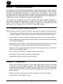
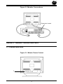
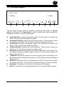
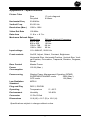
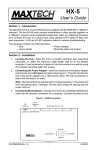
XT-7871
USER'S MANUAL
Features
•
•
•
•
•
•
•
•
•
•
Part #MAN124 Rev. 1.0
0.28 mm Dot Pitch
1280 x 1024, Non-Interlaced
120 Hz Refresh Rate
Power Saving Operation (VESA DPMS)
Anti-Static, Anti-Glare Screen
Full Screen Display
Digital Controls with OSD
Low Radiation (MPR-II)
Plug and Play
Three-Year Warranty
XT7871
Table of Contents
Section 1
Section 2
Section 3
Section 4
Appendix A
Appendix B
Appendix C
Appendix D
Appendix E
General Information ................................................... 2
Installation .................................................................. 2
Monitor Controls and LEDs ........................................ 3
Troubleshooting ......................................................... 6
Specifications ............................................................. 7
Video Cable Pinout .................................................... 8
Power Saving Modes (DPMS) .................................... 8
Three Year Warranty .................................................. 9
Notices ..................................................................... 10
IMPORTANT
• Read all these instructions. Save for later use.
• Do not expose this unit to rain or moisture.
• Do not use this unit with an extension cord or any outlet other than a three prong outlet.
• Do not open the cabinet. There are no user serviceable components inside. Refer all
servicing to a qualified technician.
• Do not cover the vent holes in the case. These are to allow for ventilation.
• Do not insert sharp objects into the monitor. They may cause accidental fire or failure.
• The socket-outlet should be installed near the equipment and should be easily accessible.
• Follow all instructions and warnings on the product.
• Do not place the product on any unstable surfaces.
• Operate from power source indicated on the label.
• Do not allow anything to rest on the power cord.
• Unplug this product from the wall outlet and refer servicing to qualified service personnel
under the following conditions:
A.
B.
C.
D.
E.
F.
When the power cord or plug is damaged or frayed.
If liquid has been spilled into the product.
If the product has been exposed to rain or water.
If the product does not operate normally when the operating instructions are
followed. Adjust only those controls that are covered by the operating instructions
since improper adjustment of the other controls may result in damage and will often
require extensive work by a qualified technician to restore the product to normal
operation.
If the product has been dropped or the cabinet has been damaged.
If the product exhibits a distinct change in performance, indicating a need for
service.
1
Section 1 - General Information
Congratulations on purchasing a MaxTech 17-inch high resolution color monitor.
The monitor uses one of the finest CRTs available in the industry. The 0.28 mm
dot pitch non-glare tube provides a crisp and vivid color display. The monitor
complies with the MPR-II standard to reduce electro-magnetic emissions. Advanced electronics and digital controls make it the perfect monitor for applications
ranging from home computing to business presentations.
The monitor is compatible with VGA, SVGA, and XGA display adapters. It
operates at resolutions ranging from 640 x 350 to 1280 x 1024 with unlimited
colors. The monitor is PnP (Plug and Play) compliant to simplify setup and
configuration in Windows 95 or other PnP operating systems.
1.1 Precautions When Using the Monitor
When setting up and using your monitor, pay special attention to the following:
• To eliminate eye fatigue, do not use your monitor against a bright background
or where sunlight or other light sources will shine directly on the monitor.
• Your monitor should be placed just below eye level for optimum viewing.
• Allow adequate ventilation around the monitor so that heat from the monitor
can properly dissipate.
• Neither the monitor itself nor any other heavy object should rest on the power
cord. Damage to a power cord can cause fire or electrical shock.
• Keep the monitor away from high capacity transformers, electric motors and
other strong magnetic fields.
• Do not use your monitor in a damp, dusty or dirty area.
• Handle the monitor with care when transporting.
• Unplug the monitor during electrical storms
Section 2 - Installation
• Plug the 15-pin male connector on the video cable into the output connector
on the rear of your computer system. The video output connector on your
computer may be either in a location similar to Figure 2-1 or on an expansion
board. Secure the cable to the computer using the thumbscrews on the 15pin connector.
• Attach the power cord to the monitor and plug it into an AC outlet.
• The monitor is now ready for use.
2
Figure 2-1 Monitor Connections
Expansion boards
COM1
COM2
LPT1
VIDEO
Section 3 - Monitor Controls and LEDs
3.1 Controls and LEDs
Figure 3-1 Master Power Control
1
3
Figure 3-2 Control and LED Locations
2
3
8
7
6
5
4
1.
Master Power (On rear): Push to provide power to the monitor. This switch
should be left ON for daily operation. Use the front panel On/Off control (3) to
turn the monitor display on and off.
2.
Power Saving Indicator: When lit, the monitor is in the DPMS OFF mode.
3.
ON/OFF: Press this switch to turn the monitor display on, press again to turn
the monitor display off.
4.
Power On Indicator: When lit the monitor is powered on
5.
Adjust: Press plus (+) to increase the setting for the selected OSD parameter. Press minus (-) to decrease the setting.
6.
Ø) to select the
Select: Press either button to enable the OSD display. Press (Ø
×) to select the previous OSD parameter.
next OSD parameter. Press (×
7.
Contrast Control: Adjusts the contrast of the display.
8.
Brightness Control: Adjusts the display brightness.
4
3.2 On-Screen Display
1280 X 1024
H: 64KHz
A
V: 60Hz
B
C
D
E
F
G
H
I
The On-Screen Display (OSD) is enabled by pressing either button of control
pair 6 (see Figure 3-2). Control pair 5 (+ and -) buttons are used to increase or
decrease the value of selected parameter.
A.
Horizontal-Size: Adjusts the display width. The (+) button increases the
width. The (-) button decreases the width.
B.
Horizontal-Position: Adjusts the horizontal position. The (+) button moves
the display to the right. The (-) button moves the display to the left.
C.
Vertical-Size: Adjusts the display height. The (+) button increases the
height. The (-) button decreases the height.
D.
Vertical-Position: Adjusts the vertical position. The (+) button moves the
display up. The (-) button moves the display down.
E.
Pincushion: Adjusts the shape of the left and right sides of the display. The
(+) button makes the display sides curve out. The (-) button makes the
display sides curve in.
F.
Trapezoid: Adjusts the shape of the left and right sides of the display. The
(+) button makes the display sides slant out. The (-) button makes the display
sides slant in.
G. Rotation: Adjusts the amount the display area will tilt. The (+) button rotates
the display clockwise. The (-) button rotates the display counter-clockwise.
H.
Degauss: Press (+) or (-) to clear color impurity of the display.
I.
Recall: Press (+) or (-) to reset parameters A-G to factory default values.
5
Section 4 - Troubleshooting
No picture, no LEDs lit.
• Check that the AC cord is plugged into an outlet and the monitor.
• Turn on the Master Power switch.
No picture, power LED is lit.
• Monitor is in DPMS STANDBY/SUSPEND mode. Press a key or move the
mouse.
• Check that video cable is connected completely.
• Adjust brightness and contrast controls.
• Check connector for bent pins.
No picture, power saving indicator (2) on.
• Monitor is in DPMS OFF mode. Press a key or move the mouse.
• Monitor is off. Press front panel On/Off switch.
• Check connector for bent pins.
Image is not centered
• Adjust Vertical Position and Horizontal Position controls.
6
Appendix A - Specifications
Picture Tube
Size
Dot pitch
17-inch diagonal
0.28mm
Horizontal Freq
30-66KHz
Vertical Freq.
50-120 Hz
Resolution (Max.)
1280 x 1024
Video Dot Rate
100 MHz
Data Area
11.8 in. x 8.7 in.
Maximum Refresh Rates
Resolution
640 x 480
800 x 600
1024 x 768
1280 x 1024
Refresh (Vertical) Frequency
120Hz
100 Hz
80 Hz
60 Hz
Input voltage
110~240VAC, 50/60 Hz
Front controls
On/Off, Adjust, Select, Contrast, Brightness
Horizontal-Size, Horizontal-Position, Vertical-Size, Vertical-Position, Pincushion, Trapezoid, Rotation, Degauss,
Recall
Rear Control
Master Power
Power
Consumption
120 W (Max.)
Power saving
Display Power Management Signaling (DPMS)
SUSPEND/STANDBY mode
20W (Max.)
OFF mode
1W (Max.)
Low Radiation
Standard
MPR-II
Plug and Play
DDC1, DDC2B
Operating
Environment
Temperature
Humidity
Connector
15 Pin D-Sub
Dimensions
16.6 (W) x 16.7 (D) x 16.6 (H)
5°~35°C
30~80%
Specifications subject to change without notice.
7
Appendix B - Video Cable Pinout
Figure B-1 Pin Layout and Pin Assignment Chart
PIN
11
6
1
10
15
5
SIGNAL
PIN
SIGNAL
1
Red
9
No Pin
2
Green
10
Ground
3
Blue
11
Ground
4
No Pin
12
SDA
5
Ground
13
Hor. Synch.
6
Red Return
14
Vert. Synch
7
Green Return
15
Data Clock
(SCL)
8
Blue Return
Appendix C - Power Saving Modes (DPMS)
VESA Display Power Management Signaling (DPMS) defines a method for a
computer to signal the monitor to reduce its power consumption when idle. DPMS
features must be supported by both the computer and the monitor. This monitor
supports DPMS “SUSPEND” “STANDBY” and “OFF” modes. Computer support
of DPMS requires the use of a DPMS compliant video card driver.
The monitor enters DPMS STAND-BY or SUSPEND mode when the computer
turns off either the Horizontal or Vertical Synchronization signal. These powersaving modes reduce the monitor’s power consumption to 20W. When the
synchronization signals are re-enabled the monitor returns to normal operation.
The monitor enters DPMS OFF mode when the computer turns off both the
Horizontal and Vertical Synchronization signals. This mode reduces the monitor’s
power consumption to 1W. When the synchronization signals are re-enabled the
monitor returns to normal operation.
8
Appendix D - Three Year Warranty
MAXTECH warrants to the original buyer of this product against defects in
material and workmanship for three years from the date of purchase.
Except as specified below, this warranty covers all defects in material or
workmanship in this product. The following are not covered by the warranty:
1. Any product which is not distributed in North America by MAXTECH or which
is not purchased in North America from an authorized MAXTECH Dealer.
2. Any product on which the serial number has been defaced, modified or
removed.
3. Damage, deterioration or malfunction resulting from:
a. Accident, misuse, abuse, neglect, fire, water, lightning or other acts of
nature, commercial or industrial use, unauthorized product modification, or
failure to follow instructions supplied with the product.
b. Repair or attempted repair by anyone not authorized by MAXTECH.
c. Any shipment of the product (claims must be presented to the carrier).
d. Removal or installation of the product.
e. Any other cause which does not relate to a product defect.
4. Cartons, carrying cases, batteries, external cabinets, magnetic tapes or any
accessories used in connection with the product.
MAXTECH will pay all labor and material expenses for covered items, but we will
not pay for the following:
1. Removal or installation charges.
2. Costs of initial technical adjustments (set-up), including adjustment of user
controls.
3. Payment of shipping charges.
HOW TO OBTAIN WARRANTY SERVICE
In the event the product requires service, call the MaxTech Service Center at (562)
921-4438 between 9:00 a.m. and 6:00 p.m. (PST Monday through Friday). When
you are instructed by the Technical Support Representative to return the product
to MaxTech for repair, you will be given an RMA (Return Merchandise Authorization) number. You must have an RMA Number to return the product for
service. Use the following procedure to return the product to MaxTech:
1.
2.
3.
4.
Return the product in its original package and packing (if possible).
Be sure to include your name, address, day-time telephone number, RMA
number, and a brief description of the problem (also enclose a check for
out-of-warranty repair).
After wrapping the package securely for shipping, print your name, return
address and the RMA # clearly on the outside of your package.
Ship the unit prepaid via UPS or the U.S. Postal Service to the address
provided by the technician when you call. We recommend that the unit be
insured.
This warranty is valid for products sold in North America only. Contact your local
authorized distributor or dealer for the warranty offered in other areas.
9
All warranty services must be performed by Authorized Service Centers. There
are no user serviceable parts inside the unit. Do not remove any components or
attempt to service the unit by any unauthorized service center. This warranty is
voided if the product has been abused, misused, modified, or repaired by an
unauthorized service center.
LIMITATION OF IMPLIED WARRANTIES
All implied warranties, including warranties of merchantability and fitness for a
particular purpose, are limited in duration to the length of this warranty.
EXCLUSION OF DAMAGES
MAXTECH'S liability for any defective product is limited to the repair or replacement of the product, at our option. MAXTECH shall not be liable for:
1. Damage to other property caused by any defects in this product, damages
based upon inconvenience, loss of use of the product, loss of time, commercial loss; or
2. Any other damages, whether incidental, consequential or otherwise.
Some states do not allow limitations on how long an implied warranty lasts and/
or do not allow the exclusion or limitation of incidental or consequential damages,
so the above limitations and exclusions may not apply to you.
HOW STATE LAW RELATES TO THE WARRANTY
This warranty gives you specific legal rights, and you may also have other rights
which vary from state to state.
Appendix E - Notices
FCC Class B Statement
This equipment has been tested and found to comply with the limits for a Class
B digital device, pursuant to Part 15 of the FCC Rules. These limits are designed
to provide reasonable protection against harmful interference in a residential
installation. This equipment generates, uses and can radiate radio frequency
energy, and if not installed and used in accordance with the instructions, may
cause harmful interference to radio communications. However, there is no
guarantee that interference will not occur in a particular installation. If this
equipment does cause harmful interference to radio or television reception, which
can be determined by turning the equipment off and on, the user is encouraged
to try to correct the interference by one or more of the following measures:
• Reorient or relocate the receiving antenna
• Increase the separation between the equipment and the receiver
• Connect the equipment into an outlet on a circuit different from that to which
10
the receiver is connected
• Consult the dealer or an experienced radio / TV technician for help
Notice: Shielded cables, if any, must be used in order to comply with the emission
limits. Any change or modification not expressly approved by the Grantee of the
equipment authorization could void the user’s authority to operate the equipment.
Canadian DOC Compliance Statement
This equipment does not exceed Class B limits for radio noise emissions for a
digital apparatus, set out in the Radio Interference Regulations of the Canadian
Department of Communications. Operation in a residential area may cause
unacceptable interference to radio and TV reception requiring the owner or
operator to take whatever steps necessary to correct the interference.
Cet équipement ne dépasse pas les limits de Class B d'émission de bruits
radioélectriques pour les appareils numériques, telles que prescrites par le
Règlement sur le brouillage radioélectrique établi par le ministère des Communications du Canada. L'exploitation faite en milieu résidentiel peut entraîner le
propriétaire ou l'opérateur à prendre dispositions nécessaires pour en éliminer
les causes.
Disclaimer, Copyright, And Other Notices
The information contained in this manual has been validated at the time of this
manual's production. The manufacturer reserves the right to make any changes
and improvements in the product described in this manual at any time and without
notice. Consequently, the manufacturer assumes no liability for damages incurred directly or indirectly from errors, omissions or discrepancies between the
product and the manual.
All registered trademarks are the property of their respective owners.
Copyright © 1997 MAXTECH. All rights reserved. No reproduction of this
document in any form is allowed without written permission from MAXTECH.
First Edition
GZ/DR - Version 1.0
11