1
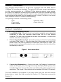
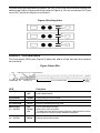
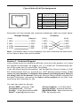
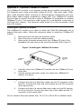
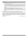
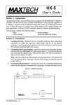
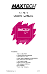
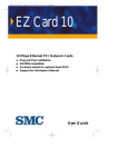
FHX-1200
Twelve-Port Stackable
Fast Ethernet Hub
User’s Guide
Part #MAN092 Rev. 1.0
LS100
Contents
Section 1 - Introduction ........................................................................ 1
Section 2 - Installation .......................................................................... 1
Section 3 - LED indicators ................................................................... 3
Section 4 - Troubleshooting .................................................................. 4
Section 5 - Specifications ..................................................................... 4
Section 6 - 100 Base-TX Cable Requirements ..................................... 4
Section 7 - Technical Support .............................................................. 5
Appendix A - Optional 100Base-FX module ........................................ 6
Appendix B - FCC Notice ...................................................................... 7
Appendix C - CE Mark Declaration of Conformance .......................... 7
Appendix D - Two Year Limited Warranty ........................................... 7
The information contained in this manual has been validated at the time of
this manual's production. The manufacturer reserves the right to make
any changes and improvements in the product described in this manual at
any time and without notice. Consequently the manufacturer assumes no
liability for damages incurred directly or indirectly from errors, omissions
or discrepancies between the product and the manual.
All registered trademarks are the property of their respective owners.
Copyright © 1996 MaxTech. All rights reserved. No reproduction of this
document in any form is allowed without written permission from MaxTech.
Section 1 - Introduction
The MaxTech FHX-1200 is a 12-port hub compliant with the IEEE 802.3u
100Base-TX fast ethernet standard. The twelve RJ-45 ports connect workstations
or other devices together on a 100Base-TX fast ethernet network using twistedpair cable. An additional crossover port connects this hub to a second hub using
a standard (straight-through) network cable for easy network expansion. The hub
also provides a stackable port for cascading up to 6 hubs (72 nodes). A full set of
LED indicators assist in network troubleshooting.
The package contains the following items:
• Hub
• Power cord
• User’s Guide
• Stacking cable
• Rack mount kit
Section 2 - Installation
2.1 Connecting Workstations to hub
1.
Locating the Hub - Place the hub in a location central to your networked
computers, or within the maximum cable length (328 ft.) to the farthest
computer. The hub may be placed on a table or mounted in a 19-inch rack
with the included mounting kit.
2.
Connecting the Power Cord - Insert the power cord into the hub’s power
connector (See Figure 1). Plug the other end of the power cord into an AC
power outlet. The hub is powered on when this connection is made. The
power switch has been eliminated to reduce the chance that the hub will be
accidentally turned off.
Figure 1 Hub connections
Fans
3.
Stackable Ports
Power
Connecting Workstations - Connect one end of a Catagory 5 twisted-pair
cable into an open port (1 through 12, except the Daisy-Chain port) on the
hub (See Figure 2). Connect the other end of the cable to the computer to be
networked. The length of the cable must be less than 328 feet (100 meters).
The hub installation is complete. If you have more than one hub and need to
daisy-chain or stack the hubs, proceed to Section 2.2. Otherwise, proceed to
Section 3.
1
Figure 2 Connecting a workstation
2.2
Connecting Hub to Hub
The network can be expanded beyond twelve workstations by connecting two or more
hubs together. There are two methods for expansion: daisy-chaining two hubs using
a twisted pair cable, or stacking up to six hubs using the hub’s stacking connector.
2.2.1 Daisy-chaining hubs
The hub’s twelfth port features an additional cross-over connection to facilitate daisychaining hubs using standard cable. Plug one end of a standard straight-through cable
(20 feet or less) into a regular port (1 through 12) of the first hub, and the other end into
the daisy-chain port of a second hub. The maximum number of hubs between any
two nodes (workstations) is two, therefore, to daisy-chain more than two hubs, link
several hubs to one central hub (refer to Figure 3).
Figure 3 Daisy-chaining hubs
Regular ports
FIRST HUB
SECOND HUB
Cross-over ports
Note: The Daisy-Chain port is port number 12 with a reversed pin-out. The daisychain port and port 12 cannot be used simultaneously.
2.2.2 Stackinging hubs
Up to six hubs may be stacked using the stacking connectors on the back of the hub.
2
Connect the supplied stacking cable to the OUT port of the first hub and connect the
cable to the IN port of the second hub (refer to Figure 4). Do not connect an OUT port
to an OUT port or an IN port to an IN port.
Figure 4 Stacking hubs
IN
OUT
IN
OUT
IN
OUT
Section 3 - LED indicators
The front-panel LEDs (see Figure 5) show the status of the hub and the network
connections.
Figure 5 Hub LEDs
COL
LINK/ACTIVITY (12) UTILIZATION (5)
PWR FX/ON FX
RJ-45 CONNECTORS
ERROR (12)
LED
DAISYCHAIN
Function
POWER
On
Off
Hub is powered on
Hub is powered off
COLLISION
Amber
Data Collision has occurred
FX/ON
Green
100 Base-FX module is installed and ON
UTILIZATION
Green
Indicates bandwidth being used
PARTITION
(1 - 12, FX)
Off
Flash
On
Port is operating normally
Data error has occurred
The port has been disconnected from the network due to excessive collisions caused by the attached computer
LINK/ACTIVITY
(1 - 12, FX)
On
Blink
A network link is established
Data is being transmitted
3
Section 4 - Troubleshooting
Symptom:
Causes:
Solution:
Symptom:
Causes:
Solution:
Symptom:
Causes:
Solution:
Partition indicator lights up.
Hub has partitioned the 100BASE-TX (RJ-45) port due to
excessive collisions.
If port partitioning has occurred, the hub will automatically
enable the port when the faulty condition disappears.
Link/Traffic indicator remains unlit.
The workstation’s network adapter, cable or the hub port is
defective.
The most common cause is a defective network adapter or
cable connection. Check the corresponding cable connections,
or the workstation’s network adapter for possible defects. Verify
that the correct cable type (straight-through catagory 5) is being
used (see Section 6). Replace the defective cable or adapter.
Port 12 and Daisy-Chain port do not work simultaneously.
Both ports are physically the same port.
Use either Port 12 or the Daisy-chain port.
Section 5 - Specifications
Network Standard:
IEEE 802.3u Ethernet 100Base-TX Class I and Class II
Repeater
Transfer rate:
100 Mbps
Topology:
Tree/Star
Access Method:
CSMA/CD, 100 Mbps
Media:
Catagory 5, 2 pair, UTP or STP
Max. cable length:
328 ft. (100 meters)
Ports:
12 RJ-45 jacks
Crossover connector: 1 RJ-45 (port 12)
Stackable connector:
SCSI II Cable connection
100Base-FX connector: SC connector (62.5/125)
Auto-partition:
Yes
Expandability:
72 ports (Class I)
Dimensions:
17.25” x 10.1” x 1.78”
Certification:
FCC Part 15 Class A
Temperature:
0° C to 55° C (operating)
Humidity:
5% to 95% (operating, non-condensing)
Power:
100-240VAC, 55 W max., 50/60 Hz
Section 6 - 100 Base-TX Cable Requirements
100Base-TX networks use unshielded or shielded twisted-pair cable and 8-pin RJ45 modular connectors. Use 22-26 AWG, 2- or 4-pair, 100 ohm/ft, solid conductor
Category 5 cable. Maximum cable length from hub to workstation is 328' (100 m).
4
Figure 6 Hub’s RJ-45 Pin Assignments
1
8
Pin
Assignment
(MDI-X Port 1 - 8)
Assignment
(MDI Daisy-Chain Port)
1
Input Receive Data +
Output Transmit Data +
2
Input Receive Data -
Output Transmit Data -
3
Output Transmit Data +
Input Receive Data +
6
Output Transmit Data -
Input Receive Data -
4,5,7,8
Not Used
Not Used
Schematics for both straight and crossover twisted-pair cable are shown below.
Straight-Through
Crossover
(Hub)
(Adapter)
(Hub)
(Hub)
1 IRD+
1 OTD+
1 IRD+
1 IRD+
2 IRD-
2 OTD-
2 IRD-
2 IRD-
3 OTD+
3 IRD+
3 OTD+
3 OTD+
6 OTD-
6 IRD-
6 OTD-
6 OTD-
Note: A crossover cable is only necessary if you are connecting two hubs which
do not have a daisy-chain port available.
Section 7 - Technical Support
In the unlikely event you experience difficulty in the use of the product, or if it does
not operate as described, we suggest you: (1) consult the Troubleshooting section of this guide and (2) consult with your dealer.
If you still cannot resolve the problem, call the MaxTech Service Center at (310)
921-4438 between 9:00 a.m. and 6:00 p.m. (PST Monday through Friday). If the
nature of your question is related to the network operating system that you
are using, refer to its manual. Calling the Service Center without complete and
accurate information concerning the nature of the problem will be both timeconsuming and frustrating for you.
You may also reach us through:
24 hour BBS - (310) 921-7180
Compuserve ID - 71333,44
Prodigy - Jump: Manufacturers BB
Email - [email protected]
24 hour Faxback - (310) 921-9540
America Online - Keyword: Maxtech
World Wide Web - www.maxcorp.com
FTP - ftp.maxcorp.com
5
Appendix A - Optional 100Base-FX module
The 100Base-FX module is an optional module which enables connectivity (as
the thirteenth port) using multi-mode duplex 62.5/125 fiber-optic cable. Fiberoptic cable provides better immunity to electromagnetic interference and supports longer cable lengths compared to copper wire. The 100Base-FX module
may be used to connect the hub to either a 100Base-FX workstation or another
100Base-FX hub. The maximum cable length for a workstation connection is
1350 feet (412 meters). The maximum cable length for a hub connection is 688
feet (210 meters).
Installing the 100Base-FX module
The 100Base-FX module is an option to allow the FHX1200 Stackable hub to
support fiber-optic cable. Follow the directions below to install the 100Base-FX
module.
1.
2.
3.
Disconnect the hub from the electrical outlet.
Place the hub on a flat and steady surface.
Remove the 4 bracket screws from the 100Base-FX port of the
stackable hub and remove the mounting bracket (See Figure 7).
Figure 7 Installing the 100Base-FX module
FHX1200
Stackable
Hub
100Base-FX
Module
4.
5.
Carefully insert the 100Base-FX module into the 100Base-FX port
of the hub.
Use the screws removed in step 3 to fasten the 100Base-FX
module into place.
Connecting cables to the 100Base-FX port
1.
2.
Connect one end of a fiber-optic cable into the TX connector of the
first hub. Connect the other end of this cable into the RX connector
of the second hub.
Connect one end of a second fiber-optic cable into the RX connector of the first hub. Connect the other end of this cable into the TX
connector of the second hub.
Do not connect fiber-optic cables from TX to TX or RX to RX on different hubs.
6
Appendix B - FCC Notice
FCC Compliance Statement
This product has been tested and found to comply with the limits for a Class B
computing device pursuant to Part 15 of the FCC rules. Installed correctly, it probably will not interfere with radio or TV reception. However, we do not guarantee the
absence of interference.
This product generates and uses energy of about the same frequency as radio
and TV broadcasts. Installed incorrectly, it may interfere with reception of radio
and TV broadcasts.
NOTE
This device complies with Part 15 of the FCC Rules. Operation is subject to the
following two conditions: (1) This device may not cause harmful interference, and
(2) this device must accept any interference received, including interference that
may cause undesired operation.
CAUTION
If the device is changed or modified without permission from MaxTech, the user
may void his or her authority to operate the equipment.
Appendix C - CE Mark Declaration of Conformance
This is to certify that this product complies with ISO/IEC Guide 22 and EN45014.
It conforms to the following specifications:
EMC:
EN55022(1988)/CISPR 22(1985)
EN60555-2(1987)
prEN55024-2(1990)/IE801-2(1991)
prEN55024-3(1991)/IE801-3(1984)
PrEN55024-4(1992)/IE801-4(1988)
Class B
Class A
4KV CD, 8KV AD
3V V/m
1KV - (power line)
0.5KV - (signal line)
This product complies with the requirements of the Low Voltage Directive 73/23/
EEC and the EMC Directive 89/336/EEC.
Appendix D - Two Year Limited Warranty
MaxTech warrants to the original buyer of this product against defects in material
and workmanship for two years from the date of purchase. During the warranty
period, MaxTech will repair (or at its option, replace) the product that proves to be
defective, provided the product has not been abused, misused, modified, or repaired by an unauthorized center.
In the event the product requires service, follow the procedure outlined in Technical Support. When you are instructed by the Technical Support Representative to
return the product to MaxTech for repair, you will be given an RMA (Return Merchandise Authorization) number. You must have an RMA Number to return the
7
product for service. Use the following procedure to return the product to MaxTech:
1.
2.
4.
5.
Return the product in its original package and packing (if possible), and put
it in a sturdy corrugated box.
Be sure to include your name, address, day-time telephone number, RMA
number, and a brief description of the problem (also enclose a check for outof-warranty repair). Enclose your check or Postal Money Order for $7.50 to
cover the cost of return shipping/handling. Please do not send cash or
stamps.
After wrapping the package securely for shipping, print your name, return
address and the RMA # clearly on the outside of your package.
Ship the unit prepaid via UPS or the U.S. Postal Service to the address
provided by the technician when you call. We recommend that the unit be
insured.
This warranty is valid for products sold in North America only. Contact your local
authorized distributor or dealer for the warranty offered in other areas.
All warranty services must be performed by Authorized Service Centers. There
are no user serviceable parts inside the unit. Do not remove any components or
attempt to service the unit by any unauthorized service center. This warranty is
voided if the product has been abused, misused, modified, or repaired by an
unauthorized service center.
First Edition
GZ/DR - Version 1.0
8