1
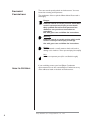
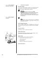
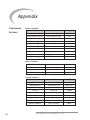
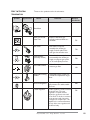
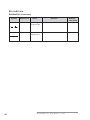
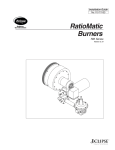
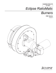
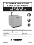
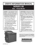
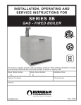
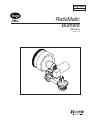
Design Guide
No.110 12/01
RatioMatic
Burners
RM Series
Version 3.10
COPYRIGHT
Copyright I998 by Eclipse Combustion, Inc. All rights reserved
worldwide. This publication is protected by federal regulation
and shall not be copied, distributed, transmitted, transcribed
or translated into any human or computer language, in any
form or by any means, to any third parties, without the
express written consent of Eclipse Combustion, Inc.,
Rockford, Illinois, U.S.A.
DISCLAIMER NOTICE
We reserve the right to change the construction and/or
configuration of our products at any time without being
obliged to adjust earlier supplies accordingly.
The material in this manual is believed adequate for the
intended use of the product. If the product, or its individual
modules or procedures, are used for purposes other than
those specified herein, confirmation of their validity and
suitability must be obtained. Eclipse Combustion, Inc. warrants
that the material itself does not infringe any United States
patents. No further warranty is expressed or implied.
We have made every effort to make this manual as accurate
and complete as possible. Should you find errors or omissions,
please bring them to our attention so that we may correct
them. In this way we hope to improve our product
documentation for the benefit of our customers. Please send
your corrections and comments to our Documentation
Manager.
LIABILITY AND
WARRANTY
It must be understood that Eclipse Combustion’s liability for
its products, whether due to breach of warranty, negligence,
strict liability, or otherwise, is limited to the furnishing of such
replacement parts and Eclipse Combustion will not be liable
for any other injury, loss, damage or expenses, whether direct
or consequential, including but not limited to loss of use,
income of or damage to material arising in connection with
the sale, installation, use of, inability to use or the repair or
replacement of Eclipse Combustion’s products.
Any operation expressly prohibited in this Guide, any
adjustment, or assembly procedures not recommended or
authorized in these instructions shall void the warranty.
2
Eclipse RatioMatic v3.10 - Design Guide No. 110, 12/01
About this manual
AUDIENCE
This manual has been written for people who are already familiar
with all aspects of a nozzle-mix burner and its add-on components,
also referred to as “the burner system.”
These aspects are:
• design/selection
• use
• maintenance.
The audience is expected to have had experience with this kind of
equipment.
RATIOMATIC
DOCUMENTS
Design Guide No. 110
• This document
RatioMatic Data Sheets, Series 110
• Available for individual RM models
• Required to complete design & selection
Installation Guide No. 110
Used with Data Sheet to complete installation
RatioMatic Price List No. 110
Used to order burners
RELATED DOCUMENTS
•
•
EFE 825 (Combustion Engineering Guide)
Eclipse Bulletins and Info Guides: 710, 732, 742, 760, 818,
832, 852, 854, 856, 610, 620, 630, 826, 820, 930, I-354.
Purpose
The purpose of this manual is to ensure that the design of a safe,
effective, and trouble-free combustion system is carried out.
Eclipse RatioMatic v3.10 - Design Guide No. 110, 12/01
3
DOCUMENT
CONVENTIONS
There are several special symbols in this document. You must
know their meaning and importance.
The explanation of these symbols follows below. Please read it
thoroughly.
Danger:
Indicates hazards or unsafe practices which WILL
result in severe personal injury or even death.
Only qualified and well trained personnel are
allowed to carry out these instructions or
procedures.
Act with great care and follow the instructions.
Warning:
Indicates hazards or unsafe pratices which could
result in severe personal injury or damage.
Act with great care and follow the instructions.
Caution:
Indicates hazards or unsafe practices which could result in
damage to the machine or minor personal injury, Act carefully.
Note:
Indicates an important part of the text. Read thoroughly.
HOW TO GET HELP
If you need help, contact your local Eclipse Combustion
representative.You can also contact Eclipse Combustion at any
of the addresses listed on the back of this document.
Eclipse RatioMatic v3.10 - Design Guide No. 110, 12/01
4
Table of Contents
About this manual . . . . . . . . . . . . . . . . . . . . . . . . . . . . . . 3
Audience . . . . . . . . . . . . . . . . . . . . . . . . . . . . . . . . . . . . . . . . 3
RatioMatic Documents . . . . . . . . . . . . . . . . . . . . . . . . . . . . 3
Related Documents . . . . . . . . . . . . . . . . . . . . . . . . . . . . . . . 3
Document Conventions . . . . . . . . . . . . . . . . . . . . . . . . . . . . 4
How to Get Help . . . . . . . . . . . . . . . . . . . . . . . . . . . . . . . . . 4
Table of Contents . . . . . . . . . . . . . . . . . . . . . . . . . . . . . . . 5
1
Introduction . . . . . . . . . . . . . . . . . . . . . . . . . . . . . . . . . . . 6
Product Description . . . . . . . . . . . . . . . . . . . . . . . . . . . . . . . 6
2
Safety . . . . . . . . . . . . . . . . . . . . . . . . . . . . . . . . . . . . . . . . . 7
Capabilities . . . . . . . . . . . . . . . . . . . . . . . . . . . . . . . . . . . . . . 8
Operator Training . . . . . . . . . . . . . . . . . . . . . . . . . . . . . . . . . 8
Replacement Parts . . . . . . . . . . . . . . . . . . . . . . . . . . . . . . . . 8
3
System Design . . . . . . . . . . . . . . . . . . . . . . . . . . . . . . . . . 9
Design . . . . . . . . . . . . . . . . . . . . . . . . . . . . . . . . . . . . . . . . . . 9
Step 1: Burner Option Selection . . . . . . . . . . . . . . . . . . . . 10
Step 2: Blower Option Selection . . . . . . . . . . . . . . . . . . . . 12
Step 3: Control Methodology . . . . . . . . . . . . . . . . . . . . . . . 13
Step 4: Ignition System . . . . . . . . . . . . . . . . . . . . . . . . . . . . 14
Step 5: Flame Monitoring Control System . . . . . . . . . . . . . 16
Step 6: Main Gas Shut-Off Valve Train . . . . . . . . . . . . . . . . . 17
Appendix . . . . . . . . . . . . . . . . . . . . . . . . . . . . . . . . . . . . . . 19
Conversion Factors . . . . . . . . . . . . . . . . . . . . . . . . . . . . . . . 19
Key to System Schematics . . . . . . . . . . . . . . . . . . . . . . . . . . 20
Eclipse RatioMatic v3.10 - Design Guide No. 110, 12/01
5
Introduction
PRODUCT DESCRIPTION
1
The RatioMatic Version 3.10 is a nozzle-mix type burner
designed for direct air heating, indirect air heating, and oven
applications up to 1800° F. (1000° C.)
The burner package includes a combustion air blower and an
air:gas ratio regulator to fire over a wide gas turndown range at
a controlled ratio.
The burner is designed for:
• efficient ratio controlled combustion
• reliable burner operation
• simple burner adjustment
• direct spark ignition
• multiple fuel capability
A wide variety of options and configurations are available due
to the modular design of the burner.
The RatioMatic Burner
6
Eclipse RatioMatic v3.10 - Design Guide No. 110, 12/01
Safety
INTRODUCTION
SAFETY
2
This section is provided as a guide for the safe operation of the
RatioMatic burner system. All involved personnel should read
this section carefully before operating this system.
Danger:
The RatioMatic burners, described herein, are
designed to mix fuel with air and burn the
resulting mixture. All fuel burning devices are
capable of producing fires and explosions if
improperly applied, installed, adjusted,
controlled, or maintained.
Do not bypass any safety feature; fire or
explosion could result.
Never try to light a burner if it shows signs of
damage or malfunction.
Warning:
The burner might have HOT surfaces. Always
wear protective clothing when approaching the
burner.
Note:
This manual provides information in the use of these burners
for their specific design purpose. Do not deviate from any
instructions or application limits described herein without
written advice from Eclipse Combustion.
Read the entire manual before attempting to start this
system. If you do not understand any part of the
information contained in this manual, contact your local
Eclipse representative or Eclipse Combustion before
continuing.
Eclipse RatioMatic v3.10 - Design Guide No. 110, 12/01
7
CAPABILITIES
OPERATOR TRAINING
REPLACEMENT PARTS
8
Only qualified personnel, with good mechanical aptitude and
experience on combustion equipment, should adjust, maintain, or
troubleshoot any mechanical or electrical part of this system.
The best safety precaution is an alert and trained operator.
Train new operators thoroughly and have them demonstrate an
adequate understanding of the equipment and its operation. A
regular retraining schedule should be administered to ensure
operators maintain a high degree of proficiency.
Order replacement parts from Eclipse Combustion only. All
Eclipse Combustion approved, customer supplied valves or
switches should carry UL, FM, CSA, CGA, and/or CE approval,
where applicable.
Eclipse RatioMatic v3.10 - Design Guide No. 110, 12/01
System Design
DESIGN
3
Design structure
The design process is divided into the following steps:
1. Burner Option Selection including:
• Burner Model / Size Selection
• Fuel Type
• Air Supply
• Combustor Type
• Combustor Length
• Control Motor
• Burner Configuration
• Gas Pipe Connection
• Flame Supervision
• Air Flow Switch
2. Blower Option Selection including:
• Power Supply Frequency
• Pressure & Flow
• Blower Motor Type
• Blower Inlet
• Motor Orientation
3. Control Methodology including:
• Burner Control
4. Ignition System including:
• Ignition Transformer
• Trial For Ignition
• Ignition Gas Piping
5. Flame Monitoring Control System including:
• Flame Sensor
• Flame Monitoring Control
6. Main Gas Shut-Off Valve Train including:
• Component Selection
• Valve Train Size
Eclipse RatioMatic v3.10 - Design Guide No. 110, 12/01
9
Step 1: Burner Option
Selection
Step 1 describes how to select burner options to suit an
application. Use the RatioMatic Price List 110 and Data Sheets,
Series 110 when following this selection process.
Caution:
Consult EFE-825, Eclipse Combustion Engineering Guide, or
contact Eclipse Combustion if you have special conditions or
questions.
Burner Model / Size Selection
Consider the following when selecting the burner size:
• Heat Input. Calculate the required heat input to
achieve the required heat balance.
• Power Supply Frequency. Burner capacity will vary
with power supply frequency (50Hz or 60Hz power).
• Combustion Chamber Pressure. Consider the
effects that large or varying chamber pressures have on
burner performance.
• Altitude. The maximum burner capacity is reduced by
approximately 3% each 1000 feet (300 meters) above
sea level.
• Combustion Air Supply. Combustion air should be
fresh (20.9% O2) and clean (without corrosives).
• Combustion Air Temperature. Changes in air supply
temperature can affect the burner capacity. The
combustion air supply temperature should not exceed
250° F.
• Fuel Type. Variation in calorific value and density will
affect burner performance.
Fuel Type
Fuel
Natural gas
Propane
Butane
Symbol
Gross Heating Value
CH4 90%+
3
(40 MJ/m )
0.60
3
3
1.52
3
1.95
C3H8
C4H10
1000 BTU/ft
2570 BTU/ft
3
3250 BTU/ft
Specific Gravity
3
(103 MJ/m )
(130 MJ/m )
3
BTU/ft @ standard conditions (MJ/m3 @ normal conditions)
If using and alternative fuel supply, contact Eclipse Combustion
with an accurate breakdown of the fuel components.
Air Supply
When a standard RatioMatic Version 3.00 burner is ordered, a
combustion air blower is supplied and mounted directly to the
burner body.
Combustor Type
Select a combustor type based on the application. Low
temperature applications use an alloy combustion tube. High
temperature applications use a silicon carbide (SiC) tube or a
refractory block & holder. For vertical down-firing
applications with block and holder, consult factory.
10
Eclipse RatioMatic v3.10 - Design Guide No. 110, 12/01
Nozzle
position
Nozzle
Combustor
Combustor
length
Configuration selections:
Combustor Length
Select a combustor length. Optional lengths are available
on some models. Nozzle position will vary with
combustor length. The nozzle position determines the
location of heat release.
Control Motor
Select a control motor. Standard control motor options
include various models which Eclipse will mount to the burner.
RatioMatics can be ordered with control motor bracket and
mounting hardware only. Customer supplied control motors
must conform to the these specifications:
• rotation not to exceed 2 rpm.
• minimum torque of 25 in-lb. (2,8 Nm)
• 90° stroke.
• continuous modulating or high/low modulating control.
• reversible direction of rotation.
• certain applications may require control motors with a
limit switch or switches if:
- the burner capacity is to be limited to fit an application.
- the chamber is to be fired with positive or negative
pressure.
- the chamber pressure is outside the range -1” w.c.
to +1” w.c. (-2,5 to 2,5 mbar)
- there is a need to indicate a high and/or low fire air
butterfly valve (BV) position.
Burner Configuration
Select configuration.
Upright
left hand piping
Inverted
left hand piping
Upright
right hand piping
Inverted
right hand piping
Gas Pipe Connection
Select the gas pipe connection including the pipe thread type and
the turndown required.
The piping, burner gas inlet, and ratio regulator are threaded
using the customer selected pipe thread option.
The high turndown option includes a ratio regulator with an
adjustment for lower inputs.
Flame Supervision
Select a flame rod or an ultraviolet (U.V.) scanner. Both are
available on all RatioMatics. If a flame rod is selected, it will be
factory mounted in the burner. If a U.V. scanner is selected, it
must be ordered separately.
Warning:
A U.V. scanner could possibly detect another
burner’s flame if it is in the line of sight, and falsely
indicate flame presence. Use a flame rod in this
situation. This helps prevent accumulation of
unburned fuel which, in extreme situations, could
Eclipse RatioMatic v3.10 - Design Guide No. 110, 12/01
11
Step 1: Burner Option
Selection (continued)
cause a fire or an explosion.
Air Flow Switch
The air flow switch provides a signal to the monitoring system
when there is not enough air pressure from the blower. If a
switch is selected, it will be factory mounted.
Warning:
Eclipse Combustion supports the NFPA
regulation requiring, as a minimum standard for
main gas shut-off systems, the use of an air
pressure switch in conjunction with other system
components.
Step 2: Blower Option
Selection
Note:
Standard blower options are listed in Price List 110, additional
blower options are available through Eclipse Combustion. Price
and leadtime may vary.
Power Supply Frequency
Select the 50Hz or 60Hz option. The 50Hz blower motors have
IEC frames and are CE marked. The 60Hz motors have NEMA
frames.
Pressure & Flow
RatioMatics include a combustion air blower.
Air
Inlet
Filter
Blower Motor Type
Motor types include various options: voltages, single or three
phase, TEFC or automotive duty enclosures.
Air flow
Switch
Right-hand
blower
motor
Blower Inlet
When selecting an inlet, consider the following:
• amount and size of particles in the air.
• sound requirements.
• space limitations.
• cleanliness requirements of the process.
Motor Orientation
12
Eclipse RatioMatic v3.10 - Design Guide No. 110, 12/01
Step 3: Control
Methodology
io
ric
on
Excess air
Gas
Air/Gas Flow
at
He
Air Butterfly
Valve (BV)
Control Motor
Ga
s F
lo
Loading Line
•
Ratio
Regulator
w
A control signal is sent from a process temperature
controller (sold separately) to the control motor. (Refer to
Bulletin 818C or contact Eclipse Combustion for further
information on temperature controllers.)
Set Point
Process
Controller
Control
Signal
Control
Motor
Process
•
•
•
Air
BV
Pressure
Impulse
Temperature
R at
a ti
St
oi
ch
io
m
et
Air
o
ol
ntr
o
c
r
pe
All RatioMatics are assembled with a right-hand blower motor
orientation.
All standard RatioMatics are designed for:
• air:gas ratio controlled combustion.
• 10% to 15% excess air at high fire.
• higher excess air at low fire
Burner Control
RatioMatics come with a ratio regulator that maintains the
air:gas ratio.
Gas Flow
Ratio
Regulator
The control motor modulates the air butterfly valve (BV)
which controls the combustion air flow.
Air pressure in the burner body sends an impulse down the
loading line to the ratio regulator.
The ratio regulator controls the gas flow in proportion to the
air flow.
Warning:
Do not use other control methods, such as, a fixed-air
control, and do not alter the ratio regulator or
burner piping without prior approval from Eclipse
Eclipse RatioMatic v3.10 - Design Guide No. 110, 12/01
13
Step 4: Ignition System
Combustion.
Ignition Transformer
For the ignition system, use a transformer with:
• secondary voltage 6,000 to 8,000 VAC.
• minimum secondary current 0.02 amps continuous.
• full wave output.
DO NOT USE the following:
• twin outlet transformer
• distributor type transformer.
Trial For Ignition
It is recommended that low fire start be used. However, under
certain circumstances RatioMatics are capable of direct spark
ignition at higher gas inputs.
Most local safety codes and insurance requirements limit the
maximum trial for ignition time (the time it takes for a burner to
ignite). These requirements vary from one location to another;
check your local codes and comply to the strictest codes
applicable.
The time it takes for a burner to ignite depends on the
following:
• the distance between the gas shut-off valve and the burner.
• the air/gas ratio.
• the gas flow conditions at start-up.
The possibility exists where the low fire is too low to ignite the
burner within the maximum trial for ignition time. The following
options must be considered under these conditions:
• start at higher gas input levels.
• resize and/or relocate the gas controls.
• use bypass start gas.
14
Eclipse RatioMatic v3.10 - Design Guide No. 110, 12/01
Step 4: Ignition System
(continued)
Ignition Gas Piping
RatioMatics are capable of ignition with either low fire or
bypass start gas.
Low Fire Start:
Main gas
shut-off
valve train
Bypass Start Gas (optional):
Main gas
shut-off
valve train
NC
Optional fuel orifice meter recommended
An optional fuel orifice meter connected in the start gas piping
can simplify start-up and adjustment. To start the burner at the
lowest possible gas input, select a fuel orifice meter for 5” to 10”
w.c. pressure drop when the gas flow is at the burner’s rated low
fire.
Eclipse RatioMatic v3.10 - Design Guide No. 110, 12/01
15
Step 5: Flame Monitoring
Control System
Flame Rod
The flame monitoring control system consists of two main
components:
• Flame Sensor
• Flame Monitoring Control
Flame Sensor
Two types can be used on a RatioMatic Burner:
• flame rod
• U.V. scanner
Flame rods are available for all RatioMatic Burner sizes. Further
information can be found in:
• Info Guide 832
U.V. Scanner
A U.V. scanner can be used on all RatioMatic Burner sizes.
Further information can be found in:
• Info Guide 852; 90° U.V. scanner
• Info Guide 854; straight U.V. scanner
• Info Guide 856; self-check U.V. scanner
Flame Monitoring Control
The Flame Monitoring Control processes the signal from the
flame rod, or U.V. scanner, and controls the start-up sequence
and the main gas shut-off valve sequence.
Eclipse Combustion recommends the use of flame monitoring
control systems which maintain a spark for the entire trial for
ignition time when using U.V. scanners. Some of these flame
monitoring models are:
• Veri-Flame; see Bulletin / Info Guide 610, 620, 630
• Bi-Flame series; see Instruction Manual 826
• Multi-Flame series 6000; see Instruction Manual 820
DO NOT USE:
• PCI Automatic flame monitoring
• Honeywell RM7890 series flame monitoring
• Flame monitoring relays which interrupt the trial for ignition
when the flame is detected.
• Flame sensors which supply a weak signal.
• Flame monitoring relays with low sensitivity.
16
Eclipse RatioMatic v3.10 - Design Guide No. 110, 12/01
Step 6: Main Gas Shut-Off
Valve Train
Component Selection
Eclipse Combustion can help in the design of a main gas shutoff valve train that satisfies the customer and complies with all
local safety standards and codes set by the authorities within
that jurisdiction. Contact Eclipse Combustion for further
information.
Note:
Eclipse Combustion supports NFPA regulations (two gas shutoff valves as a minimum standard for main gas shut-off
systems).
Valve Train Size
Fuel pressure supplied to the ratio regulator inlet must be within
the range specified in the RatioMatic data sheet. The valve train
should be sized sufficiently to provide the specified pressure.
Warning:
Do not operate RatioMatics with gas inlet
pressure less than the minimum listed on the
RatioMatic Data Sheet. Lower gas inlet pressures
may cause the ratio regulator to remain fully
open at lower inputs as the burner transitions
from low to high fire. This could result in the
possible accumulation of unburned fuel in the
burner which, in extreme situations, could cause a
fire or an explosion.
Eclipse RatioMatic v3.10 - Design Guide No. 110, 12/01
17
Appendix
CONVERSION
FACTORS
Metric to English.
From
To
Multiply By
cubic meter (m3)
cubic foot (ft3)
35.31
cubic meter/hour (m3/h)
cubic foot/hour (cfh)
35.31
degrees Celsuis (ºC)
degrees Fahrenheit (ºF)
(ºC x 1.8) + 32
kilogram (kg)
pound (lb)
2.205
kilowatt (kW)
BTU/hr
3414
meter (m)
foot (ft)
3.28
millibar (mbar)
inches water column (“w.c.)
0.401
millibar (mbar)
pounds/sq in (psi)
14.5 x 10⁻³
millimeter (mm)
inch (in)
3.94 x 10⁻²
MJ/m3 (normal)
BTU/ft3 (standard)
2.491 x 10⁻²
kiloPascals (kPa)
millibar (mbar)
10
meter (m)
millimeter (mm)
1000
millibar (mbar)
kiloPascals (kPa)
0.1
millimeter (mm)
meter (m)
0.001
From
To
Mulitply By
BTU/hr
kilowatt (kW)
0.293 x 10⁻³
cubic foot (ft3)
cubic meter (m3)
2.832 x 10⁻²
degrees Fahrenheit (ºF)
degrees Celsius (ºC)
(ºF – 32) ÷ 1.8
foot (ft)
meter (m)
0.3048
inches (in)
millimeter (mm)
25.4
inches water column (“wc)
millibar (mbar)
2.49
pound (lb)
kilogram (kg)
0.454
pounds/sq in (psi)
millibar (mbar)
68.95
Metric to Metric.
English to Metric.
3
BTU/ft (standard)
18
3
MJ/m (normal)
Eclipse RatioMatic v3.10 - Design Guide No. 110, 12/01
40.14
KEY TO SYSTEM
SCHEMATICS
Symbol
Appearance
These are the symbols used in the schematics.
Name
Remarks
Bulletin/
Info Guide
RatioMatic
NC
Main Gas Shutoff
Valve Train
Eclipse Combustion, Inc.
strongly endorses NFPA as a
minimum
Gas Cock
Gas cocks are used to
manually shut off the gas
supply on both sides of the
main gas shut-off valve train.
710
Solenoid Valve
(normally closed)
Solenoid valves are used to
automatically shut off the gas
supply on a bypass gas system
or on small capacity burners.
760
Fuel Orifice Meter
Fuel orifice meters are used to
measure gas flow.
Adjustable Limiting
Orifice
Adjustable limiting orifices are
used for fine adjustment of gas
flow.
Pressure Regulator
A pressure regulator reduces
gas pressure to a stable, usable
pressure.
Ratio Regulator
A ratio regulator is used to control
the air/gas ratio. The ratio
regulator is a sealed unit that
adjusts the gas flow in ratio with
the air flow. To do this, it measures
the air pressure with a pressure
sensing line, the impulse line. This
impulse line is connected between
the top of the ratio regulator and
the burner body.
Eclipse RatioMatic v3.10 - Design Guide No. 110, 12/01
756
910
684
742
19
KEY TO SYSTEM
SCHEMATICS (CONTINUED)
Symbol
Appearance
Name
Remarks
Pressure Taps
Impulse Line
20
Eclipse RatioMatic v3.10 - Design Guide No. 110, 12/01
Bulletin/
Info Guide
Offered By:
Power Equipment Company
2011 Williamsburg Road
Richmond, Virginia 23231
Phone (804) 236-3800
Fax (804) 236-3882
www.peconet.com