1
Installation Guide 248
4/10/07
E clipse Vortometric
Burners
yyyy
;;;;
;;;;
yyyy
;;;;
yyyy
;;;;
yyyy
COPYRIGHT
Copyright 1997 by Eclipse Combustion. All rights reserved worldwide.
This publication is protected by federal regulation and shall not be
copied, distributed, transmitted, transcribed or translated into any
human or computer language, in any form or by any means, to any third
parties, without the express written consent of Eclipse Combustion.
DISCLAIMER NOTICE
In accordance with the manufacturer’s policy of continual product
improvement, the product presented in this brochure is subject to
change without notice or obligation.
The material in this manual is believed adequate for the intended use of
the product. If the product is used for purposes other than those
specified herein, confirmation of validity and suitability must be
obtained. Eclipse Combustion warrants that the product itself does not
infringe upon any United States patents. No further warranty is
expressed or implied.
We have made every effort to make this manual as accurate and
complete as possible. Should you find errors or omissions, please bring
them to our attention so that we may correct them. In this way, we
hope to improve our product documentation for the benefit of our
customers. Please send your corrections and comments to our
Marketing Communications Manager.
LIABILITY AND
WARRANTY
ii
It must be understood that Eclipse Combustion’s liability for its
products, whether due to breach of warranty, negligence, strict liability,
or otherwise, is limited to the furnishing of replacement parts and
Eclipse Combustion will not be liable for any other injury, loss, damage
or expenses, whether direct or consequential, including but not limited
to loss of use, income of, or damage to material arising in connection
with the sale, installation, use of, inability to use or the repair or
replacement of Eclipse Combustion’s products.
Eclipse Vortometric Burner v2.00, Installation Guide 248, 4/10/07
About this manual
AUDIENCE
This manual has been written for those persons who are already familiar
with all the aspects of a burner and its add-on components, also referred
to as “the burner system”. These aspects are:
• design/selection
• installation
• use
• maintenance
The audience is expected to have previous experience with this kind
of equipment.
SCOPE
This manual provides information for installing the Vortometric
burner ONLY and does not include the burner control system
(such as fuel/air ratio controls, flame supervision systems, etc.).
When Eclipse Combustion sells the burner as part of a complete
package, then schematic piping and wiring diagrams will be furnished
which explain the control system operation. When Eclipse
Combustion sells only the Vortometric burner, then it is the
purchaser’s responsibility to ensure that:
• the control system is adequate for the application,
• the control system meets all applicable codes and regulations, and
• the operating personnel are fully familiar with safe control system
operation.
VORTOMETRIC
PUBLICATIONS
Installation Guide No. 248
• This publication.
Data Sheets No. 248-1, 248-2
• Lists burner models information including dimensions.
Bulletin No. 248
• Used with Data Sheets to define burner specifications and
available options.
Price Sheet No. 248
• Used to order burners.
Eclipse Vortometric Burner v2.00, Installation Guide 248, 4/10/07
iii
RELATED PUBLICATIONS
• EFE-825 (Combustion Engineering Guide)
• Eclipse Bulletins & Instruction Manuals: 818, 820, 826, 832, 852, 854, 856
IMPORTANT NOTICES
• Read this manual carefully. Make sure that you understand the structure
and contents of this manual.
• Obey all the safety instructions.
• Do not deviate from any instructions or application limits in this
manual without written consent from Eclipse Combustion.
• If you do not understand any part of the information in this manual, do
not continue. Contact your Eclipse sales office or Eclipse Combustion.
DOCUMENT
CONVENTIONS
There are several special symbols in this document.You must know
their meaning and importance.
The explanation of these symbols follows. Please read it thoroughly.
Danger:
Indicates hazards or unsafe practices which WILL
result in severe personal injury or even death.
Only qualified and well trained personnel are
allowed to carry out these instructions or
procedures.
Act with great care and follow the instructions.
Warning:
Indicates hazards or unsafe practices which could
result in severe personal injury or damage.
Act with great care and follow the instructions.
Caution:
Indicates hazards or unsafe practices which could result in
damage to the machine or minor personal injury.
Act carefully.
Note:
Indicates an important part of the text.
Read the text thoroughly.
iv
Eclipse Vortometric Burner v2.00, Installation Guide 248, 4/10/07
Table of Contents
1
About this manual ................................................................
ii
Table of Contents ..................................................................
v
Introduction ...............................................................................
1-1
1-1
Product Description ........................................................................
2
Safety ...............................................................................................
Introduction .......................................................................................
Safety ...................................................................................................
Capabilities .........................................................................................
Operator Training .............................................................................
Replacement Parts ...........................................................................
3
Installation ..................................................................................
Introduction .......................................................................................
Handling and Storage .......................................................................
Position of Components .................................................................
Approval of Components ...............................................................
Limits controls and safety equipment .....................................
Electrical wiring ............................................................................
Gas piping ......................................................................................
Where to get the standards ......................................................
Checklist before Installation ..........................................................
Burner Mounting ..............................................................................
Prepare the Burner ..........................................................................
Gas, Gas/Oil or Oil Gun Positioning .......................................
Install the flame sensor ...............................................................
Pilot .................................................................................................
Piping ...............................................................................................
Strainers .........................................................................................
Atomizing Control Methods .....................................................
Installing and Curing Refractory Block .......................................
Checklist after Installation .............................................................
Eclipse Vortometric Burner v2.00, Installation Guide 248, 4/10/07
2-1
2-1
2-1
2-2
2-2
2-2
3-1
3-1
3-1
3-1
3-2
3-2
3-2
3-2
3-2
3-3
3-4
3-2
3-2
3-7
3-8
3-8
3-10
3-10
3-11
3-14
v
4
Adjustment, Start & Stop ..............................................
Introduction .......................................................................................
Adjustment Procedure ....................................................................
Step 1: Reset the system ..........................................................
Step 2: Set low fire combustion air pressure drop ...........
Step 3: Verify air settings ..........................................................
Step 4: Ignite the pilot ...............................................................
Step 5: Ignite the burner ..........................................................
Step 6: Adjust low fire ...............................................................
Step 7: Adjust high fire ..............................................................
Step 8: Verify settings .................................................................
Start Procedure ................................................................................
Stop Procedure .................................................................................
5
Maintenance & Troubleshooting ...............................
Introduction .......................................................................................
Maintenance Schedules ...................................................................
Monthly Checklist ........................................................................
Yearly Checklist ............................................................................
Maintenance Procedures ................................................................
Fuel Oil Tip Cleaning ...................................................................
Dismantling of Atomizer ............................................................
Assembly of Atomizer.................................................................
Troubleshooting ................................................................................
Appendix ......................................................................................
4-1
4-1
4-1
4-1
4-2
4-2
4-2
4-3
4-4
4-5
4-5
4-6
4-7
5-1
5-1
5-1
5-1
5-2
5- 2
5- 2
5-4
5-6
5-8
A-1
Flow and Input Charts .................................................................... A-1
Table A.1– Combustion Air Pressure Drop vs. Burner Heat Input
for Medium Intensity Burners ................................................... A-1
Table A.2– Combustion Air Pressure Drop vs. Burner Heat Input
for High Intensity Burners ......................................................... A-2
Table A.3–Gas Gun Press. Drop vs. Burner Heat Input ..... A-3
Table A.4– Oil Nozzle Press. Drop vs. Burner Heat Input .... A-4
Table A.5– Atomizing Air Press. Drop vs. Air Flow ............... A-4
Table A.6– Atomizing Steam Press. Drop vs. Steam Flow ..... A-5
Recommended Spare Parts ............................................................ A-5
Conversion Factors ......................................................................... A-6
System Summary .............................................................................. A-7
vi
Eclipse Vortometric Burner v2.00, Installation Guide 248, 4/10/07
Introduction
PRODUCT
DESCRIPTION
1
The Eclipse Vortometric v2.00 is a dual-fuel, high intensity burner
which operates at maximum efficiency whether firing fuel oils or
natural, propane, butane, manufactured or other mixed gases.
The Vortometric’s versatility and rugged design make it the right
choice for any heating process, including driers, kilns, thermal fluid
heaters, thermal oxidizers, oil heaters, vaporizers, boilers, liquid and
waste incineration, and many air heating applications.
The high combustion air swirl rate produced by the Vortometric
burner results in a stable flame with high turndown capabilities on a
wide range of fuels. The burner can be operated with low excess air
where maximum efficiency is required or high excess air for high
volume process air heating. The intense and thorough mixing of the
air and gas results in low NOx and CO emissions.
The novel design of the oil atomizer uses shear forces and
acoustical energy created by a “vortex generator” to vaporize the
fuel for clean, smoke-free combustion.
Vortometric v2.00 burners are available with capacities of 6mmBtu/
hr. to 210mmBtu/hr. Low combustion air pressure is used (7.5"w.c.)
with all sizes and atomization of the fuel oil can be by steam, air, or
any gaseous fuel.
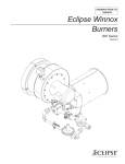
Figure 1.1 Vortometric v2.00 Burner
yyyy
;;;;
;;;;
yyyy
;;;;
yyyy
;;;;
yyyy
Eclipse Vortometric Burner v2.00, Installation Guide 248, 4/10/07
1-1
Eclipse Vortometric Burner v2.00, Installation Guide 248, 4/10/07
Safety
INTRODUCTION
SAFETY
2
In this section, you will find important notices about safe operation
of a burner system.
Danger:
The burners covered in this manual are designed
to mix fuel with air and burn the resulting
mixture. All fuel burning devices are capable of
producing fires and explosions when improperly
applied, installed adjusted, controlled, or
maintained.
Do not bypass any safety feature.
You can cause fires and explosions.
Never try to light the burner if the burner shows
signs of damage or malfunctioning.
Warning:
The burner and duct sections are likely to have
HOT surfaces. Always wear protective clothing
when approaching the burner.
Note:
This manual gives information for the use of these burners
for their specific limited design purpose. Do not deviate from
any instructions limits in this manual without written advice
from Eclipse Combustion.
Note:
Read this entire manual before you attempt to start the
system. If you do not understand any part of the information
in this manual, then contact your Eclipse representative or
Eclipse Combustion before you continue.
Eclipse Vortometric Burner v2.00, Installation Guide 248, 4/10/07
2-1
CAPABILITIES
Adjustment, maintenance and troubleshooting of the mechanical and the
electrical parts of this system should be done by qualified personnel with
good mechanical aptitude and experience with combustion equipment.
OPERATOR TRAINING
The best safety precaution is an alert and competent operator.Thoroughly
instruct new operators so they demonstrate an adequate understanding
of the equipment and its operation. Regular retraining must be scheduled
to maintain a high degree of proficiency.
REPLACEMENT PARTS
Order replacement parts from Eclipse only.Any customer-supplied
valves or switches should carry UL, FM, CSA, CGA and/or CE approval
where applicable.
2-2
Eclipse Vortometric Burner v2.00, Installation Guide 248, 4/10/07
Installation
3
INTRODUCTION
In this section you will find the information and instructions that you
need to install the burner.
HANDLING AND
Handling
STORAGE
1. Make sure that the area is clean.
2. Protect the components from the weather, damage, dirt and
moisture.
3. Protect the components from excessive temperatures and humidity.
4. Take care not to drop or hit components.
Storage
1. Make sure that the components are clean and free of damage.
2. Store the components in a cool, clean, dry room.
3. After you have made sure that everything is present and in good
condition, keep the components in the original package as long
as possible.
Caution:
When the refractory combustion block is supplied with the
burner, it is critical that the instructions for handling and storage
are followed. The refractory should be considered fragile;
improper handling and storage will cause premature failure.
Eclipse Vortometric Burner v2.00, Installation Guide 248, 4/10/07
3-1
APPROVAL OF COMPONENTS
Limit controls and safety
equipment
All limit controls and safety equipment must comply with the following
current standards:
•
•
•
•
•
•
•
•
Electrical wiring
All of electrical wiring must comply with the one of the following
standards:
•
•
•
•
•
Gas piping
NFPA Standard 70
ANSI-C11981
CSA
EN 746-2
the electrical wiring must be acceptable to the local authority having
jurisdiction.
All of the gas piping must comply with the one of the following
standards:
•
•
•
•
Where to get the standards
NFPA Standard 86
NFPA Standard 86C
UL
FM
CGA
CSA
EN 746-2
all applicable local codes and/or standards.
NFPA Standard 54
ANSI Z223
EN 746-2
the gas piping must be acceptable to the local authority having
jurisdiction.
The NFPA Standards are available from:
National Fire Protection Agency
Batterymarch Park
Quincy, MA 02269
The ANSI Standards are available from:
American National Standard Institute
1430 Broadway
New York, NY 10018
The UL Standards are available from:
United Laboratories
333 Pfingsten Road
Northbrook, IL 60062
3-2
Eclipse Vortometric Burner v2.00, Installation Guide 248, 4/10/07
The FM Standards are available from:
Factory Mutual
1151 Boston-Providence Turnpike
P.O. Box 9102
Norwood, MA 02062
The CGA Standards are available from:
Canadian Gas Association
55 Scarsdale Road
Toronto, Ontario
Canada M3B 2R3
The CSA Standards are available from:
Canadian Standards Association
178 Rexdale Boulevard
Etobicoke, Ontario
Canada M9W 1R3
Information on the EN standards, and where to get the standards is
available from:
Comité Européen de Normalisation
Stassartstraat 36
B-1050 Brussels
Phone: +32-25196811
Fax: +32-25196819
Comité Européen de Normalisation Electronique
Stassartstraat 36
B-1050 Brussels
Phone: +32-25196871
Fax: +32-25196919
CHECKLIST BEFORE
Access
INSTALLATION
Make sure that you install the system in such a way that you can get
easy access to the burner for inspection and maintenance.
Environment
Make sure that the local environment matches the original operating
specifications. Check the following items:
•
•
•
•
•
voltage, frequency and stability of the electrical power
type and supply pressure of the fuel
availability of enough fresh, clean combustion air
humidity, altitude and temperature of air
presence of damaging corrosive gases in the air.
Eclipse Vortometric Burner v2.00, Installation Guide 248, 4/10/07
3-3
BURNER MOUNTING
Depending on your application, please keep the following in mind
when mounting a burner:
• Ensure that the burner is level and that the furnace or burner
casing has sufficient rigidity to support the burner. If necessary,
provide stiffeners on the casing or supports under the burner.
• Remember to compensate for the burner’s combustor liner
extension for the refractory combustion block.
• Use gasketing between the burner mounting flange and the
furnace casing and ensure that you have a gas-tight joint between
these two surfaces. This tightness is especially critical for systems
operating under positive pressures.
PREPARE THE BURNER
There are several components that must be installed to a burner
systems before it can operate. Instructions to do that follow below.
Gas, Gas/Oil or Oil Gun
Positioning
Prior to starting the burner, the gun position in relation to the
burner throat cone must be checked.
Note:
Burners are not necessarily shipped with guns in the correct
position; it is also possible that the gun could shift during shipment.
Note:
All of the following adjustments provide a relative position for
safe operation for all applications; occasionally, adjustments in or
out from the relative positions may be necessary depending on
your application.
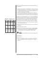
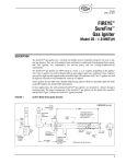
For Gas Only Burners (see Figure 3.1):
1. To adjust the gas gun, loosen the gland.
2. Using the chart in Figure 3.1, determine the “X” dimension
based on your burner size.
3. Once the “X” dimension is verified and the gas gun is centered
in relation to the throat cone, tighten the gland.
Note:
Failure to center the gun in the burner throat will cause uneven
air flow and flame instability. The gun should be centered with
+/- 1/8".
3-4
Eclipse Vortometric Burner v2.00, Installation Guide 248, 4/10/07
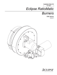
Figure 3.1 Vortometric Gas Gun Position
4
5
Burner
Size
“X”
(Inches)
6V
8V
10V
12V
11/16
1-3/8
1-5/16
1-1/2
14V
16V
18V
22V
1-11/16
2-1/16
2
2-5/16
24V
28V
32V
36V
2-1/4
3-3/16
3-1/16
3-7/8
Gland
To Adjust
Gun Position
3
2
1 Gas Inlet
2 Gas Gun
3 Throat Cone
“X”
Dim.
1
4 Air Inlet
5 Refractory Block Walls
5
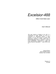
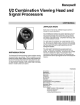
Figure 3.2 Vortometric Gas/Oil Gun Position
7
8
Gland “B”
Used to adjust the position
of entire gun assembly
within burner throat
6
2
5
1
1
2
3
4
5
3
Gland “A”
Used to adjust the position
of oil gun within gas gun.
End of
oil atomizer
is flush with
throat cone ring
Oil Inlet
Oil Gun
Steam/Air Inlet
Gas Inlet
Gas Gun
6 Throat Cone
7 Air Inlet
8 Refractory Block Walls
4
8
Eclipse Vortometric Burner v2.00, Installation Guide 248, 4/10/07
3-5
For Combination Gas/Oil Burners–Initial Adjustment (see
Figure 3.2):
1. Adjust the oil gun position by loosening gland “A”.
2. Align the conical faces of the oil and gas guns.
3. Once both guns are aligned, tighten gland “A” on the oil gun.
Note:
After this initial adjustment, all subsequent adjustments for
combination gas/oil burners require that both guns be moved as
a single unit.
For Combination Gas/Oil Burners–Subsequent Adjustments
(see Figure 3.2):
1. Adjust the entire gas/oil gun assembly by loosening gland “B”.
2. Move the entire gun assembly until the oil nose cone aligns with
the small diameter of the throat cone.
3. Once both cones are aligned and the gas gun is centered in
relation to the throat cone, tighten gland “B”.
For Oil Only Burners (see Figure 3.2):
1. Adjust the oil gun position so that the end of the oil nose cone
aligns with the small diameter of the throat cone as shown at left.
2. Verify that the oil gun is centered in relation to the throat cone;
once verified, tighten the large gland nuts.
Note:
Failure to center the gun in the burner throat will cause uneven
air flow and flame instability. The gun should be centered with
+/- 1/8".
3-6
Eclipse Vortometric Burner v2.00, Installation Guide 248, 4/10/07
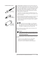
Install the flame sensor
U.V. Scanner
(Model 5600-91)
An ultraviolet flame sensing device, or U.V. scanner, must be used
with a 3/4" N.P.T. swivel connector. The scanner and connector can
be used in three possible locations: two mounting ports are located
near the gun assembly adjacent to the pilot which sight both pilot
and main flames, while a third mounting port on the side of the
combustor sights only the main flame. Flame detection methods
are affected by fuels and applications:
• For gas, light oil, or heavy oil with air atomization, locate a U.V.
scanner in one of the two mounting ports near the pilot to prove
pilot and main flames.
90° U.V.
Scanner
(Model 5600-90A)
Self-Check
U.V. Scanner
(Model 5602-91)
• For heavy oil with steam atomization, two scanners must be used.
Because atomizing steam absorbs ultraviolet light, a scanner
mounted near the pilot will only prove the pilot flame. Therefore,
a second scanner mounted on the combustor side is needed to
prove the main flame.
Note:
Due to the low U.V. content of oil flames, some U.V. scanner/
flame safety systems may have difficulty sighting oil flames at
high inputs. In these cases, a more sensitive U.V. detector may
be required or an infrared (I.R.) detector may be used.
Make sure that you connect the flame sensor of a burner to the
electrical circuit of the burner.
Danger:
If you connect the flame sensor of a burner to the
electrical circuit of the wrong burner, then you can
cause fires and explosion.
For detailed information on how to install and connect a U.V. scanner,
refer to:
• straight U.V. scanner; Bulletin/Instruction Manual 854
• 90° U.V. scanner; Bulletin/Instruction Manual 852
• self-check U.V. scanner; Bulletin/Instruction Manual 856.
Eclipse Vortometric Burner v2.00, Installation Guide 248, 4/10/07
3-7
Pilot
Pilot ignition
The standard Vortometric spark-ignition pilot requires an ignition
transformer with a minimum of 6000 volt secondary. Mount the
transformer in a location where it will not overheat while allowing
as short an ignition lead as possible.
Pilot assembly positioning
The relation of the pilot assembly to the main burner gun affects air
flow through the throat cone. Therefore, it is important that the pilot
be as far away as possible from the throat cone while maintaining
reliable ignition. For initial start-up, the pilot assembly should be
between 6" and 8" away from throat cone; if necessary, adjust the
pilot assembly gland to achieve this distance.
Piping
Support the piping and ductwork
Use brackets or hangers to support the piping and ductwork to
avoid placing undue loads on the burner. If you have questions,
consult your local gas company.
Pipe connections
The use of flexible pipe in gas, oil and atomizing air lines to the
burner is recommended. Adjustments of the main gas, pilot gas and
oil guns may be required during burner setup.
Avoid large pressure drops
Note:
The pressure drop of the gas in the piping is a critical
parameter. Make sure that the size of all the piping is large
enough to prevent excessive pressure losses.
3-8
Eclipse Vortometric Burner v2.00, Installation Guide 248, 4/10/07
Oil fuel considerations
1. In heavy oil (#5 or #6) applications, the oil temperature at the
burner inlet should be 220° to 270°F for good viscosity
(maximum 150 SSU). Depending on burner location, steam or
electric tracing AND pipe insulation are usually needed to
ensure this oil temperature range. Other oils (wastes, residues,
etc.), may also require similar provisions to ensure good
viscosity.
2. Foreign material can easily clog the small injection holes in the oil
nozzle tip. Therefore, ensure that all inside surfaces of assembled
piping to the burner are free of dirt, grit, shavings or any other
foreign material. To avoid contamination, use thread sealants such
as Teflon paste only on pipe threads that will not come in contact
with the oil flow.
3. A purge of the oil nozzle should be conducted after burner
shutdown. To do so, connect a line between the atomizing
medium and the oil piping just upstream of the oil nozzle, and
install check valves in this line and the oil piping.
Atomizing steam considerations
1. Atomizing steam must be dry and superheated to at least 20°F
above saturated at the burner inlet. Therefore, this piping line must
be insulated up to the burner inlet. Provisions must also be made
for continuous condensate disposal via a steam trap and drain.
Compressed air considerations
1. When compressed air is used for atomization, it is possible for
water and oil vapor from the air compressor to contaminate the
atomizer. Therefore, include preventative measures against this
possibility when designing the air distribution system.
2. ALL compressors should be equipped with a suitable aftercooler,
oil separator, and automatic traps or drain valves.
3. When compressed air is used for atomization of heavy oils (#5
or #6), preheat the air to a temperature between 220° and
270°F and insulate the air lines.
Pilot gas considerations
1. ALL supplied gas pilot piping (natural, propane, etc.) MUST be
fitted with a pilot gas pressure regulator.
2. ALL supplied gas pilot piping (natural, propane, etc.) SHOULD BE
fitted with an adjustable orifice valve for pilot gas flow adjustment.
Eclipse Vortometric Burner v2.00, Installation Guide 248, 4/10/07
3-9
Strainers
No matter what fuel is used, it is essential that the valve train
components, the atomizer and the fuel oil tip be protected from
foreign material damage. Therefore, it is suggested that strainers be
used as follows:
Oil valve trains
1. It is recommended that an edgeplate type filter with 0.0035"
separations (170 mesh) be used UPSTREAM of all valve train
components.
2. It is recommended that a strainer with 100 mesh screen be used
ADJACENT to the oil gun inlet.
Atomizing valve trains
It is recommended that a strainer with 1/32" diameter perforated or
20 mesh screen be used UPSTREAM of all valve train components
for steam or compressed air applications.
Fuel gas valve trains
It is recommended that a strainer with 1/32" diameter perforated or
20 mesh screen be used UPSTREAM of all valve train components.
Atomizing control methods
There are two possible control methods for atomizing air and steam:
1. Fixed: If the burner’s turndown ratio requirement does not
exceed 5:1, then the atomizing pressure at the burner may be
set to run constantly at 50/55 psig, eliminating the need for a
differential pressure regulator.
2. Modulating: Use a differential pressure regulator which is “top
loaded” with the oil pressure at the nozzle, which allows the
atomizing pressure to increase proportionally with the oil
pressure. To do so, set the atomizing pressure approximately 20
psig above the oil pressure, but not exceeding 50/55 psig. To
ensure this maximum pressure is not exceeded, adjust the
pressure regulator for the incoming atomizing supply to not
exceed 50/55 psig.
3-10
Eclipse Vortometric Burner v2.00, Installation Guide 248, 4/10/07
INSTALLING AND
CURING REFRACTORY
BLOCK
It is the customer’s choice whether the combustion refractory
block is factory or field installed. The following provisions deal with
installing either choice. The standard, general purpose refractory
for Vortometric combustor blocks is Plibrico 80 Air Bond with an
80% alumina plastic ramming mix.
Factory installed refractory
The Eclipse factory installed refractory has been oven cured at
relatively low temperatures to remove most of the water content.
However, some residual water may still be present and must be
removed at the initial start-up.
After the burner and refractory have been installed, the following
steps will ensure proper curing and maximum strength to reduce
chances of cracking or spalling:
1. Set the combustion air at its minimum input.
2. Light only the pilot and leave on for approximately three hours.
3. After three hours, light the main burner at the minimum input.
4. Increase the heat input by 150°F per hour.
5. Water evaporation (steam) is usually heaviest and most
prominent around 1,000°F. If steam is still prevalent after the
hour at 1,000°F, hold at that temperature for two to three more
hours or until the steam stops.
Caution:
If at anytime during the curing process visible steam rises from
the refractory, hold the temperature until it dissipates.
6. Once steam stops coming from the refractory, assume the 150°F
temperature rise per hour until you reach 2,000°F.
7. Hold at 2,000°F for three to four hours to ensure proper curing.
Eclipse Vortometric Burner v2.00, Installation Guide 248, 4/10/07
3-11
Field installed refractory
The customer is responsible for supplying all refractory materials
for field installation as follows:
1. Cover the inside surfaces of the combustor shell with an 1/8"
layer of Plibrico “Plisulate” fibrefax paper or equivalent.
2. Install alloy anchors in the combustor shell according to the
refractory supplier’s recommendations. The alloy anchors should
be coated with bitumastic wherever they protrude through the
layer of Plibric Plisulate.
3. Install the chosen refractory, realizing it is essential that:
• the combustion block dimensions are held as given on Eclipse
drawings
• the inside diameter of the combustion block be concentric
with the air cone in the burner.
Refer to Figure 3.3 for wall interface, and typical refractory
installation details and recommendations.
4. The refractory should then be pounded into place with a
pneumatic rammer, starting around the air cone. Use care in
ensuring that the specified contours and dimensions on the
aforementioned Eclipse drawing are maintained. Provide vent
holes so moisture can escape during dry-out.
Note:
The corner angle between the cone and the sidewall must be
90° or slightly less, but NOT MORE.
After the burner and refractory have been installed, the following
steps will ensure proper curing and maximum strength to reduce
chances of cracking or spalling:
1. Set the combustion air at its minimum input.
2. Light only the pilot and leave on for approximately three hours.
3. After three hours, light the main burner at the minimum input.
4. Increase the heat input by 100°F per hour.
5. Water evaporation (steam) is usually heaviest and most
prominent around 1,000°F. If steam is still prevalent after the
hour at 1,000°F, hold at that temperature for two to three
more hours or until the steam stops.
Caution:
If at anytime during the curing process visible steam rises from
the refractory, hold the temperature until it dissipates.
6. Once steam stops coming from the refractory, assume the 100°F
temperature rise per hour until you reach 2,000°F.
7. Hold at 2,000°F for three to four hours to ensure proper curing.
3-12
Eclipse Vortometric Burner v2.00, Installation Guide 248, 4/10/07
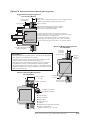
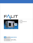
Figure 3.3 Vortometric Burner Mounting Arrangements
Suggested Mounting Arrangement
For Standard Burner
229mm (9")*
Flange position on standard burner allows correct shell dimension above
*178mm (7") for 6V and 8V medium intensity burner sizes.
Provide adequate
shell stiffeners
Furnace backstay
Furnace shell plate
Weld heads of mounting bolts inside furnace shell plate.
Allow for 3mm (1/8") thick, high temperature gasket
between the burner flange and shell plate.
90 hold
Ring
Smooth refractory
flush with throat
To allow for thermal expansion of combustion liner extension,
the main wall should be constructed with an opening 25mm (1") greater
in diameter than diameter of combustion liner.
The outside of combustion liner should be covered with 1/8" thick
insulating paper. The remaining gap between the burner and main wall
should be densely packed with ceramic fiber or wool blanket insulation.
Alternate Mounting Arrangement
For Thin Walls
3mm (1/8") high temp. gasket
(Customer supplied)
152mm (6")
minimum
for standard
burner mounting
General Notes:
76mm (3")
maximum
projection
1. Mounting illustrations show typical Vortometric combustor blocks of high alumina
plastic refractory as used by Eclipse for normal duty.
2. The dimensions given must be held as specified, and the inner diameter of the
combustor must be round and concentric with the throat cone.
3. Alloy rod-type anchors welded inside the combustor block are the customer’s
responsibility if the refractory is field installed rather than factory installed.
4. All mounting arrangements are meant for vertically or horizontally fired burners.
Regardless of orientation, the refractory block MUST be protected from thermal
expansion of the furnace wall.
Alternate Mounting Arrangement
For Thick Walls
229mm to 457mm
(9" to 18")
2
1 34
5
6
7
Main flame
scanner
229mm (9") minimum
Burner mounting
box by customer
Cup angle or special anchor
fitting welded to shell plate
1 Furnace Backstay
30
2 Furnace Shell Plate
3 Block Insulation
4 Insulated Fire Brick
5 Fire Brick
6 Castable Refractory Ring (Alternate Plastic)
7 Refractory or Alloy Anchor
(305mm to 457mm or 12" to 18" apart)
Eclipse Vortometric Burner v2.00, Installation Guide 248, 4/10/07
3-13
CHECKLIST AFTER
INSTALLATION
To make sure that the system is installed correctly, do the steps that
follow:
1. Make sure that there are no leaks in the gas lines.
2. Make sure that the blower rotates in the correct direction. If
incorrect, then have a qualified electrician rewire the blower to
reverse its rotation.
3. Set the air proving switch.
4. Set the low gas pressure switch.
5. Set the high gas pressure switch.
6. Close all the burner gas cocks.
7. Trip out pressure switches and other limit interlocks. Make sure
that the main gas valves close.
Danger:
If simulated limits or simulated flame failures do
not shut down the fuel system within the required
failure response time, then immediately correct the
problem.
3-14
Eclipse Vortometric Burner v2.00, Installation Guide 248, 4/10/07
Adjustment, Start & Stop
4
INTRODUCTION
In this chapter you will find instructions on how to adjust a system
and how to start and stop a system.
Danger:
Do not bypass any safety features.You can cause fires
and explosions.
Obey the safety precautions in the Safety chapter.
Read all of this chapter before starting your system.
ADJUSTMENT
PROCEDURE
If you are adjusting the burner system for the first time, then you
must follow these steps:
1. Reset the system
2. Set combustion air pressure drop
3. Verify the air settings
4. Ignite the pilot
5. Ignite the burner
6. Set low fire fuel flow
7. Set high fire fuel flow
8. Verify the settings
Step 1: Reset the system
Close the automatic gas valves and the gas cocks.
Eclipse Vortometric Burner v2.00, Installation Guide 248, 4/10/07
4-1
Step 2: Set low fire
combustion air pressure
drop
1. Start the combustion air fan.
Step 3: Verify air settings
Make sure that all the settings are still the same after you cycle the
system several times between high fire and low fire. Check air
proving switch and adjust if necessary.
2. Set the air control damper to produce the desired pressure
drop across the burner. Air pressure drop should be read as a
differential pressure between the windbox pressure test port
and the chamber. See the combustion air pressure drop versus
air flow curves (Tables A.1 and A.2 in the Appendix).
Note:
Test spark ignitor with a visual or audible check before
attempting ignition.
Step 4: Ignite the pilot
1. Set system to operate on pilot only. See the literature included
with the flame monitoring relay.
2. Set pilot regulator to 6"w.c. outlet pressure.
3. Open the pilot adjusting valve two turns.
4. Initiate start sequence and ignite the pilot.
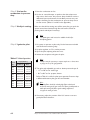
Table 4.1 Pilot Capacities
Input (Btu/hr.)
Burner
Size Main Burner
Pilot
6V
8V
10V
12V
6,000,000
10,500,000
17,000,000
23,000,000
60,000
105,000
170,000
230,000
14V
16V
18V
22V
32,000,000
42,000,000
55,000,000
78,000,000
320,000
420,000
550,000
780,000
24V
28V
32V
36V
90,000,000
125,000,000
160,000,000
210,000,000
900,000
1,250,000
1,600,000
2,1000,000
Note:
Initially it may be necessary to repeat step 4 two or three times
to purge air out of the gas pipework.
5. Trim pilot with adjustable gas cock to obtain pressure drops of:
• 1.5" to 2.0"w.c. for natural gas
• 0.6" to 0.9"w.c. for propane, butane
Refer to Table 4.1 at left for pilot input capacities. Pressure drop
is differential between pilot gun inlet and chamber.
Note:
The pilot flame should be a bushy, blue flame which curls
around the main gas/oil gun nozzle. This flame should provide a
stable pilot with good flame signal readings sufficient to
energize the main gas valve.
6. If necessary, adjust the position of the U.V. scanner to ensure
good pilot flame detection.
4-2
Eclipse Vortometric Burner v2.00, Installation Guide 248, 4/10/07
Step 5: Ignite the burner
Note:
This procedure assumes that automatic flame safety is installed
and is serviceable.
For Gas Burners
1. Make sure the supply air fan is running.
2. Adjust the main gas regulator to supply the minimum pressure
required; see the Appendix for gas pressure drop information.
3. Verify that the main gas control valve is at its minimum open
position.
4. Light the pilot.
5. Open all manual fuel shut-off valves.
6. Initiate the ignition sequence through the flame safety.
7. Check that the pilot and main burner flames have ignited.
8. The gas flame should be a pale blue color set inside the
refractory combustion block.
Note:
Combination gas/oil burners may be operated on gas with the
oil gun in place provided that the atomizing medium is left on
at a minimum pressure of 5 to 10 psig. When shutting down,
leave the atomizing medium on until the block and combustion
chamber are cool.
Combination gas/oil burners may also be operated with the oil
gun and oil gun gland removed; see Figure 3.2 on page 3-5 for
gland “A” identification and location.When doing so, a blanking
plate must be substituted for gland “A” at the rear of the gas gun.
Eclipse Vortometric Burner v2.00, Installation Guide 248, 4/10/07
4-3
For Oil Burners
1. Make sure the supply air fan is running.
2. Adjust the main oil regulator to supply the minimum pressure
required; see the Appendix for oil nozzle pressure drop information.
3. Turn on the atomizing medium and adjust atomizing pressure
to approximately 20 to 30 psig.
Note:
If using heavy oil as the fuel with either steam or preheated air
for atomization, then warm up the oil feed pipe and fuel oil
nozzle by running the atomizing medium through the burner
bypass valve. Leave this bypass valve open for 5 to 10 minutes.
4. If steam is being used for atomization, allow plenty of time to
drain the system of accumulated condensate and ensure steam
traps are working.
5. Verify that the main oil control valve is at its minimum open
position.
6. Light the pilot.
7. Open all manual fuel shut-off valves.
8. Initiate the ignition sequence through the flame safety.
9. Check that the pilot and main burner flames have ignited.
10. The oil flame should be a bright yellow color set inside the
refractory combustion block.
Step 6: Adjust low fire
Note:
The first time that the burner is started, allow the refractory
combustion block to warm up slowly to reduce thermal shock.
Refer to “Installing and Curing Refractory Block” in Chapter 3
for details.
If necessary, adjust the main control valve’s minimum open position
to obtain the desired low fire setting.
Step 7: Adjust high fire
For Gas Burners
1. Drive the main gas control valve to high fire.
2. Measure the gas pressure drop at high fire and compare to the
appropriate chart in the Appendix. If the maximum input is not
4-4
Eclipse Vortometric Burner v2.00, Installation Guide 248, 4/10/07
achieved or is too high while the main gas control valve is fully open,
two adjustments can be made:
a. the main gas control valve can be adjusted open or closed, or
b. the main gas pressure regulator can be adjusted higher or lower.
3. The main gas flame should have a slightly blue periphery and a
somewhat yellowish center at high fire; refer to Table 4.2 below
for flame length estimates.
For Oil Burners
1. Drive the main oil control valve to high fire.
2. Measure the oil pressure drop at high fire and compare to the
appropriate chart in the Appendix. If the maximum input is not
achieved or is too high while the main oil control valve is fully open,
two adjustments can be made:
a. the main oil control valve can be adjusted open or closed, or
b. the main oil pressure regulator can be adjusted higher or lower.
3. Note the atomizing air pressure. If modulating control is used,
the atomizing pressure should be approximately 20 psig above
the oil pressure without exceeding 50/55 psig.; refer to
“Modulating Control” on page 3-10 for further details.
4. The high fire oil flame should be bright yellow; refer to Table 4.2
below for flame length estimates.
Step 8: Verify settings
1. Once the high and low fire conditions have been set, cycle the burner
from high to low fire several times to check repeatability of settings.
2. Shut down the burner and relight to ensure automated pilot and
main flame ignition operates correctly.
3. Check all safety interlocks and limits to ensure proper operation.
Table 4.2 Flame Sizes
Flame Length (ft.)
Burner
MI or HI*
Burner
Input
Flame
MI*
HI*
Size (MMBtu/hr.) Dia. (in.) Burner Burner
6V
6.0
30
6.0
5.0
8V
10.5
32
7.0
6.0
10V
17.0
36
8.0
7.0
12V
23.0
40
9.0
8.0
14V
16V
18V
22V
32.0
42.0
55.0
78.0
46
52
58
64
10.5
12.0
13.0
15.0
9.0
10.0
11.0
13.0
24V
28V
32V
36V
90.0
125.0
160.0
210.0
68
78
86
96
16.0
18.0
20.0
24.0
14.0
16.0
17.0
20.0
Note:
Flame lengths are measured
from the open end of the
combustor.
Flame lengths are estimates
based on general operating
conditions and are useful for
design purposes. Actual flame
lengths will depend on
chamber size and presence of
secondary air.
* MI means Medium Intensity and HI means High Intensity.
Eclipse Vortometric Burner v2.00, Installation Guide 248, 4/10/07
4-5
START PROCEDURE
1. Start the air supply fan.
2. Open all the gas or oil cocks.
3. Start the automatic ignition sequence.
Danger:
If a burner does not light, and the system does not
shut down automatically, then you must close the
main gas cock on gas burner systems. An uncontrolled
flow of gas can cause fires and explosions.
Do not touch the ignition plug or the ignition wire
when the ignition is on. You will get a shock.
4. Make sure that you can see the flame in the burner system.
If the burner system does not light and
– the system does not shut down automatically:
then close the main gas or oil cock manually. DO NOT
operate the system. Go to “Checklist after Installation” on
page 3-8 and verify the steps. After that, repeat the start
procedure.
– the system shut downs automatically:
then see the “Trouble-shooting” Tables in the next chapter.
4-6
Eclipse Vortometric Burner v2.00, Installation Guide 248, 4/10/07
STOP PROCEDURE
For Gas Burners
1. Drive combustion air and gas valves to low fire position.
2. Shut off main gas supply valves and pilot.
3. Leave combustion air at low fire until combustion chamber and
block are cooled; once cooled, shut off combustion air fan.
4. Shut off all manual valves as required.
For Oil Burners
1. Drive combustion air and fuel valves to low fire position; shut
down the oil supply.
2. Turn on the pilot.
3. Purge the oil nozzle with the atomizing medium through the
bypass connection valves.
4. When the oil nozzle is clear of oil, then turn off the pilot.
5. Leave combustion air and atomizing medium on until the
combustion chamber and block are cooled; once cooled, shut off
the combustion air and atomizing medium supplies.
6. Shut off all manual valves as required.
Eclipse Vortometric Burner v2.00, Installation Guide 248, 4/10/07
4-7
Eclipse Vortometric Burner v2.00, Installation Guide 248, 4/10/07
Maintenance &
Trouble-shooting
5
INTRODUCTION
This section is divided into two parts:
• The first part describes the maintenance procedures.
• The second part helps you to identify problems that may occur,
and gives advice on how to solve these problems.
MAINTENANCE
Preventative maintenance is the key to a reliable, safe and efficient
system. The following are sugested guidelines for periodic
maintenance. Burners in severe environments or operational
conditions should be checked more frequently.
SCHEDULES
Note:
The monthly and yearly lists are an average interval. If your
environment is dirty, then the intervals may be shorter. Check
with local authorities having jurisdiction on their recommended
maintenance schedules.
Caution:
Turn off power to burner and controls before proceeding with
burner inspection.
Monthly Checklist
1. Inspect flame-sensing devices for good condition and cleanliness.
2. Test all alarms for proper signals.
3. Check ignition spark electrode operatin and check proper gap.
4. Check all valve motors and control valves for free, smooth
action and adjustment.
5. Test interlock sequence of all safety equipment and manually
make each interlock fail, noting that related equipment closes
or stops as specified by the manufacturer. Test flame safeguard
by manually shutting off gas to burner.
6. Test all manual fuel valves for operation.
7. Check filters on main air fan for cleanliness.
8. Check gas filter or strainers.
Eclipse Vortometric Burner v2.00, Installation Guide 248, 4/10/07
5-1
Yearly Checklist
1. Test (leak test) safety shut-off valves for tightness of closure.
2. Test pressure switch settings by checking switch movements
against pressure settings.
3. Visually check ignition cable and connectors.
4. Check the refractory combustion block to ensure that it is not
badly cracked or spalled. Minor hairline cracks are of no
consequence and should be considered normal. Examine the
refractory around the throat cone, since this area is where
breakage can easily occur. If repairs are needed to this area,
ensure that any new refractory is installed to the original
contours and surface texture.
5. Remove the pilot assembly and examine the ceramic insulators
on the spark rods. Clean the spark rod end with a fine emery
cloth. Adjust the spark gap to no more than 1/8".
6. Remove the gas gun assembly and clean the gas orifices. Use
compressed air to blow all scale or dust out of the ports.
7. Remove the oil gun assembly, and clean the oil injection orifices
and atomizing air nozzles according to the instructions that
follow in this chapter.
MAINTENANCE
Fuel Oil Tip Cleaning
PROCEDURES
Vortometric burner sizes 6V through 12V use an oil nozzle held by
a retaining ring. With these sizes, the nose cone assembly must be
unscrewed from the body to remove or replace the entire tip.
Vortometric burner sizes 14V and larger use an oil nozzle which is
made in two pieces, which allows the outer end of the tip to be removed from the nozzle body. Therefore, the tip head containing the
oil orifices can be removed for cleaning without dismantling the entire atomizer.
Note:
On a burner with CLOCKWISE air rotation, the tip head has LEFT
HAND threading. On a burner with COUNTERCLOCKWISE air
rotation, the tip head has RIGHT HAND threading.
5-2
Eclipse Vortometric Burner v2.00, Installation Guide 248, 4/10/07
When inspecting and cleaning the fuel oil tips, please observe
the following:
• Vortometric oil nozzles are manufactured of stainless steel, with
all surfaces manufactured to close tolerances and highly polished.
Therefore, avoid marring the nozzle’s machined surfaces in any
way when the atomizer is dismantled.
• Never use abrasive cleanser or emery cloth on the internal surfaces of the nose cone. However, a wire brush may be used on the
outside surfaces of the nose cone where carbon has accumulated.
Table 5.1 Fuel Oil Tip Data
Burner No. of
Size
Holes
Hole
Drill
Dia. (in.) Size
6V
8V
10V
12V
4
6
6
9
.0400
.0400
.0469
.0430
60
60
3/64
57
14V
16V
18V
22V
10
10
12
12
.0469
.0550
.0595
.0670
3/64
54
53
51
24V
28V
32V
36V
12
12
12
16
.0730
.0860
.0980
.0980
49
44
40
40
If the oil tip holes become blocked, you cannot clear the blockage by
forcing the atomizing medium through them. Instead, the tip must be
removed and cleaned out. Care should be taken when dismantling
and cleaning the oil tip to avoid burring or other damage. After removing the tip, the recommended cleaning procedure is as follows:
1. Soak the tip in a solvent such as Varsol, especially if the atomizer
has been used with heavy oil.
2. Blow out the tip with compressed air in the reverse direction to
the oil flow.
3. Wash the tip again in solvent.
4. Select the correct drill size needed from Table 5.1. Use a new bit
to avoid potential marring. Insert the drill bit by hand into each
hole in the oil tip to clear any hard carbon or other residue.
Caution:
Forcing an oversized drill bit into the oil tip holes will ruin the tip.
5. Repeat Step 2.
6. Repeat Step 3.
7. Before reassembling the oil tip in the atomizer assembly, clean
out the oil feed pipe with either compressed air or solvent as
necessary.
Eclipse Vortometric Burner v2.00, Installation Guide 248, 4/10/07
5-3
Dismantling of Atomizer
Note:
Refer to Figure 5.1 for oil nozzle component identification and
location.
1. Remove the complete oil gun from the burner by removing the
bolts on the rear flange of the gun assembly.
2. Place the oil gun in a pipe vise.
3. Loosen the bolts on the packing gland at the rear (outer) end of
the oil gun.
4. Using a spanner wrench, loosen the nose cone assembly, which
has a standard right hand thread.
5. After freeing the nose cone assembly from the threaded portion
of the body, pull the nose cone foward enough to expose the
base and tip retaining ring.
6. Using two adjustable wrenches, loosen the retaining ring from
the base, then slide the retaining ring back on the fuel pipe to
expose the wrench flats on the end of the oil tip.
7. Using an adjustable wrench on the flats of the oil tip, grasp the
nose cone assembly and rotate it while pulling it foward. This
action separates the nose cone inlet ring and base assembly from
the tip. Be careful not to lose or damage the spacer washers.
8. Remove the oil tip by using a pipe wrench on the fuel oil feed
pipe and an adjustable wrench on the oil tip flats.
9. Refer to the previous section, “Fuel Oil Tip”, for the proper oil
tip cleaning procedure.
10. If you need to dismantle the atomizer further, then remove the cap
screws and carefully separate the nose cone, inlet ring and base.
11. Wash all parts with a solvent such as Varsol. Wipe all parts
clean of any foreign material.
Note:
Due to the tight fit between the oil tip and base, no foreign
material can be left on the tip’s outside surface OR the base’s
inside surfaces. Foreign material such as grit can cause scoring
of these surfaces and possible binding of the two surfaces. If
necessary, a very fine emery cloth may be used to restore them.
5-4
Eclipse Vortometric Burner v2.00, Installation Guide 248, 4/10/07
12. Referring to Table 5.2, select the correct drill size. Use this drill
bit to check the hole diameters of the venturi inlets in the
tangential inlet ring. If the holes are worn beyond the
corresponding maximum throat diameter number shown in
Table 5.2, then replacing the venturi insert should be
considered.
13. Examine the flat faces of the base and nose cone, which form
the front and rear of the vortex chamber, respectively. Although
slight “dimpling” of the surfaces adjacent to the inlet holes is
normal, pitting and scoring is not. Clean these surfaces with
solvent if they appear oily or sooty.
14. Clean any accumulated carbon from the internal bore of the
nose cone, but do not scratch or mar these surfaces.
Figure 5.1 Atomizer Assembly Components
6
1
1 Atomizing Medium Inlet
2 Oil Inlet
3 Oil Nozzle Retaining Ring
8
2
9
3
4
7
5
4
5
6
7
8
9
Body
Spacers
Base
Inlet Ring
Nose Cone
Oil Nozzle
Table 5.2 Atomizing Inlet Ring Data
Burner
Size
6V
8V
10V
12V
Orig.
Max.
Max.
Insert
Orig.
Worn
Worn
No. of Throat
Drill
Throat
Drill
Inserts Dia. (in.) Size Dia. (in.) Size
6
.0760
48
.0820
45
6
.0995
39
.1093
7/64
6
.1250
1/8
.1360
29
6
.1440
27
.1570
22
14V
16V
18V
22V
6
6
6
10
.1695
.1935
.2130
.1960
18
10
3
9
.1875
.2130
.2340
.2130
3/16
3
A
3
24V
28V
32V
36V
10
10
10
10
.2090
.2420
.2720
.3020
4
C
I
N
.2280
.2656
.2968
.3320
1
17/64
19/64
Q
Eclipse Vortometric Burner v2.00, Installation Guide 248, 4/10/07
5-5
Assembly of Atomizer
1. With all of the parts clean of foreign material, put a smear of
anti-seize compound or similar lubricant on all mating surfaces
and on all threads.
2. Slide the retainer ring onto the fuel pipe.
3. Screw the fuel pipe into the oil tip and tighten securely.
4. Assemble the base and inlet ring onto the nose cone using the
provided cap screws. Tighten all cap screws securely and evenly.
The tangential inlet ring can provide either clockwise or
counterclockwise rotation to the steam. However, the steam’s
rotation direction (as viewed through the rear of the atomizer)
MUST match the rotation direction of the air flow through the
burner assembly’s vanes.
5. Install a new oil tip spacer (standard size of 0.030") on the oil tip,
and insert the tip into the atomizer base. Step 7 details what size
of spacers should be used to properly locate the oil tip.
6. Tighten the retainer ring securely, using the wrench flats on the
ring and on the base.
7. Check the relationship of the oil holes to the nose cone by
inserting the specified drill from Table 5.1 into the oil holes as
shown at left. The drill’s sides should JUST TOUCH the nose
cone’s lip. If you have trouble inserting the drill into the oil holes,
there are two probable causes:
a. if the drill cannot be inserted easily, then the oil tip is too far
back in the nose cone; a thinner spacer is needed so the oil
tip can come further forward, or
b. if there is an obvious space between the drill and the nose
cone lip, then the oil tip is too far forward; more spacers are
needed to move the tip further back.
Each atomizer assembly is provided with three spacers of nominal
thickness from 0.010" to 0.030"; the 0.030" spacer is the one
generally used on the assembly. Depending on your situation, any
one or combination of these spacers may be necessary to
correctly locate the oil jets.
8. Once the oil tip is correctly located, loosen the packing gland
at the outer end of the atomizing steam pipe. Insert the entire
atomizer assembly, including the fuel pipe, into the body and
atomizing steam pipe.
9. Screw the nose cone assembly into the body threads, being
careful not to get it cross-threaded. Tighten the assembly
securely with a spanner wrench.
5-6
Eclipse Vortometric Burner v2.00, Installation Guide 248, 4/10/07
10. Tighten the packing gland at the outer end of the atomizing
steam pipe. A final check on the location of the oil holes in
relation to the nose cone lip can be done as follows:
a. Connect the oil feed line to a water supply line and spray
water out of the nozzle at 5 PSIG.
b. If properly located, then the water streams emerging out of
the oil holes should be separate, distinct and uniform; the
water streams should also clear the inside lip of the nose
cone or just barely touch the lip’s edge.
11. Reinstall the oil gun into the burner and connect all hoses securely.
Eclipse Vortometric Burner v2.00, Installation Guide 248, 4/10/07
5-7
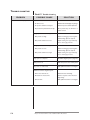
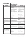
TROUBLE-SHOOTING
Table 5.1 Trouble-shooting
PROBLEM
Cannot initiate start-up sequence.
POSSIBLE CAUSE
SOLUTION
Air pressure switch has not made contact:
• Air flow too low.
Check air flow and investigate any changes.
• Air pressure switch incorrectly set.
Check air pressure switch adjustment.
• Air pressure drop measured incorrectly.
Move pressure taps on chamber to a
better location.
High gas pressure switch has tripped:
• Gas pressure too high.
Check incoming gas pressure against
initial settings; adjust as required.
• Gas pressure switch set too low.
Adjust setting to be approximately
4" w.c. above gas pressure.
Low gas pressure switch has tripped:
• Gas pressure too low.
Check incoming gas pressure against
initial settings; adjust as required.
• Gas pressure switch set too high.
Adjust setting to be approximately
4" w.c. below gas pressure.
Purge cycle not completed.
Check flame safeguard system or purge timer.
Main power is off.
Make sure power is on to control system.
No power to control unit.
Call qualified electrician to investigate.
Malfunction of flame safeguard system:
5-8
• Flame sensor shorted out.
Check UV sensor and wiring.
• Electrical noise in sensor line.
Shield or separate sensor lines from
high voltage.
• Unit is broken.
Call qualified electrician to investigate.
Eclipse Vortometric Burner v2.00, Installation Guide 248, 4/10/07
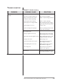
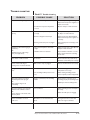
TROUBLE-SHOOTING
Table 5.1 Trouble-shooting
PROBLEM
Start-up sequence runs but pilot does
not light.
POSSIBLE CAUSE
SOLUTION
No spark:
• No power to ignition transformer.
Have electrician investigate.
• Open circuit between the ignition
transformer and the spark plug.
Repair or replace wiring to spark plug.
• Spark plug has carbon build-up.
Clean or replace spark plug.
• Spark plug not correctly grounded.
Clean spark plug threads. Do not apply
grease or pipe compound to pipe threads.
• Spark plug gap is incorrect.
Set gap to 1/8".
• Spark is shorting inside pilot pipe
Remove spark plug and clean inside
of pipe and star insulators.
Not enough pilot gas:
• Pilot gas regulator set too low.
Check incoming gas pressure against
initial settings; increase as necessary.
• Gas pressure into pilot regulator too low.
Check outgoing gas pressure of main
regulator; increase as necessary.
• Pilot gas cock closed.
Open pilot gas cock.
• Pilot solenoid valve does not open.
Have qualified electrician check
power supply to solenoid.
• Pilot adjusting valve set too low.
Adjust gas flows to give pressures/
flows indicated on page 4-2.
• Air in the gas line.
Repeat start-up several times to
purge air out of gas lines.
Too much gas.
Trim pilot gas adjusting valve to give
pressures/flows indicated on page 4-2.
Eclipse Vortometric Burner v2.00, Installation Guide 248, 4/10/07
5-9
TROUBLE-SHOOTING
Table 5.1 Trouble-shooting
PROBLEM
Start-up sequence runs, pilot lights but
main burner does not light.
POSSIBLE CAUSE
No UV signal.
SOLUTION
Check wiring and control logic.
Not enough main fuel:
• Main fuel regulator set too low.
Check outgoing fuel pressure of main
regulator; increase as necessary.
• Fuel pressure into main regulator too low.
Check incoming fuel pressure against
initial settings; increase as necessary.
• Main fuel cock closed.
Open all fuel cocks.
• Main safety shut-off valve does not open.
Have qualified electrician check
power supply and safety circuitry.
• Main fuel control valve set too low.
Adjust fuel flows to give pressures
indicated in Appendix.
• Air in the gas line.
Repeat start-up several times to
purge air out of gas lines.
• No fuel oil to nozzle.
Repeat start-up several times to fill
oil lines and nozzle. Reduce piping
length if necessary.
Too much gas.
Trim control valve to give pressure
indicated in Appendix.
Pilot ignites but flame safeguard shuts
down burner.
No UV signal.
Burner kicks out shortly after start-up.
Low main fuel pressure switch is set too
high.
Check wiring and control logic.
Adjust position of UV sensor with
swivel mount.
Check and reset low pressure switch
setting.
The low fire flame is weak and
unstable.
• Not enough fuel.
Check start-up settings and adjust to
increase fuel flow.
• Too much air.
Check combustion air pressure drops/
flow across the burner and adjust.
• Not enough fuel pressure into main fuel
regulator.
Adjust pressure regulator so pressure
is provided at burner as specified in
this manual.
• Fuel pressure drops as input is increased.
Check for clogging of valves and
regulators in fuel line.
• Main fuel control valve is not functioning.
Check actuator and linkage.
Main flame is uneven and not
centered in the refractory block.
• Incorrectly positioned gas/oil gun.
Ensure gas/oil gun is centered within
the throat cone.
Main flame pulsates or is unstable.
• Unstable air flow.
Check blower/air system for
pressure pulsations.
• Unstable fuel flow.
Check pressure regulator and
control valve for pulsations.
• Pilot gun inserted too far.
Pull back pilot gun.
Burner does not go to high fire.
5-10
Eclipse Vortometric Burner v2.00, Installation Guide 248, 4/10/07
TROUBLE-SHOOTING
Table 5.1 Trouble-shooting
PROBLEM
POSSIBLE CAUSE
SOLUTION
• Fuel pressure too high at burner inlet.
Check fuel pressure against design.
Adjust main fuel pressure regulator, or
adjust control valve.
• Combustion air pressure drop/flow is
too low.
Open air damper on main air blower.
• Combustion air pressure drop/flow is
too high.
Check pressure drop or flow. Check
air damper on main air blower.
• Burner is firing below rated input.
Check fuel pressure differential/flow.
Adjust main fuel pressure regulator as
necessary.
• Burner gas holes/oil ports are plugged.
Inspect holes/ports for blockage; clean
as needed.
Main flame is yellow and long (in gas
applications)
OR
Main flame appears a dull orange
color (in oil applications).
• Air pressure drop/flow is lower than
design.
Check pressure drop or flow. Open air
damper on main air blower.
• Windbox air flow is restricted.
Inspect windbox and blower to ensure
that no foreign material is restricting
the air flow.
Main oil flame is white and hard.
Too much air.
Check combustion air pressure drop/
flow. Close control damper as necessary.
Uneven oil flame with stingers
shooting out to one side of the block.
Orifices in the oil tip are plugged.
Remove oil nozzle and clean as necessary.
Orange or red “sparklers” in the oil
flame.
• The oil is too cold.
Check oil heating system; increase
temperature as necessary.
• The atomizing medium pressure is too
low.
Check existing atomizing pressure
versus required (see table in Appendix).
Flame temporarily becomes black
and smokey, then clears up again
OR
Flame sputters and goes out
momentarily.
Moisture (condensate) in the atomizing
medium.
Ensure that the condensate trap is
operating properly for atomizing steam.
Fiery ring of burning oil on the inside
diameter of the combustor surface
OR
Carbon deposits on the inside of the
refractory block.
Poor atomization.
Carbon accumulation on the oil
nozzle cone.
Oil nozzle is too far forward into the
throat.
Main flame is too large at high fire.
Main flame does not achieve
capacity.
Install dryers in the atomizing air line.
Check atomizing pressure and adjust as
necessary.
Check oil nozzle ports for clogging.
Move gun back 1/4" at a time until
carbon no longer accumulates.
Eclipse Vortometric Burner v2.00, Installation Guide 248, 4/10/07
5-11
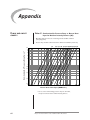
Appendix
FLOW AND INPUT
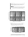
Table A.1 Combustion Air Pressure Drop vs. Burner Heat
Input for Medium Intensity Burners (MI)
CHARTS
• Operation with 15% excess air on natural gas under standard conditions
(14.7 psia @ 70°F).
• Pressure drop should be taken between the chamber and windbox pressure tap.
8V
7.5
6V
6
5
Combustion Air Pressure Drop ("w.c.)*
10V 12V 14V 16V 18V 22V24V 28V 32V 36V
4
3
2
1
0.8
0.6
0.4
0.2
0.1
0.6 0.8 1
2
4
6
8 10
20
40
60 80 100
Burner Gross Heat Input (MMBtu/hr.)
* 7.5"w.c. is the nominal design pressure drop for all models,
except for model 6V of the medium intensity burners.
A-1
Eclipse Vortometric Burner v2.00, Installation Guide 248, 4/10/07
200
300
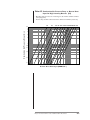
Table A.2 Combustion Air Pressure Drop vs. Burner Heat
Input for High Intensity Burners (HI)
• Operation with 15% excess air on natural gas or #2 oil under standard conditions
(14.7 psia @ 70°F).
• Pressure drop should be taken between the chamber and windbox pressure tap.
6V
7.5
8V
10V 12V 14V 16V 18V 22V 24V 28V 32V 36V
Combustion Air Pressure Drop ("w.c.)
6
5
4
3
2
1
0.8
0.6
0.4
0.2
0.1
0.6 0.8 1
2
4
6
8 10
20
40
60 80 100
200
300
Burner Gross Heat Input (MMBtu/hr.)
Eclipse Vortometric Burner v2.00, Installation Guide 248, 4/10/07
A-2
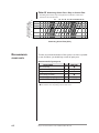
Table A.3 Gas Gun Press. Drop vs. Burner Heat Input
• Pressure drops for natural gas, 1,000 Btu/SCF gross, 0.6 specific gravity.
• Pressure drop should be taken as differential between the chamber and gas gun
pressure tap.
Gas Gun Pressure Drop ("w.c.)*
Note:
Fuel pressure drop curves should be used as a guide for setting up
burner. It is recommended to use a direct fuel flow measurement
(orifice plate or flow meter) for calculating actual fuel flows.
6V
24
20
8V
10V 12V 14V 16V
10
8
6
4
2
1
1
2
4
6
8 10
20
40
60
Burner Gross Heat Input (MMBtu/hr.)
or Natural Gas Flow (1000’s SCFH)
18V 22V 24V 28V 32V 36V
45
Gas Gun Pressure Drop ("w.c.)*
30
20
10
8
6
4
2
1
1
2
4
6
8 10
20
40
60
100
Burner Gross Heat Input (MMBtu/hr.)
or Natural Gas Flow (1000’s SCFH)
* Nominal pressure drop at maximum capacity is 24"w.c. for
6V through 16V models, and 45" w.c. for all other models.
A-3
Eclipse Vortometric Burner v2.00, Installation Guide 248, 4/10/07
200
300
Table A.4 Oil Nozzle Press. Drop vs. Burner Heat Input
• Pressure drops for #2 Oil with 137,000 Btu/lb. gross heating value.
Note:
Fuel pressure drop curves should be used as a guide for setting up
burner. It is recommended to use a direct fuel flow measurement
(orifice plate or flow meter) for calculating actual fuel flows.
10V
40
12V 14V 16V 18V 22V 24V 28V 32V 36V
8V
6V
20
10
8
6
4
2
1
2
4
6
8 10
20
40
60
80 100
200
300
Burner Gross Heat Input (MMBtu/hr.)
Table A.5 Atomizing Air Pressure Drop vs. Air Flow
• When air is used for atomization of heavy oil, it should be preheated to
approximately the same temperature as the oil.
Atomizing Air
Pressure Drop (psig)
Oil Nozzle Pressure Drop (psig)
60
60
50
8V
10V 12V 14V 16V 18V 22V 24V 28V 32V 36V
40
60
6V
40
30
20
15
10
10
20
80 100
200
400
600
1,000
Atomizing Air Flow (SCFM)
Eclipse Vortometric Burner v2.00, Installation Guide 248, 4/10///
A-4
Table A.6 Atomizing Steam Press. Drop vs. Steam Flow
Atomizing Steam
Pressure Drop (psig)
• Atomizing steam must be dry and superheated a minimum of 20°F above
saturated at the atomizer inlet.
8V
60
50
10V 12V 14V 16V 18V 22V 24V 28V 32V 36V
6V
40
30
20
15
10
10
20
40
60
80 100
200
400
600
1,000
2,000
4,000
Atomizing Steam Flow (lb/hr)
RECOMMENDED
SPARE PARTS
To make sure that the downtime of the system is as short as possible
in case of a failure, you should keep a stock of spare parts.
Recommended spare parts
PART NAME
Pilot assembly
Spark rod assembly
Oil gun assembly
U.V. scanner (if used)
1-1/4" N.P.T. peepsight glass
1-1/4" N.P.T. peepsight gasket
QTY.
PART NO.
1
1
1
2
2
2
1
1
1
2
13046
13047
1 Part number varies depending on burner size used.
2 Part number varies depending on U.V. scanner used.
A-5
Eclipse Vortometric Burner v2.00, Installation Guide 248, 6/00
CONVERSION
FACTORS
Metric to English.
FROM
TO
MULTIPLY BY
cubic meter (m3)
cubic foot (ft3)
35.31
cubic meter/hour (m /h)
degrees Celsius (°C)
cubic foot/hour (cfh)
degrees Fahrenheit (°F)
35.31
(°C x 1.8) + 32
kilogram (kg)
kilowatt (kW)
pound (lb)
Btu/hr
2.205
3414
meter (m)
millibar (mbar)
foot (ft)
inches water column ("wc)
3.28
0.401
millibar (mbar)
millimeter (mm)
pounds/sq in (psi)
inch (in)
14.5 x 10⁻³
3.94 x 10⁻²
FROM
TO
MULTIPLY BY
kiloPascals (kPa)
millibar (mbar)
10
meter (m)
millibar (mbar)
millimeter (mm)
kiloPascals (kPa)
1000
0.1
millimeter (mm)
meter (m)
0.001
FROM
TO
MULTIPLY BY
Btu/hr
cubic foot (ft3)
kilowatt (kW)
cubic meter (m3)
0.293 x 10⁻³
2.832 x 10⁻²
cubic foot/hour (cfh)
degrees Fahrenheit (°F)
cubic meter/hour (m3/h)
degrees Celsius (°C)
2.832 x 10⁻²
(°F – 32) ÷ 1.8
foot (ft)
inches (in)
meter (m)
millimeter (mm)
0.3048
25.4
inches water column ("wc)
pound (lb)
millibar (mbar)
kilogram (kg)
2.49
0.454
pounds/sq in (psi)
millibar (mbar)
68.95
3
Metric to Metric.
English to Metric.
Eclipse Vortometric Burner v2.00, Installation Guide 248, 6/00
A-6
SYSTEM SUMMARY
GENERAL SYSTEM
PARAMETERS
Customer:
Customer P.O.:
Write down the settings for the burner system in the table that follows:
BURNER SETTINGS
HIGH FIRE
LOW FIRE
Main gas pressure:
Air pressure from the blower:
Customer signature:
Air pressure drop across the burner:
Date:
Gas pressure drop across the burner:
Furnace type:
Furnace temperature:
Number of burners:
High fire input per burner:
Orifice sizes:
Operating voltage & frequency:
Main oil pressure:
Oil pressure across the burner:
Atomizing pressure:
Atomizing pressure drop across the burner:
Flame signal strength:
Flame length:
Altitude:
A-7
Eclipse Vortometric Burner v2.00, Installation Guide 248, 6/00
Offered By:
Power Equipment Company
2011 Williamsburg Road
Richmond, VA 23231
Phone: 804-236-3800 Fax: 804-236-3882
www.peconet.com