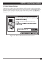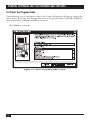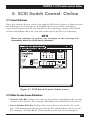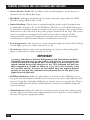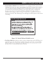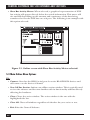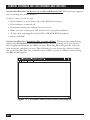
1
IC501A
SC120A-R2
SC121A
SC122A-R2
AUGUST 2002
SC123A
SW485A
SW487A-R2
SW488A
SW489A
Control Software for
SCSI Fiber Optic Extender,
SCSI Matrix Switches, and
6 x 4 Electronic SCSI Switch
CUSTOMER
SUPPORT
INFORMATION
Order toll-free in the U.S.: Call 877-877-BBOX (outside U.S. call 724-746-5500)
FREE technical support 24 hours a day, 7 days a week: Call 724-746-5500 or fax 724-746-0746
Mailing address: Black Box Corporation, 1000 Park Drive, Lawrence, PA 15055-1018
Web site: www.blackbox.com • E-mail: [email protected]
LICENSE AGREEMENT
LICENSE AGREEMENT
This manual is shipped with Control Software for your SCSI Switch or Extender.
Do not install or use the Software until you have read this License Agreement. By
installing or using the Software (or authorizing any person to do so), you accept
this License Agreement. If you do not accept this License Agreement, you must
return the Software unused.
1. Software. The computer programs and documentation which accompany this
Agreement are referred to collectively as the “Software.”
2. Product. The “Product” includes the Software, the medium on which it is
shipped from the factory, and any accompanying accessories meant to be
actively used with it. The manufacturer and its authorized agents own the
copyrights and intellectual property on this Product.
3. Licensee. “Licensee” is the person or entity who purchased this Product
(including the License) or for whom it was purchased.
4. License. The purchase of the Product includes the purchase of the following
license. The manufacturer and its authorized agents grant to Licensee, and
Licensee purchases, a nonexclusive, nontransferable license (the “License” )
to use the software included in this package on a single active server
computer. Licensee may transfer the Software to other computers and use the
Software on other computers, provided that the Software is not at any one
time resident on or used by more than a single active server computer. Rights
not expressly granted are reserved by the manufacturer and its authorized
agents.
5. Copies. Licensee may make copies of the Software provided that any such new
copy: (i) is created as an essential step in the utilization of the Software on the
licensed computers and is used in no other manner, or (ii) is only for archival
purposes to back up the licensed computers. All trademark and copyright
notices must be faithfully reproduced and included on such copies. Licensee
may not make any other copies of the Software.
6. Protection of Software. Licensee may not: (i) disassemble, decompose, or
otherwise reverse engineer the Software, or (ii) create derivative works based
upon the Software, or (iii) rent, lease, sublicense, distribute transfer, modify
or timeshare the Software.
7. Ownership. Ownership of, and title to, the Software and all copies thereof
(including copies provided with this Agreement and copies under
Paragraph 5) shall be held by the manufacturer and its authorized agents.
1
CONTROL SOFTWARE FOR SCSI EXTENDER AND SWITCHES
8. Disclaimer of Warranties and Limitation on Liability. The manufacturer and
its authorized agents disclaim and exclude all implied warranties of
noninfringement, merchantability, or fitness for a particular purpose. The
manufacturer and its authorized agents do not warrant that this Product will
satisfy Licensee’s requirements or that the operation thereof will be
uninterrupted.
The aggregate liability of the manufacturer and its authorized agents
arising from or relating to this agreement or the Product (regardless of the
form of action or claim, including but not limited to contract, warranty, tort,
strict liability, malpractice, or fraud) is limited to the purchase price of this
Product. Neither the manufacturer nor any of its authorized agents shall be
liable for any special, incidental, consequential, indirect, or punitive damages,
even if the manufacturer or any of its authorized agents has been advised of
the possibility of such damages.
In no event shall the manufacturer or any of its authorized agents be
liable for any lost profits or for direct, indirect, special, incidental, or
consequential damages, whether based on contract, tort, or any other legal
theory.
NOTE
Some states may not allow certain disclaimers or limitations, so they
may not be applicable to Licensee.
9. Governing Law. This Agreement shall be governed by the laws of the State of
Oregon and the United States of America.
10. Entire Agreement. This Agreement sets forth the entire understanding and
agreement between the parties and may be amended only in a writing signed
by both parties.
11. Termination. The License shall automatically terminate if Licensee breaches
this Agreement. Upon termination of the License, Licensee shall deliver to
Black Box the original and all other copies of the Software.
12. U.S. Government Restricted Rights. The Software is provided with
RESTRICTED RIGHTS. Use, duplication, or disclosure by the manufacturer
or any of its authorized agents is subject to restrictions as set forth in
subparagraph (c) (1)(ii) of the Rights in Technical Data and Computer
Software Clause at DFARS 252.227-7012 or subparagraphs (c)(1) and (2) of
the Commercial Computer Software Restricted Rights at 48 CFR 52.227019, as
applicable.
2
LEGAL INFORMATION, TRADEMARKS
NOTICES AND DISCLAIMERS
This manual is copyrighted. All rights are reserved. No part of this manual may be
reproduced, transmitted, copied, or translated in any form or by any means,
electronic or mechanical, including photocopying and recording, for any purpose
without the express written permission of the manufacturer or its authorized
agents. The software described in this document is furnished under a license
agreement or nondisclosure agreement. The hardware and software may be used
or copied only in accordance with the terms of the agreement. It is against the law
to copy the software on any medium except as specifically allowed in the license or
nondisclosure agreement.
The manufacturer and its authorized agents reserve the right to revise this
publication from time to time without obligation on their part to notify any person
or organization of such revision. The manufacturer and its authorized agents have
prepared this manual for use by customers as a guide for proper installation,
operation, and maintenance of their software. The drawings, specifications, and
information contained within this document are the property of the manufacturer
and its authorized agents, and any unauthorized use or disclosure of the enclosed
information is prohibited.
TRADEMARKS USED IN THIS MANUAL
BLACK BOX and the
Corporation.
logo are registered trademarks of Black Box
Sun and Solaris are registered trademarks of Sun Microsystems in the United States
and other countries.
Windows, Windows Me, Windows NT, and Windows XP are registered trademarks
or trademarks of Microsoft Corporation in the United States and/or other
countries.
Any other trademarks mentioned in this manual are acknowledged to be the property of the
trademark owners.
3
CONTROL SOFTWARE FOR SCSI EXTENDER AND SWITCHES
Contents
Chapter
Page
1. Introduction ............................................................................................................6
1.1 Overview............................................................................................................6
1.2 Features ............................................................................................................6
2. System Requirements..............................................................................................9
3. Control Software Installation ..............................................................................10
3.1 On the PC or Workstation ............................................................................10
3.2 Select Software Directory ..............................................................................11
3.3 Select the Program Folder ............................................................................12
3.4 Confirm Installation Settings ........................................................................13
3.5 Control Software Setup Is Complete ............................................................13
4. Using the Control Software ..................................................................................15
4.1 Starting the Software......................................................................................15
4.2 Scanning for Devices......................................................................................16
5. SCSI Switch Control: Online................................................................................17
5.1 Control Software ............................................................................................17
5.2 Online Session Screen Definitions ..............................................................17
5.3 Online Menu Options ..................................................................................20
6. SCSI Switch Control: Offline................................................................................27
7. SCSI Fiber Optic Extender Control: Online ......................................................29
7.1 SCSI Fiber Optic Extender Online Mode ....................................................29
7.2 Online Session Screen Definitions ..............................................................30
7.3 Online Menu Options ..................................................................................31
8. SCSI Fiber Optic Extender Control: Offline ......................................................36
9. Configuring the LAN Port....................................................................................39
9.1 LAN Port ........................................................................................................39
9.2 Assign LAN Port IP Address ..........................................................................39
10. Common Questions ............................................................................................41
10.1 Control Software: SCSI Fiber Optic Extender ........................................41
10.2 Control Software: SCSI Switches ..............................................................41
4
TABLE OF CONTENTS
Chapter
Page
11. Error and Warning Messages..............................................................................43
12. Troubleshooting the Extender ..........................................................................49
13. The Extender and Tape Drives ..........................................................................51
13.1 Using SCSI Fiber Optic Extenders with Remote Tape Devices ..............51
13.2 Troubleshooting Extenders Connected to Tape Devices ......................52
14. SCSI Installation Tips ..........................................................................................54
15. Uninstalling the Control Software ....................................................................55
16. Calling Technical Support ..................................................................................56
16.1 Calling Black Box ......................................................................................56
16.2 Shipping and Packaging ............................................................................56
5
CONTROL SOFTWARE FOR SCSI EXTENDER AND SWITCHES
1. Introduction
1.1 Overview
The BLACK BOX® Control Software is an easy-to-use tool for controlling and
monitoring the following products:
• 2 x 1 SCSI Matrix Switches (SW488A, SW489A)
• 2 x 2 SCSI Matrix Switches (SC120A-R2, SC121A)
• 4 x 2 SCSI Matrix Switches (SC122A-R2, SC123A)
• 6 x 4 Electronic SCSI Switches (SW485A, SW487A-R2)
• SCSI Fiber Optic Extender (IC501A)
This graphical user interface (GUI) lets you view critical information, modify
hardware settings, and, depending on the hardware product, report errors across
the SCSI bus. The software control is handled through an RS-232 serial port and
comes with a complete setup program for ease of installation. If you are using one
of the latest SCSI Switches (SC122A-R2, SC123A), there is also an Ethernet control
option via TCP/IP.
For SCSI Switches, the software is most commonly used to change switch
settings and monitor activity. This can be especially important for remote access
requirements. (Remote access is available through Ethernet connections only.)
For the SCSI Fiber Optic Extender, the software is most commonly used to
monitor bus activity and read critical information about the Extender’s hardware
such as the model number, firmware revision, serial number, temperature of the
unit, and SCSI bus activity.
This software also allows multiple hardware devices to be managed at the same
time within a single software interface. The software auto-detects the type of
devices connected and provides the appropriate window for each device. It
eliminates the need for separate control software for the Switches and Extender.
1.2 Features
The Control Software provides the following key features:
SCSI Switches
• Control of the front panel from a workstation through an RS-232 serial port or
Ethernet interface.
6
CHAPTER 1: Introduction
• Supports Microsoft® Windows® 95/98/2000, Windows NT® Workstation 3.x/4.x,
Windows NT Server 3.x/4.x, Windows Me®, and Windows XP®.
• Active SCSI-bus monitoring.
• “Smart Switching” to avoid a “Y” in the SCSI bus.
• “Smart Termination” to avoid termination of active ports.
• Supports multiple devices within a single application.
• Port naming for documentation purposes.
• Front-panel locking (locks the device’s front panel).
• Offline mode for demonstration purposes.
• Automatic scanning for active devices.
• Auto detection of LAN card.
• LAN card configuration utility for setting IP address.
• Displays critical SCSI Switch hardware information:
- Serial-port mode
- Interface type (LVD, SE, DIFF)
- Model number
- Manufacture date
- Serial number
- Firmware revision
- Current termination settings
- Current temperature of the unit
- Current alarm settings for temperature and power supplies
• Graphical display of SCSI-bus activity.
• Supports switching hold-off commands and settings.
• Online help.
7
CONTROL SOFTWARE FOR SCSI EXTENDER AND SWITCHES
NOTE
Some features may not be available on all SCSI Switches. Check
product specifications for more information on available features.
SCSI Fiber Optic Extender
• Complete control of the front panel from a remote workstation through the
RS-232 serial port interface.
• Supports Microsoft Windows 95/98/2000, Windows NT Workstation 3.x/4.x,
Windows NT Server 3.x/4.x, Windows Me, and Windows XP.
• Active SCSI-bus monitoring.
• Error logging with ability to capture the log information to a text file.
• Link test.
• Self-test.
• Link-test and self-test statistics.
• Front-panel locking (locks both the software’s front panel and the actual
device’s front panel).
• Offline mode for demonstration purposes.
• Automatic scanning for active devices.
• Displays critical SCSI Fiber Optic Extender hardware information:
- Model number
- Manufacture date
- Serial number
- Firmware revision
- Current termination settings
- Current temperature of the unit
• Graphical display of SCSI-bus activity with optional sample periods.
• Online help.
8
CHAPTER 2: System Requirements
2. System Requirements
BLACK BOX® Control Software requires the following items for proper
functionality.
• RS-232 Serial Port Connection: The serial connection provides a method of
communication between the software running on a workstation or PC to the
SCSI Switch or Extender.
• Ethernet TCP/IP Connection (SCSI Switches): This option can be used with
the SCSI Switches. It allows control of the switches from a remote workstation
using TCP/IP for communicating to the switch.
• Loopback Adapter (SCSI Fiber Optic Extender): This adapter is used on the
DB9 coax port for conducting a self-test on the unit if two Extenders are
connected via fiber. This adapter is not required if the connection between the
two units is through the DB9 coax.
• Supported Environments: BLACK BOX® Control Software can be installed in
the following environments:
- Windows 95/98
- Windows Me
- Windows NT Server v3.5x/v4.x/Windows 2000
- Windows NT Workstation v3.x/v4.x/Windows 2000
- Windows XP
9
CONTROL SOFTWARE FOR SCSI EXTENDER AND SWITCHES
3. Control Software Installation
3.1 On the PC or Workstation
1. Insert the Control Software CD-ROM into your CD-ROM drive (usually given
the drive letter “D”, “E”, or “F”).
2. From the Program Manager, choose File/Run, or from the Start Menu
choose Run.
3. If you inserted the CD-ROM in drive D, type D:\setup and choose OK.
4. Follow the installation instructions.
10
CHAPTER 3: Control Software Installation
3.2 Select Software Directory
This directory is where the Control Software will be stored on the local machine.
Select the default location and proceed to the next step by clicking Next. without
taking any other action. If you want to use some other location, click Browse to
locate an alternative directory for the files; once you select your desired location,
click Next to continue.
Figure 3-1. Choose Destination Location screen.
11
CONTROL SOFTWARE FOR SCSI EXTENDER AND SWITCHES
3.3 Select the Program Folder
The following screen designates where the Control Software will appear under the
Start menu. Selecting the default will create a Program Folder called BLACKBOX,
with a subfolder called BLACKBOX Control.
Click Next to continue.
Figure 3-2. Select Program Folder screen.
12
CHAPTER 3: Control Software Installation
3.4 Confirm Installation Settings
The following screen shows the current settings for installing the software based on
the selections in the previous screens.
If the information is correct, click Next to continue.
Figure 3-3. Start Copying Files screen.
3.5 Control Software Setup Is Complete
Setup is now complete.
Press Finish.
Checking Yes, launch the program file will automatically start the Control
Software after you select Finish.
If no options are checked, setup will complete and you can open the software
later as needed.
13
CONTROL SOFTWARE FOR SCSI EXTENDER AND SWITCHES
Figure 3-4. Setup Complete screen.
14
CHAPTER 4: Using the Control Software
4. Using the Control Software
4.1 Starting the Software
Double-click the Black Box icon to start the software.
Figure 4-1. BLACK BOX® Control Software screen.
15
CONTROL SOFTWARE FOR SCSI EXTENDER AND SWITCHES
4.2 Scanning for Devices
Upon initial startup, the software will prompt you with the following message:
Figure 4-2. Software prompt upon initial startup.
• Auto-detect on-line devices: The software will scan the RS-232 serial port and
try to find active devices. This is the normal operation when a hardware device
is connected through the RS-232 port. If a device is found, the software will
begin operating in an active, online mode.
• Work offline: This selection lets you operate the software and view its features
without having a device actively connected to the RS-232 serial port. This
selection will create an offline session within the software.
16
CHAPTER 5: SCSI Switch Control: Online
5. SCSI Switch Control: Online
5.1 Control Software
Once the software detects a device through the RS-232 serial port or Ethernet port,
the following screen will appear. If multiple devices are found, each will be
represented separately in its own window. In the following example, SC122A-R2
has been identified and is the only unit connected to the PC or workstation.
NOTE
When the software is online, any changes to the settings will
immediately affect the SCSI Switch hardware.
Figure 5-1. SCSI Switch Control: Online screen.
5.2 Online Session Screen Definitions
• Software Title Bar: Defines the name of the software and displays the current
version of the software. For example: Black Box Control Software Version 3.1.
• Device-Window Title Bar: Defines the current device attached to the serial
port. This information will also provide the ID of the hardware device in use.
For example: “SC122A-R2 #1”.(The numbers at the left are meaningless.)
17
CONTROL SOFTWARE FOR SCSI EXTENDER AND SWITCHES
• Device Product Code: The product code (model number) of the device is
shown below the Black Box logo.
• Bus Mode: Indicates the mode of operation (interface type) that the SCSI
Switch is using: HVD, LVD, or SE.
• Smart Switching: This feature is optional and keeps the switch settings from
accidentally creating a “Y” on the SCSI bus. This forces each SCSI channel to
be isolated. As changes made are made to the port settings, other ports will be
turned on or off as needed to keep the proper isolation of the bus. This is also
true for terminator settings. If selected, any port that is turned off will
automatically be properly terminated. Any port that is turned on and has
termination set will automatically have termination removed.
• Port Assignments: The active port connections through the switch. By clicking
on the lights, ports are either turned on or off.
• Terminators: Defines the active termination on each port. By clicking the
lights, termination is either turned on or off.
IMPORTANT!
(+) and (-) indicators in the Port Assignments and Terminators sections:
If Holdoff has been set on the switch and activity is occurring that
affects the ability to change the port, a plus sign (+) or minus sign (-) will
appear instead of the light being on or off. This indicates the port has
been requested to change to either on (+) or off (-) but is being “held
off” by SCSI activity. As soon as the holdoff time has expired without
activity on the bus, the indicators will automatically set the port to on
(light on) or off (light off).
• SCSI Busy Indicator: Indicates when there is activity on the SCSI bus across
any port. Any time data is transferred across any active port, this indicator will
turn on. Typically, this light will flicker as activity moves across the bus. This is
a normal indication of activity. This indicator cannot be modified using the
control software.
• Alarm Indicator: When lit, indicates an alarm status on the unit. Alarm status
can be triggered if either the temperature has exceeded the set threshold on
the unit or a power supply has failed.
18
CHAPTER 5: SCSI Switch Control: Online
• Switch Without Holdoff: The SCSI Switches are equipped with a safety feature
(Holdoff) that does not allow the changing of the port settings if bus activity is
active on the port being changed. There is a delay that can be set up to 25.5
seconds where the bus must be idle for the delay time before settings will
become active. By selecting Switch Without Holdoff, this safety feature is
disabled and changes to port settings are immediate, regardless if activity is
present on the bus. The following screen will appear if this option is selected as
a warning:
Figure 5-2. Switch Without Holdoff screen.
• Port Busy Indicator: Indicates when activity is happening on the SCSI bus on a
particular port. Any time data is transferred across a port, the corresponding
indicator will turn on. Typically, this light will flicker as activity moves across
the bus. This is a normal indication of activity.
19
CONTROL SOFTWARE FOR SCSI EXTENDER AND SWITCHES
• Show Bus Activity Meters: When selected, a graphical representation of SCSI
bus activity will appear directly below the switch information. This meter will
rise and fall depending on the amount and consistency of the data being
transferred across the SCSI bus on each port. The following is an example with
this option selected.
Figure 5-3. Online screen with Show Bus Activity Meters selected.
5.3 Main Online Menu Options
File:
• Connect: Searches the RS232 serial port for active BLACK BOX devices and
will connect to the devices if found.
• New Off-line Session: Initiates an offline session window. This is typically used
to view the software and become familiar with its functionality without directly
affecting the hardware.
• Close: Closes the active window. The active window is the one with the
highlighted title bar.
• Close All: Closes all windows regardless of whether they are active or not.
• Exit: Exits the Control Software.
20
CHAPTER 5: SCSI Switch Control: Online
Settings:
• Communications: Changes the communication-port settings for proper
communication between the PC or workstation and the Switch. The following
screen will appear when this option is selected.
Figure 5-4. Serial Port and LAN Configuration screen.
In this screen, if “Connect via RS-232 Serial Port” is selected, Port defines
which port on the PC or workstation is connected to the RS-232 serial port,
while Baud Rate defines the baud rate (in bps) for communicating between
the PC or workstation and the Switch. Changes made will immediately affect
the communication with the active device. For a description of the Assign IP
Address... feature, see Section 9.2.
• Event Notification: Gives you the opportunity to define how the Switch notifies
you of problems that might affect it. When you select this option, a screen
appears with checkboxes you can use to turn on or off the display of messages
advising you of:
– when the temperature limit is exceeded,
– when the power supply fails,
– serial/LAN port comm warnings, or
– serial/LAN port communication failures.
21
CONTROL SOFTWARE FOR SCSI EXTENDER AND SWITCHES
Configure [Product Code]:
The name of this menu header changes based on the type of device connected and
the active window. In each case, the product code of the currently active device will
be shown after the word “Configure”—for example, “Configure SC122A-R2.”
• Options: This is the only available selection in the “Configure [Product Code]”
menu. It provides critical information about the SCSI Switch and allows access
to multiple SCSI Switch functions. When you select it, a screen with several
tabs of configuration parameters will appear; see Section 5.4.
Window:
• Cascade: Displays all active windows within the Control Software in a cascaded
format.
• Tile: Displays all active windows within the Control Software in a tiled format
so all windows are visible in a single screen.
• Arrange Icons: Automatically arranges the icon windows within the Control
Software.
• Minimize All: Reduces all of the windows inside the main Control Software
window to clickable buttons along the main window’s bottom margin.
Help:
Displays a PDF of the SCSI Switch’s manual.
22
CHAPTER 5: SCSI Switch Control: Online
5.4 Configuration Screen Options
If you select “Options” under the “Configure [Model Number]” heading in the
main online menu, the Configuration screen appears. You can use it to set a
number of different options accessible through the screen’s tabs.
SCSI Holdoff:
These settings define how long the SCSI bus must be idle before allowing any
changes to active ports or termination.
Figure 5-5. Configuration screen, SCSI Holdoff tab.
• SCSI Bus Holdoff Time: Time in seconds up to 25.5 that the switch will hold
any new port or termination settings when activity is present on the affected
port.
• Switch without Holdoff: When selected, the holdoff time defined is ignored
and changes become effective immediately, regardless of whether activity is
present or not. This option is also available on the main screen.
23
CONTROL SOFTWARE FOR SCSI EXTENDER AND SWITCHES
Alarm:
Provides alarm information for failures and allows the user to set the temperature
threshold on the unit. Each indicator when lit represents a failure with the
corresponding item. Disabling the audible alarm will turn off the beeping the
switch creates when an alarm is triggered. The following is an example of the
options available:
Figure 5-6. Configuration screen, Alarm tab.
Port Names:
This is used for information purposes only, so connected devices can be documented.
The information is stored in the Switch itself, so you can access it from multiple
Control Software locations if needed. This is most helpful when connecting
through a LAN to make sure users understand what is connected to a given switch.
Figure 5-7. Configuration screen, Port Names tab.
24
CHAPTER 5: SCSI Switch Control: Online
Miscellaneous Configurations:
Figure 5-8. Configuration screen, Misc tab.
• Lock Front Panel: When checked, the front panel of the switch is locked and
will not allow changes to port settings or termination. The software interface,
however, will still be able to make any changes. Front-panel locking only affects
manual switching.
• Set Switch Number: This identifies a specific switch. This switch “ID” is set
either on the switch itself through DIP switches or the front panel. This
identifier is normally set to 1, but if multiple switches are daisychained, each
must have a unique switch number (options are 1 through 32).
• Serial Port Mode: This section indicates how the serial ports operate on the
switch. Daisy-Chain allows the RS-232 port to act as an input and output,
allowing multiple switches to be chained together on a single communications
port. Dual Com Ports allows both RS-232 ports to be used as input to the
switch. The switch firmware handles contention when two systems are
accessing the same switch. Connected To identifies which port is
communicating with the switch. This represents the active communication
port on the switch.
25
CONTROL SOFTWARE FOR SCSI EXTENDER AND SWITCHES
Version:
Figure 5-9. Configuration screen, Version tab.
• Model, Serial Number, and Date of Manufacture are all pulled from the
hardware and displayed for informational purposes.
• Firmware Version is also pulled from the hardware and is displayed for
informational purposes.
• LAN Card Detected will be lit as seen in the screen shot if the software
successfully detects the switch’s Ethernet LAN card.
26
CHAPTER 6: SCSI Switch Control: Offline
6. SCSI Switch Control: Offline
The offline session is typically used to test the software and become familiar with it
before connecting an active device.
An offline session can be created either by selecting the Work Offline option as
the program starts, or by selecting File and then the New Offline Session menu
option.
The following screen will appear for selecting which type of hardware device the
user wishes to show in offline mode. In this case, the SC123A has been selected.
Figure 6-1. Start New Offline Session screen.
27
CONTROL SOFTWARE FOR SCSI EXTENDER AND SWITCHES
The Control Software will create the window for the device selected as shown
below for the SCSI Switch. Notice that the device window’s title bar indicates the
status is <off-line> for the Switch, indicating that the device is not actively
connected.
Figure 6-2. Offline session screen for the SC123A.
All the functionality of the software is available for testing in an offline session;
however, no actual changes are made to a device.
28
CHAPTER 7: SCSI Fiber Optic Extender Control: Online
7. SCSI Fiber Optic Extender
Control: Online
7.1 SCSI Fiber Optic Extender Online Mode
Once the software detects a device through the RS-232 serial port, the following
screen will appear. If multiple devices are found, each will be represented
separately in its own window. In this example, Extender #1 has been identified and
is the only unit connected to the PC or Workstation.
NOTE
When the software is online, any changes to the settings will
immediately affect the Extender hardware.
Figure 7-1. Main screen of the Control Software for the
SCSI Fiber Optic Extender.
29
CONTROL SOFTWARE FOR SCSI EXTENDER AND SWITCHES
7.2 Online Session Screen Definitions
• Software Title Bar: Defines the name of the software and displays the current
version of the software. For example: “Control Software Version 3.1”.
• Device-Window Title Bar: Defines the current device attached to the serial
port. This information will also provide the ID of the Extender in use. For
example: “Extender #l”. (The numbers at the left are meaningless.)
• Power Indicator: Indicates if the Extender’s power is turned on or off. A yellow
light indicates power is active.
• Link Active Indicator: Indicates if the link between two SCSI Fiber Optic
Extenders is operating properly. A yellow light indicates a proper link between
two Extenders. If the Link Active Indicator is not on, the Extenders will not
operate properly.
• Bus Active Indicator: Indicates when there is SCSI bus activity on the SCSI
Fiber Optic Extenders. When data is transferred across the Extenders, this
indicator will turn on. Typically, this light will flicker as activity moves across
the bus. This is a normal indication of activity.
• Link Error Indicator: Indicates an error between two Extenders. A yellow light
indicates an error in the communication between the two units. When this
light is active, the units will not transfer data properly.
• Fiber Button: When you select this, the yellow light indicates that fiber
communications is selected between two Extenders. This selection will
immediately affect the Extender hardware when clicked. (There is a warning
message before allowing users to change this setting on active units.)
• Coax Button: When selected, the yellow light indicates that the Extenders are
communicating using the coax connection. This button will immediately affect
the Extender hardware when clicked. (There is a warning message before
allowing users to change this setting on active units.)
30
CHAPTER 7: SCSI Fiber Optic Extender Control: Online
• Self-Test Button: Provides a method for testing the Extender hardware. When
clicked, this will immediately start a self-test on the Extender.
IMPORTANT
A self-test always uses the coax connection for testing. If fiber is used
to connect the Extenders, the coax loopback adapter must be installed
on the Extender. A self-test will temporarily select the coax connection
and turn off the fiber connection to complete the test. Self-test should
not be implemented while there is bus activity on the Extenders. When
you select Self-Test, the light will blink several times and will turn either
green for a successful test or red if errors were encountered.
• Link Test Button: Provides a method for testing the connection between two
Extenders. This is the most common test to ensure proper installation of the
units. When Link Test is selected, the light will blink several times and will turn
either green for a successful test or red if errors were encountered.
• SCSI Activity: A graphical representation of SCSI bus activity. This meter will
rise and fall depending on the amount of the data being transferred across the
SCSI bus.
7.3 Online Menu Options
File Options:
• Connect: Searches the RS-232 serial port for active Extenders and will connect
to the devices if found.
• New Offline Session: Initiates an offline session window. This is used to view
the software without directly affecting the Extender hardware.
• Close: Closes the active window. The active window is the one with the
highlighted title bar.
• Exit: Exits the Control Software.
Configure:
• Link Test and Self-Test Statistics: Provides information about previous link
tests and self-tests performed from within the software.
• Options: This option provides critical information about the Extender and
allows access to multiple Extender functions. When you select it, an
information screen with checkboxes of configuration parameters will appear;
see Section 7.4.
31
CONTROL SOFTWARE FOR SCSI EXTENDER AND SWITCHES
Monitor:
• SCSI Bus Monitor...: Displays a graph, similar to this one, of the SCSI-bus
activity across the Extenders:
Figure 7-5. SCSI Bus Activity Monitor screen.
• Sample Period: Provides the interval in seconds for updating the graphical
representation of the SCSI bus activity. This timing parameter ranges from
1
⁄6 of a second to 1 hour.
• Reset: Clears the current monitor activity and restarts the monitoring of the
SCSI bus.
Settings:
• Communications: Changes the communication-port settings for proper
communication between the PC or workstation and the Extender. This screen
will appear when you select this option:
Figure 7-2. Serial Port and LAN Configuration screen.
32
CHAPTER 7: SCSI Fiber Optic Extender Control: Online
In this screen, if “Connect via RS-232 Serial Port” is selected, Port defines
which port on the PC or workstation is connected to the RS-232 serial port,
while Baud Rate defines the baud rate (in bps) for communicating between
the PC or workstation and the Switch. Changes made will immediately affect
the communication with the active device. For a description of the Assign IP
Address... feature, see Section 9.2.
• Event Notification: Gives you the opportunity to define how the Extender
notifies you of problems that might affect it. When you select this option, a
screen appears with checkboxes you can use to turn on or off the display of
messages advising you of:
– lost link;
– when the temperature limit is exceeded,
– when the power supply fails,
– serial port comm warnings, or
– serial/LAN port communication failures.
Window:
• Cascade: Displays all active windows in the Control Software in a cascaded
format.
• Tile: Displays all active windows in the Control Software in a tiled format so all
windows are visible in a single screen.
• Arrange Icons: Automatically arranges the icon windows in the Control
Software.
• Minimize All: Reduces all of the windows inside the main Control Software
window to clickable buttons along the main window’s bottom margin.
Help:
Displays a PDF of the Extender’s manual.
33
CONTROL SOFTWARE FOR SCSI EXTENDER AND SWITCHES
7.4 Configuration Screen Options
If you select “Options” under the “Configure” heading in the main online menu
for the Extender, the Extender’s Configuration screen appears:
Figure 7-3. Extender Configuration screen.
It will give you information about the Extender and you can use it to set a few
configuration options.
• Model, Serial Number, and Date of Manufacture are all pulled from the
hardware and displayed for informational purposes.
• Firmware Revision is also pulled from the hardware and is displayed for
informational purposes.
• Terminator: Displays the current settings on the Extender for termination.
Factory setting is ON for termination and this should be the setting for most
installations.
• Temperature: Displays the current temperature of the unit. The temperature
is constantly updated to reflect the real-time temperature of the Extender. The
software will immediately indicate a change in temperature.
• Front Panel Locked: When checked, the front panel of the Extender will be
locked so no changes can be made. This also locks the software’s front panel
from allowing changes.
34
CHAPTER 7: SCSI Fiber Optic Extender Control: Online
• Enable Error Logging: When this option is checked, an expanded window will
appear that allows errors to be noted and logged. No errors will be captured
until you click the Start Error Logging button. Any time an error occurs, the
error sequence number, along with the Extender’s temperature and the date
and time of the error, is recorded. After 254 errors, the log will no longer
record new errors across the bus until the you click the Start Error Logging
button again. Log files may be saved to text files by selecting the Save Log to
File button. Figure 7-4 shows an example of what the software looks like with
error logging activated:
Figure 7-4. Error Logging screen.
35
CONTROL SOFTWARE FOR SCSI EXTENDER AND SWITCHES
8. SCSI Fiber Optic Extender
Control: Offline
To create an offline session, either select the Work Off-line option as the program
initiates, or select File and then the New Off-line Session menu option. The
following screen represents an offline session. Note the title bar in the Extender
control window. Extender #96 <off-line> indicates no Extenders are connected
through the software control program at this time.
The offline session is typically used to test the software and become familiar with
it before connecting to an active device.
Figure 8-1. Offline mode.
All the functionality of the software is available for testing in an offline session;
however, many of the functions are simulated. The following messages will typically
appear during the use of the software offline.
36
CHAPTER 8: SCSI Fiber Optic Extender Control: Offline
• This is an off-line session—self test will be simulated... This message appears
when you click the Self-Test button on the main screen. The test will simulate
the actual test by blinking three times and then indicate a successful test by
turning green. In addition, this screen of test results will appear:
Figure 8-2. Self-Test screen.
NOTE
Self-tests will never show a failure in an offline mode.
• Sorry—you must be on-line to log errors. This message will appear when
clicking the Start Error Logging button after the Enable Error Logging option
has been turned on through the Configure menu. Offline sessions have no way
to trap errors, since the Extenders are not connected to the software.
37
CONTROL SOFTWARE FOR SCSI EXTENDER AND SWITCHES
• This is an off-line session—link test will be simulated... This message appears
when the user clicks the Link Test button on the main screen. The test will
simulate the actual test by blinking three times and then indicate a successful
test by turning green. In addition, this screen of test results will appear:
Figure 8-3. Link Test screen.
NOTE
Link tests will never show a failure in an offline mode.
• SCSI Bus Monitor shows no data and stays as a flat line on the graph. In an
offline mode, there is no SCSI-bus activity, since no Extenders are connected
to the software. Thus, the SCSI-bus monitor simply shows the status of no
activity at all times.
38
CHAPTER 9: Configuring the LAN Port
9. Configuring the LAN Port
9.1 LAN Port
The SCSI Switch may be controlled over a TCP/IP network through its LAN port.
You can remotely control the SCSI Switch via a standard 10-Mbps Ethernet
connection running TCP/IP. In the SCSI Switches’ factory-default setting, the LAN
port will be enabled and the RS-232 COM2 port (which uses the same circuitry and
is used for daisychaining SCSI Switches) will be disabled. If you wish to daisychain
SCSI switches, you will need to disable the LAN port and enable the COM2 port.
Refer to your SCSI Switch’s manual for instructions about how to do this.
9.2 Assign LAN Port IP Address
To assign the LAN IP address, select Communications from the Control Software’s
Settings menu. This screen will appear:
Figure 9-1. Serial Port & LAN Configuration screen.
Select Assign IP Address to Network SCSI Switch. This opens the Configure
Network Switch screen which executes the Apconcfg Utility.
39
CONTROL SOFTWARE FOR SCSI EXTENDER AND SWITCHES
Figure 9-2. Configure Network Switch screen.
Apconcfg Utility
The apconcfg.exe utility is used to configure the TCP/IP address. Enter the new IP
address and switch MAC address in the appropriate fields. The MAC address can
be found on a label located on the bottom of the SCSI Switch.
Search for Black Box Network Switches
You can search for the IP address by clicking the Search button in the Configure
Network Switch. This will bring up a Search for Network Switches window. Enter a
starting IP address and an ending IP address. Click Search.
Figure 9-3. Search for Network Switch screen.
40
CHAPTER 10: Common Questions
10. Common Questions
10.1 Control Software: SCSI Fiber Optic Extender
Q.How do I lock the front panel so others don’t change the settings?
A. Select the Configuration option from the main menu and check the Lock
Front Panel box. Click OK and the panel will be locked. This also locks the
software front panel as well as the unit front panel.
Q. How do I activate the software error logging?
A. Select the Configuration option from the main menu and check the Enable
Error Logging box. Click OK and the error logging screen will be added to
the interface window. To actually start error logging, click the Start Error
Logging button on the main screen.
Q. What is the difference between Self-Test and Link Test?
A. Self-Test uses the coax interface to test the local Extender to ensure proper
functionality. It does not require a second unit to be connected as long as the
DB9 loopback adapter is connected to the DB9 coax port. Link Test tests the
connection between two units. This test uses the fiber or coax interface
depending on which has been selected on the front panel. This test ensures
proper communication between the two units.
10.2 Control Software: SCSI Switches
Q. How do I lock the front panel so others don’t change the settings?
A. Select the Configuration option from the main menu, then select the Misc
tab and check the Lock Front Panel box. Click OK and the panel will be
locked.
Q. Why are there pluses (+) and minuses (-) on the ports when I try to set them?
A. There is SCSI activity on the bus that you are trying to change that has not
been idle for the time set by the “hold off” parameter. If necessary, you can
select Switch without Holdoff to bypass the Holdoff security.
41
CONTROL SOFTWARE FOR SCSI EXTENDER AND SWITCHES
Q. Why can I still select ports through the front panel that create a “Y” on the
SCSI bus when “Smart Switching” is selected in the software?
A. “Smart Switching” options are only for use with the Control Software interface
and do not affect the front-panel operation. Locking the front panel will keep
users from changing switch settings manually.
Q. Why is the switch showing a bus mode of SE when I have an LVD controller?
A. The SCSI Switch auto detects the bus mode based on what is connected to the
bus. If any single-ended devices are attached to the Switch, the entire Switch
will run in single-ended mode. In order to maintain LVD mode, all systems
and peripherals must be LVD.
Q. I have the switched configured for Dual Mode, but I still can’t see the switch
from both systems. What’s wrong?
A. The second communication port must be connected using a null-modem
cable. Thus, COM1 is connected with a straight serial port and COM2 is
connected with a null-modem cable. This will allow both ports to properly
communicate with the switch. (Make sure the switch is set to Dual Mode
under the Configure menu option and then the Misc tab.)
42
CHAPTER 11: Error and Warning Messages
11. Error and Warning Messages
Most errors and warnings generated by the Control Software apply only to the SCSI
Fiber Optic Extender. Those that also apply to the SCSI Switches are marked
“Switches and Extender:”.
Sorry—you must be on-line to log errors. This message only appears when using an
offline session with SCSI Fiber Optic Extenders. It will appear when clicking the
Start Error Logging button after the Enable Error Logging option has been turned
on through the Configure menu option. Offline sessions have no way to trap errors
since the Extenders are not connected to the software.
This is an off-line session—self test will be simulated… This message only appears
when using an offline session with SCSI Fiber Optic Extenders. It appears when
you click the Self Test button on the main screen. The test will simulate the actual
test by blinking three times and then indicate a successful test by turning green.
This is an off-line session—link test will be simulated... This message only appears
when using an offline session with SCSI Fiber Optic Extenders. It appears when
you click the Link Test button on the main screen. The test will simulate the actual
test by blinking three times and then indicate a successful test by turning green.
Switches and Extender: Communications failure detected. All on-line device windows
will be closed. This message appears when the connection through the RS-232
serial port to the hardware has been interrupted or lost. When you select OK, any
online windows within the software will be closed.
Common reasons for the message:
• Power turned off from the hardware.
• Communication port settings changed and are no longer valid.
• Serial cable unplugged from the PC or the hardware.
• Bad serial cable.
43
CONTROL SOFTWARE FOR SCSI EXTENDER AND SWITCHES
Switches and Extender: No devices were detected Error 10101. This message appears
after scanning for online devices.
Common reasons for the message:
• The hardware is not connected to the RS-232 serial port.
• The hardware is turned off.
• Communication-port settings are not correct.
• Make sure the comm port and baud rate are properly defined.
• Serial cable unplugged from the PC or BLACK BOX hardware.
• Bad serial cable.
Switches and Extender: Would you like to work off-line? This message immediately
follows the No devices were detected message when scanning for active devices.
Selecting Yes will initiate an offline session. Selecting No will open the software
with no device windows present. The following screen shows the software status
after selecting No. You can establish a new online session or offline session using
the File menu option.
Figure 11-1. Software status screen after selecting No.
44
CHAPTER 11: Error and Warning Messages
Error Limit Reached (254). Click on the Start Error Logging button to reset the
error counter. This message appears when monitoring Extender bus activity and
the number of errors across the bus have exceeded 254. It appears within the error
log window.
NOTE
Each error might not appear in the error log window. If a burst of errors
happens extremely rapidly, the log will not be able to capture and
display the error information. However, the counter will properly reflect
the actual number of errors across the bus up to 254.
Common reasons for the message:
• Errors will occur any time the communication with the Extenders has been
disrupted. Thus, the following will create this message.
- Extender hardware is turned off.
- Communication port settings are not correct.
- Serial cable is unplugged from the PC or Extender hardware.
• Fiber or Coax connection between the two Extenders is not functioning
properly or has been disconnected.
Link errors detected: # This message appears on the main window when Error
Logging has been enabled and started on the Extenders. If the number is greater
than 0, then errors will also show up in the error-log display area.
45
CONTROL SOFTWARE FOR SCSI EXTENDER AND SWITCHES
Link Test FAILED. This message appears at the top of the Link Test Statistics
window on the Extender after a Link Test has been unsuccessfully performed.
Common reasons for the message:
• The Link Test is performed when the Link Active light is not on, indicating
that the units are not properly communicating. This following message box
will appear if a Link Test is initiated while the Link Active light is off:
Figure 11-2. Link not active screen.
Selecting Yes will continue with the Link Test and will create a failed status.
• Fiber or Coax connection between the two Extenders is not functioning
properly or has been disconnected.
• A failed Link Test may indicate a bad connection between the two Extenders.
Make sure the fiber cable lengths or coax cable lengths are within the
specifications of the unit.
• The remote Extender may have power turned off.
46
CHAPTER 11: Error and Warning Messages
Self Test FAILED. This message appears at the top of the Self Test Statistics
window on the Extenders after a self-test has been unsuccessfully performed.
Common reasons for the message:
• The loopback DB9 coax adapter is not plugged into the DB9 coax port on the
back of the Extender. This is required when fiber is used as the
communication between two Extenders for the self-test to properly operate.
• The self-test is performed when the Link Active light is not on, indicating that
the units are not properly communicating. This message box will appear if a
self-test is initiated while the Link Active light is off:
Figure 11-3. Self Test Failed screen.
Selecting “Yes’’ will continue with the self-test and will create a failed status.
Reminder: The front-panel lock status is not stored in non-volatile memory. The
next time you cycle power, the front-panel lock status will revert to the rear-panel
DIP-switch setting. This message will appear each time the Lock Front Panel
option is selected in the software on Extenders only. It reminds you that turning
off the power on the Extender will cause the unit to revert back to the DIP switches
for active settings.
Common reason for the message: You have selected the Lock Front Panel option under
the Configuration menu item.
47
CONTROL SOFTWARE FOR SCSI EXTENDER AND SWITCHES
Self Test will temporarily switch from FIBER to COAX. Since the link is currently
active, this may cause your system to crash. The Self Test uses the Coax interface
for testing the unit. This requires the unit to switch from the Fiber interface while
the test is completing. This message only appears if Fiber is the selected interface
and the Link Active light is lit. Selecting Yes will continue with the test and will
change the interface to Coax, interrupting any communication on the SCSI bus.
Common reason for the message: You have clicked the Self Test button while the Link
Active light is on and the interface for communication is currently Fiber.
Switching from FIBER to COAX while the link is active may cause your system to
crash. This message will only appear when using Extenders if the Link Active light
is on. Switching from one interface to the other while the link is active will disrupt
any activity across the SCSI bus. You may need to reboot the system to target the
devices after the change completes.
Common reason for the message. You have clicked the COAX or FIBER button on the
main screen.
This is an off-line session. Link Test will be simulated… This message will only
appear when using the software in an offline session attached to an Extender. The
software will simulate the test. In this mode, the test results will always be successful.
This is usually used to become familiar with the software without having an actual
Extender connected.
Common reason for the message: During an offline session, you have clicked the Link
Test button on the main screen.
This is an offline session. Self Test will be simulated… This message will only
appear when using the software in an offline session when attached to an
Extender. The software will simulate the test. In this mode, the test results will
always be successful. This is usually used to become familiar with the software
without having an actual Extender connected.
Common reason for the message: During an offline session, you have clicked the Self
Test button on the main screen.
Sorry—you must be online to log errors. This message appears when clicking the
Start Error Logging button in an offline session. Error logging only operates when
the software is actively connected to an Extender in an online mode.
Common reason for the message: You have clicked the Start Error Logging button in an
offline session.
48
CHAPTER 12: Troubleshooting the Extender
12. Troubleshooting the Extender
Issue: Self-Test is failing.
Resolution:
• Make sure the DB9 loopback adapter shipped with the Extender is connected
if you’re using fiber to connect the two units. If this device is not connected,
the self-test will always fail.
• If you’re using coax to connect the two Extenders, make sure you have not
exceeded the length specifications of the coax cable.
Issue: Link Test is failing.
Resolution:
• A failed Link Test may indicate a bad connection between the two Extenders.
Make sure the fiber cable lengths or coax cable lengths are within the
specifications of the unit.
The maximum fiber cable lengths are as follows:
• 2 km (1.2 mi.) with 8/125-µm single-mode fiber (SMF).
• 550 meters (1800 feet) with 62.5/125-µm multimode fiber (MMF).
Issue: SCSI bus errors showing in the Control Software.
Resolution:
• If the errors are infrequent and occur randomly, make sure the SCSI cables
connecting the devices to the Extenders are within the SCSI distance
specifications and are proven to be good cables. Often, switching out a cable
will solve this issue.
• Make sure the Extender at the other end of the connection has not been
disconnected or turned off.
• Make sure the fiber or coax cable lengths are within the specifications of the
Extender.
49
CONTROL SOFTWARE FOR SCSI EXTENDER AND SWITCHES
Issue: Front panel does not remain locked.
Resolution:
• The front panel will not maintain a locked status if the power has been cycled
on the Extender. This setting is only active as long as power is maintained on
the units. To permanently lock the front panel even after a power cycle, use
the rear DIP switches on the Extender.
50
CHAPTER 13: The Extender and Tape Drives
13. The Extender and Tape Drives
13.1 Using SCSI Fiber Optic Extenders with Remote Tape Drives
The performance of tape drives used with Extenders will vary depending on the
configuration. There are five known variables that significantly change the
performance of the SCSI bus when using tape drives with the Extender.
1. Isolation of the Bus—The first Extender should be connected directly to the
host adapter isolating the bus for the remote devices. There can be multiple
devices daisychained on the remote side.
2. Transfer Block Size—The larger the size, the better the performance will be.
3. Hardware Compression Setting—When Hardware Compression is turned
OFF, performance is increased significantly. We recommend that Software
Compression be turned ON. This provides a method for increasing tape
capacity and increases the performance of the backup procedure.
4. Length of the Fiber—The shorter the fiber, the better the performance will
be. Although, of the known variables, fiber length had the least impact on
overall performance.
5. Number of File Handles—During a backup, the actual number of files will
impact the overall performance. For example, backing up 100 MB of data
contained in 3 files is much faster than backing up 100 MB of data contained
in 100 files.
We recommend the following configuration when using Extenders to remote
tape devices:
• Extenders placed on an isolated SCSI bus.
• Data transfer block size set to 32K or larger.
• Hardware compression turned OFF on the tape drive(s).
• Software compression turned ON. This function is usually included within
backup software programs.
This configuration setting provides the best overall performance. Introducing
the Extenders into this configuration would normally reduce the throughput by 10
to 20 percent.
51
CONTROL SOFTWARE FOR SCSI EXTENDER AND SWITCHES
13.2 Troubleshooting Extenders Connected to Tape Devices
Issue: Tape devices not targeting or SCSI bus locks up while in operation.
Resolution(s):
• Make sure the Link Test on the Extenders runs without errors by pressing Link
Test on the front panel. If it fails, then the fiber connection between the two
units is not working properly. This is normally an issue with the fiber cable
connection or excessive fiber or coax length.
• Check to make sure the cable lengths adhere to the SCSI standards.
Single Ended:
Differential:
3 meters
25 meters
• Is termination set properly? The Extenders should have the internal
termination turned ON. This is the factory default when shipped. The last tape
device in the SCSI chain must be terminated.
Example: T = Termination
T
T
T
Host Adapter
Extender
SCSI
Cable
Extender
Fiber or
Coax Cable
SCSI
Cable
DLT Tape
DLT Tape
T
Figure 13-1. Termination example.
• Are the SCSI cables known to be good? Test several different cables to ensure
that the SCSI cables are functioning properly.
52
CHAPTER 13: The Extender and Tape Drives
• Are other devices, such as drives or other peripherals, on the same SCSI bus? If
so, try moving the tape drives with the Extenders to a separate SCSI bus
managed by their own host adapter.
• Is the tape drive being driven from an on-board SCSI host adapter? Move the
drive with the Extenders to a separate board within the system. This will ensure
that the drives are isolated on their own bus.
Issue: Errors are still occurring after all the previous resolutions have been tried.
Resolution(s):
• Turn off Global Disconnect/Reselect on the host adapter. To do this, change
the settings on the host adapter card when using NT or Windows 95/98. For
Sun® Solaris®, use the following command in the /etc/system file.
Set scsi_options=Ox3F0
Turns off Global Disconnect/Reselect
Set scsi_options=Ox3F8
Turns ON Global Disconnect/Reselect
53
CONTROL SOFTWARE FOR SCSI EXTENDER AND SWITCHES
14. SCSI Installation Tips
Keep your SCSI chain short. Official SCSI specifications limit a SCSI single-ended
chain to no more that 6 meters (19.7 feet) long. Practical experience says the
shorter, the better. The maximum length you should allow between devices is
3 feet.
Never assign the same SCSI ID number to two devices on the same bus. SCSI uses
these numbers as addresses to ensure that information goes to the correct location.
Giving two devices the same address can result in lost information.
Know that some SCSI-ID numbers may be reassigned. Internal boot hard drives are
usually set to ID “0,” while secondary hard drives are set to “1”. Motherboards or
host adapters are generally set to ID “7”.
Always terminate the first and last devices on the chain. Drives purchased
specifically for internal use nearly always arrive with terminators installed. If in
doubt, call the vendor that you purchased a device from.
If the last device on the chain has two SCSI connectors, attach the cable to one and
a terminator to the other. Otherwise, you’ll have an open connector that may cause
noise on the SCSI chain.
Always turn off the power to your computer and SCSI devices before swapping
cables or moving devices around. SCSI cables contain sensitive data transmission
lines and one or more live power wires.
Turn on your SCSI devices before you turn on the computer. Some SCSI devices
will not mount if they are not running when you power up your computer.
Shutting down your computer first and then the attached SCSI devices allows your
system to completely “flush” itself.
54
CHAPTER 15: Uninstalling the Control Software
15. Uninstalling the Control
Software
Take these steps regardless of which version of Windows you’re running:
1. Open the Control Panel and double-click the Add/Remove Programs icon.
2. Select Black Box Control and click the Add/Remove button.
3. Click Yes to confirm the removal of the program when prompted.
4. Software will be removed from the system.
NOTE
Uninstall removes all of the installed files and registry settings. The
Uninstall does not remove files created after the installation process.
For example, log files created while using the product will not be
removed. If they are stored in the same sub-directory, then the directory
tree will also remain.
55
CONTROL SOFTWARE FOR SCSI EXTENDER AND SWITCHES
16. Calling Technical Support
16.1 Calling Black Box
If you determine that your Control Software, SCSI Switch, or SCSI Extender is
malfunctioning, do not attempt to alter or repair it. It is not user-serviceable. Contact
Black Box at 724-746-5500.
Before you do, make a record of the history of the problem. We will be able to
provide more efficient and accurate assistance if you have a complete description,
including:
• the nature and duration of the problem;
• when the problem occurs;
• the components involved in the problem;
• any particular application that, when used, appears to create the problem or
make it worse; and
• the results of any testing you’ve already done.
16.2 Shipping and Packaging
If you need to transport or ship your Control Software, SCSI Switch, or SCSI
Extender:
• Package it carefully. We recommend that you use the original container.
• If you are returning it or shipping it for repair, make sure you include
everything that came in the original package. Before you ship, contact Black
Box to get a Return Authorization (RA) number.
56
© Copyright 2002. Black Box Corporation. All rights reserved.
1000 Park Drive
•
Lawrence, PA 15055-1018
•
724-746-5500
•
Fax 724-746-0746