1
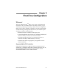
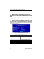
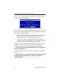
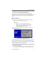
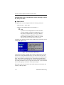
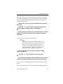
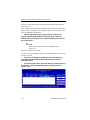
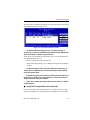
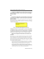
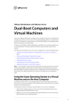
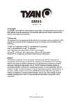
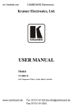
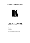
RAID EzAssist™ Configuration Utility Quick Configuration Guide DB15-000277-00 First Edition 08P5520 Proprietary Rights Notice This document contains proprietary information of LSI Logic Corporation. The information contained herein is not to be used by or disclosed to third parties without the express written permission of an officer of LSI Logic Corporation. Any product(s) described herein is/are a licensed product of LSI Logic Corporation. Document Description Document DB15-000277-00 First Edition. November 2002 This document describes the LSI Logic Corporation’s Mylex RAID EzAssist™ Configuration Utility product for Software Kit 5.20 and will remain the official reference source for all revisions/releases of this product until rescinded by an update. Disclaimer It is the policy of LSI Logic to improve products as new technology, components, software, and firmware become available. LSI Logic Corporation reserves the right to make changes to any products herein at any time without notice. All features, functions, and operations described herein may not be marketed by LSI Logic in all parts of the world. In some instances, photographs and figures are of equipment prototypes. Therefore, before using this document, consult your LSI Logic representative for information that is applicable and current. LSI LOGIC DOES NOT ASSUME ANY RESPONSIBILITY OR LIABILITY FOR THE USE OF ANY PRODUCT(S) DESCRIBED HEREIN EXCEPT AS EXPRESSLY AGREED TO IN WRITING BY LSI LOGIC. License Restriction The purchase or use of an LSI Logic product does not convey a license under any patent, copyright, trademark, or other intellectual property right of LSI Logic or third parties. Copyright Notice Copyright © 2001, 2002. LSI Logic Corporation. All rights reserved. Trademark Acknowledgments LSI Logic, the LSI Logic logo, MORE, Mylex, and SANmapping are trademarks or registered trademarks of LSI Logic Corporation. All other brand and product names may be trademarks of their respective companies. LSI Logic Corporation North American Headquarters Milpitas, CA 408-433-8000 JB About This Manual This quick configuration guide covers only RAID EzAssist Configuration Utility startup, first time drive configuration, controller configuration, and “flash” upgrades. For advanced drive and physical device configuration topics as well as all other RAID EzAssist topics, please refer to the RAID EzAssist Configuration Utility User Reference Guide provided on the Mylex Solutions Software Kit 5.20 CD-ROM. Conventions Throughout the manual, the following conventions are used: ❑ This Graphic and Text Identifies a Task. ■ This Graphic and Text Identifies a Subtask Under the Above ☞This graphic and text states a particular action to perform, OR ☞An alternative action to perform. ☛ Note Supplementary information that can have an effect on system performance. Caution Notification that a proscribed action has the potential to adversely affect equipment operation, system performance, or data integrity. WARNING Notification that a proscribed action will definitely result in equipment damage, data loss, or personal injury. Contents Chapter 1 First-Time Configuration Welcome! .......................................................................................... 1-1 Supported Mylex PCI Controllers ............................................... 1-1 How Do I Configure a Mylex Controller for the First Time? ............... 1-2 Power On Your System. ............................................................. 1-2 Start RAID EzAssist. .................................................................. 1-2 Get Started. ................................................................................ 1-2 Choose a Configuration Method. ............................................... 1-5 Option 1: Do an Automatic Configuration. .................................. 1-7 Option 2: Do an Assisted Configuration. .................................. 1-11 Fault Tolerance? ...................................................................... 1-11 Spare Drive? ............................................................................ 1-12 Optimization Priority ................................................................. 1-13 Logical Drive Count .................................................................. 1-14 Capacity Usage ........................................................................ 1-15 Apply the Configuration to the Controller. ................................ 1-16 Option 3: Do a Custom Configuration. ..................................... 1-19 Build Disk Arrays. ..................................................................... 1-20 Define Logical Drives. .............................................................. 1-23 Apply the Configuration to the Controller. ................................ 1-27 Chapter 2 Controller Configuration How Do I View Controller Configuration Information? ....................... 2-3 Enter the Controller Configuration Screen. ................................ 2-3 How Do I Change Global Properties for a Controller? ....................... 2-4 Enter the Properties Menu. ........................................................ 2-4 Enter the Global Properties Screen. .......................................... 2-4 View/Modify Automatic Rebuild Management. ........................... 2-5 View/Modify Rebuild Rate. ......................................................... 2-6 View/Modify Background Inititialization. ..................................... 2-6 View/Modify Background Init Rate. ............................................ 2-7 View/Modify the Check Consistency Rate Setting. .................... 2-7 View/Modify the MORE Rate Setting. ........................................ 2-8 View/Modify the Drive Size Coercion Setting. ............................ 2-8 View/Modify the UserSelected CacheLineSize Setting. ............. 2-9 View the Active CacheLineSize Setting. .................................... 2-9 Accept or Cancel Your Global Property Changes. ..................... 2-9 Manual No. DB15-000277-00 iii How Do I Change Startup Properties for a Controller? .................... 2-11 Enter the Properties Menu. ...................................................... 2-11 Enter the Startup Properties Screen. ....................................... 2-11 View the Disk Spin Up Setting. ................................................. 2-12 View/Modify the Number of Disk Drives per Spin Setting. ........ 2-12 View the Initial Delay Setting. ................................................... 2-12 View/Modify the Delay Between Spins Setting. ........................ 2-13 Accept or Cancel Your Startup Property Changes. .................. 2-13 How Do I Change Advanced Properties? ........................................ 2-14 Enter the Properties Menu. ...................................................... 2-14 Enter the Advanced Properties Screen. ................................... 2-14 View/Modify the Patrol Read Setting. ....................................... 2-15 View/Modify the Patrol Read Delay (Hours) Setting. ................ 2-16 View/Modify the Temporary Offline Setting. ............................. 2-16 View/Modify the Device Health Monitoring (S.M.A.R.T.) Setting. .............................................................. 2-16 View/Modify the S.M.A.R.T. Polling Interval (Minutes) Setting. ................................................................................... 2-17 Accept or Cancel Your Advanced Property Changes. .............. 2-17 Chapter 3 Flash Upgrades How Do I Update Controller Firmware or the RAID EzAssist Utility? 3-1 Update a Controller whose Firmware is Lower than Software Kit 3.04. ..................................................................... 3-2 Enter the Advanced Options Menu. ........................................... 3-2 Choose an Image File for the Update. ....................................... 3-3 Choose Controllers to Update. ................................................... 3-4 Update the Selected Controller(s). ............................................. 3-5 SOFTWARE LICENSE AND WARRANTY POLICY iv RAID EzAssist Quick Config. Chapter 1 First-Time Configuration Welcome! Welcome to RAID EzAssistTM, Mylex’s user friendly configuration and maintenance utility for RAID controllers. This chapter will help you get started step by step doing your first Mylex RAID Controller configuration. Before you are ready to configure a controller, be sure that you have already done the following according to the instructions in your controller’s quick installation or hardware installation guide: • Installed your Mylex controller(s) in the target system • Connected appropriate cables between your controller(s) and the set of disk drives which you intend to use with each controller • Set unique SCSI IDs for each drive on a particular SCSI bus (i.e. attached to each Mylex RAID controller), if necessary • Terminated each SCSI bus appropriately (not applicable for Fibre channel controllers) Supported Mylex PCI Controllers RAID EzAssist supports up to eight (8) controllers. RAID EzAssist for Software Kit 5.x and higher supports the AcceleRAID 160/170LP, 170, 352, and eXtremeRAID 2000 PCI to Ultra 160 SCSI controllers, and the eXtremeRAID 3000 PCI to Fibre Channel controller. Manual No. DB15-000277-00 1-1 How Do I Configure a Mylex Controller for the First Time? How Do I Configure a Mylex Controller for the First Time? ❑ Power On Your System. Regardless of whether an operating system is installed on your computer system, you can run RAID EzAssist from the Mylex controller’s BIOS at system boot time. ☞ Turn on the system’s power switch. ❑ Start RAID EzAssist. As the system boots up, you’ll see various messages on the display. Pay special attention when you see a message similar to the following: <Mylex controller ID1> BIOS Version x.xx-xx (Month Day, Year) Mylex Shortly after, some additional messages from the Mylex controller are displayed, including: Press <Alt-M> for BIOS Options Next you’ll see: Press <Alt-R> for RAID Configuration options ☞ When you see the prompt, press <Alt-R>. If you’ve pressed <Alt-R> within the allotted time, you’ll see: RAID Configuration will start after system initialization completes No system drives installed If you were too late pressing <Alt-R>, simply reboot and start again. ☞ Wait for RAID EzAssist to start. ❑ Get Started. 1. Examples include AcceleRAID 352, eXtremeRAID 2000, etc. 1-2 RAID EzAssist Quick Config. First-Time Configuration ☞ From the Welcome screen (Figure 1-1), select the controller and press Enter. Figure 1-1. Welcome! RAID EzAssist will then scan the Mylex controller and target drives (Figure 1-2). Figure 1-2. RAID EzAssist Scans for Controllers and Drives ☞ Allow scanning to complete. If you have drives of differing capacities, you’ll see a Notice that says, “There are drives of different capacities detected.” If you are using drives of different capacities, there is a possibility that some of the capacity on the larger drives will not be used. With an Automatic Configuration, larger disk drives are initialized down to the capacity of the smallest connected disk drive. Therefore, to be able to use the capacity of your drives to their fullest extent, perform a Custom Configuration when you have drives of differing capacities. With a Custom Configuration, you can create multiple arrays and logical drives to maximize disk drive capacity usage by grouping drives of similar size into separate RAID arrays. See Table 1-1 in the section “Choose a Configuration Method” for more information. Manual No. DB15-000277-00 1-3 How Do I Configure a Mylex Controller for the First Time? ☞ Press Enter to continue. Since this is a first-time configuration, you’ll see a Notice (Figure 1-3). Figure 1-3. No Existing RAID Configuration “Would you like to configure a RAID drive now?” The answer depends on whether you want to change any of the default parameters and settings for this Mylex RAID Controller. If you are a new or inexperienced user, the default settings will probably suit your needs just fine, so you’ll answer Yes. If you are an advanced user, now’s the time to change any controller parameters that you wish, before a RAID configuration is set on the controller, so you’ll answer No. ☞ If you want to adjust controller parameters, use the arrow key to select No, then press Enter. Please see Chapter 2 for information on changing Global, Startup, or Advanced parameters. Return here when you’re done to continue first-time RAID configuration. ☛ Note After changing controller parameters, select Configure a RAID Drive from the main menu to proceed. ☞ If you want to begin configuring your first RAID drive without changing controller options, select Yes, then press Enter. 1-4 RAID EzAssist Quick Config. First-Time Configuration ❑ Choose a Configuration Method. Three configuration methods are available to you. The table below will help you decide which method is most appropriate for your situation. Table 1-1. Selecting a Configuration Method Configuration Method Automatic Who Should Use It -Automatically creates ONE array out of all available disk drives on the controller. -Users who wish to set up a If disk drives are different capacities, single array with one logical larger disk drives are initialized down to drive when all available disk the capacity of the smallest connected disk drive. drives are of similar size/ -RAID level is automatically set based on capacity. -Don’t use this if you want to the number of connected disk drives: -Novice users with little or no RAID experience. span arrays, use RAID 0 striping, or RAID 0+1 mirroring with striping. Assisted Custom What It Does -Users with some knowledge of RAID who wish a step by step configuration approach. -Users who want to set up more than one array or logical drive without the detailed control of Custom configuration. -Experienced or advanced users who want more complete control over configuration options. -Users with disk drives of multiple capacities who wish to create multiple arrays and logical drives to maximize capacity usage. 1 drive = a JBOD 2 drives = a RAID 1 mirrored set 3 drives = a 3-drive RAID 5 striping with parity configuration 4–8 drives = a 3-,4-,5-,6-, or 7-drive RAID 5 striping with parity configuration adding one device as a hot spare. -Leads you step by step through a series of questions about what type of RAID configuration you’re looking for. -Provides detailed control of RAID configuration, including individual selection of physical devices, multiple arrays, multiple logical drives, caching, stripe size, etc. -Allows spanning (RAID 0+1, 10, 30, 50, etc.). To take advantage of performance improvements available with the new user-selected 64K cache line size, make sure stripe size for all logical drives is set to at least 64K, then go to Controller Parameters (Global) to set your cache line size to 64K. (See Chapter 2.) Manual No. DB15-000277-00 1-5 How Do I Configure a Mylex Controller for the First Time? You choose your configuration method from the Configure RAID Drive screen (Figure 1-4). Figure 1-4. Choose a Configuration Method ☞ If you want to do an Automatic configuration, use the arrow key to select Automatic, then press Enter. Now see “Option 1: Do an Automatic Configuration” for details. ☞ If you want to do an Assisted configuration, use the arrow key to select Assisted, then press Enter. Now see “Option 2: Do an Assisted Configuration” for details. ☞ If you want to do a Custom configuration, use the arrow key to select Custom, then press Enter. Now see “Option 3: Do a Custom Configuration” for details. 1-6 RAID EzAssist Quick Config. First-Time Configuration ❑ Option 1: Do an Automatic Configuration. The RAID Configuration Summary screen is displayed showing the recommended configuration for your system (Figure 1-5). Figure 1-5. RAID Configuration Summary Screen Table 1-2. RAID Configuration Summary Fields Field Description Fault Tolerance For 1 disk drive = No For 2 or more disk drives = Yes Spare For 1-3 disk drives = No For 4-8 disk drives = Yes (Dedicated Spare) Optimization For 1 disk drive = Performance (no fault tol) For 2 disk drives = Performance For 3 or more disk drives = Capacity Logical Drive Count 1 Total (usable) Capacity Depends on the fault tolerance overhead: For 1 disk drive of n GB = n GB For 2 disk drives of n GB = n GB For 3 disk drives of n GB = 2n GB For 4,5,6,7,8 disk drives of n GB = 2n,3n,4n,5n,6n GB respectivelya Disk Drive Identification Depends on the disk drives. a. With four or more drives, one drive’s capacity is used for fault tolerance overhead, and one additional drive is reserved as a spare. Manual No. DB15-000277-00 1-7 How Do I Configure a Mylex Controller for the First Time? If there are more than five drives in the array, you’ll see a small down-arrow next to the disk drive display field. ☞ Optional: If there is a down-arrow next to the disk drive display field, press PgDn to see the additional disk drives in the array. ☞ Optional: Alternate PgUp and PgDn to see the entire list of disk drives in the array. ☞ Optional: If you want to see additional configuration details, use the arrow key to select the Details button, then press Enter. If you choose to view configuration details, the RAID Configuration Details screen is displayed (Figure 1-6). Figure 1-6. RAID Configuration Details Screen Table 1-3. RAID Configuration Details Fields Field Description RAID Level For 1 disk drive = JBOD For 2 disk drives = RAID 1 For 3 or more disk drives = RAID 5 Stripe Block Size For 1 disk drive = n/a For 2 or more disk drives = 64 KB Cache Line Size Default = 8KB; tuned to Stripe Block Size Read Cache Normal (default) Write Cache Write-Thru (default) 1-8 RAID EzAssist Quick Config. First-Time Configuration ☛ Note After viewing configuration details, press Enter to select OK and return to the RAID Configuration Summary screen. ☞ To apply the configuration, use the arrow key, if necessary, to select Apply, then press Enter, OR ☞ To cancel the configuration, use the arrow key to select Cancel, then press Enter. When you apply the new configuration, RAID EzAssist writes configuration information to the Mylex controller. This takes a few moments, so a message is displayed (Figure 1-7). Figure 1-7. Writing RAID Configuration. Please Wait... Configuration information is also stored directly on the disk drives. Known as configuration on disk, or COD, this allows you to restore a configuration to a replacement controller in the event of a failed controller. A COD allows for RAID Group Transportability, where the RAID group can be physically moved from one location to another, or from one controller to another. ☞ Wait for the configuration information to be written to the controller. Manual No. DB15-000277-00 1-9 How Do I Configure a Mylex Controller for the First Time? Next you’ll see a Configuration Status screen (Figure 1-8). Your automatic configuration has been completed. Figure 1-8. Configuration Complete – Reboot or Main Menu Your next step will be to install the appropriate Mylex Disk Array Controller driver for the operating system you’ll be using on the computer in which the Mylex RAID Controller is installed. • If you have not installed your operating system software yet, and the Mylex controller is your system’s primary controller, you will need to install the operating system and the Mylex driver concurrently. • If the operating system is already installed, the Mylex controller is a secondary controller. You will need to boot your operating system and install the Mylex driver from within the operating system. In either case, refer to the appropriate operating system chapter in the PCI Disk Array Controller Drivers Installation Guide and User Manual for instructions on primary and secondary controller driver installation. ☞ On a 32-bit system, to exit RAID EzAssist: select the Reboot button and press Enter. A screen appears that says, “System can now be powered off, select OK to reboot.” ☞ At this final screen, press Enter to select OK. Begin operating system installation if necessary, or reboot your installed operating system. 1-10 RAID EzAssist Quick Config. First-Time Configuration ❑ Option 2: Do an Assisted Configuration. The sequence of screens displayed during an Assisted Configuration depends on several factors, such as the number of unconfigured drives on the controller and your responses at each step of the Assisted Configuration process. ■ Fault Tolerance? The Fault Tolerance screen is displayed under the following condition: Number of Unconfigured Drives on Controller > 1 ☛ Note If you have only one unconfigured drive on this controller, your only configuration option is JBOD, a non fault-tolerant option. You will, therefore, NOT see the Fault Tolerance choice screen. Assuming your situation meets the above condition, the Fault Tolerance screen is displayed (Figure 1-9). Figure 1-9. Do You Want Fault Tolerance? In most situations you will want fault tolerance to protect your array in the event of a drive failure. However, if raw performance utilizing maximum available drive capacity overshadows your need for fault tolerance, a RAID 0 (striping) configuration may be more appropriate. ☞ If you want your array to be fault tolerant, use the arrow key to select Yes, then press Enter. ☞ If you prefer a RAID 0 striping or a JBOD configuration and Manual No. DB15-000277-00 1-11 How Do I Configure a Mylex Controller for the First Time? fault tolerance is not a consideration, use the arrow key to select No, then press Enter. ■ Spare Drive? The Spare Drive screen is displayed under the following conditions: • Fault Tolerance = YES, AND • Number of Unconfigured Drives on Controller > 3 ☛ Note If you have two unconfigured drives on this controller, you’ll get a RAID 1 (mirroring) configuration. If you have three unconfigured drives, you’ll get a RAID 5 (striping with parity) configuration. In both cases no drive would be available to act as a spare, so you will therefore NOT see the Spare Drive choice screen. Assuming your situation meets the above conditions, the Spare Drive screen is displayed (Figure 1-10). Figure 1-10. Do You Want a Spare Drive? A spare drive (hot spare or standby drive) offers an additional level of fault tolerance for existing fault tolerant arrays. If a drive in the array fails, the presence of a spare drive allows the failed drive’s data to be rebuilt onto the spare. After rebuild is complete, the array could still accept another drive failure with no loss of data (although there would be degraded performance). It is usually beneficial to reserve a spare drive for the array, if you can afford not to use the capacity of the drive for array data storage. Reserving a spare drive lowers the total usable capacity of the array by the capacity of that spare drive. 1-12 RAID EzAssist Quick Config. First-Time Configuration ☞ If you want your array to reserve a spare drive, use the arrow key to select Yes, then press Enter. ☞ If you prefer not to reserve a spare drive, and thereby use all the available drives in the array, use the arrow key to select No, then press Enter. ■ Optimization Priority The Optimization Priority screen is displayed under the following conditions: • Fault Tolerance = YES, AND • Number of Available1 Drives on Controller > 2 ☛ Note If you have only two available drives on this controller, you’ll get a RAID 1 (mirroring) configuration, which optimizes for performance. You will, therefore, NOT see the Optimization Priority choice screen. Assuming your situation meets the conditions above, the Optimization Priority screen is displayed (Figure 1-11). Figure 1-11. Optimize for Capacity? At this point you choose whether available capacity or array performance is the top criterion in your fault tolerant array. If you choose Capacity, you’ll be requesting a RAID 5 (striping with parity) configuration. If you choose 1. “Available” drives are both unconfigured AND not reserved as a spare. Manual No. DB15-000277-00 1-13 How Do I Configure a Mylex Controller for the First Time? Performance, you’ll be requesting a RAID 0+1 (striping with mirroring) configuration. Both give you the safety of fault tolerance. RAID 5 provides the best combination of settings for most applications and has an overhead of only one drive’s capacity. RAID 0+1 has a write performance advantage over RAID 5, but since the striped set is mirrored, available capacity is only half of the total capacity in the drive set. ☞ If you want to optimize your array for capacity, use the arrow key to select Capacity, then press Enter. ☞ If you want to optimize your array for performance, use the arrow key to select Performance, then press Enter (Figure 1-12). Figure 1-12. Optimize for Performance? ■ Logical Drive Count The Logical Drive Count screen is always displayed in Assisted Configuration. You may divide the available drive space into multiple logical drives, or retain the default of one (1) logical drive. The Logical Drive Count screen is displayed (Figure 1-13). Figure 1-13. Logical Drive Count Each logical drive that you create under Assisted Configuration will have 1-14 RAID EzAssist Quick Config. First-Time Configuration identical capacity and settings (RAID level, caching, etc.). If you wish to set logical drive capacities or settings individually, you must use Custom Configuration. See “Option 3: Do a Custom Configuration.” ☞ If you want to set only one (1) logical drive, select Ok, then press Enter. ☞ If you want to set up multiple logical drives: ☞ Press the up arrow key to select the logical drive count field. ☞ Type in a number of logical drives to set up. ☞ Press the down arrow key to select Ok. ☞ Press Enter with Ok selected. ■ Capacity Usage The Capacity Usage screen is always displayed in Assisted Configuration. You may use all or a part of the total available capacity to set up the specified number of logical drives with the optimization you’ve selected previously. The Capacity Usage screen is displayed (Figure 1-14). Figure 1-14. Capacity Usage By default, the maximum available capacity is displayed in the Capacity Usage field. If you wish to reserve some of the capacity of your drives to set up future arrays, you may choose a smaller gigabyte (GB) value for the current logical drive set. ☞ If you want to use the maximum available capacity for these logical drives, select Ok, then press Enter. Manual No. DB15-000277-00 1-15 How Do I Configure a Mylex Controller for the First Time? ☞ If you want to reserve some capacity for future use: ☞ Press the up arrow key to select the capacity usage field. ☞ Type in a number representing the gigabytes (GB) to be used in the current configuration. (This number must be lower than the maximum value displayed.) ☞ Press the down arrow key to select Ok. ☞ Press Enter. ■ Apply the Configuration to the Controller. The RAID Configuration Summary screen is displayed (Figure 1-15). Figure 1-15. RAID Configuration Summary Screen If there are more than five drives in the array, you’ll see a small down-arrow next to the disk drive display field. ☞ Optional: If there is a down-arrow next to the disk drive display field, press PgDn to see the additional disk drives in the array. ☞ Optional: Alternate PgUp and PgDn to see the entire list of disk drives in the array. 1-16 RAID EzAssist Quick Config. First-Time Configuration ☞ Optional: If you want to see additional configuration details, use the arrow key to select the Details button, then press Enter. If you choose to view configuration details, the RAID Configuration Details screen is displayed (Figure 1-16). Figure 1-16. RAID Configuration Details Screen ☛ Note After viewing configuration details, press Enter to select OK and return to the RAID Configuration Summary screen. ☞ To apply the configuration, use the arrow key if necessary to select Apply, then press Enter, OR ☞ To cancel the configuration, use the arrow key to select Cancel, then press Enter. When you apply the new configuration, RAID EzAssist writes configuration information to the Mylex controller and drives. This takes a few moments, so a message is displayed (Figure 1-17). Figure 1-17. Writing RAID Configuration. Please Wait... Configuration information is also stored directly on the disk drives. Known Manual No. DB15-000277-00 1-17 How Do I Configure a Mylex Controller for the First Time? as configuration on disk, or COD, this allows you to restore a configuration to a replacement controller in the event of a failed controller. A COD allows for RAID Group Transportability, where the RAID group can be physically moved from one location to another, or from one controller to another. ☞ Wait for the configuration information to be written to the controller. Next you’ll see a Configuration Status screen (Figure 1-18). Your assisted configuration has been completed. Figure 1-18. Configuration Complete – Reboot or Main Menu ☛ Note To take advantage of performance improvements available when all logical drives have a 64K stripe size, go to Controller Parameters (Global) to set your cache line size to 64K. (See Chapter 2.) Your next step will be to install the appropriate Mylex Disk Array Controller driver for the operating system you’ll be using on the computer in which the Mylex RAID Controller is installed. • If you have not installed your operating system software yet, and the Mylex controller is your system’s primary controller, you will need to install the operating system and the Mylex driver concurrently. • If the operating system is already installed, the Mylex controller is a secondary controller. You will need to boot your operating system and install the Mylex driver from within the operating system. In either case, refer to the appropriate operating system chapter in the PCI Disk Array Controller Drivers Installation Guide and User Manual for instructions on primary and secondary controller driver installation. ☞ On a 32-bit system, to exit RAID EzAssist: select the Reboot 1-18 RAID EzAssist Quick Config. First-Time Configuration button and press Enter. A screen appears that says, “System can now be powered off, select OK to reboot.” ☞ At this final screen, press Enter to select OK. Begin operating system installation if necessary, or reboot your installed operating system. ❑ Option 3: Do a Custom Configuration. Custom Configuration gives you full control over the configuration of your disk drives. With Custom Configuration, you can: • Select individual disk drives to add to the configuration • Build multiple arrays • Configure logical drives individually • Select a specific RAID level • Select the write caching method (Write-Thru or Write-Back) • Set the stripe size per logical drive • Set logical drive size by physical or logical capacity • Add capacity to an existing array • Assign additional spare drives • Enable spanning to create a configuration of larger drive sets Once you’ve selected Custom from the Configure RAID Drive screen, the Custom Configuration main menu is displayed (Figure 1-19). Figure 1-19. Custom Configuration Main Menu We are setting up a first-time configuration, so we’ll use the menu’s first option: Configure a New Disk Array. ☞ Select the Configure a New Disk Array option and press Enter. Manual No. DB15-000277-00 1-19 How Do I Configure a Mylex Controller for the First Time? ■ Build Disk Arrays. The first step in Custom Configuration is to build at least one disk array. This is accomplished from the Disk Array Configuration screen (Figure 1-20). Figure 1-20. Disk Array Configuration Screen If you have two (2) or more controllers sharing the same channel, the ChanNo/Status box on the Disk Array Configuration screen will indicate the channel as “Shared” (Figure 1-21). Figure 1-21. ChanNo/Status Box with “Shared” Channel This screen uses the following navigation strategy: • PgDn and PgUp show you all the available drives if there is a small down-arrow beside the Unused Drives field. • Inside Unused Drives, arrow keys select a drive, Enter accepts the highlighted drive and adds it to the Disk Array box to the right. • The Tab key shifts control to the buttons, or from the buttons back to Unused Drives. • When buttons are in focus, arrow keys select a button and Enter activates the highlighted button. 1-20 RAID EzAssist Quick Config. First-Time Configuration Caution The drives you select to comprise the array will all be treated as having the capacity of the smallest selected drive, regardless of the actual capacities. This could lead to wasted drive space. Therefore, try whenever possible to select drives of similar capacity when building an array. “How many drives should I select for an array?” The answer depends on the RAID levels you want to be able to choose for the logical drives you’ll set up in that array. See Table 1-4. Table 1-4. Required Numbers of Drives By RAID Level Desired RAID Level Number of Drives to Select JBOD (Single Drive) Exactly 1 drive RAID 0 (Striping) At least 2 drives of equal size RAID 1 (Mirroring) Exactly 2 drives of equal size RAID 3 (Parity Drive) At least 3 drives of equal size RAID 5 (Striping with Parity) RAID 0+1 (Striping with Mirroring) ☞ Use the arrow keys to select a disk drive in the Unused Drives field, then press Enter to accept the drive into the disk array. ☞ Repeat the step above for as many disk drives as you wish to add to the array. ☞ When you’ve finished adding drives, press the Tab key to switch focus to the buttons. Figure 1-22 is an example of how your screen might look after the steps above. Manual No. DB15-000277-00 1-21 How Do I Configure a Mylex Controller for the First Time? Figure 1-22. Sample Disk Array Configuration ☞ If you’re not satisfied with your drive selections, use the arrow key to select Clear, then Press Enter. Press Tab to return to Unused Drives. Your selections will be erased and you can try again as described above. ☞ To save the array you’ve set up, select Save Array and press Enter. A Notice is displayed at this point as shown in Figure 1-23. Figure 1-23. Define Logical Drives or Return to Disk Array Set-Up “Do you want to build additional arrays at this time?” If you want to set up additional arrays, it is convenient to do so at this time before logical drives are defined. 1-22 RAID EzAssist Quick Config. First-Time Configuration ☛ Note If you want to take advantage of “spanning” your configuration across multiple arrays, you must enable spanning FIRST, build the individual arrays, then create logical drives that can make use of the spanned capacity available. See Chapter 2 of the RAID EzAssist Configuration Utility User Reference Guide for more complete information about this option. If you plan on only one array, or if you’d prefer to define logical drives before building any additional arrays, you should move on to define logical drives at this time. ☞ To build additional disk arrays, use the arrow key, if necessary, to select No, then press Enter. Repeat the steps described in “Build Disk Arrays.” ☞ To define logical drives at this time, use the arrow key, if necessary, to select Yes, then press Enter. ■ Define Logical Drives. Logical drives for the array(s) you just set up are defined from the Logical Drive Definition screen (Figure 1-24). Logical drives can be created in any order. Figure 1-24. Logical Drive Definition Screen This screen uses the following navigation strategy: • Arrow keys move among the logical drive definition fields. Manual No. DB15-000277-00 1-23 How Do I Configure a Mylex Controller for the First Time? • For RAID Level, Write Cache, and Stripe Size (KB) definition fields, the Spacebar brings up a list of valid options. Arrow keys move among the options and Enter selects an option. • For RAID Level, Write Cache, and Stripe Size (KB) definition fields, the + and - keys cycle through the valid options. When the desired option is visible, use the arrow key to move to another field. • For Physical Capacity or Logical Capacity definition fields, type a numeric decimal value representing the desired capacity in GB. You may choose one or the other field to adjust. • The Tab key shifts control to the buttons, or from the buttons back to the logical drive definition fields. • When buttons are in focus, arrow keys select a button and Enter activates the highlighted button. Arrow keys rotate selections through Add Drive, Apply, Cancel, Clear New, and Delete Last. Let’s start by selecting a RAID level for our first logical drive. ☞ With the RAID Level definition field selected... ☞ Press the + or - key to find your desired RAID level, OR ☞ Press Spacebar to display a box of available choices, use the arrow key to select your desired RAID level, then press Enter (Figure 1-25). Figure 1-25. Example of a Selection Box Next, we’ll select the write caching strategy for our logical drive. 1-24 RAID EzAssist Quick Config. First-Time Configuration Write Back caching speeds write performance but risks loss of data in the cache buffer should power fail. Use Write Back only if you have a battery backup unit (BBU) or uninterruptable power supply (UPS) installed to preserve data in the cache. ☞ Use the right arrow key to select the Write Cache definition field, then... ☞ Press the + or - key to find your desired caching method (“Thru” for Write Through, “Back” for Write Back), OR ☞ Press Spacebar to display a box of available choices, use the arrow key to select your desired write caching method, then press Enter. Next, we’ll set the stripe size for this logical drive. ☛ Note Depending on the controller, available stripe sizes are 8, 16, 32, 64, 128, 256, 512, and 1024. If you set the stripe size of all logical drives on the controller to at least 64K, you can make use of 64K cache line size to improve performance. Change the cache line size in Controller Parameters (Global). See Chapter 2. ☞ Use the right arrow key to select the Stripe Size (KB) definition field, then... ☞ Press the + or - key to find your desired stripe size, OR ☞ Press Spacebar to display a box of available choices, use the arrow key to select your desired stripe size, then press Enter. Next, we set a size for this logical drive based on the maximum available capacity. You can set logical drive size in terms of either physical capacity or logical Manual No. DB15-000277-00 1-25 How Do I Configure a Mylex Controller for the First Time? capacity. Logical capacity takes into account overhead for fault tolerance, spare drives, etc. If you intend to set up more than one logical drive in this array, then set the capacity for the first logical drive somewhere below the maximum to leave space for additional logical drives. ☞ Use the right arrow key to select either the Physical or Logical Capacity (GB) definition field, then type a numeric decimal value for the physical or logical capacity to be used in this logical drive. ☛ Note Drive capacity may be rounded for alignment with block sizes. Finally, let’s add the logical drive. Check your settings among the logical drive definition fields to be sure they are what you want. ☞ If you wish to change any settings, use the arrow key to select the desired definition field and change its value as described earlier. ☞ To add the logical drive, press the tab key to switch focus to the buttons, select the Add Drive button, then press Enter (Figure 1-26). Figure 1-26. Ready to Add the Logical Drive 1-26 RAID EzAssist Quick Config. First-Time Configuration The logical drive is added to the display box, and focus returns to the logical drive definition field line (Figure 1-27). Figure 1-27. Logical Drive Has Been Added ☞ To define additional logical drives, use the arrow key, if necessary, to return to the RAID Level definition field. Repeat the steps described in “Define Logical Drives.” At this point, you can delete the logical drives you’ve set up and define new ones. RAID EzAssist lets you: • Delete a logical drive you’ve added, OR • Delete all the logical drives you’ve added in this logical drive definition session. ☞ To delete a logical drive, press the tab key, if necessary, to switch focus to the buttons, use the arrow key to select Delete Last, then press Enter. ☞ To delete all logical drives that you added, press the tab key, if necessary, to switch focus to the buttons, use the arrow key to select Clear New, then press Enter. ☞ If you wish, define new logical drives as described in “Define Logical Drives.” ■ Apply the Configuration to the Controller. In order for the disk arrays and logical drives you set up to become a valid, registered configuration, you must Apply the configuration to the controller. Manual No. DB15-000277-00 1-27 How Do I Configure a Mylex Controller for the First Time? ☞ To apply the configuration, press the tab key, if necessary, to switch focus to the buttons, use the arrow key to select Apply, then press Enter, OR ☞ To cancel the configuration, press the tab key, if necessary, to switch focus to the buttons, use the arrow key to select Cancel, then press Enter. When you apply the new configuration, RAID EzAssist writes configuration information to the Mylex controller. This takes a few moments, so a message is displayed (Figure 1-28). Figure 1-28. Writing RAID Configuration. Please Wait... Configuration information is also stored directly on the disk drives. Known as configuration on disk, or COD, this allows you to restore a configuration to a replacement controller in the event of a failed controller. A COD allows for RAID Group Transportability, where the RAID group can be physically moved from one location to another, or from one controller to another. ☞ Wait for the configuration information to be written to the controller. When the process is complete, RAID EzAssist brings you back to the Disk Array Configuration screen, or Welcome menu if all drives are assigned. Your next step will be to install the appropriate Mylex Disk Array Controller driver for the operating system you’ll be using on the computer in which the Mylex RAID Controller is installed. • If you have not installed your operating system software yet, and the Mylex controller is your system’s primary controller, you will need to install the operating system and the Mylex driver concurrently. • If the operating system is already installed, the Mylex controller is a secondary controller. You will need to boot your operating system and install the Mylex driver from within the operating system. 1-28 RAID EzAssist Quick Config. First-Time Configuration In either case, refer to the appropriate operating system chapter in the PCI Disk Array Controller Drivers Installation Guide and User Manual for instructions on primary and secondary controller driver installation. ☞ Press the Esc key multiple times until you see the screen in Figure 1-29 below. Figure 1-29. Do You Wish to Exit RAID EzAssist? ☞ On a 32-bit system, to exit RAID EzAssist: use the arrow key to select Yes, then press Enter. A screen appears that says, “System can now be powered off, select OK to reboot.” ☞ At this final screen, press Enter to select OK. Begin operating system installation if necessary, or reboot your installed operating system. Manual No. DB15-000277-00 1-29 How Do I Configure a Mylex Controller for the First Time? 1-30 RAID EzAssist Quick Config. Chapter 2 Controller Configuration You can change certain settings on your controller using RAID EzAssist. Each Mylex Disk Array Controller is shipped from the factory with default settings which have been found to work well in a majority of applications and environments. However, no two environments are the same, and you may want to modify certain settings. The best time to make such changes is prior to doing your first drive configuration on the controller. This chapter will discuss the following: • Changing Global Properties • Changing Startup Properties • Changing Advanced Properties The following table is a summary of the specific properties you are able to change along with their default values. Manual No. DB15-000277-00 2-1 Table 2-1. Summary of Controller Parameters Property Type Global Startup Advanced 2-2 Parameter Default Setting Automatic Rebuild Management Disabled Rebuild Rate 50 Background Initialization Enabled Background Init Rate 50 Check Consistency Rate 50 MORE Rate 50 Drive Size Coercion Disabled UserSelected CacheLineSize 8 (KB) Active CacheLineSize 8 (KB) Disk Spin Up On Command Number of Disk Drives per Spin 2 Initial Delay (seconds) 5 Delay Between Spins (seconds) 0 Patrol Read Disabled Patrol Read Delay (hours) 0 Temporary Offline Disabled Device Health Monitoring (S.M.A.R.T.) Disabled S.M.A.R.T. Polling Interval (minutes) 0 RAID EzAssist Quick Config. Controller Configuration How Do I View Controller Configuration Information? ❑ Enter the Controller Configuration Screen. ☞ If necessary, select the controller you wish to configure from the “Welcome to RAID EzAssist” screen. The RAID EzAssist main menu includes several options (Figure 2-1), Figure 2-1. View or Modify Controller Configuration ☞ Use the arrow key to select View or Modify Controller Configuration on the main menu, then press Enter. The Controller Configuration screen is displayed showing basic controller configuration information (Figure 2-2). Figure 2-2. Controller Configuration Screen Manual No. DB15-000277-00 2-3 How Do I Change Global Properties for a Controller? How Do I Change Global Properties for a Controller? ❑ Enter the Properties Menu. To view and possibly change Global properties of the controller, you enter the Properties menu from the Controller Configuration screen. ☞ Press Enter with Properties selected on the Controller Configuration screen. The Properties menu is displayed (Figure 2-3). Figure 2-3. Properties Menu Overlays Controller Configuration Screen ❑ Enter the Global Properties Screen. ☞ When the Properties menu is displayed, select Global, then press Enter. 2-4 RAID EzAssist Quick Config. Controller Configuration The Global Properties screen is displayed (Figure 2-4). Figure 2-4. Global Properties Screen This screen uses the following navigation strategy: • Arrow keys move among the property fields. • The Spacebar brings up a list of valid options. Arrow keys move among the options and Enter selects an option. • The + and - keys cycle through the valid options. When the desired option is visible, use the arrow key to move to another field. • The Tab key shifts control to the buttons, or from the buttons back to the property fields. • When buttons are in focus, arrow keys select a button and Enter activates the highlighted button. • At any time you can press Enter to accept the current settings and close the screen. ❑ View/Modify Automatic Rebuild Management. Default = Disabled The Automatic Rebuild Management option refers to the function of the same name. It detects the removal of a failed drive and performs an automatic rebuild after a replacement drive is installed into a redundant (fault tolerant) logical array (RAID 1, 3, 5, and 0+1). Automatic Rebuild Management requires hardware compatibility with disk array enclosures that are certified AEMI or SAF-TE compliant. Manual No. DB15-000277-00 2-5 How Do I Change Global Properties for a Controller? ☞ With the Automatic Rebuild Management field selected... ☞ Press the + or - key to set the value to Enabled or Disabled as desired, OR ☞ Press Spacebar to display a box of available choices, use the arrow key to select your desired setting, then press Enter. ❑ View/Modify Rebuild Rate. Default = 50 The Rebuild Rate is a relative indication of how much time the controller devotes to a rebuild. A rate of 50 assigns the maximum allowable resources to a drive rebuild or array expansion, allowing the Rebuld or Expand to proceed at its fastest. Lowering the number devotes more resources to I/Os and consequently slows the Rebuild or Expand Array process. This parameter takes effect immediately without resetting the controller(s). ☞ Use the arrow key to select the Rebuild Rate field, then... ☞ Press the + or - key to select the desired numeric value for rebuild processes, OR ☞ Press Spacebar to display a box of available choices, use the arrow key to select your desired value, then press Enter. ❑ View/Modify Background Inititialization. Default = Enabled The Background Initialization option allows a logical device or system drive to be initialized as a background operation while reads and writes are being performed. ☞ With the Background Initialization field selected... ☞ Press the + or - key to set the value to Enabled or Disabled as 2-6 RAID EzAssist Quick Config. Controller Configuration desired, OR ☞ Press Spacebar to display a box of available choices, use the arrow key to select your desired setting, then press Enter. ❑ View/Modify Background Init Rate. Default = 50 The Background Initialization Rate is a relative indication of how much time the controller devotes to a background initialization operation. Integer values from 0-50 can be defined in multiples of 10. For low priority and high array performance, specify a value of 0. For a high background initialization rate (with reduced array performance), select 50. ☞ Use the arrow key to select the Background Init Rate field, then... ☞ Press the + or - key to select the desired numeric value for background initialization processes, OR ☞ Press Spacebar to display a box of available choices, use the arrow key to select your desired value, then press Enter. ❑ View/Modify the Check Consistency Rate Setting. Default = 50 The Check Consistency Rate is a relative indication of how much time the controller devotes to a Consistency Check. For lower priority and higher array performance, specify a lower value. For higher Consistency Check priority (with reduced array performance), specify a higher value. A Consistency Check is a process that verifies the integrity of redundant data, and gives the user the ability to have a discrepancy reported and corrected. ☞ Use the arrow key to select the Check Consistency Rate field, Manual No. DB15-000277-00 2-7 How Do I Change Global Properties for a Controller? then... ☞ Press the + or - key to set the desired value, OR ☞ Press Spacebar to display a box of available choices, use the arrow key to select your desired value, then press Enter. ❑ View/Modify the MORE Rate Setting. Default = 50 The MORE Rate is a relative indication of how much time the contoller devotes to Online RAID Expansion. For lower priority and higher array performance, specify a lower value. For higher MORE priority (with reduced array performance), specify a higher value. ☞ Use the arrow key to select the MORE Rate field, then... ☞ Press the + or - key to set the desired value, OR ☞ Press Spacebar to display a box of available choices, use the arrow key to select your desired value, then press Enter. ❑ View/Modify the Drive Size Coercion Setting. Default = Disabled Enable this setting to allow drives of similar but not exact capacities to be treated as identical in capacity for the purpose of hot spares, drive replacements, and array configurations. ☞ Use the arrow key to select the Drive Size Coercion field, then... ☞ Press the + or - key to set the value to Enabled or Disabled as desired, OR ☞ Press Spacebar to display a box of available choices, use the 2-8 RAID EzAssist Quick Config. Controller Configuration arrow key to select your desired value, then press Enter. ❑ View/Modify the UserSelected CacheLineSize Setting. Default = 8KB The Cache Line Size can be set to 64KB by the user to enhance performance if the Stripe Size setting of ALL logical drives configured on the controller is 64KB or larger. The Active CacheLineSize field below this field indicates what Cache Line Size the controller is currently using. Even if you select 64KB Cache Line Size, the Active field will remain at 8KB if any logical drives have a Stripe Size smaller than 64KB. ☞ Use the arrow key to select the UserSelected CacheLineSize field, then... ☞ Press the + or - key to set the value to 64KB or 8KB as desired, OR ☞ Press Spacebar to display a box of available choices, use the arrow key to select your desired value, then press Enter. ❑ View the Active CacheLineSize Setting. Read Only Field = 8KB or 64KB The Active CacheLineSize field indicates what Cache Line Size the controller is currently using. This value will read 8KB unless (1) all logical drive Stripe Sizes are 64KB or larger, AND (2) the user has changed the UserSelected CacheLineSize field to 64KB and saved the change. Even if you select 64KB Cache Line Size, the Active field will remain at 8KB if any logical drives have a Stripe Size smaller than 64KB. ❑ Accept or Cancel Your Global Property Changes. ☞ To accept your Global property changes, press Enter with Ok selected. Manual No. DB15-000277-00 2-9 How Do I Change Global Properties for a Controller? If you changed the UserSelected CacheLineSize field from 8KB to 64KB, the following screen is displayed (Figure 2-5). Figure 2-5. Notice About Stripe Size Requirement ☞ If you see the Notice, press Enter to continue. ☞ Press the arrow key to select Yes at the “Save Changes?” screen and press Enter, OR ☞ To cancel any changes you’ve made, press the Esc key, or press the Tab key, the arrow key to select Cancel, then press Enter. 2-10 RAID EzAssist Quick Config. Controller Configuration How Do I Change Startup Properties for a Controller? ❑ Enter the Properties Menu. To view and possibly change Startup properties of the controller, you enter the Properties menu from the Controller Configuration screen. ☞ Press Enter with Properties selected on the Controller Configuration screen. The Properties menu is displayed (Figure 2-6). Figure 2-6. Properties Menu Overlays Controller Configuration Screen ❑ Enter the Startup Properties Screen. ☞ When the Properties menu is displayed, use the arrow key to select Startup, then press Enter. The Startup Properties screen is displayed (Figure 2-7). Figure 2-7. Startup Properties Screen Manual No. DB15-000277-00 2-11 How Do I Change Startup Properties for a Controller? This screen uses the following navigation strategy: • Arrow keys move among the property fields. • The Disk Spin Up field is fixed at “On Command.” • The Initial Delay (seconds) field is fixed at “5.” • For the Number of Disk Drives per Spin and Delay Between Spins (seconds) fields, type a numeric value representing the desired setting. • The Tab key shifts control to the buttons, or from the buttons back to the property fields. • When buttons are in focus, arrow keys select a button and Enter activates the highlighted button. • At any time you can press Enter to accept the currently visible settings and close the screen. ❑ View the Disk Spin Up Setting. Fixed = On Command The Disk Spin Up setting controls how the SCSI drives in the array are started (spun-up). On Command. This mode will spin-up drives on command from the user. This is the only value for disk spin-up. ❑ View/Modify the Number of Disk Drives per Spin Setting. Default = 2 The Number of Disk Drives per Spin setting specifies the number of drives to spin up at one time. Values range from 1 to 6. ☞ Use the arrow keys to select the Number of Disk Drives per Spin field, then type the desired numeric value for the number of disk drives per spin. ❑ View the Initial Delay Setting. Fixed = 5 After the controller completes its initialization process, the initial delay value defines the number of seconds before the first disk interrogation 2-12 RAID EzAssist Quick Config. Controller Configuration request is issued to the array. This value is set to 5 seconds and cannot be changed. ❑ View/Modify the Delay Between Spins Setting. Default = 0 The Delay Between Spins setting specifies the number of seconds between consecutive device spin-up cycles. ☞ Use the arrow keys to select the Delay Between Spins (seconds) field, then type the desired numeric value for the number of seconds of delay between spins. ❑ Accept or Cancel Your Startup Property Changes. ☞ To accept your Startup property changes, select Ok, then press Enter, then press the arrow key to select Yes at the “Save Changes?” screen and press Enter, OR ☞ To cancel any changes you’ve made, press the Esc key, or press the tab key, the arrow key to select Cancel, then press Enter. Manual No. DB15-000277-00 2-13 How Do I Change Advanced Properties? How Do I Change Advanced Properties? ❑ Enter the Properties Menu. To view and possibly change Advanced properties of the controller, you enter the Properties menu from the Controller Configuration screen. ☞ Press Enter with Properties selected on the Controller Configuration screen. The Properties menu is displayed (Figure 2-8). Figure 2-8. Properties Menu Overlays Controller Configuration Screen ❑ Enter the Advanced Properties Screen. ☞ When the Properties menu is displayed, use the arrow key to select Advanced, then press Enter. The Advanced Properties screen is displayed (Figure 2-9). Figure 2-9. Advanced Properties Screen This screen uses the following navigation strategies: • Arrow keys move among the property fields. 2-14 RAID EzAssist Quick Config. Controller Configuration • The Spacebar brings up a list of options. Arrow keys move among the options and Enter selects and option. • The + and - keys cycle through the valid options. When the desired option is visible, use the arrow key to move to another field. • The Tab key shifts control to the buttons, or from the buttons back to the property fields. • When Buttons are in focus, arrow keys select a button and Enter activates the highlighted button. • At any time you can press Enter to accept the currently visible settings and close the screen. ☛ Note Patrol Read Delay (hours) is only available when Patrol Read is Enabled. S.M.A.R.T. Polling Interval (minutes) is only available when Device Health Monitoring (S.M.A.R.T.) is Enabled. ❑ View/Modify the Patrol Read Setting. Default = Disabled As opposed to a consistency check, which reads all sectors and validates either the parity or mirror pair of the drive, a Patrol Read periodically verifies all sectors, including the COD, on the configured drives. With periodic checking, any potential problems could be found before the host accesses data. If Enabled, Patrol Read will initialize when a controller has been idle for a defined period of time and no other background tasks are active. ☞ Use the arrow key to select the Patrol Read field, then... ☞ Press the + or - key to set the value to Enabled or Disabled as desired, OR ☞ Press Spacebar to display a box of available choices, use the Manual No. DB15-000277-00 2-15 How Do I Change Advanced Properties? arrow key to select your desired value, then press Enter. ❑ View/Modify the Patrol Read Delay (Hours) Setting. Default = 0 This specifies the number of hours between one Patrol Read and the next. Values range from 1 to 1016 hours. ☞ Use the arrow keys to select the Patrol Read Delay (hours) field, then use the + or - keys to set the desired numeric value for the number of hours between Patrol Reads. ❑ View/Modify the Temporary Offline Setting. Default = Disabled The Temporary Offline feature prevents a physical drive associated with a currently critical system drive, or a physical drive associated with an online non-redundant system drive, from being permanently marked offline. The Temporary Offline feature increases reliability of recovering data by decreasing the chances of marking a RAID array permanently Offline, which will result in data loss. ☞ Use the arrow key to select the Temporary Offline field, then... ☞ Press the + or - key to set the value to Enabled or Disabled as desired, OR ☞ Press Spacebar to display a box of available choices, use the arrow key to select your desired value, then press Enter. ❑ View/Modify the Device Health Monitoring (S.M.A.R.T.) Setting. Default = Disabled If Enabled, the Device Health Monitoring (S.M.A.R.T.) feature will scan physical devices for Informational Exception Conditions (IEC) and Predictive Failure Analysis (PFA) warnings and return the warnings to the user. 2-16 RAID EzAssist Quick Config. Controller Configuration S.M.A.R.T. stands for Self-Monitoring Analysis and Reporting Technology. ☞ Use the arrow key to select the Device Health Monitoring (S.M.A.R.T) field, then... ☞ Press the + or - key to set the value to Enabled or Disabled as desired, OR ☞ Press Spacebar to display a box of available choices, use the arrow key to select your desired value, then press Enter. ❑ View/Modify the S.M.A.R.T. Polling Interval (Minutes) Setting. Default = 0 This feature sets the number of minutes between each S.M.A.R.T. poll. Values range from 0 to 255. A value of 255 means no delay between polls. ☞ Use the arrow keys to select the S.M.A.R.T Polling Interval (minutes) field, then use the + or - keys to set the desired numeric value for the number of minutes between S.M.A.R.T polls. ❑ Accept or Cancel Your Advanced Property Changes. ☞ To accept your Advanced property changes, select Ok, then press Enter, then press the arrow key to select Yes at the “Save Changes?” screen and press Enter, OR ☞ To cancel any changes you’ve made, press the Esc key, or press the tab key, or the arrow key to select Cancel, then press Enter. Manual No. DB15-000277-00 2-17 How Do I Change Advanced Properties? 2-18 RAID EzAssist Quick Config. Chapter 3 Flash Upgrades In this chapter you’ll learn how to use RAID EzAssist to update (flash) new firmware code to one or more Mylex RAID Controllers, or update the RAID EzAssist BIOS Configuration Utility itself. How Do I Update Controller Firmware or the RAID EzAssist Utility? From time to time LSI Logic makes available updated firmware or BIOS code with new features or fixes for your controller. RAID EzAssist offers a straightforward way to update (“flash”) the new code to your controller. In addition, you can even use RAID EzAssist to update itself! The same Update Flash Code function can be used to update the BIOS version of RAID EzAssist on your controller. ☛ Note Whether you’re updating firmware, BIOS code, RAID EzAssist, etc., you will need to reboot your system for the new code to take effect. Be sure you know what Software Kit firmware version your controller has before you continue. WARNING Only update your controller firmware if the current firmware is from Software Kit 3.04 or higher. Updating controllers that have firmware lower than Software Kit 3.04 will render the controller unusable. If your firmware is Software Kit 3.04 or higher, continue with the section “Enter the Advanced Options Menu.” If your firmware is lower than Software Kit 3.04, continue with the section “Update a Controller whose Firmware is Lower than Software Kit 3.04.” Manual No. DB15-000277-00 3-1 How Do I Update Controller Firmware or the RAID EzAssist Utility? ❑ Update a Controller whose Firmware is Lower than Software Kit 3.04. ☞ First update RAID EzAssist. Follow the instructions in the section “Enter the Advanced Options Menu,” but select the RAID EzAssist image file. Updating RAID EzAssist first will guard against accidently flashing the wrong files. Reboot and press <Alt-R> when prompted to run EzAssist. ☞ Update the controller firmware to Software Kit 3.04 firmware. Follow the instructions in the section “Enter the Advanced Options Menu.” After you have updated your controller firmware to Software Kit 3.04 firmware, you can safely flash the firmware version contained in this Software Kit. ❑ Enter the Advanced Options Menu. ☞ Use the arrow key to select Advanced Options on the main menu, then press Enter (Figure 3-1). Figure 3-1. Advanced Options The Advanced Options menu is displayed (Figure 3-2). Figure 3-2. Advanced Options Menu 3-2 RAID EzAssist Quick Config. Flash Upgrades ❑ Choose an Image File for the Update. ☞ Have the diskette ready that contains the firmware, BIOS, boot block, or utility image file(s) you want to flash from the root directory, and record the name(s) of the file(s) you’ll be flashing. ☞ From the Advanced Options menu, select Update Flash Code, then press Enter. The Update Flash Code screen is displayed (Figure 3-3). For example: Figure 3-3. Update Flash Code ☞Type the pathname of the image file, then press the tab key. ☞Insert the diskette into the floppy diskette drive, select Ok, then press Enter to continue. A message is displayed while RAID EzAssist reads the image file (Figure 3-4). Figure 3-4. Reading Image File ☞Wait while the image file data is being read. Manual No. DB15-000277-00 3-3 How Do I Update Controller Firmware or the RAID EzAssist Utility? The Flash Code Update screen is displayed (Figure 3-5). Figure 3-5. Flash Code Update ❑ Choose Controllers to Update. The image file is read from the diskette, then the contents of the image file are displayed in the gray field at the top of the screen. This screen uses the following navigation strategy: • PgDn and PgUp show you all the available or selected controllers if there is a small down/up-arrow beside the Controller field. • Inside the Controller field, arrow keys select a controller. Enter accepts the highlighted controller and adds a check mark, OR deselects a controller that already has a check mark. You may select more than one controller. • The Tab key shifts control to the buttons, or from the buttons back to the Controller field. • When buttons are in focus, arrow keys select a button and Enter activates the highlighted button. ☞ Use the arrow keys to select a controller you wish to update, then press Enter. Repeat to select additional controllers. The currently active controller is selected by default. 3-4 RAID EzAssist Quick Config. Flash Upgrades ❑ Update the Selected Controller(s). ☞ After you’ve selected all controllers to update, press the tab key to select Ok, then press Enter. If the following Error message is displayed (Figure 3-6), return to the section “Update a Controller whose Firmware is Lower than 3.04” on page 3-2, and follow the instructions to update your controller. Figure 3-6. Error in Store Image Message The Flash Code Update warning is displayed (Figure 3-7). Figure 3-7. Flash Code Update Warning ☞To begin the update (flash) process, use the arrow key to select Yes, then press Enter, OR ☞To cancel the update, select No, then press Enter. If you selected Yes, the Flash Process Status screen is displayed (Figure 3-8). Manual No. DB15-000277-00 3-5 How Do I Update Controller Firmware or the RAID EzAssist Utility? Figure 3-8. Flash Process Status RAID EzAssist loads the image file information to the controller and stores it. ☞ Wait for the flash image storage to conclude. Once the image file has been stored to the controller, RAID EzAssist will automatically program the controller with the new image data. A message is displayed (Figure 3-9). Figure 3-9. Programming Controller ☞ Wait while the controller is programmed. When the process is finished, the Flash Process Status screen will indicate “Flashing done” for each successfully updated controller. 3-6 RAID EzAssist Quick Config. LSI LOGIC CORPORATION SOFTWARE LICENSE AND WARRANTY POLICY Limited Warranty LSI warrants to the original purchaser of the product enclosed herein (“Customer”) that (a) for a period of three (3) years from the date of Customer’s purchase of the Product (excluding batteries and memory) (the “Product Warranty Period”), and (b) for a period of one (1) year from the date of purchase of the Product by Customer (the “Battery/Memory Warranty Period”), the batteries and memory included in the Product will (i) be free from defects in workmanship and materials, and (ii) substantially conform to the documentation or other specifications for the Product. The limited warranties herein shall not apply to and shall be void for any Product that has been misused (including static discharge, improper installation, or accident), abused, modified, damaged as a result of actions on the part of Customer or its agents or its processes, unauthorized service or parts, used in a manner inconsistent with normal computer operations (including but not limited to electrical irregularities, lightning or power line related damage, or other abnormal occurrences), or to normal wear and tear of the Product. The warranty herein is made to and for the benefit of the original purchaser of this Product and is non-transferable. This warranty will not apply to, and LSI provides no warranty for any BIOS, software, ROM-based firmware or other product developed or manufactured by any third party whether including with this Product or not. Such warranty or warranties are provided by third parties and, to the extent permitted thereby, shall be made available and are hereby assigned by LSI to Customer. Customer may obtain warranty service during the Product Warranty Period or Battery/Memory Warranty Period, as the case may be, if (a) Customer has contacted LSI at the telephone number listed LSI’s web site at www.lsilogic.com to obtain a Returned Material Authorization (“RMA”) number and appropriate instructions from LSI, (b) after obtaining LSI’s authorization, Customer has returned the Product if so instructed to an authorized LSI service facility or to LSI in accordance with LSI’s instructions and the terms of this Agreement, shipping costs to be borne by LSI, and (c) Customer has provided proof of purchase price and date for unregistered Product. LSI shall bear one-way shipping, packing and insurance costs and all other costs, excluding labor and parts, necessary to effectuate repair or replacement under this warranty. All Product repaired or replaced under this warranty shall be returned to Customer at Customer’s expense. Repair or replacement Product provided under this limited Product warranty will be furnished on an exchange basis and may be new or reconditioned. All Product returned under this warranty shall become the property of LSI. LSI shall notify Customer in the event that the Product returned under the warranty does not, in LSI’s sole determination, comply with the conditions and requirements set forth herein and, unless disposition instructions are given by Customer for the Product within thirty (30) days of such notification, the Product shall be returned to Customer freight collect. Warranty Disclaimer EXCEPT AS SET FORTH IN THIS DOCUMENT, LSI MAKES NO WARRANTIES, WHETHER EXPRESS, IMPLIED, OR STATUTORY REGARDING OR RELATING TO THE PRODUCT, OR ANY MATERIALS OR SERVICES FURNISHED OR PROVIDED TO OEM UNDER THIS AGREEMENT, INCLUDING MAINTENANCE AND SUPPORT. LSI SPECIFICALLY DISCLAIMS ALL IMPLIED WARRANTIES, INCLUDING, WITHOUT LIMITATION, THE IMPLIED WARRANTIES OF NON-INFRINGEMENT, MERCHANTABILITY AND FITNESS FOR A PARTICULAR PURPOSE WITH RESPECT TO THE PRODUCT AND ANY OTHER MATERIALS AND SERVICES, AND WITH RESPECT TO THE USE OF ANY OF THE FOREGOING. THE REMEDIES STATED IN THIS DOCUMENT CONSTITUTE CUSTOMER’S EXCLUSIVE REMEDIES AND LSI’S SOLE LIABILITY FOR BREACH OF THE LIMITED WARRANTIES SET FORTH HEREIN. Software License Subject to the terms and conditions of this Agreement, LSI grants Customer a non-exclusive, worldwide, non-transferable, revocable, royalty-free license to use, perform and display the LSI software that is a part of the Product (“LSI Software”) solely as part of the Product incorporated into the OEM Products that and not on a standalone basis. Customer may not (a) sell, lease, license, or sublicense the LSI Software, (b) de-compile, disassemble, reverse engineer, or otherwise attempt to derive source code from the LSI Software, in whole or in part, except to the extent such restriction is prohibited by applicable law, (c) modify or create derivative works from the LSI Software, or (d) use the LSI Software to provide processing services to third parties or otherwise use the LSI Software on a service bureau basis, electronically distribute or timeshare the LSI Software or market the LSI Software by interactive cable or remote processing services. Limitation of Liability IN NO EVENT SHALL LSI’S TOTAL, CUMULATIVE LIABILITY ARISING FROM THE SALE, USE AND DISPOSITION OF THE PRODUCT AND/OR THE LICENSING OF THE LSI SOFTWARE EXCEED THE AMOUNT PAID BY CUSTOMER FOR THIS PRODUCT. IN NO EVENT SHALL LSI BE LIABLE TO CUSTOMER OR ANY THE OTHER FOR ANY PUNITIVE, INCIDENTAL, INDIRECT, CONSEQUENTIAL OR SPECIAL DAMAGES, INCLUDING LOSS OF PROFITS, INCURRED BY THAT PARTY, HOWEVER CAUSED AND UNDER ANY THEORY OF LIABILITY, WHETHER BASED IN CONTRACT, TORT (INCLUDING, WITHOUT LIMITATION, NEGLIGENCE OR PRODUCT LIABILITY) OR WARRANTY, IN CONNECTION WITH THE SALE, USE AND DISPOSITION OF THE PRODUCT AND/OR THE LICENSING OF THE LSI SOFTWARE, EVEN IF ADVISED OF THE POSSIBILITY OF SUCH DAMAGES. Manual No. DB15-000277-00 08P5520 LSI Logic Corporation North American Headquarters Milpitas, CA 408.433.8000