1
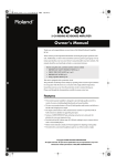
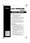
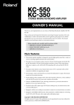
OWNER’S MANUAL
Thank you for purchasing the Roland Bi-Amp Monitor DS-30A.
201b
Before using this unit, carefully read the sections entitled: “IMPORTANT SAFETY
INSTRUCTIONS” (p. 3), “USING THE UNIT SAFELY” (p. 4), and “IMPORTANT NOTES”
(p. 5). These sections provide important information concerning the proper operation
of the unit. Additionally, in order to feel assured that you have gained a good grasp of
every feature provided by your new unit, Owner’s manual should be read in its
entirety. The manual should be saved and kept on hand as a convenient reference.
Main Features
● In Pursuit of High Sound Quality
The DS-30A powered monitor uses a two-way, bi-amplifier
design to achieve high sound quality.
The monitor features a 120-mm LF Driver and a 25-mm
soft-dome HF Driver as speakers. The amplification
includes 20-watt and 10-watt amplifiers designed to
achieve high sound quality.
Amplifier
10W
Amplifier
20W
● Analog Input
In addition to an XLR connector, which provides for
balanced input, a 1/4" TRS phone jack accommodating either balanced or unbalanced input
is also provided. This assures broad-ranging connectivity.
● Digital Input
The DS-30A is provided with digital input connectors (coaxial and optical) that support 96
kHz sample rate and 24-bit digital audio.
Digitally input signals are reproduced faithfully through 24-bit D/A conversion, thus
preventing noise or a drop in sound quality.
You can use the monitors with a wide variety of equipment and applications through
selective use of the analog and digital settings.
● Magnetically Shielded Low- and High-Frequency Drivers
This allows you to use the speakers next to CRT displays.
202
Copyright © 2002 ROLAND CORPORATION
All rights reserved. No part of this publication may be reproduced in any form without the
written permission of ROLAND CORPORATION.
For EU Countries
This product complies with the requirements of European Directives EMC 89/336/EEC and LVD 73/23/EEC.
For the USA
FEDERAL COMMUNICATIONS COMMISSION
RADIO FREQUENCY INTERFERENCE STATEMENT
This equipment has been tested and found to comply with the limits for a Class B digital device, pursuant to Part 15 of the
FCC Rules. These limits are designed to provide reasonable protection against harmful interference in a residential
installation. This equipment generates, uses, and can radiate radio frequency energy and, if not installed and used in
accordance with the instructions, may cause harmful interference to radio communications. However, there is no guarantee
that interference will not occur in a particular installation. If this equipment does cause harmful interference to radio or
television reception, which can be determined by turning the equipment off and on, the user is encouraged to try to correct the
interference by one or more of the following measures:
– Reorient or relocate the receiving antenna.
– Increase the separation between the equipment and receiver.
– Connect the equipment into an outlet on a circuit different from that to which the receiver is connected.
– Consult the dealer or an experienced radio/TV technician for help.
This device complies with Part 15 of the FCC Rules. Operation is subject to the following two conditions:
(1) This device may not cause harmful interference, and
(2) This device must accept any interference received, including interference that may cause undesired operation.
Unauthorized changes or modification to this system can void the users authority to operate this equipment.
This equipment requires shielded interface cables in order to meet FCC class B Limit.
For Canada
NOTICE
This Class B digital apparatus meets all requirements of the Canadian Interference-Causing Equipment Regulations.
AVIS
Cet appareil numérique de la classe B respecte toutes les exigences du Règlement sur le matériel brouilleur du Canada.
2
IMPORTANT SAFETY INSTRUCTIONS
CAUTION
RISK OF ELECTRIC SHOCK
DO NOT OPEN
ATTENTION: RISQUE DE CHOC ELECTRIQUE NE PAS OUVRIR
CAUTION: TO REDUCE THE RISK OF ELECTRIC SHOCK,
DO NOT REMOVE COVER (OR BACK).
NO USER-SERVICEABLE PARTS INSIDE.
REFER SERVICING TO QUALIFIED SERVICE PERSONNEL.
The lightning flash with arrowhead symbol, within an
equilateral triangle, is intended to alert the user to the
presence of uninsulated “dangerous voltage” within the
product’s enclosure that may be of sufficient magnitude to
constitute a risk of electric shock to persons.
The exclamation point within an equilateral triangle is
intended to alert the user to the presence of important
operating and maintenance (servicing) instructions in the
literature accompanying the product.
INSTRUCTIONS PERTAINING TO A RISK OF FIRE, ELECTRIC SHOCK, OR INJURY TO PERSONS.
IMPORTANT SAFETY INSTRUCTIONS
SAVE THESE INSTRUCTIONS
WARNING - When using electric products, basic precautions should always be followed, including the following:
1.
2.
3.
4.
5.
6.
7.
8.
9.
Read these instructions.
Keep these instructions.
Heed all warnings.
Follow all instructions.
Do not use this apparatus near water.
Clean only with a dry cloth.
Do not block any of the ventilation openings. Install in
accordance with the manufacturers instructions.
Do not install near any heat sources such as radiators,
heat registers, stoves, or other apparatus (including
amplifiers) that produce heat.
Do not defeat the safety purpose of the polarized or
grounding-type plug. A polarized plug has two blades with
one wider than the other. A grounding type plug has two
blades and a third grounding prong. The wide blade or the
third prong are provided for your safety. When the provided
plug does not fit into your outlet, consult an electrician for
replacement of the obsolete outlet.
10. Protect the power cord from being walked on or pinched
particularly at plugs, convenience receptacles, and the
point where they exit from the apparatus.
11. Only use attachments/accessories specified by the
manufacturer.
12. Never use with a cart, stand, tripod, bracket,
or table except as specified by the
manufacturer, or sold with the apparatus.
When a cart is used, use caution when
moving the cart/apparatus combination to
avoid injury from tip-over.
13. Unplug this apparatus during lightning storms or when
unused for long periods of time.
14. Refer all servicing to qualified service personnel. Servicing
is required when the apparatus has been damaged in any
way, such as power-supply cord or plug is damaged, liquid
has been spilled or objects have fallen into the apparatus,
the apparatus has been exposed to rain or moisture, does
not operate normally, or has been dropped.
For the U.K.
WARNING:
THIS APPARATUS MUST BE EARTHED
IMPORTANT: THE WIRES IN THIS MAINS LEAD ARE COLOURED IN ACCORDANCE WITH THE FOLLOWING CODE.
GREEN-AND-YELLOW: EARTH, BLUE: NEUTRAL, BROWN: LIVE
As the colours of the wires in the mains lead of this apparatus may not correspond with the coloured markings identifying
the terminals in your plug, proceed as follows:
The wire which is coloured GREEN-AND-YELLOW must be connected to the terminal in the plug which is marked by the
letter E or by the safety earth symbol or coloured GREEN or GREEN-AND-YELLOW.
The wire which is coloured BLUE must be connected to the terminal which is marked with the letter N or coloured BLACK.
The wire which is coloured BROWN must be connected to the terminal which is marked with the letter L or coloured RED.
3
USING THE UNIT SAFELY
Used for instructions intended to alert
the user to the risk of death or severe
injury should the unit be used
improperly.
Used for instructions intended to alert
the user to the risk of injury or material
damage should the unit be used
improperly.
* Material damage refers
other adverse effects
respect to the home
furnishings, as well
animals or pets.
001
•
Before using this unit, make sure to
read the instructions below, and the
Owner’s Manual.
010
•
......................................................................
002a
•
Do not open or perform any internal
modifications on the unit.
......................................................................
003
•
Do not attempt to repair the unit, or
replace parts within it (except when
this manual provides specific instructions directing you to do so). Refer all
servicing to your retailer, the nearest
Roland Service Center, or an authorized Roland distributor, as listed on
the “Information” page.
•
Never use or store the unit in places
that are:
• Subject to temperature extremes
(e.g., direct sunlight in an enclosed
vehicle, near a heating duct, on top
of heat-generating equipment); or
are
• Damp (e.g., baths, washrooms, on
wet floors); or are
• Humid; or are
• Exposed to rain; or are
• Dusty; or are
• Subject to high levels of vibration.
......................................................................
007
•
Make sure you always have the unit
placed so it is level and sure to remain
stable. Never place it on stands that
could wobble, or on inclined surfaces.
•
013
•
......................................................................
009
•
Do not excessively twist or bend the
power cord, nor place heavy objects
on it. Doing so can damage the cord,
producing severed elements and short
circuits. Damaged cords are fire and
shock hazards!
......................................................................
Do not allow any objects (e.g.,
flammable material, coins, pins); or
liquids of any kind (water, soft drinks,
etc.) to penetrate the unit.
In households with small children, an
adult should provide supervision until
the child is capable of following all the
rules essential for the safe operation of
the unit.
014
•
Protect the unit from strong impact.
(Do not drop it!)
.....................................................................
015
•
Do not force the unit’s power-supply
cord to share an outlet with an unreasonable number of other devices. Be
especially careful when using
extension cords—the total power used
by all devices you have connected to
the extension cord’s outlet must never
exceed the power rating (watts/
amperes) for the extension cord.
Excessive loads can cause the
insulation on the cord to heat up and
eventually melt through.
.....................................................................
016
•
Before using the unit in a foreign
country, consult with your retailer, the
nearest Roland Service Center, or an
authorized Roland distributor, as
listed on the "Information" page.
.....................................................................
026
•
Do not put anything that contains
water (e.g., flower vases) on this unit.
Also, avoid the use of insecticides,
perfumes, alcohol, nail polish, spray
cans, etc., near the unit. Swiftly wipe
away any liquid that spills on the unit
using a dry, soft cloth.
.....................................................................
4
101a
•
The unit should be located so that its
location or position does not interfere
with its proper ventilation.
......................................................................
102b
•
Always grasp only the plug on the
power-supply cord when plugging
into, or unplugging from, an outlet or
this unit.
......................................................................
104
•
Try to prevent cords and cables from
becoming entangled. Also, all cords
and cables should be placed so they
are out of the reach of children.
......................................................................
106
•
107b
•
Never climb on top of, nor place heavy
objects on the unit.
Never handle the power cord or its
plugs with wet hands when plugging
into, or unplugging from, an outlet or
this unit.
......................................................................
108a
•
.....................................................................
The unit should be connected to a
power supply only of the type
described in the operating instructions, or as marked on the unit.
Use only the attached power-supply
cord.
This unit, either alone or in combination with an amplifier and
headphones or speakers, may be
capable of producing sound levels that
could cause permanent hearing loss.
Do not operate for a long period of
time at a high volume level, or at a
level that is uncomfortable. If you
experience any hearing loss or ringing
in the ears, you should immediately
stop using the unit, and consult an
audiologist.
......................................................................
......................................................................
008e
The ● symbol alerts the user to things that must be
carried out. The specific thing that must be done is
indicated by the design contained within the circle. In
the case of the symbol at left, it means that the powercord plug must be unplugged from the outlet.
.....................................................................
......................................................................
008a
•
The
symbol alerts the user to items that must never
be carried out (are forbidden). The specific thing that
must not be done is indicated by the design contained
within the circle. In the case of the symbol at left, it
means that the unit must never be disassembled.
.....................................................................
011
•
......................................................................
004
to damage or
caused with
and all its
to domestic
The
symbol alerts the user to important instructions
or warnings.The specific meaning of the symbol is
determined by the design contained within the
triangle. In the case of the symbol at left, it is used for
general cautions, warnings, or alerts to danger.
Before moving the unit, disconnect the
power plug from the outlet, and pull
out all cords from external devices.
......................................................................
109a
•
Before cleaning the unit, turn off the
power and unplug the power cord
from the outlet (p. 5).
......................................................................
110a
•
Whenever you suspect the possibility
of lightning in your area, pull the plug
on the power cord out of the outlet.
......................................................................
118
•
Should you remove the optical
connector caps, make sure to put them
in a safe place out of children's reach,
so there is no chance of them being
swallowed accidentally.
......................................................................
119
•
The top of the unit may become hot, so
take care to avoid burns.
......................................................................
IMPORTANT NOTES
291b
In addition to the items listed under “IMPORTANT SAFETY INSTRUCTIONS” and “USING THE UNIT SAFELY” on page 3
and 4, please read and observe the following:
Power Supply
301
•
307
•
Do not use this unit on the same power circuit with any device that
will generate line noise (such as an electric motor or variable lighting
system).
add 1
•
add 2
•
Before connecting this unit to other devices, turn off the power to all
units. This will help prevent malfunctions and/or damage to
speakers or other devices.
*
Placement
351
•
352a
•
352b
•
354b
•
355
•
356
•
357
•
359
•
Using the unit near power amplifiers (or other equipment containing
large power transformers) may induce hum. To alleviate the
problem, change the orientation of this unit; or move it farther away
from the source of interference.
This device may interfere with radio and television reception. Do not
use this device in the vicinity of such receivers.
Noise may be produced if wireless communications devices, such as
cell phones, are operated in the vicinity of this unit. Such noise could
occur when receiving or initiating a call, or while conversing. Should
you experience such problems, you should relocate such wireless
devices so they are at a greater distance from this unit, or switch
them off.
Do not expose the unit to direct sunlight, place it near devices that
radiate heat, leave it inside an enclosed vehicle, or otherwise subject
it to temperature extremes. Also, do not allow lighting devices that
normally are used while their light source is very close to the unit
(such as a piano light), or powerful spotlights to shine upon the same
area of the unit for extended periods of time. Excessive heat can
deform or discolor the unit.
To avoid possible breakdown, do not use the unit in a wet area, such
as an area exposed to rain or other moisture.
Do not allow rubber, vinyl, or similar materials to remain on the unit
for long periods of time. Such objects can discolor or otherwise
harmfully affect the finish.
Do not put anything that contains water (e.g., flower vases) on the
unit. Also, avoid the use of insecticides, perfumes, alcohol, nail
polish, spray cans, etc., near the unit. Swiftly wipe away any liquid
that spills on the unit using a dry, soft cloth.
Do not paste stickers, decals, or the like to this instrument. Peeling
such matter off the instrument may damage the exterior finish.
During operation, this unit must be placed at a distance of no less
than 20 cm from any walls.
Do not allow objects to remain on top of the unit while it is in
operation.
• If you cover the top of the unit, the function is defeated, and
temperature can rise to overly high level, which could cause burns
if they are accidentally touched.
Please also refer to Important Notes on Placement (p. 9).
Maintenance
401a
•
402
•
For everyday cleaning wipe the unit with a soft, dry cloth or one that
has been slightly dampened with water. To remove stubborn dirt,
use a cloth impregnated with a mild, non-abrasive detergent. Afterwards, be sure to wipe the unit thoroughly with a soft, dry cloth.
Never use benzine, thinners, alcohol or solvents of any kind, to avoid
the possibility of discoloration and/or deformation.
Additional Precautions
553
•
556
•
557
•
558b
•
559a
•
562
•
Use a reasonable amount of care when using the unit’s buttons,
sliders, or other controls; and when using its jacks and connectors.
Rough handling can lead to malfunctions.
When connecting / disconnecting all cables, grasp the connector
itself—never pull on the cable. This way you will avoid causing
shorts, or damage to the cable’s internal elements.
A small amount of heat will radiate from the unit during normal
operation.
To avoid disturbing your neighbors, try to keep the unit’s volume at
reasonable levels (especially when it is late at night).
When you need to transport the unit, package it in the box (including
padding) that it came in, if possible. Otherwise, you will need to use
equivalent packaging materials.
Use a cable from Roland to make the connection. If using some other
make of connection cable, please note the following precautions.
• Some connection cables contain resistors. Do not use cables that
incorporate resistors for connecting to this unit. The use of such
cables can cause the sound level to be extremely low, or impossible to hear. For information on cable specifications, contact the
manufacturer of the cable.
Table of Contents
Main Features........................................................................................................................................ 1
USING THE UNIT SAFELY.................................................................................................................... 4
IMPORTANT NOTES ............................................................................................................................. 5
Table of Contents.................................................................................................................................. 5
Panel Descriptions................................................................................................................................ 6
Front ............................................................................................................................................................. 6
Rear............................................................................................................................................................... 6
Connection Examples .......................................................................................................................... 8
Using Two DS-30A Monitors for Stereo Sound ..................................................................................... 8
Important Notes on Placement................................................................................................................. 9
Precautions When Connecting and Turning on the Power ................................................................. 9
Reference............................................................................................................................................. 10
Troubleshooting........................................................................................................................................ 10
Specifications............................................................................................................................................. 10
Dimensions................................................................................................................................................ 11
Frequency Response................................................................................................................................. 11
5
Panel Descriptions
Front
fig.
Power Indicator
HF Driver
Lights when power is on.
* Do not touch the diaphragm.
Digital In Indicator
LF Driver
* Do not touch the speaker cone.
This lights up when output is received from a
connected digital device or during standby.
Connect the digital-signal output device, set the
"Input Select switch" to DIGITAL INPUT, and set
the "Digital Input select switch" according to the
connector to which the device is attached (Coaxial
or Optical).
Bass-reflex Ducts
* When the connected digital-signal output device
is not powered up, the Digital In indicator does not
light up.
Power Switch
These are conduits
for rich, bass-range reproduction.
This switch turns the power on/off.
Before turning the power on or off, you
must lower the volume of this unit and
your connected device etc.
This unit is equipped with a protection
circuit. A brief interval (a few seconds)
after power up is required before the unit
will operate normally.
Rear
1 Digital Input
fig.
Coaxial Input Connector (Digital Input)
This is the digital input connector for coaxial cable.
It cannot be used for input of analog audio signals (no sound
is produced).
5
6
4
3
7
Optical Input Connector (Digital Input)
This is the digital input connector for optic-fiber cable. Use
commercially available optical cable for audio equipment to
make the connection.
2
8
Optical-connector Protective Cap
Power cord
1
6
• After removing the protective cap, put in a safe place so
that it doesn’t get lost.
• When not using the optical connector, attach the cap to
keep the connector safe.
• When using the optical connector, be sure that the cap
you removed is placed out of the reach of children. If a
child has accidentally swallowed a cap, see a doctor
immediately.
Panel Descriptions
Digital Input Select Switch
5 Level Control
This switch selects Optical or Coaxial. Select the connector
used for the input signal.
This adjusts the input level. Turning the control clockwise
increases the sound from the speakers.
Assign Switch
This switch selects the stereo position of the digital signal.
6 HF Trim Control
It selects Right, L+R, or Left when using two DS-30A
monitors for stereo sound (with digital signals).
This adjusts the sound quality of the treble range
(10 kHz, +/-3 dB).
Choose the setting appropriate for your setup.
7 LF Trim Control
With the DS-30A, there is no difference between L and R.
When using the digital input connectors of two DS-30A monitors
for stereo sound, the digital signal can be input to either L or R.
2 Thru (Digital Out) Connector
When connecting multiple DS-30A monitors with digital
signals, this connector is used for output to the second DS-30A.
This adjusts the sound quality of the bass range
(80 Hz, +/-3 dB).
The LF Trim and HF Trim controls on the DS-30A are
designed to correct the sound quality of the sonic field. Use
these to make fine adjustments to match the usage conditions.
8 AC Inlet
Refer to Connection Examples (p. 8).
Connect the included Power cord here. Plug it firmly in, so
that the cable does not accidentally become disconnected.
3 Analog Input
XLR/TRS Phone Input Connector (Analog Input)
This is for connecting XLR or TRS phone plugs.
fig.
XLR type
TRS
Phone type phone type
(Unbalanced) (Balanced)
Both balanced and unbalanced connections are possible.
922b
This instrument is equipped with balanced (XLR/TRS) type
input jacks. Wiring diagrams for these jacks are shown
below. Make connections after first checking the wiring
diagrams of other equipment you intend to connect.
fig.
GND(SLEEVE)
1:GND
2:HOT
3:COLD
HOT(TIP)
COLD(RING)
4 Input Select Switch
Used to select Digital Input or Analog Input.
Select the connector used for the input signal.
7
Connection Examples
Using Two DS-30A Monitors for Stereo Sound
fig.
Example for
Using Analog Input Connectors
Example for
Using Digital Input Connectors
DIGITAL IN
(COAXIAL)
Select
THRU
(DIGITAL OUT)
Recording Equipment,etc.
DIGITAL IN
(COAXIAL)
(OPTICAL)
DIGITAL OUT
Mixer,etc.
CD Player, MD Player,etc.
BR-8/532/1180, etc
Tips about high sound quality playback
• Please pay careful attention to the placement location. In order to take full advantage of the low-frequency
playback capabilities of this device, we recommend that you place it on a hard and strong base.
• When using digital in connections, turn down the LEVEL knob of this device and raise the output level of the
connected device. This will take advantage of the full number of bits in the digital signal, improving the audio
quality.
8
Connection Examples
Important Notes on Placement
• During setup and transport, be careful not to damage the
vibrating portions (the speaker cone and diaphragm).
• When this unit is in operation, the top side will become
hot. Take care not to touch it.
• Be sure to place the monitor so that the slits on the top to
radiate the heat is not obstructed. Also, make sure the
monitor does not touch any curtains or other fabrics.
• Do not put anything on the unit.
• This unit performs cooling when the monitor is placed as
shown below. Do not place the monitor on its side or
upside down.
• During operation, this unit must be placed at a distance
of no less than 20 cm from any walls.
fig.
no less
than 20cm
no less
than 20cm
fig.
Heated Air
no less
than 20cm
no less
than 20cm
* Please also refer to “Placement” in IMPORTANT NOTES (p.
5).
Precautions When Connecting and Turning on the Power
921
942
• To prevent malfunction and/or damage to speakers or
other devices, always turn down the volume, and turn
off the power on all devices before making any
connections.
• This unit is equipped with a protection circuit. A brief
interval (a few seconds) after power up is required
before the unit will operate normally.
941
• Once the connections have been completed, turn on
power to your various devices in the order specified. By
turning on devices in the wrong order, you risk causing
malfunction and/or damage to speakers and other
devices. (When turning the power off, reverse this
procedure.)
1. Turn on the power on the devices connected to the
DS-30A.
2. Turn on the power on the DS-30A.
9
Reference
Troubleshooting
If there is no sound or if the unit does not operate as you expect, please check the following points first. If this does not resolve the
problem, contact the nearest Roland service center or authorized Roland distributor.
There’s No Sound
• Make sure the Input Level control has not been turned
fully counterclockwise.
• Make sure the Input Select switch has been set to the
connector where the input signal is connected (Digital
Input or Analog Input).
• Make sure the Digital Input select switch has been set to
the connector where the input signal is connected
(Optical or Coaxial).
• Input a digital signal to the Digital Input connector. No
sound is produced when an analog signal is input.
926
The volume level of the instrument
connected to ANALOG INPUT is too
low
• Could you be using a connection cable that contains a
resistor? Use a connection cable that does not contain a
resistor.
During Digital Signal Input, the Stereo
Image Is Reversed or Sounds
Unnatural, or Output Doesn’t Sound
Like Stereo
• Check the setting of the Assign switch (Right, L+R, or
Left). The DS-30A uses an identical construction for the
left and right monitors, and makes no distinction
between left and right. During digital signal input, set
the Assign switch L or R as appropriate for your setup.
Specifications
• System
2-Way Bi-Amplified Monitor
• Enclosure
Bass-reflex type
• Cabinet
1/2" PB (Baffle: 5/8" MDF)
• LF Driver
120 mm (5") Foamed polypropylene cone type,
magnetically shielded
• HF Driver
25 mm (1") Soft dome type, magnetically shielded
• Frequency Response
78 Hz to 20 kHz (+/-3 dB)
• Crossover Frequency
2.3 kHz (active third order)
• LF Amplifier Power
20 W
• HF Amplifier Power
10 W
Analog in
• Input Sensitivity
0 dBu (0.775 Vrms)
• Input Impedance
20 k ohms (Balanced/Unbalanced)
10
Digital in
• Format
Conformity with S/P DIF
• Sample Rate
32 kHz to 96 kHz (de-emphasis: OFF)
• D/A Converter
24 bits
• Controls
LEVEL Knob
LF TRIM Knob (80 Hz, +/-3 dB)
HF TRIM Knob (10 kHz, +/-3 dB)
INPUT SELECT SW (Analog In/Digital In)
ASSIGN SW (Right/L+R/Left)
DIGITAL INPUT SELECT SW (Optical/Coaxial)
POWER SW
• Indicators
POWER
DIGITAL IN
• Connectors
ANALOG INPUT (XLR / 1/4 inch TRS phone type)
DIGITAL INPUT (Optical)
DIGITAL INPUT (Coaxial)
DIGITAL THRU OUT (Coaxial)
Reference
• Power Supply
AC 117 V, AC 230 V, AC 240 V
• Weight
6.1 kg/13 lbs 8 oz
• Accessories
Owner's Manual
Power Cord
• Power Consumption
40 W
• Dimensions
176 (W) x 249.5 (D) x 280 (H) mm
6-15/16 (W) x 9-7/8 (D) x 11-1/16 (H) inches
962a
* In the interest of product improvement, the specifications and/or appearance of this unit are subject to change without prior notice.
Dimensions
fig.
176 (6-15/16")
241 (9-1/2")
280
(11-1/16")
8.5
(3/8")
249.5 (9-7/8")
* Not include the power cord.
Frequency Response
fig.
(dB) 20
10
Response
HF: max
flat
LF: max
flat
0
LF: min
-10
HF: min
-20
-30
30
50
100
200
500
1k
2k
5k
10k
20k (Hz)
Frequency
11
02901001
2RCC